

Page 1
Ei144e Ei146e
For full User Instructions
Ei144e Ei146e
for Republic of Ireland Customers
scan the QR code below
+353 (0)61 471277
Ei Electronics. Shannon, V14 H020, Co.Clare, Ireland
www.eielectronics.ie
www.aico.co.uk
Aico Ltd, Oswestry, Shropshire SY10 8NR, UK
P/N B20501 Rev1
+44 (0)1691 664100
scan the QR code below
for UK Customers
For full User Instructions
1
© Ei Electronics 2021
Page 2

Introduction
This Alarm is intended to be used as a device that provides a
loud warning when it detects smoke/heat to alert people of an
immediate danger enabling them to evacuate their dwelling
promptly.
It must be installed in accordance with the latest standards and
is for indoor use only.
This device is mains powered with built-in battery back-up suitable
for use in residential applications. It can be interconnected by
hardwire or RF and must be installed and interconnected by
a qualified electrician.
This Alarm can only be used according to the instructions as
described in the user manual. All use other than that described
in the user manual is seen as unintended use.
Please read the user manual in full before installing or using the
Alarm.
2
Page 3
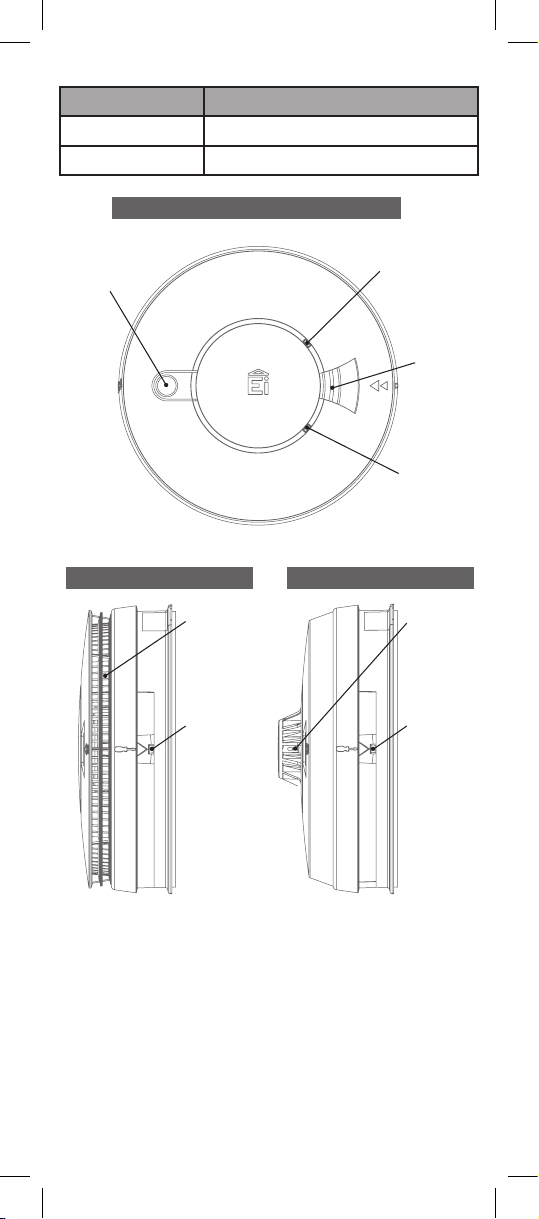
Product Overview
Models Alarm Ty pe
Ei14 6e
Ei14 4 e
Test / Hush
Button
Optical Smoke Alarm
Heat Alarm
Top View
Red LED
Alarm Indicator
Alarm
Sounder
Green LED
Power Indicator
Ei146e Optical Alarm
Smoke Entry
Vents
Alarm
Removal
Latch
3
Ei144e Heat Alarm
Heat Sensor
(Thermistor)
Alarm
Removal
Latch
Page 4

Technical Specification
Power Supply
Power Consumption
Max Current Draw
Battery Backup
Alarm Sounder
Alarm Sound Level
Test/Hush Button
Visual indicators
Operational Life
Interconnection
Fixings
Operating & Storage
Temperature
Humidity Range
230V AC, 50Hz
0.25W (standby)
60mA
9V Replaceable Alkaline battery
Piezoelectric Horn
85dB(A) at 3 meters (min)
Checks sensors, electronics,
interconnection and sounder.
If the unit is in alarm when pressed, it
silences the alarm for 10min
Green LED – Power supply
Red LED – Memory, alarm (if coincides
with horn sounding) or fault
10 years
Units can be interconnected via a
hardwired or wireless system (using
optional Ei168RC RF base)
Supplied with Easi-fit anti-tamper
mounting plate with integral terminal
block and wiring cover, includes screws
and wall plugs
-10°C to +40°C*
15% to 95% RH (non-condensing)
* Temperature and Humidity conditions are for normal operation
and storage. The Alarms will function outside these ranges as
required by the specific product standards. Extended exposure
to conditions outside these ranges can reduce product life. For
advice on prolonged operation outside these range consult the
manufacturer.
Important Safety Instructions
WARNING: Mains operated Alarms must be installed and
interconnected by a qualified electrician in accordance with
the local Regulations for Electrical Installations. Failure to
install this Alarm correctly may expose the user to shock or
fire hazards and damage the product.
The Alarm is designed to be permanently mounted, using its own
built-in terminal block to connect it to the mains. The mounting
plate can be screwed directly to the ceiling. Alternatively, it can
be screwed to a standard junction box (BS 4662 single gang
accessory box). The Alarm must not be exposed to dripping or
splashing. There are important markings on the underside of the
Alarm.
4
Page 5
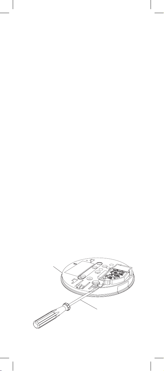
ATTENTION:
Foam ceiling gasket
(must be in place)
Insert screwdriver
to lift and remove
wiring cover
Alternative Energy Sources - (Wind, Solar, UPS etc.)
This product is designed to be connected to a Pure or True Sine
Wave 230V AC supply.
If connecting to a power source that utilises an inverter, e.g. PV
solar panel, the Total Harmonic Distortion (THD) must be less
than 5% . If in doubt please check with the manufacturer of the
inverter.
This also applies to battery powered UPS (Uninterruptible Power
Supply) inverters.
Light Dimmer Circuits – The Alarms must not be powered from
a light dimmer circuit.
IMPORTANT PRECAUTION: Do not install Alarms in new or
renovated buildings until all work is completed.
The Alarm must not be connected when the house wiring
insulation is being checked with high voltages. i.e. Do not use a
high voltage insulation tester on the Alarm.
ATTENTION: The Alarm must be continuously powered 24 hours
a day so it is important that it is not on a circuit that can be
turned off by a switch.
WARNING: Electrical installations must comply with local
regulations.
WARNING: An all-pole mains switch shall be incorporated in the
electrical installation of the building.
WARNING: Always test the Alarm after battery replacement
and only use recommended 9V Alkaline battery. Do not expose
battery to excessive heat such as sunshine, fire, etc...
Mounting and Wiring
Disconnect the AC mains supply from the circuit that is going
to be used.
WARNING: to prevent injury, this apparatus must be securely
attached to the ceiling or wall in accordance with the installation
instructions.
Figure 1
5
Page 6
Place the mounting plate exactly where you want to mount the
Alarm. With a pencil mark the location of the two screw holes . Taking
care to avoid any electrical wiring in the ceiling/wall, drill holes using
a 5.0mm drill bit through the centre of the marked locations. Push
the plastic screw anchors provided into the drilled holes.
Lift off the wiring cover using a flat head screwdriver as shown
in Figure 1.
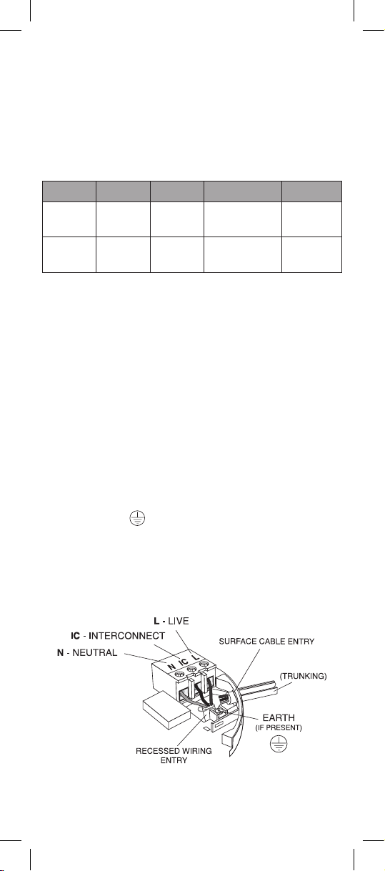
The wiring must be connected to the terminal block on the
mounting plate as follows:
Country Live Neutral Interconnect Earth
Ireland Brown Blue White
UK Brown Blue Black
Green/
Yellow
Green/
Yellow
WARNING: Wiring must be installed in compliance with local
regulations.
WARNING: Mixing the Live and Neutral connections when
interconnecting Alarms may damage all the Alarms - ensure that
the same colours are used throughout the premises for Live,
Neutral and Interconnect wires.
We strongly recommend that you check for the following before
connecting the Alarm:
• check for Live and Neutral using a two probe tester.
• check for Live using a neon tester.
• check that the Interconnect wire is NOT connected to
Live, Neutral or Earth. Do not use an Earth wire for the
Interconnect line.
N.B. The Alarm does not need to be earthed. However the
terminal marked is provided for the convenience of the
installer so that any copper Earth wire or cable coloured green
and yellow, can be safely terminated.
4. If the mains wires are recessed, bring the wires through the
rear hole in the mounting plate as shown in Figure 2.
Figure 2
TRUNKING DOOR FOR
6
REMOVEABLE
Page 7
If the mains wires are being brought along the surface:
(a) position the mounting plate so the cable trunking is as
shown in Figure 2.
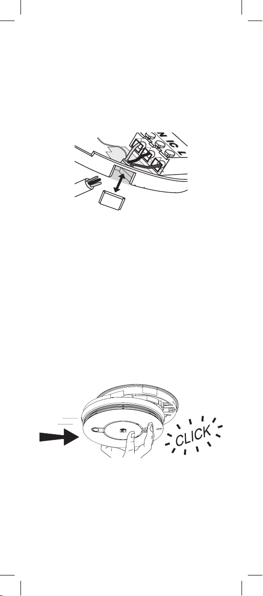
(b) the mounting plate has a removable section, take it out to
interface directly with 25mm trunking as shown in Figure
3. If interfacing to 16mm trunking carefully cut around
the marked section, leaving the top intact and replace the
section. (If you are not using surface wiring, the removable
section must be left in place for electrical safety reasons).
Figure 3
There are two other positions which are also suitable for the
surface wiring to enter (and exit) the Alarm, one next to the
removable section and another directly opposite.
5. Screw the mounting plate into place. Connect the wires to the
terminal block. With recessed wiring, ensure the rear gasket
seals around the edge of the hole in the ceiling or wall. This is
to prevent air draughts affecting the smoke/heat entering the
Alarm. If the hole is too large or the Alarm does not seal it, it
should be sealed with silicone rubber or equivalent.
6. Replace the wiring cover.
7. Attach the battery to the battery snaps.
8. Carefully line up the Alarm on the mounting plate and slide
on (see Figure 4).
Figure 4
Slide on the Alarm
9. Press and hold the Test/hush button for 10 seconds. The horn
will sound. On release of the button, the local Alarm will stop
sounding immediately and the interconnected Alarms will
stop sounding a few seconds later.
10. Connect the mains power to the Alarm circuit. The red LED
will flash once and the green LED will light up. Ensure the
green LED remains lit confirming that the Alarm is receiving
mains power.
7
Page 8
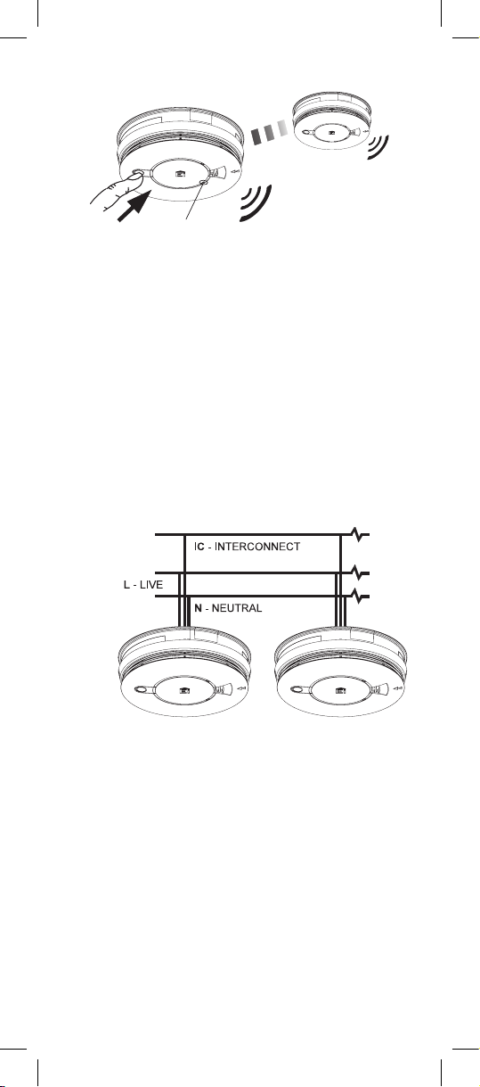
Figure 5
Test Alarms
Green LED
Power Indicator
Interconnecting Alarms
With interconnected Alarms, when one Alarm detects fire all will
sound. However, only Alarms detecting fire will have a flashing
red LED.
Heat Alarms must always be interconnected to Smoke Alarms to
ensure early warning.
WARNING: Do not hardwire interconnect mains powered
Alarms with low voltage or battery powered Ei Electronics
Alarms/devices or any other type of Alarm produced by another
manufacturer. Doing so may damage the Alarms and could result
in a shock or fire hazard.
To interconnect Alarms connect all the IC terminals together as
shown in Figure 6.
Figure 6
The interconnect wire (minimum 0.75mm2 cable) must be treated
as if it was Live. It should be insulated and sheathed.
A maximum of 250 metres of wire can be used (maximum
resistance between detectors 50 Ohms).
Alarms should be interconnected only within the confines of a
single family living unit.
The Alarm can also be RF interconnected to other RF Alarms and
devices by installing an Ei168RC RF base.
8
Page 9

Removing Alarms
Locate removal slot
Insert screwdriver
Slide Alarm off mounting plate
Remove Alarm
With the screwdriver still inserted, push the lower
half of the Alarm away from the screwdriver, it the
direction of the arrows on the cover
Hold the lower half of the Alarm and remove from
the mounting plate by lowering the Alarm towards
the floor
Insert a flat-bladed screwdriver horizontally
about 10mm into the centre of the removal slot
Locate the arrow on the front face of the Alarm.
The slot is located directly above
WARNING: Disconnect mains before removal
9
Page 10
Disposal of Alarms
The crossed out wheelie bin symbol that is on your
product indicates that this product should not be disposed
of via the normal household waste stream. Proper
disposal will prevent possible harm to the environment or
to human health. When disposing of this product please
separate it from other waste streams to ensure that it can
be recycled in an environmentally sound manner. For
more details on collection and proper disposal, please
contact your local government office or the retailer where
you purchased this product.
Ei Electronics, Shannon, Co. Clare, Ireland Ei Electronics, Shannon, Co. Clare, Ireland
Nominal activation conditions/ sensitivity,
response delay (response time) and
performance under fire condition
Pass
Operational reliability Pass
Tolerance to voltage supply Pass
Response delay and temperature resistance Pass
Vibration resistance Pass
Humidity resistance Pass
Corrosion resistance Pass
Electrical stability Pass
21
DoP 21-0002
EN14604:2005 + AC:2008
Smoke Alarm Devices:
Ei146e
Fire Safety
2797
The Declaration of Performance may be consulted at www.eielectronics.com/compliance
Heat Alarm Devices:
Ei144e
21
Heat Alarm Devices:
Ei144e
DoP No. 21-0002
0086
The Alarm must be recycled in accordance with the directive
2012/19/EU on waste electrical & electronic equipment (WEEE).
DO NOT dispose of your Alarm in a fire.
Contact Us
Aico Ltd. Mile End Business Park,
Maesbury Rd, Oswestry, Shropshire SY10 8NR, U.K.
Ei Electronics. Shannon, V14 H020, Co Clare, Ireland.
Tel: 01691 664100
www.aico.co.uk
Tel:+353 (0)61 471277
www.eielectronics.ie
10
 Loading...