

Dialogic
DMV600BTEC
Media Board
Quick Install Card
Part Number 64-0079-02
Copyright © 2003-2007
Dialogic Corporation.
All Rights Reserved.
Before You Begin
Protecting the Board from Damage
CAUTION: All computer boards are sensitive to
electrostatic discharge (“ESD”). Handle all staticsensitive boards and components at a static-safe
work area, and observe anti-static precautions at all
times.
If you are not familiar with ESD safety precautions,
visit http://www.dialogic.com/support/hwinstall to learn
more.
Unpacking the Board
Unpack the Dialogic® DMV600BTEC Media Board
(“board”) according to the following steps:
1. Prepare a static-safeguarded work area.
2. Carefully remove the board from the shipping
carton and anti-static packaging. Handle the
board by the edges and avoid touching the
board’s components.
3. Lay the board on the static-dissipative work
surface.
Note: Place boards in static-shielding bags when
carrying boards from station to station.
CAUTION: Do not remove the board from the antistatic packaging until you are ready to install it.
Observe proper anti-static precautions at all times.
Installing the Hardware
Note: For a new installation, you should install the
hardware before installing the system software. If you
are adding boards to an existing system, there is no
need to uninstall or reinstall the software.
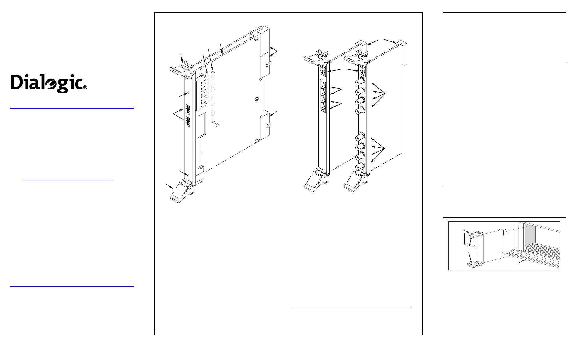
Physical Description
7
6
4
3
2
1
4
1. Out of Service LED: Indicates board is out of service or
in reset from host.
2. Alarm/Status LEDs: During power-up, indicate Power
On Self Test (POST) status. During operation, the top
two sets of LEDs indicate status and alarms for the two
trunks (the bottom two sets of LEDs are unused):
Red–Indicates loss of clock on incoming line from
external network.
Yellow–Indicates loss of frame synchronization at far
end of external network.
Carrier Signal–Indicates board is powered up and
receiving signal from external T1 or E1 source.
Loopback–Indicates the T1 or E1 network is in loopback
mode.
3. Power LED
4. Board Extractor (with red locking tab)
5. Global Memory Module
6. Signal Processor Daughterboard connector
7. Signal Processor Daughterboard
8. J1, J4, J5: Board connector to CompactPCI backplane.
J1 key conforms to PICMG universal hot swap.
5
CompactPCI
POWER
1
A
2
L
A
RED
R
YEL
M
CARR
S
SGNL
LOOP
/
BACK
3
S
4
T
A
RED
T
YEL
U
CARR
S
SGNL
LOOP
BACK
OUT OF
SERVICE
CompactPCI Baseboard Rear I/O Modules
12
8
E
11
T
H
E
R
N
E
T
J1
10
J2
Not
8
RJ48C
(T1 and 120-Ohm E1)
Used
9. BNC Connectors (T1, R1, T2, R2,): Connectors to
external 75-Ohm E1 digital telephone network interfaces.
(Connectors T3, R3, T4, and R4 are not used in this
assembly.)
10. RJ48C Connectors (J1, J2): Connectors to external T1
or 120-Ohm E1 digital telephone network interfaces.
(Connectors J3 and J4 are not used in this assembly.)
11. Ethernet Connector: The Ethernet connectors are not
functional on this assembly.
12. J5: Rear I/O module connector to CompactPCI
backplane.
The default configuration of the Rear I/O Modules provides
loopback connection (signals to the board are looped back to
the source) when the board is powered off and during board
initialization. To disable loopback mode on either trunk,
remove the shunts from the indicated jumper pins:
RJ48C I/O module BNC I/O module
Trunk 1 JP1 & JP2 JP100 & JP101
Trunk 2 JP3 & JP4 JP200 & JP201
E
T
H
E
R
N
E
T
T1
R1
T2
R2
BNC
(75-Ohm E1)
9
Not
Used
CAUTION: This document provides instructions for
installing the DMV600BTEC in a “cold” (power off)
system, most of which also apply to live insertion or
hot swap systems. It is important to note that there
are additional, system-dependent considerations for
live insertion. See the Administration Guide for your
Dialogic
®
System Software release for detailed
information on live insertion.
1. Work at a static-safe area. Turn the power to the
chassis OFF if you do not have a live insertion
system. If you have live insertion capability, the
power to the chassis can remain ON.
2. Remove the chassis cover plate or open the door
on both the front and back of the chassis.
3. Select an empty slot and remove the slot’s access
cover plates (if applicable).
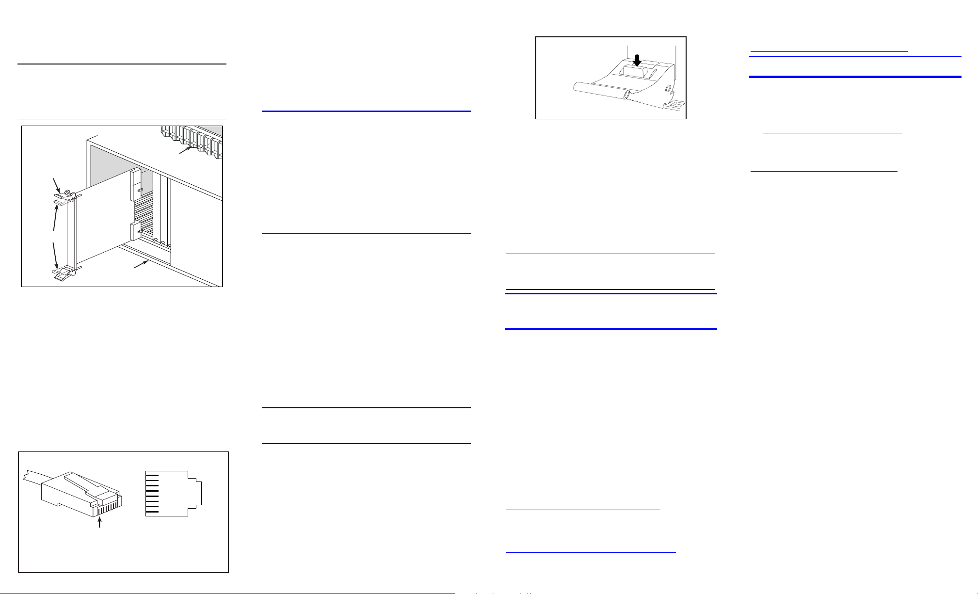
Installing the Rear I/O Module
Note: If you are installing hardware in a live insertion
system with the power on, you should install the rear
I/O module before the baseboard.
4. Install the I/O module in the rear of the selected
slot. Use the slot’s board guides as you insert the
board into the chassis slot. Make sure the tabs on
the board extractors engage the guide holes in the
chassis card cage, then lock down the board
extractors until the red locking tabs snap shut.
CAUTION: CompactPCI backplane pins are easily
bent. Make sure that the board connectors are
mating properly with hand pressure before fully
seating the board. When using the board extractors
to seat the board, make sure to seat evenly.
Installing Rear I/O Module
Unlocked
Position
Locked
Position
Rear I/O
Module
CompactPCI
Chassis (Rear)
Backplane
Installing the Baseboard
Note: If you are installing hardware in a live insertion
system with the power on, you should install the rear
I/O module before the baseboard.
5. Install the baseboard in the front of the selected
slot. Use the slot’s board guides as you insert the
board into the chassis slot. Make sure the tabs on
the board extractors engage the guide holes in the
chassis card cage, then lock down the board
extractors until the red locking tabs snap shut.
Note: If the power to the chassis is on when you
insert the board, power is immediately applied to
the board, the Out of Service LED lights briefly and
then goes out, and the Power LED goes on.
CAUTION: CompactPCI backplane pins are easily
bent. Make sure that the board connectors are
mating properly with hand pressure before fully
seating the board. When using the board extractors
to seat the board, make sure to seat evenly.
Installing cPCI Baseboard
Compact PCI
Unlocked
Position
Locked
Position
Compact PCI
Baseboard
Compact PCI
Chassis
Backplane
External Connections
6. For an RJ48C (T1 or 120-Ohm E1) I/O module,
connect the external digital telephone cables to the
RJ-48C jacks on the board bracket. The topmost
RJ-48C jack is for trunk 1 and the second jack is
for trunk 2. The pinout for the RJ48C connectors is
given in the following figure
7. For a BNC (75-Ohm E1) rear I/O module, connect
the external digital telephone cables to the BNC
connectors. The top two BNC connectors (T1 and
R1) are for trunk 1, and the next two connectors
(T2 and R2) are for trunk 2.
RJ48C Connector Pinout
Network Interface
Cable Connector
Pin 1
Pinout for RJ–48C Jacks
on Rear I/O Module
8
7
6
5
4
3
2
1
Chassis Ground
8
Chassis Ground
7
Unused
6
XMIT_TIP
5
XMIT_RING
4
Unused
3
RCV_TIP
2
RCV_RING
1
Completing the Installation
8. Select a new slot and repeat steps 3-7 for each
board you are installing.
9. Replace the front and back cover plate or close
the front and back chassis doors, as appropriate.
CompactPCI Board Extractor
Press and hold dow n
the red locking tabs on
both bo ard extractors
before applying
pressure to the board
e xtr a cto r s
10. If the power to the chassis was turned OFF in step
1, turn the power to the chassis ON.
After Installing the Hardware
For a new installation, proceed with the software
installation as described in the Dialogic
®
System
Software documentation.
Note: If you are adding hardware to an existing
telecom system, you do not need to uninstall or
reinstall existing Dialogic
®
System Software.
For technical specifications and product information
go to:
http://www.dialogic.com/products.htm.
Removing the Hardware
Exercise caution when removing boards from a
CompactPCI chassis. The board extractors are
equipped with red locking tabs that latch when the
board is correctly positioned in the chassis.
Attempting to extract a board without first releasing
the locks may break the lock mechanism.
Removing the Rear I/O Module
Note: In a live insertion (powered-on) system, do not
remove and replace a rear I/O module while the
baseboard is in service. Remove the front board first,
then remove and replace the rear I/O module, and
then reinsert the baseboard.
To remove the rear I/O module from the chassis,
simultaneously press down both red locking tabs on
the extractors (see the figure above) then evenly
press the extractors away from the center of the
module to release the module from the chassis.
CAUTION: If the red locking tabs on the extractors
are not pressed before applying pressure to the
extractors, there is a risk of breaking the tabs.
Warranty and Return
Information
Removing the Baseboard
Before removing the baseboard, ensure that you are
properly grounded. To remove the baseboard from
the chassis, simultaneously press down both red
locking tabs on the extractors (see the figure below),
then evenly press the extractors away from the center
For specific warranty information for this board, refer
to the Warranty section of the Products page, located
at this URL: http://www.dialogic.com/warranties/.
of the board to release the board from the chassis.
CAUTION: If the red locking tabs on the extractors
are not pressed before applying pressure to the
extractors, there is a risk of breaking the tabs.
After removing the baseboard, immediately place it on
a static-safe work surface or insert it into an anti-static
container.
Contacting Technical Support
Dialogic provides technical support for its products
through a network of value added distributors who are
trained to answer technical questions on installing and
configuring Dialogic® products. If you are unsure how
to contact your support channel, please call Dialogic
in the United States at 973-967-6600 (9am-5pm EST)
and we will assist in obtaining the appropriate support
channel. Outside the United States refer to
http://www.dialogic.com/support/contact to obtain
local contact information. Dialogic also provides direct
support via Dialogic
more details of direct support from Dialogic refer to:
http://www.dialogic.com/support/DialogicPro.
Warranty Period
®
Pro™ Services agreements. For
Returning a Product
To return a board for warranty repair or any other
returns, please refer to the following:
http://www.dialogic.com/support/hwfaults.
Sales Assistance
If you have a sales question, please contact your
local Sales Representative or the Regional Sales
Office for your area. Address, telephone and fax
numbers, are available at the Dialogic website located
at: http://www.dialogic.com/contact.htm
To purchase Dialogic® products, please refer to the
following website to locate the appropriate supplier:
http://www.dialogic.com/purchase.htm.
All contents of this document are furnished for informational use only and are
subject to change without notice and do not represent a commitment on the part of
Dialogic Corporation or its subsidiaries (“Dialogic”). Reasonable effort is made to
ensure the accuracy of the information contained in the document. However,
Dialogic does not warrant the accuracy of this information and cannot accept
responsibility for errors, inaccuracies or omissions that may be contained in this
document.
INFORMATION IN THIS DOCUMENT IS PROVIDED IN CONNECTION
WITH DIALOGIC
ESTOPPEL OR OTHERWISE, TO ANY INTELLECTUAL PROPERTY
RIGHTS IS GRANTED BY THIS DOCUMENT. EXCEPT AS PROVIDED IN A
SIGNED AGREEMENT BETWEEN YOU AND DIALOGIC, DIALOGIC
ASSUMES NO LIABILITY WHATSOEVER, AND DIALOGIC DISCLAIMS
ANY EXPRESS OR IMPLIED WARRANTY, RELATING TO SALE AND/OR
USE OF DIALOGIC PRODUCTS INCLUDING LIABILITY OR
WARRANTIES RELATING TO FITNESS FOR A PARTICULAR PURPOSE,
MERCHANTABILITY, OR INFRINGEMENT OF ANY INTELLECTUAL
PROPERTY RIGHT OF A THIRD PARTY.
Dialogic products are not intended for use in medical, life saving, life sustaining,
critical control or safety systems, or in nuclear facility applications.
It is possible that the use or implementation of any one of the concepts,
applications, or ideas described in this document, in marketing collateral produced
by or on web pages maintained by Dialogic may infringe one or more patents or
other intellectual property rights owned by third parties. Dialogic does not provide
any intellectual property licenses with the sale of Dialogic products other than a
license to use such product in accordance with intellectual property owned or
validly licensed by Dialogic and no such licenses are provided except pursuant to a
signed agreement with Dialogic. More detailed information about such intellectual
property is available from Dialogic’s legal department at 9800 Cavendish Blvd., 5
Floor, Montreal, Quebec, Canada H4M 2V9. Dialogic encourages all users of its
products to procure all necessary intellectual property licenses required to
implement any concepts or applications and does not condone or encourage
any intellectual property infringement and disclaims any responsibility
related thereto. These intellectual property licenses may differ from country
to country and it is the responsibility of those who develop the concepts or
applications to be aware of and comply with different national license
requirements.
Dialogic, Diva, Eicon, Eicon Networks, Eiconcard, Dialogic Pro and SIPcontrol,
among others, are either registered trademarks or trademarks of Dialogic.
Dialogic's trademarks may be used publicly only with permission from Dialogic.
Such permission may only be granted by Dialogic’s legal department at 9800
Cavendish Blvd., 5th Floor, Montreal, Quebec, Canada H4M 2V9. Any authorized
use of Dialogic's trademarks will be subject to full respect of the trademark
guidelines published by Dialogic from time to time and any use of Dialogic’s
trademarks requires proper acknowledgement. The names of actual companies and
products mentioned herein are the trademarks of their respective owners.
®
PRODUCTS. NO LICENSE, EXPRESS OR IMPLIED, BY
.
th
 Loading...