


Mains Powered
Ei3024 / 3016 / 3014
Alarms
Instruction Manual
Read and retain carefully for as long as the product is being used. It contains vital information on the operation and installation of your Alarm. The leaflet should be regarded as part of the product.
If you are just installing the unit, the leaflet MUST be given to the householder. The leaflet is to be given to any subsequent user.

Contents
Installer Guide |
4 |
||
1. |
Introduction |
4 |
|
|
1.1 |
Overview |
6 |
|
1.2 |
Technical Specifications |
8 |
2. |
Installation |
10 |
|
|
2.1 |
Important Safety Instructions |
11 |
|
2.2 |
Where to locate the Alarm? |
12 |
|
2.3 |
Which Alarm in what room? |
16 |
|
2.4 |
Where in the room? |
18 |
|
2.5 |
Locations to avoid |
19 |
|
2.6 |
Mounting and wiring |
21 |
|
2.7 |
Interconnecting Alarms |
25 |
|
2.8 |
Removing the Alarm |
27 |
2

User Guide |
28 |
||
3. Testing |
28 |
||
|
3.1 |
Testing and maintaining your Alarm |
29 |
|
3.2 |
Cleaning your Alarm |
31 |
4. |
What to do in case of alarm |
33 |
|
5. |
Troubleshooting and Indicator summary tables |
35 |
|
6. |
Important safeguards |
43 |
|
7. |
Service and Guarantee |
46 |
|
|
7.1 |
Getting your Alarm serviced |
47 |
|
7.2 |
Guarantee |
47 |
3

Installer Guide
1
Introduction
4

The Ei3024 is a Multi-Sensor Fire Alarm with heat enhanced optical smoke sensor and automatic dust compensation, delivering a faster response to a wider range of fires. It detects both smoke and heat from a fire and is ideal for hallway, landing, living room and bedroom areas.
The Ei3016 is an Optical Smoke Alarm, with a proven optical sensor and automatic dust compensation delivering a fast response to smouldering fires. It is ideal for hallway, landing and living room areas.
The Ei3014 is a Heat Alarm with a Class A1 heat detection sensor. It can only to be used as part of a fire detection system, i.e. interconnected with Ei Electronics mains powered Multi-Sensor Fire or Smoke Alarms. It is ideal for kitchens, garages, boiler houses and other areas where there are normally high levels of fumes, smoke or dust i.e. places where Smoke Alarms cannot be installed without the risk of excessive nuisance alarms.
Up to 12 Alarms can be interconnected so that if one senses fire, all Alarms sound. It can be a hardwired interconnection, a wireless interconnection or a mixture of both (for the wireless option an Ei3000MRF SmartLINK module needs to be added to each Alarm – sold separately).
The Ei3000 series is supplied with a mounting plate that allows very quick and simple installation of the Alarm. The mains and battery power is automatically connected as the Alarm slides onto the mounting plate. Each Alarm comes with built-in rechargeable backup batteries to power the Alarm in the event of a mains failure.
AudioLINK
The Ei3000 series Alarms are AudioLINK enabled. This feature allows the user to download information from the Alarm through the use of a mobile App. For more information on using this feature, please refer to the relevant section on www.eielectronics.com or www.aico.co.uk.
5
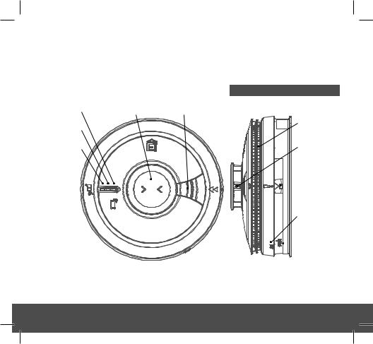
1.1 Overview
Ei3024 Multi-Sensor Fire Alarm
Green LED |
Test / Hush Button |
Alarm Sounder |
Power Indicator |
|
|
Yellow LED |
|
|
Fault Indicator |
|
|
Red LED |
|
|
Alarm Indicator |
|
|
Smoke Entry
Vents
Heat Sensor (Thermistor)
Alarm
Removal
 Latch
Latch
RF Module
LED Indicator
RF Module
 Learn Switch
6
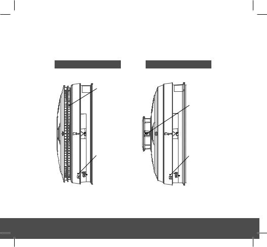
Ei3016 Optical Alarm
Smoke Entry
Vents
Alarm
Removal
 Latch
Latch
RF Module
LED Indicator
RF Module
 Learn Switch
Ei3014 Heat Alarm
Heat Sensor (Thermistor)
Alarm
Removal
 Latch
Latch
RF Module
LED Indicator
RF Module
 Learn Switch
7

1.2 Technical Specifications
Optical Sensor
Heat Sensor
Power Supply
Battery Backup
Alarm Sounder
Alarm Sound Level
Memory Feature
Self Test
Test/Hush Button
Visual indicators
AudioLINK
Operational Life
Interconnection
Optical (Ei3024 and Ei3016)
Thermistor Class A1 Detection (Ei3014 and Ei3024)
100-250V AC, 50Hz, 0.25W
Built-in 10-year rechargeable Vanadium Pentoxide Lithium cells. Fully charged, the battery will provide up to 6 months (without module fitted) or 3 months (with module fitted) back-up without mains power
Piezoelectric Horn
85dB(A) at 3 meters (min)
Indicates that the Alarm has previously detected fire
Sensors, batteries and electronics are automatically tested periodically
Checks sensors, electronics, interconnection and sounder.
If the unit is in alarm when pressed, it silences the alarm for 10min
Green LED – Power supply Yellow LED – Fault, EOL
Red LED – Memory or alarm (if coincides with horn sounding)
Enabled
10 years
Up to 12 units can be interconnected via a hardwired or wireless system (using optional Ei3000MRF SmartLINK module)
8

Technical Specifications
Fixings
Operating Temperature
Humidity Range
Plastic Material
Dimensions
Weight
Warranty
Approvals
Supplied with Easi-fit anti-tamper mounting plate with integral terminal block and wiring cover, includes screws and wall plugs
Normal: 0°C to +40°C (Storage: 0°C to +40°C)*
15% to 95% RH (non-condensing)
UL94V-0 flame retardant rated
Ei3024 and Ei3014: Product: - Ø150mm x 66mm
Package - 155mm x 155mm x 70mm
Ei3016: Product: - Ø150mm x 63mm
Package - 155mm x 155mm x 65mm
350g (including packaging)
5 year (limited)
KM522831
KM83678
EN14604:2005+AC 2008
BS5446-2:2003
*Temperature and Humidity conditions are for normal operation and storage. Units will function outside these ranges as required by the specific product Standards. Extended exposure to conditions outside these ranges can reduce product life. For advice on prolonged operation outside these ranges consult the manufacturer.
9

2
Installation
10
2.1 Important Safety Instructions
Mains operated Alarms should be installed and interconnected by a qualified electrician in accordance with the local appropriate Regulations for Electrical Installations. Failure to install this Alarm correctly may expose the user to shock or fire hazards and damage the product.
The Alarm is designed to be permanently mounted, using its own built-in terminal block to connect it to the mains. The mounting plate can be screwed directly to the ceiling. Alternatively, it can be screwed to a standard junction box (BS 4662 single gang accessory box). It requires a typical current of 3mA. The Alarm must not be exposed to dripping or splashing. There are important markings on the underside of the Alarm.
Alternative Energy Sources - (Wind, Solar, UPS etc.)
This product is designed to be connected to a Pure or True Sine Wave 230V AC supply.
If connecting to a power source that utilises an inverter, e.g. PV solar panel, the Total Harmonic Distortion (THD) must be less than 5%. If in doubt please check with the manufacturer of the inverter. This also applies to battery powered UPS (Uninterruptible Power Supply) inverters.
Light Dimmer Circuits – The Alarms must not be powered from a light dimmer circuit.
Do not install Alarms in new or renovated buildings until all work is completed.
The Alarm must not be connected when the house wiring insulation is being checked with high voltages. i.e. Do not use a high voltage insulation tester on the Alarm.
11

The Alarm must be continuously powered 24 hours a day so it is important that it is not on a circuit that can be turned off by a switch.
(UK) BS 5839-6: 2013 gives the following recommendations regarding the mains supply to be used in a Grade D system. The power supply for the Alarms should be derived from the public electricity supply to the dwelling. The mains supply to the Alarms should take the form of either:
(a)an independent circuit at the dwelling’s main distribution board, in which case no other electrical equipment should be connected to this circuit (other than a dedicated monitoring device installed to indicate failure of the mains supply to the Alarms); or
(b)a separately electrically protected, regularly used local lighting circuit.
Alarms should be connected on a single final circuit, unless the means of interconnection is by radio signals (e.g. RadioLINK). (See BS 5839-6: 2013 for further information)
(IRE) Please refer to ET101: 2008: National Rules for Electrical Installations
2.2 Where to locate the Alarm
The advice here follows the guidance in British Standard BS 5839-Part 6:2013 and IS 3218:2013 in general (for further information refer to the relevant standards).
The main reason for fitting Smoke/Heat/Multi-Sensor Alarms in dwellings is to ensure that when there is a fire, sufficient early warning is given so that everybody can escape safely. This means that the fire Alarms should ideally be located near all potential sources of fires and that the alarm should be heard throughout the house – particularly in the bedrooms.
It is also important that nuisance/false alarms are minimised to ensure the Alarms are not disabled or ignored.
12

A single Smoke Alarm will give some protection if it is properly installed, but most homes will require two or more to ensure that a reliable early warning is given. For recommended protection you should put individual Smoke Alarms in all rooms where fire is most likely to break out (apart from the kitchen and bathroom).
BS 5839-Part 6:2013 and IS 3218:2013 give guidance on:
-how many Alarms to install
-what type of Alarm to use
-where to position Alarms
The above points will depend on the type of dwelling to be protected and the level of fire risk.
Fire Risk Assessment
The ‘Grade’ and ‘Category’ of system that should be installed depends on the fire risk. It is therefore recommended that a Fire Risk Assessment is undertaken. The Risk Assessment would be based on a combination of probabilities:
-fire occurring
-injury or death to occupant
-system operating correctly with a fire
-early detection and warning to occupants in the event of a fire.
The greater the risks, the more comprehensive and reliable systems needs to be.
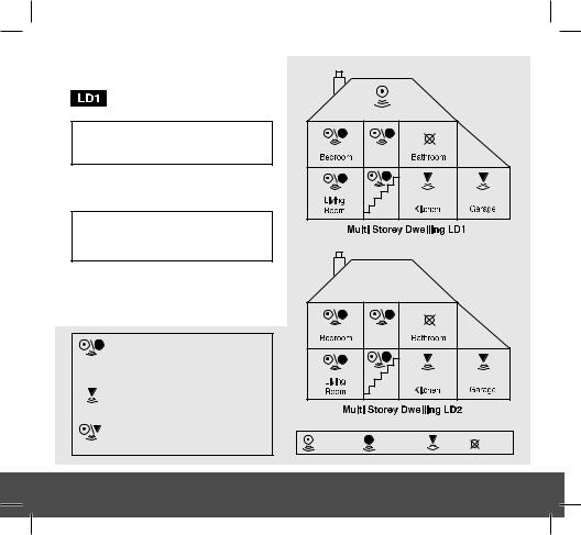
LD (Life protection in Dwellings) Systems define the level of fire protection required for households, depending on the fire risk and regulations. Ei Electronics recommends that an LD1 system be installed for optimum protection.
Please see following pages for detailed information.
13

UK Requirements (BS 5839-6:2013)
OPTIMUM PROTECTION
for dwellings where occupants may be at high risk (e.g. elderly)
Optimum Protection LD1: As LD2, but in addition Smoke or Heat Alarms should be located in all rooms and other areas of the dwelling.
(apart from toilets or bathroom)
Interconnect all Alarms
 BASIC PROTECTION
for new or materially altered dwellings or existing dwellings with poor structural fire precautions
Basic Protection LD2: Smoke or Heat Alarms in all rooms or areas that present a high fire risk to occupants. (apart from toilets or bathroom)
Interconnect all Alarms
 MINIMUM PROTECTION
Minimum Protection LD3: Alarms in all hallways, stairways and circulation areas that form part of the escape routes from the dwelling.
Multi-Sensor or Smoke Alarms located:
 on each storey
 every 7.5 m of hallways and escape routes
 within 3m of all bedroom doors (apart from toilets & bathrooms
  )
)
Heat Alarms located in:  each Kitchen
(Heat Alarms must be within 5.3m of potential fire sources)
Multi-Sensor or Heat Alarms located in:  each Living room (i.e. most frequently used daytime room)
Multi-Sensor |
Optical |
Heat |
do not |
Fire Alarm |
Smoke Alarm |
Alarm |
fit Alarm |
14
ROI Requirements (IS 3218:2013)
OPTIMUM PROTECTION
for dwellings where occupants may be at high risk (e.g. elderly)
Optimum Protection LD1: As LD2, but also including attics / lofts / other spaces in which a fire might start (apart from toilets or bathroom).
Interconnect all Alarms
 BASIC PROTECTION
for new or materially altered dwellings or existing dwellings with poor structural fire precautions
Basic Protection LD2: all circulation areas that form part of an escaper route within the dwelling, and all high fire risk areas / rooms e.g. kitchen, living rooms, garages and all bedrooms (apart from toilets or bathroom).
Interconnect all Alarms
Multi-Sensor or Smoke Alarms located:
 on each storey
 every 7.5 m of hallways and escape routes
 within 3m of all bedroom doors (apart from toilets & bathrooms
  )
)
Heat Alarms located in:  each Kitchen
(Heat Alarms must be within 5.3m of potential fire sources)
Multi-Sensor or Heat Alarms located in:  each Living room (i.e. most frequently used daytime room)
Multi-Sensor |
Optical |
Heat |
do not |
Fire Alarm |
Smoke Alarm |
Alarm |
fit Alarm |
15

2.3 Which Alarm in what room?
Location |
Ei3024 |
Ei3016 |
Ei3014 |
|
Mutil-Sensor |
Optical |
Heat |
|
Fire Alarm |
Smoke Alarm |
Alarm (i) |
|
|
|
|
Hall, Corridors, Escape routes |
|
|
|
|
|
|
|
Kitchens / Garages |
|
|
(iii) |
|
|
|
|
Living Rooms |
|
|
(ii) |
|
|
|
|
Bedrooms |
|
|
|
|
|
|
|
Shower / Bathrooms |
|
|
|
(i)A Heat Alarm should only be used in a room adjoining an escape route, in conjunction with Multi-Sensor Fire Alarms or Smoke Alarms on the escape routes. All the Alarms should be interconnected to ensure the early warning will be heard.
(ii)Some Fire authorities (concerned with the slow response of Heat Alarms) advise that Multi-Sensor Fire Alarms or Smoke Alarms should be fitted in living rooms. This is acceptable according to BS 5839-6 provided there are clearly not going to be problems with nuisance alarms. Fit Heat Alarms only if nuisance alarms are very likely and it is acceptable that a warning will only be given by the Heat Alarm when there is a very significant flaming fire in the room. If the door(s) and windows are not closed to contain the fire and heat, it is extremely unlikely that the Heat Alarm would respond before a Multi-Sensor Fire Alarm or Smoke Alarm sited outside in the corridor.
(iii)In enclosed kitchens with doors closed.
16
 Loading...