


ASSEMBLY ISTRUCTIONS
Mod. VECTOR 70
Mod. VECTOR 80
GB
MC
advanced mobular stair system
Code MD.K.001 Rev 01 Edition 04.2008

advanced mobularstairsystem
- VECTOR 70 - VECTOR 80 -
CONTENTS
Structureof the manual .......................................... Pag. 2
PART 1. ................................................................. Pag. 3
Wooden components VECTOR 70 - VECTOR 80. “ 3
Components VECTOR 70 - VECTOR 80. ............ “ 4
PART 2. ................................................................. Pag. 7
Configuration VECTOR 70 - VECTOR 80 . .......... “ 7
Usefulheightmeasurement.................................... “ 8
Calculatingthe tread............................................... “ 9
Calculating the rise.......................................... “ 10
Configuration.......................................................... “ 13
Configuration “L”. ................................................ “ 13
Configuration “U”................................................. “ 14
Traking ................................................................... “. 16
Preparing columns and steps................................. “ 17
Assembling the steps............................................. “ 18
Mounting the column and bracket..........................“ 25
Checking and mounting additional columns........... “ 28
Assembling the handrail ......................................... “ 29
Assembling handrail cables ................................... “ 31
Completion and checks .......................................... “ 32
STRUCTURE OF THE MANUAL
The present assembly instructions are sub-divided into two sections as follows:
Part 1
-All the parts included in the package are listed and illustrated:
woodencomponents listed in progressive order, the letter“L” preceding thenumber.
The partscomposingthe VECTOR 70 - VECTOR 80 models are identifiedby a number preceded by the letters
“K”“B”“P”.
Part 2
-the preliminaryoperations and various stages for a correctprocedure are listed.
The assemblystages of steps, banister columns and handrail shared by both models are illustrated.
Via C.Colombo, 22/A - 42046 - Reggiolo - Reggio Emilia - Italy
- 2 -
Tel. +39 - 0522-97 32 34 - Fax +39 - 0522-97 31 39
ehleva@ehleva.it
By Mobirolo S.p.A.
VECTOR 70 - VECTOR 80

advanced mobularstairsystem
PART 1
WOODEN COMPONENTS Mod. VECTOR 70 - VECTOR 80
Before proceeding to the various assembly stages, empty the cardboard package and arrange all parts on a flat
surface to check that all components included in the list attached are present, that the number of components
matches the indications of both the “L” and “U” configurations of the stairs and that no damaged parts are present.
- VECTOR 70 - VECTOR 80 -
Stair shape
Ref. Draw N. pcs. Ref. Draw N. pcs.
L15 5 5
L20 9 6
L21 1 2
L23 1 2
D03 1 1
D04 1 1
Stair shape
L22 1 2
Via C.Colombo, 22/A - 42046 - Reggiolo - Reggio Emilia - Italy
VECTOR 70 - VECTOR 80
Tel. +39 - 0522-97 32 34 - Fax +39 - 0522-97 31 39
ehleva@ehleva.it
By Mobirolo S.p.A.
- 3 -

advanced mobularstairsystem
COMPONENTS Mod. VECTOR 70 - VECTOR 80
- VECTOR 70 - VECTOR 80 -
Ref. Draw N. pcs.
M6x70
M6x6
Ø6x12
K18 1 1
K23 5 5
K133 1 1
Ref. Draw N. pcs.
K63 11 9
1125 mm
Ø 22 mm
K65 12 10
K66 30 30
K36 6 8
K38 1 1
K60 32 48
K84 Length.6500 mm 7 7
K68 4 6
K71 5 5
K76 4 6
K77 7 9
4.2x19
K80 30 30
K82 1 2
- 4 -
Via C.Colombo, 22/A - 42046 - Reggiolo - Reggio Emilia - Italy
Tel. +39 - 0522-97 32 34 - Fax +39 - 0522-97 31 39
ehleva@ehleva.it
By Mobirolo S.p.A.
VECTOR 70 - VECTOR 80

advanced mobularstairsystem
Ref. Draw N. pcs. Ref. Draw N. pcs.
K100 2 2
K122 1 1
K101 10 10
- VECTOR 70 - VECTOR 80 -
K102 1 1
K103 1 1
K104 11 11
K119 11 11
K120 11 11
K123 1 1
K125 1 2
1100mm
Ø 22 mm
K126 11 11
M16x30
K127 11 11
K121 1 1
Via C.Colombo, 22/A - 42046 - Reggiolo - Reggio Emilia - Italy
VECTOR 70 - VECTOR 80
Tel. +39 - 0522-97 32 34 - Fax +39 - 0522-97 31 39
ehleva@ehleva.it
By Mobirolo S.p.A.
K129 2 2
- 5 -

advanced mobularstairsystem
- VECTOR 70 - VECTOR 80 -
Ref. Draw N. pcs. Ref. Draw N. pcs.
K130 2 2
K131 8 8
B200 4 4
B201 2 2
B202 1 1
B207 2 2
P90 1 1
P105 23 23
P106a 22 22
P106 143 143
B203 23 23
B204 12 12
B205 48 48
M10x40
B206 1 1
Via C.Colombo, 22/A - 42046 - Reggiolo - Reggio Emilia - Italy
- 6 -
Tel. +39 - 0522-97 32 34 - Fax +39 - 0522-97 31 39
ehleva@ehleva.it
By Mobirolo S.p.A.
P107 23 23
P110 3 5
B300 1 1
B301 1 1
VECTOR 70 - VECTOR 80

advanced mobularstairsystem
PART 2
CONFIGURATION VECTOR 70 - VECTOR 80
These are called “modular stairs” because the rise “A” and tread “P” may be adjusted according to the availabe
space.
The “VECTOR 70” label identifies the stairmodel having a 700 mm stepwidth
The “VECTOR 80” label identifies the stair modelhaving a 800 mm stepwidth.
The type and instructions for a correct assembly are identical.
Before passing on to the assembly instructions, the correct configuration must be established.
The staircase may lean on a wall or be placed in an openenvironment.
In the first case, thebanister will be mounted only on the inner side oppositethe wall, and the gangway size may be
derivedfrom figureb.
If the banister needs to be mounted on both sides, the gangwayis highlighted in fig. a.
Moreover, the locationand available space determine the climbing directions, which may be right- or left-oriented,
andthe actualstaircase configuration, accordingto an “L-”or“U-”shapedconfiguration,asillustratedinthe following
pages.
- VECTOR 70 - VECTOR 80 -
Mod. VECTOR 70 Width. 740 mm
Mod. VECTOR 80 Width. 840 mm
VECTOR 70 - 700
VECTOR 80 - 800
VECTOR 70 - 785
VECTOR 80 - 885
10 - 40 mm
Fig.a Fig.b
VECTOR 70 - 742.5
VECTOR 80 - 842.5
VECTOR 70 - 700
VECTOR 80 - 800
VECTOR 70 - VECTOR 80
Via C.Colombo, 22/A - 42046 - Reggiolo - Reggio Emilia - Italy
Tel. +39 - 0522-97 32 34 - Fax +39 - 0522-97 31 39
ehleva@ehleva.it
By Mobirolo S.p.A.
- 7 -

advanced mobularstairsystem
USEFUL HEIGHT MEASUREMENT
- VECTOR 70 - VECTOR 80 -
The measures that need to be assessed are
reported infig. 1.
“A” Rise size to be defined based on
“Table “A” on pages 9-10-11
“P” Treadsize, calculatedaccording
to the instructions reported on page 8
“H” Height(fig. 2)
N.B. All measures reportedin the manual are
in “mm” (millimetres)
Measure the distance between upper and lower
floor“H”.
The measure assessed thanksto this operation
playsanimportant role since it sets the rise size.
The size “H” needs to be identified in the
dedicated box of “table A” on pages 9-10-11.
After having identified the “H” height, the
adjacentboxes report the rise value “A”andhow
many steps are needed to achieve the desired
height. (Fig. 2)
However, follow the detailed explanation on the
followingpages.
P
A
Fig.1
H
- 8 -
Via C.Colombo, 22/A - 42046 - Reggiolo - Reggio Emilia - Italy
Tel. +39 - 0522-97 32 34 - Fax +39 - 0522-97 31 39
ehleva@ehleva.it
By Mobirolo S.p.A.
Fig.2
VECTOR 70 - VECTOR 80

advanced mobularstairsystem
CALCULATING THE TREAD
The treadmaybe calculatedaccordingtothefollowingformulas,referringtobothVECTOR70- VECTOR80 staircase
models.
In case of the “L” configuration, only the formula 1 shall be applied and all steps will have the same tread size; in
case of the “U” configuration, the formula 1 shall be applied for the W stretch, whereas the formula 2 shall be
implemented for the J tread.Consequently, two different treadsizes mayemerge,one for the J and Q stretches and
onefor theW stretch. Please notice that the values of the VECTOR 70 model mustrange between 200 mm min and
230 mm max, whereas those of the VECTOR 80 model must range between 220 mm min and 250 mm max.
P = Tread
W = Staircase length with“L” configuration
J = Staircasewidthwith“U” configuration
WARNING
The measures to be reported in the documents below must be expressed in millimetres.
- VECTOR 70 - VECTOR 80 -
Formula 1
VECTOR 70 Config. “L” e “U” P =
Formula 2
VECTOR 70 Config. “U” P =
J - 1460
Config.
“L”
Right
W
Q
n° G
W - 990
n° G - 1
n° G
Formula 1
VECTOR 80 Config. “L” e “U” P =
Formula 2
VECTOR 80 Config. “U” P =
Config.
“U”
Right
W
J
W - 1110
n° G - 1
J - 1660
n° G
n° G
Left
VECTOR 70 - VECTOR 80
L
n° G
Left
Via C.Colombo, 22/A - 42046 - Reggiolo - Reggio Emilia - Italy
Tel. +39 - 0522-97 32 34 - Fax +39 - 0522-97 31 39
ehleva@ehleva.it
By Mobirolo S.p.A.
Q
Fig.c
- 9 -

advanced mobularstairsystem
CALCULATING THE RISE (table “A”)
The “table A” below shows the values for the rise according to the “H” height measured previously. Moreover the
number of K106 spacers to be mounted is reported, also with referenceto theheight.
How to read and use the table: example. Measured height: “H” 2390 mm
The 2390 line shows that the staircase will be composed of 12 steps and that 7 180 mm rises and 5 185 mm rises
need to be created (the first rise is always 205 mm).
To create the rises described above, a spacer packagemust be installed including:
four spaces (two P106a with rounded corners and two normal P106) to achieve the 180 mm rise
five spacers (two P106a with roundedcorners and three normalP106) to achieve the 185 mm rise
- VECTOR 70 - VECTOR 80 -
Spacer number 4 5 6 7 8
Alzata
Rise “A” Rise “A”
H. G. 180 185 190 195 200
2365 12 12
2370 12 11 1
2375 12 10 2
2380 12 9 3
2385 12 8 4
2390 12 7 5
2395 12 6 6
2400 12 5 7
2405 12 4 8
2410 12 3 9
2415 12 2 10
2420 12 1 11
2425 12 12
2430 12 11 1
2435 12 10 2
2440 12 9 3
2445 12 8 4
2450 12 7 5
2455 12 6 6
2460 12 5 7
2465 12 4 8
2470 12 3 9
2475 12 2 10
2480 12 1 11
2485 12 12
2490 12 11 1
2495 12 10 2
2500 12 9 3
2505 12 8 4
2510 12 7 5
2515 12 6 6
2520 12 5 7
2525 12 4 8
2530 12 3 9
2535 12 2 10
2540 12 1 11
2545 12 12
2550 12 11 1
2555 12 10 2
2560 12 9 3
2565 12 8 4
2570 12 7 5
2575 12 6 6
2580 12 5 7
2585 12 4 8
2590 12 3 9
2595 12 2 10
2600 12 1 11
- 10 -
Via C.Colombo, 22/A - 42046 - Reggiolo - Reggio Emilia - Italy
Tel. +39 - 0522-97 32 34 - Fax +39 - 0522-97 31 39
Spacer number 8 9 10 11 12
H. G. 200 205 210 215 220
2605 12 12
2610 12 11 1
2615 12 10 2
2620 12 9 3
2625 12 8 4
2630 12 7 5
2635 12 6 6
2640 12 5 7
2645 12 4 8
2650 12 3 9
2655 12 2 10
2660 12 1 11
2665 12 12
2670 12 11 1
2675 12 10 2
2680 12 9 3
2685 12 8 4
2690 12 7 5
2695 12 6 6
2700 12 5 7
2705 12 4 8
2710 12 3 9
2715 12 2 10
2720 12 1 11
2725 12 12
2730 12 11 1
2735 12 10 2
2740 12 9 3
2745 12 8 4
2750 12 7 5
2755 12 6 6
2760 12 5 7
2765 12 4 8
2770 12 3 9
2775 12 2 10
2780 12 1 11
2785 12 12
2790 12 11 1
2795 12 10 2
2800 12 9 3
2805 12 8 4
2810 12 7 5
2815 12 6 6
2820 12 5 7
2825 12 4 8
2830 12 3 9
2835 12 2 10
2840 12 1 11
ehleva@ehleva.it
By Mobirolo S.p.A.
Alzata
VECTOR 70 - VECTOR 80

advanced mobularstairsystem
- VECTOR 70 - VECTOR 80 -
Spacer number 12 13 14 15
Alzata
Rise “A” Rise “A”
H. G. 220 225 230 235
2845 12 12
2850 12 11 1
2855 12 10 2
2860 12 9 3
2865 12 8 4
2870 12 7 5
2875 12 6 6
2880 12 5 7
2885 12 4 8
2890 12 3 9
2895 12 2 10
2900 12 1 11
2905 12 12
2910 12 11 1
2915 12 10 2
2920 12 9 3
2925 12 8 4
2930 12 7 5
2935 12 6 6
2940 12 5 7
2945 12 4 8
2950 12 3 9
2955 12 2 10
2960 12 1 11
2965 12 12
2970 12 11 1
2975 12 10 2
2980 12 9 3
2985 12 8 4
2990 12 7 5
2995 12 6 6
3000 12 5 7
3005 12 4 8
3010 12 3 9
3015 12 2 10
3020 12 1 11
3025 12 12
Spacer number 11 12 13 14
Alzate
Rise “A”
H. G. 215 220 225 230
3030 13 7 6
3035 13 6 7
3040 13 5 8
3045 13 4 9
3050 13 3 10
3055 13 2 11
3060 13 1 12
3065 13 13
3070 13 12 1
3075 13 11 2
3080 13 10 3
3085 13 9 4
3090 13 8 5
3095 13 7 6
3100 13 6 7
3105 13 5 8
3110 13 4 9
Spacer number 11 12 13 14 15
Alzata
H. G. 215 220 225 230 235
3115 13 3 10
3120 13 2 11
3125 13 1 12
3130 13 13
3135 13 12 1
3140 13 11 2
3145 13 10 3
3150 13 9 4
3155 13 8 5
3160 13 7 6
3165 13 6 7
3170 13 5 8
3175 13 4 9
3180 13 3 10
3185 13 2 11
3190 13 1 12
3195 13 13
3200 13 12 1
3205 13 11 2
3210 13 10 3
3215 13 9 4
3220 13 8 5
3225 13 7 6
3230 13 6 7
3235 13 5 8
3240 13 4 9
3245 13 3 10
3250 13 2 11
3255 13 1 12
3260 13 13
Spacer number 11 12 13 14
Alzate
Rise “A”
H. G. 215 220 225 230
3265 14 4 10
3270 14 3 11
3275 14 2 12
3280 14 1 13
3285 14 14
3290 14 13 1
3295 14 12 2
3300 14 11 3
3305 14 10 4
3310 14 9 5
3315 14 8 6
3320 14 7 7
3325 14 6 8
3330 14 5 9
3335 14 4 10
3340 14 3 11
3345 14 2 12
3350 14 1 13
3355 14 14
3360 14 13 1
3365 14 12 2
3370 14 11 3
3375 14 10 4
VECTOR 70 - VECTOR 80
Via C.Colombo, 22/A - 42046 - Reggiolo - Reggio Emilia - Italy
Tel. +39 - 0522-97 32 34 - Fax +39 - 0522-97 31 39
ehleva@ehleva.it
By Mobirolo S.p.A.
- 11 -
advanced mobularstairsystem
- VECTOR 70 - VECTOR 80 -
Spacer number 11 12 13 14 15
Rise “A” Rise “A”
Alzata
H. G. 215 220 225 230 235
3380 14 9 5
3385 14 8 6
3390 14 7 7
3395 14 6 8
3400 14 5 9
3405 14 4 10
3410 14 3 11
3415 14 2 12
3420 14 1 13
3425 14 14
3430 14 13 1
3435 14 12 2
3440 14 11 3
3445 14 10 4
3450 14 9 5
3455 14 8 6
3460 14 7 7
3465 14 6 8
3470 14 5 9
3475 14 4 10
3480 14 3 11
3485 14 2 12
3490 14 1 13
3495 14 14
Spacer number 11 12 13 14 15
Alzata
H. G. 215 220 225 230 235
3645 15 2 13
3650 15 1 14
3655 15 15
3660 15 14 1
3665 15 13 2
3670 15 12 3
3675 15 11 4
3680 15 10 5
3685 15 9 6
3690 15 8 7
3695 15 7 8
3700 15 6 9
3705 15 5 10
3710 15 4 11
3715 15 3 12
3720 15 2 13
3725 15 1 14
3730 15 15
Spacer number 11 12 13 14
Alzate
Rise “A”
H. G. 215 220 225 230
3500 15 1 14
3505 15 15
3510 15 14 1
3515 15 13 2
3520 15 12 3
3525 15 11 4
3530 15 10 5
3535 15 9 6
3540 15 8 7
3545 15 7 8
3550 15 6 9
3555 15 5 10
3560 15 4 11
3565 15 3 12
3570 15 2 13
3575 15 1 14
3580 15 15
3585 15 14 1
3590 15 13 2
3595 15 12 3
3600 15 11 4
3605 15 10 5
3610 15 9 6
3615 15 8 7
3620 15 7 8
3625 15 6 9
3630 15 5 10
3635 15 4 11
3640 15 3 12
- 12 -
Via C.Colombo, 22/A - 42046 - Reggiolo - Reggio Emilia - Italy
Tel. +39 - 0522-97 32 34 - Fax +39 - 0522-97 31 39
ehleva@ehleva.it
By Mobirolo S.p.A.
VECTOR 70 - VECTOR 80

advanced mobularstairsystem
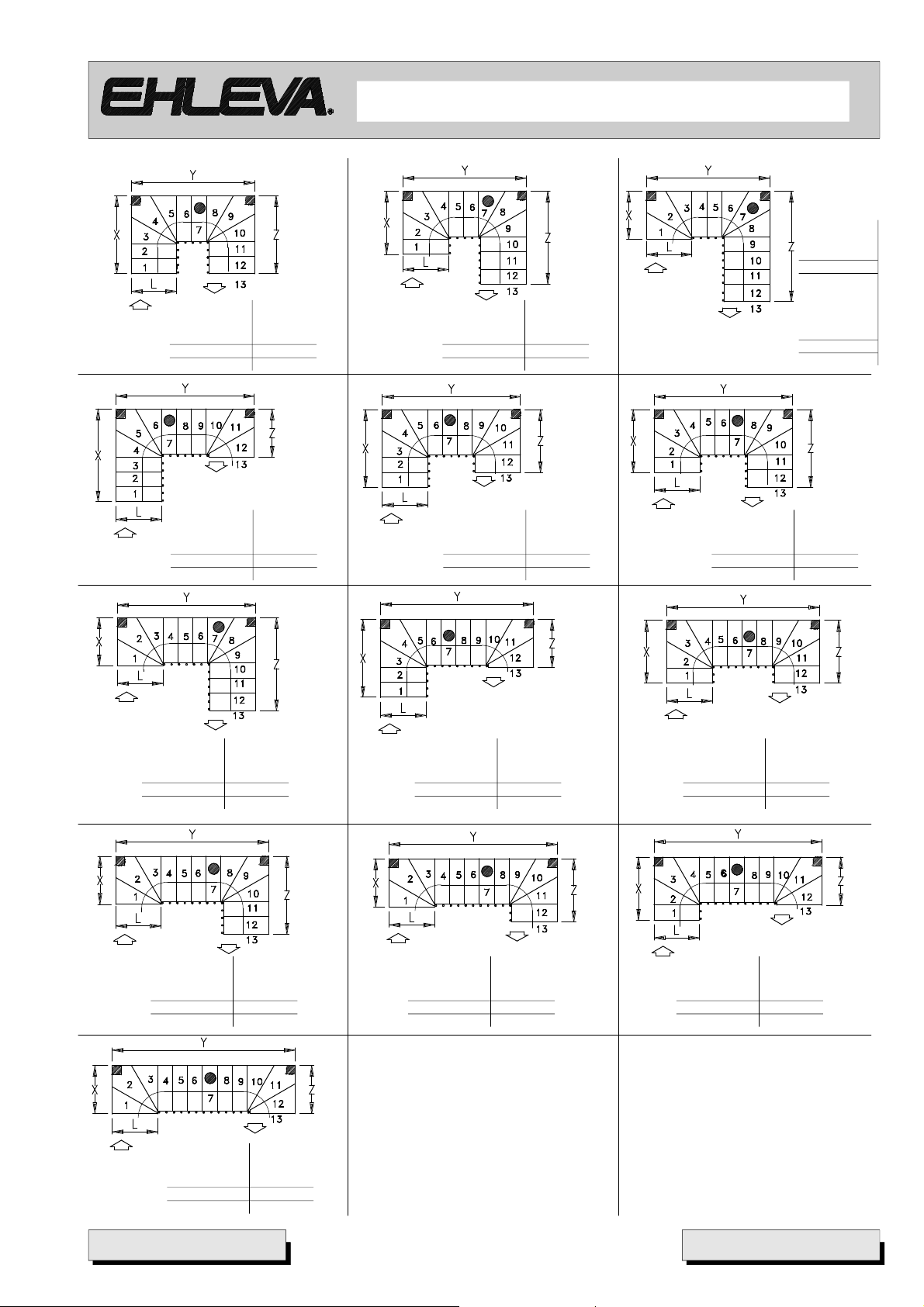
CONFIGURATION
Theavailable configurations and their relevant sizes are reported below.Please noticethat, for brevity’s sake, only
right-climbing staircases are illustrated.Each of the drawings presented ismatched by its left-climbingcounterpart.
Moreover,the points where the staircase can be anchored or supportedduringtheassemblystagesare also shown.
Wall anchoringpoint Wall anchoring point Support point
CONFIGURATION “L”
- VECTOR 70 - VECTOR 80 -
VEC. 70 VEC. 80
L=740 L=840
X 740 840
Z 2580-2820 2840-3100
VEC. 70 VEC. 80
L=740 L=840
X 1340-1430 1500-1590
Z 1980-2130 2200-2350
VEC. 70
L=740
X 1940-2120
Z 1380-1440
VEC. 70 VEC. 80
L=740 L=840
X 940-970 1060-1090
Z 2390-2600 2640-2850
VEC. 70 VEC. 80
L=740 L=840
X 1540-1660 1720-1840
Z 1780-1900 1980-2100
VEC. 70
L=740
X 2140-2350
Z 1180-1210
VEC. 70 VEC. 80
L=740 L=840
X 1140-1200 1280-1340
Z 2180-2360 2420-2600
VEC. 70 VEC. 80
L=740 L=840
X 1740-1890 1940-2090
Z 1580-1670 1760-1850
VEC. 70
L=740
X 2340-2580
Z 980
X 2160-2340
Z 1540-1600
X 2540-2810
Z 750
X 2820-3090
Z 850
VECTOR 70 - VECTOR 80
VEC. 80
L=840
VEC. 70
L=740
VEC. 80
L=840
VEC. 80
L=840
X 2380-2590
Z 1320-1350
H
Z
X
Via C.Colombo, 22/A - 42046 - Reggiolo - Reggio Emilia - Italy
Tel. +39 - 0522-97 32 34 - Fax +39 - 0522-97 31 39
By Mobirolo S.p.A.
L
ehleva@ehleva.it
Z
VEC. 80
L=840
X 2060-2840
Z 1100
L
H
Y
X
- 13 -

advanced mobularstairsystem
CONFIGURATION “U”
- VECTOR 70 - VECTOR 80 -
VEC. 70
L=740
X 1940-2120
Y 1440
Z 750
VEC. 80
L=840
X 2160-2340
Y 1640
Z 850
VEC. 70
L=740
X 1340-1430
Y 1440
Z 1380-1440
VEC. 80
L=840
X 1500-1590
Y 1640
Z 1540-1600
VEC. 70
L=740
X 740
Y 1440
Z 1980-2130
VEC. 80
L=840
X 840
Y 1640
Z 2200-2350
VEC. 70
L=740
X 1740-1890
Y 1440
Z 980
VEC. 80
L=840
X 1940-2090
Y 1640
Z 1100
VEC. 70
L=740
X 1140-1200
Y 1440
Z 1580-1670
VEC. 80
L=840
X 1280-1340
Y 1640
Z 1760-1850
VEC. 70
L=740
X 1740-1890
Y 1640-1670
Z 750
VEC. 80
L=840
X 1940-2090
Y 1860-1890
Z 850
VEC. 70
L=740
X 1540-1660
Y 1440
Z 1180-1210
VEC. 80
L=840
X 1720-1840
Y 1640
Z 1320-1350
VEC. 70
L=740
X 940-970
Y 1440
Z 1760-1880
VEC. 80
L=840
X 1060-1090
Y 1640
Z 1990-2100
VEC. 70
L=740
X 1540-1660
Y 1640-1670
Z 980
VEC. 80
L=840
X 1720-1840
Y 1860-1890
Z 1100
- 14 -
VEC. 70
L=740
X 1340-1430
Y 1640-1670
Z 1180-1210
VEC. 80
L=840
X 1720-1590
Y 1860-1890
Z 1320-1350
VEC. 70
L=740
X 740
Y 1640-1670
Z 1780-1900
VEC. 80
L=840
X 840
Y 1860-1890
Z 1980-2100
Via C.Colombo, 22/A - 42046 - Reggiolo - Reggio Emilia - Italy
VEC. 70
L=740
X 1140-1200
Y 1640-1670
Z 1380-1440
VEC. 80
L=840
X 1280-1340
Y 1860-1890
Z 1540-1600
VEC. 70
L=740
X 1540-1660
Y 1840-1900
Z 750
VEC. 80
L=840
X 1720-1840
Y 2080-2140
Z 850
Tel. +39 - 0522-97 32 34 - Fax +39 - 0522-97 31 39
ehleva@ehleva.it
By Mobirolo S.p.A.
VEC. 70
L=740
X 940-970
Y 1640-1670
Z 1580-1670
VEC. 80
L=840
X 1060-1090
Y 1860-1890
Z 1760-1850
VEC. 70
L=740
X 1340-1430
Y 1840-1900
Z 980
VEC. 80
L=840
X 1500-1590
Y 2080-2140
Z 1100
VECTOR 70 - VECTOR 80
advanced mobularstairsystem
- VECTOR 70 - VECTOR 80 -
VEC. 70
L=740
X 740
Y 840-1900
Z 1580-1670
VEC. 70 VEC. 80
L=740 L=840
X 1140-1200 1280-1340
Y 1840-1900 2080-2140
Z 1180-1210 1320-1350
VEC. 70 VEC. 80
L=740 L=840
X 1340-1430 1500-1590
Y 2040-2130 2300-2390
Z 750 850
VEC. 70 VEC. 80
L=740 L=840
X 740 840
Y 2040-2130 2300-2390
Z 1380-1440 1540-1600
VEC. 70 VEC. 80
L=740 L=840
X 940-970 1060-1090
Y 1840-1900 2080-2140
Z 1380-1440 1980-2100
VEC. 70 VEC. 80
L=740 L=840
X 1140-1200 1280-1340
Y 2040-2130 2300-2390
Z 980 1100
VEC. 70 VEC. 80
L=740 L=840
X 1140-1200 1280-1340
Y 2240-2360 2520-2640
Z 750 850
VEC. 80
L=840
X 840
Y 2080-2140
Z 1760-1850
VEC. 70 VEC. 80
L=740 L=840
X 940-970 1060-1090
Y 2040-2130 2300-2390
Z 1180-1210 1320-1350
VEC. 70 VEC. 80
L=740 L=840
X 940-970 1060-1090
Y 2240-2360 2520-2640
Z 980 1100
VEC. 70 VEC. 80
L=740 L=840
X 740 840
Y 2240-2360 2520-2640
Z 1180-1210 1320-1350
VEC. 70 VEC. 80
L=740 L=840
X 740 840
Y 2640-2820 2960-3140
Z 750 850
VECTOR 70 - VECTOR 80
VEC. 70 VEC. 80
L=740 L=840
X 740 840
Y 2440-2590 2740-2890
Z 980 1100
VECTOR 70 = VEC. 70
VECTOR 80 = VEC. 80
Via C.Colombo, 22/A - 42046 - Reggiolo - Reggio Emilia - Italy
Tel. +39 - 0522-97 32 34 - Fax +39 - 0522-97 31 39
ehleva@ehleva.it
By Mobirolo S.p.A.
VEC. 70 VEC. 80
L=740 L=840
X 940-970 1060-1090
Y 2440-2590 2740-2890
Z 750 1100
- 15 -

advanced mobularstairsystem
TRAKING
Afterhavingidentifiedandsetthe parametersidentifying
the staircase characteristics (H height,P tread and A
rise) assembly operations can actually start.
Alwaysbegin from the arrivalposition.
- VECTOR 70 - VECTOR 80 -
On the arrival floor slab, the correct position must be
identified toanchor the step support.
Position the D03 template on the floor slab, make sure
it is aligned with the floor (use a level) and comply with
thefollowingreferences:
value V = 260mm min. for the VECTOR 70 model
(sidewithout banister)
310mmmin.fortheVECTOR80model(side
withoutbanister)
value A = corresponding to the value of the “A” rise
calculatedpreviously.
The D03 template includes six holes. To anchor the
module, two holes areenough.
Identifytheholesthatneedtobereproduced:in general
refer to those halfway the floor slab width,not too close
to the floor surface. fig. 3.
V
Vector 70= min. 260 mm
Vector 80= min. 310 mm
m
0 m
5
1
Ø
D03
1
6
A
Fig.3
- 16 -
K129
Via C.Colombo, 22/A - 42046 - Reggiolo - Reggio Emilia - Italy
Tel. +39 - 0522-97 32 34 - Fax +39 - 0522-97 31 39
ehleva@ehleva.it
By Mobirolo S.p.A.
Fig.4
K103
Fig.5
VECTOR 70 - VECTOR 80

advanced mobularstairsystem
PREPARING COLUMNS AND STEPS
Before proceeding to assemble the steps, mount the
- VECTOR 70 - VECTOR 80 -
P107 banister column support fig. 7 -8 - 9 - 10.
Drill a Ø4 hole by means of a wood drill in the points
identified on the step and achieve a 30 mm depth as
shown in fig. 9.
WARNING!!!
Be very careful when operating on the bottom side
of the step, where anchoring holes are already
present, and on the correct side where the banister
will be mounted.
Mount columns as shown in fig. 6
K66
st
1
nd
2
P107
20 mm
Fig.7
P107
K80
K65
K63
Length. 1125 mm
Fig.8
Ø4
30mm
Fig.9
L20
VECTOR 70 - VECTOR 80
B203
Fig.6
Via C.Colombo, 22/A - 42046 - Reggiolo - Reggio Emilia - Italy
Tel. +39 - 0522-97 32 34 - Fax +39 - 0522-97 31 39
ehleva@ehleva.it
By Mobirolo S.p.A.
Fig.10
- 17 -

advanced mobularstairsystem
ASSEMBLING THE STEP
- VECTOR 70 - VECTOR 80 -
L20
B205
At this point form the P106 - P106a spacer
package which will determine the size of the
rise set previously.
To define the numberof spacers to be used,
refer to the “table A” attached to the pages
9-10-11.
Form the spacer packagebyassemblingthe
P106 - P106a spacers as shown in fig. 12.
Insert the K120 plate into the K101 support
module and maintain its position by means
of the D04 template as shownin fig. 12.
Screw the K104 pin into the K120plate
described aboveas shown in fig. 12
P107
Fig.11
P106a
K104
P106
K120
P106a
K101
D04
Fig.12
- 18 -
Via C.Colombo, 22/A - 42046 - Reggiolo - Reggio Emilia - Italy
Tel. +39 - 0522-97 32 34 - Fax +39 - 0522-97 31 39
ehleva@ehleva.it
By Mobirolo S.p.A.
VECTOR 70 - VECTOR 80

advanced mobularstairsystem
Havingformedaunit,inserttheprojectingpart
of the pin into the hole placed under the step
supportmodulemountedpreviously. Insertthe
K119 plate into the pipe of the unit described
aboveandanchoreverythingby means of the
K127 screw and theK126 washer.
To facilitate screwing operations, we
recommend using a jack spanner to screw in
the screw until it starts tightening. Since the
tread must stillbe adjusted, theunit must not
be tightened fully.
Moreover, before assembling the module,
insert theP105 plug from behind.
(fig.13)
- VECTOR 70 - VECTOR 80 -
K127
K126
K119
P105
Now adjust the moduleaccording to the “P”
tread size.
Thisvaluemustbemeasuredstartingfrom the
front part of the spacer package until the
reference present on the support flange as
shown in fig. 14.
Fully tighten the K127 screw which was
previouslyleft lose, payingparticularattention
to the position of the spacer package, which
needs to remain aligned with the support.
The use of a rigid reference guide is
recommended to be applied to the sides of
the pipe with clamps during the operation.
Assemble the L20 step on the K101 support
by means of the B205 screws as shown in
fig. 15.
K101
Fig.13
P
Fig.14
VECTOR 70 - VECTOR 80
L20
B205
Via C.Colombo, 22/A - 42046 - Reggiolo - Reggio Emilia - Italy
Tel. +39 - 0522-97 32 34 - Fax +39 - 0522-97 31 39
ehleva@ehleva.it
By Mobirolo S.p.A.
Fig.15
- 19 -

advanced mobularstairsystem
Insert the K63 columninto the P107 support
mountedpreviously.
By means of a level check that it is vertical
and lock it temporarily in the position
illustrated in fig. 16.
Insert a P107 supportand mark the position
of the holes on the bottom part of the step
fig. 16 -17
- VECTOR 70 - VECTOR 80 -
K63
Drill in the points marked and mount the
P107supportbyfollowingthesameprocedure
illustratedabove.
(fig.7-8-9-10page16)
Fig.16
Fig.17
P107
B203
Ø4
- 20 -
Fig.18
Via C.Colombo, 22/A - 42046 - Reggiolo - Reggio Emilia - Italy
Tel. +39 - 0522-97 32 34 - Fax +39 - 0522-97 31 39
ehleva@ehleva.it
By Mobirolo S.p.A.
B204
VECTOR 70 - VECTOR 80

advanced mobularstairsystem
- VECTOR 70 - VECTOR 80 -
Continue assembling the following steps
according to the same procedure until the first
L21 is achieved where the staircase starts
turning.MounttheP107supportontheL21 step
by using the pre-existing holes and make sure
to insert the square nut with relevant security
dowel as illustrated above. Inset a K63banister
column into the top step support and lock it
temporarily in the position illustrated in fig. 19.
Check that the module is positioned in the P
Max tread position, then place the L21 step as
shown in fig.19 and lock it by means of B205
Adjust the step in the maximum tread position,
i.e.allthewayinthefront,untilthemostadvanced
position is achieved. (fig. 19)
Lock the module in the position achieved and
make sure that during the operation the spacer
package remains aligned with the module,
including thevertical direction of the column.
WARNING!!!
While the steps are being assembled, the
unit that is being formed should be
supported so that it does not press on the
support of spacer package (see the “SUPP.”
example fig. 20). This should be done every
three/four steps (see Example in fig. 20) to
facilitate assembling the starting module
after having reached the ground.
P Max
Vector 70= 230 mm
Vector 80= 250 mm
L21
x
a
m
P
P Min
Vector 70= 200 mm
Vector 80= 220 mm
K63
P107
Fig.19
Similarly, proceed to assemble the L23 central
step.
In this case, the K125 extension should be
mounted and connected to the top rod.
The packagecontains a K125 column.
Cut K125 to achievealength amountingtothree
times the size of the rise T=3*A, and proceed
asshowninfig.20,connectbothpiecesbymeans
of the threaded rod K130 and K23 bushing.
Thestep supporting module
will take the direction set by
theanchoring holes present
in the step.
In this case adjust the “P”
tread until it reaches its
minimumvalue.
Alignthespacerpackageby
means of one of the two
supports and keep it still
while it is being anchored.
K127
K126
K119
L23
SUPP.
B205
K130
K23
n
i
m
P
T=3*A
K125
Fig.20
VECTOR 70 - VECTOR 80
Via C.Colombo, 22/A - 42046 - Reggiolo - Reggio Emilia - Italy
Tel. +39 - 0522-97 32 34 - Fax +39 - 0522-97 31 39
ehleva@ehleva.it
By Mobirolo S.p.A.
- 21 -

advanced mobularstairsystem
- VECTOR 70 - VECTOR 80 -
Similarly, proceed to mount the L22 turning step by
followingthe same procedure described above.
Also in this case, the step must be positioned in the
furthestbackwardpossibletreadposition(P min) (fig.
21)
Anchor the column and extension definitivelyto their
P107 supports, insert the P110 plug into the column
hole as shown in fig. 22.
After havingcompletedtheassemblyof the staircase,
according to the selected configuration, one further
turning step (U configuration) or straight step (L or
wideU configurations)must be inserted.
In either case, the procedure is the same as the
proceduredescribedabove.
Rememberthatif a straightstepismounted,theK101
support modulemust be adjusted again accordingto
the .P. tread as shown in fig. 22.
Complete the assembly of the steps until you reach
theground.
P Min
Vector 70= 200 mm
Vector 80= 220 mm
P
m
i
n
.
L22
B205
Fig.21
P110
P
- 22 -
K101
Via C.Colombo, 22/A - 42046 - Reggiolo - Reggio Emilia - Italy
Tel. +39 - 0522-97 32 34 - Fax +39 - 0522-97 31 39
ehleva@ehleva.it
By Mobirolo S.p.A.
Fig.22
VECTOR 70 - VECTOR 80

advanced mobularstairsystem
After having reached the ground, the K102 element must be used as the last step.
Assemble the module as described above without tightening fully and adjust its position according to the tread.
(fig.24)
P
- VECTOR 70 - VECTOR 80 -
K102
B200
Fig.24
Fig.26
Ø12
Fig.25
B200
Fig.27
Fig.28
VECTOR 70 - VECTOR 80
B205
Via C.Colombo, 22/A - 42046 - Reggiolo - Reggio Emilia - Italy
Tel. +39 - 0522-97 32 34 - Fax +39 - 0522-97 31 39
ehleva@ehleva.it
By Mobirolo S.p.A.
- 23 -

advanced mobularstairsystem
The last column must be cut before being assembled. The cutting length T is calculated according to the formula
reportedinfigure29.
WhereA is the rise value(fig. 29)
T = A - 146 (mm)
K23
- VECTOR 70 - VECTOR 80 -
Fig.29
T
Fig.30
Ø10
Drillthepointmarked by means of a Ø10 drill (fig. 30)
A
After having assembledthe K63 starting column,
mount the K133 stiffener as shown in fig. 31A,
by means of the K36 clamps and position it with
the lower arm under the step
- 24 -
K36
K63
K18
K36
Fig.31
Via C.Colombo, 22/A - 42046 - Reggiolo - Reggio Emilia - Italy
Tel. +39 - 0522-97 32 34 - Fax +39 - 0522-97 31 39
ehleva@ehleva.it
By Mobirolo S.p.A.
K133
Fig.31A
VECTOR 70 - VECTOR 80

advanced mobularstairsystem
MOUNTING THE COLUMN AND/OR BRACKET
WARNING!!!
It is strictly prohibited to use and climb on the stairs before having carried out the stiffening and support
operations.
Moreover,the point wheretoinsert thek122supportColumn must be identified.Thedrawingson12-13-14reportthe
- VECTOR 70 - VECTOR 80 -
points where the staircase may be adequately supported SEE symbol.
Afterhaving identified the position, measure its H1 (mm) height from the floor as shown in fig. 32.
Drill the support from below and in the centre line by means of a Ø12 drill.
SOLUTION 1
Ø12
B206
K123
K122
H1 mm
VECTOR 70 - VECTOR 80
Via C.Colombo, 22/A - 42046 - Reggiolo - Reggio Emilia - Italy
Tel. +39 - 0522-97 32 34 - Fax +39 - 0522-97 31 39
ehleva@ehleva.it
By Mobirolo S.p.A.
Fig.32
- 25 -

advanced mobularstairsystem
- VECTOR 70 - VECTOR 80 -
Cut the K122 Column according to the H1 - 10 mm
height(K123 spacer).
(fig.33)
Drill in the marked point by means of a Ø12 drill and
insert the B202 kit small block into the hole
(fig.34-35)
Fig.33
K122
H
1
-
1
0
m
m
B202
Place the Columnback and anchor itbymeansof the
B202 kit screws (fig.36).
Adjust the K123 washer so that it touchesthe bottom
side of the module and join with the B206 screw by
means of the hole drilled before.
(fig.32previouspage)
Tocompletetheoperation,coverallanchoringscrews
(arrivalanddeparturemodules)with theirrelevantK131
caps. In the arrival module, the heads of the screws
must be covered directly, whereas the cap must be
glued on the holes left empty, Fig, 37
Ø12
Fig.34
Fig.35
B202
Fig.36
- 26 -
K131
Via C.Colombo, 22/A - 42046 - Reggiolo - Reggio Emilia - Italy
Tel. +39 - 0522-97 32 34 - Fax +39 - 0522-97 31 39
ehleva@ehleva.it
By Mobirolo S.p.A.
Fig.37
VECTOR 70 - VECTOR 80

advanced mobularstairsystem
In certain cases, no support column may be added, as shown above; in such cases it is advisable to support the
staircase by means of a K121 support bracket to be inserted by drilling a min 150 mm deep hole in the wall closer
to the staircase and embed the bracket as described in fig. 38.
Then mount the P90 closing cap on the pipe head.
SOLUTION 2
- VECTOR 70 - VECTOR 80 -
VECTOR 70 - VECTOR 80
P90
K121
Via C.Colombo, 22/A - 42046 - Reggiolo - Reggio Emilia - Italy
Tel. +39 - 0522-97 32 34 - Fax +39 - 0522-97 31 39
ehleva@ehleva.it
By Mobirolo S.p.A.
1
5
0
Fig. 38
- 27 -

advanced mobularstairsystem
CHECKING AND MOUNTING ADDITIONAL COLUMNS
Nowthe correct positionof the columns assembled needs to be checked. Check that they arevertical and that the
- VECTOR 70 - VECTOR 80 -
cable supports face outside the staircase, as shown in fig. 39
Near the step preceding the first turning step an additional column must be assembled. It must be cut to achieve a
height that is half the rise .A.: T = A / 2
Between the two supports anchoredbefore, trace the position of a third element as shown in fig. 39.
The assemblyprocedure isthe same as the procedure describedabove.
Anchor everything bymeans of the relevant B203 kit screws. Then, insert the P110 cap at the foot of the column.
Mount an additional column on the last step, at a distance equal to the tread size, as shown in fig. 39. Moreover, it
is advisableto assemble an additional support anchored to thetop side of thestep, so thatthe column is anchored
in a stiffer and safer way.
Adjust the height so that it matches those mounted before and does not project beyond its support.
B207
P107
B207
B204
P107
T
=
A
/
2
P110
- 28 -
A
Fig.39
Via C.Colombo, 22/A - 42046 - Reggiolo - Reggio Emilia - Italy
Tel. +39 - 0522-97 32 34 - Fax +39 - 0522-97 31 39
ehleva@ehleva.it
By Mobirolo S.p.A.
VECTOR 70 - VECTOR 80

advanced mobularstairsystem
ASSEMBLING THE HANDRAIL
Placethe handrail on the first support approx. 40-50 mm farfrom thefirst column (fig. 40)
- VECTOR 70 - VECTOR 80 -
By referring to the housing, drill a Ø3 preliminary hole to anchor the handrail in its K65 housing.
Make sure that it is correctlyplaced into its housings, no gaps areleft between them Anchor the handrail by means
of the dedicated K66 kit screw.
Proceed until the last column before the staircase turnshas been reached.
WARNING!!!
When assembling the handrail make sure that the k65 supports shaped like a “saddle” face the inner part
of the staircase.
After having reached the last column before the staircase turns, cutthe handrailand leavetheexceedingpart so that
the K68 plug can be mounted.
We suggest to mount the plug before thefinal anchoring of the handrail on the column.
Resume assemblingthehandrailafterthe staircase has turned by proceedinginthe same way untilreachingthe last
column mountedon the finalstep.
Cut the excessive partof thehandrail andleave a 40-50 mm projectingpart.
All configurationsenvisage that an additional column must bemounted on the last straight step before the staircase
turns. Figure 41 shows the example of a “U” staircase.
L15
B301
K71
L15
K77
L15
4
0
/
5
0
m
m
L15
VECTOR 70 - VECTOR 80
K80
Ø 3
Via C.Colombo, 22/A - 42046 - Reggiolo - Reggio Emilia - Italy
Tel. +39 - 0522-97 32 34 - Fax +39 - 0522-97 31 39
ehleva@ehleva.it
By Mobirolo S.p.A.
K65
Fig. 40
- 29 -

advanced mobularstairsystem
After having assembled the handrail the K68 plug must be mounted at both ends.
Place the plug at one hand and trace the position of the anchoring holes.
Drill with a Ø 4 wood drilland mount the K68 plug with the relevant K76 screw (Fig. 41)
That operation mustbe implemented at both ends of the handrail.
Ø 4
m
m
0
5
/
0
4
- VECTOR 70 - VECTOR 80 -
K68
K76
Ø 4
- 30 -
Via C.Colombo, 22/A - 42046 - Reggiolo - Reggio Emilia - Italy
Tel. +39 - 0522-97 32 34 - Fax +39 - 0522-97 31 39
ehleva@ehleva.it
By Mobirolo S.p.A.
Fig. 41
VECTOR 70 - VECTOR 80

advanced mobularstairsystem
ASSEMBLING THE BANISTER CABLES
Finally, mount the flexible cables.
Proceed as follows:
startingfrom above, insert one endof the K84 cable into theforks mounted on thecolumns and anchor it bymeans
of the relevant K60 clamp.
Continueinsertingthecablesintotherelevantsupportsuntilreachingthe last column, thus completing the banister.
NB. Make sure that the cables are correctly inserted in the relevant supports.
After completing the operation, make sure that the cables are sufficiently tight between columns.
Insert the K60 clamp and anchor it on the cable end; cut the excessive part. Eliminate any scrap or sharp edges
resulting from cutting.
Repeat the same steps with the other stretches of banister.
- VECTOR 70 - VECTOR 80 -
K84
K60
K60
VECTOR 70 - VECTOR 80
Via C.Colombo, 22/A - 42046 - Reggiolo - Reggio Emilia - Italy
Tel. +39 - 0522-97 32 34 - Fax +39 - 0522-97 31 39
ehleva@ehleva.it
By Mobirolo S.p.A.
Fig. 42
- 31 -

advanced mobularstairsystem
COMPLETION AND CHECKS
- VECTOR 70 - VECTOR 80 -
K38
K36
Ø10
K38
K36
K82
K36
Mount the P105 plugs both in the front and back side of the step support modules (fig. 44)
Tass.
Fig. 43
P105
- 32 -
Via C.Colombo, 22/A - 42046 - Reggiolo - Reggio Emilia - Italy
Tel. +39 - 0522-97 32 34 - Fax +39 - 0522-97 31 39
ehleva@ehleva.it
By Mobirolo S.p.A.
P105
Fig. 44
VECTOR 70 - VECTOR 80

advanced mobularstairsystem
After the assemblyoperations have been completed,checkandtest that the staircase is stableandallcomponents
arefirmlyanchored.
As regards the wall anchoring points, refer to the drawings reported on page 12-13-14.
Example of staircase anchoringand supportpoints
bracket application and anchoringpoint K100
pillar staircase support point K122
- VECTOR 70 - VECTOR 80 -
Block
bracket application and anchoringpoint K100
K100
Ø12
B201
B201
Ø6
- 33 -
Via C.Colombo, 22/A - 42046 - Reggiolo - Reggio Emilia - Italy
Tel. +39 - 0522-97 32 34 - Fax +39 - 0522-97 31 39
ehleva@ehleva.it
By Mobirolo S.p.A.
Fig. 45
VECTOR 70 - VECTOR 80
 Loading...