

Page 1
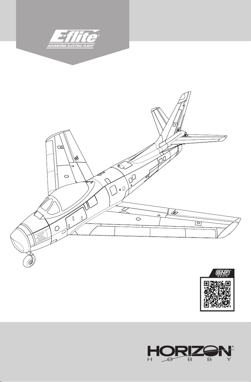
Instruction Manual
Bedienungsanleitung
Manuel d’utilisation
Manuale di Istruzioni
EFLU7050
Created 12/23
Scan the QR code and select the Manuals and Support quick links
from the product page for the most up-to-date manual information.
Scannen Sie den QR-Code und wählen Sie auf der Produktseite
die Quicklinks Handbücher und Unterstützung, um die aktuellsten
Scannez le code QR et sélectionnez les liens rapides Manuals and
Support sur la page du produit pour obtenir les informations les
Scannerizzare il codice QR e selezionare i Link veloci Manuali e
Supporto dalla pagina del prodotto per le informazioni manuali più
Informationen zu Handbücher.
plus récentes sur le manuel.
aggiornate.
EFLU7050
Page 2
EN
NOTICE
All instructions, warranties and other collateral documents are subject to change at the sole discretion of Horizon
Hobby, LLC. For up-to-date product literature, visit horizonhobby.com or towerhobbies.com and click on the support or
resources tab for this product.
MEANING OF SPECIAL LANGUAGE
The following terms are used throughout the product literature to indicate various levels of potential harm when
operating this product:
WARNING: Procedures, which if not properly followed, create the probability of property damage, collateral damage,
and serious injury OR create a high probability of superficial injury.
CAUTION: Procedures, which if not properly followed, create the probability of physical property damage AND a possibility of serious injury.
NOTICE: Procedures, which if not properly followed, create a possibility of physical property damage AND little or no
possibility of injury.
WARNING: Read the ENTIRE instruction manual to become familiar with the features of the product before
operating. Failure to operate the product correctly can result in damage to the product, personal property and
cause serious injury.
This is a sophisticated hobby product. It must be operated with caution and common sense and requires some basic
mechanical ability. Failure to operate this Product in a safe and responsible manner could result in injury or damage
to the product or other property. This product is not intended for use by children without direct adult supervision. Do
not use with incompatible components or alter this product in any way outside of the instructions provided by Horizon
Hobby, LLC. This manual contains instructions for safety, operation and maintenance. It is essential to read and follow
all the instructions and warnings in the manual, prior to assembly, setup or use, in order to operate correctly and avoid
damage or serious injury.
Age Recommendation: Not for children under 14 years. This is not a toy.
Safety Precautions and Warnings
As the user of this product, you are solely responsible for operating in a manner that does not endanger yourself and others or result in damage to the product or the property of others.
• Always keep a safe distance in all directions around
your model to avoid collisions or injury. This model is
controlled by a radio signal subject to interference from
many sources outside your control. Interference can
cause momentary loss of control.
• Always operate your model in open spaces away from
full-size vehicles, traffic and people.
• Always carefully follow the directions and warnings
for this and any optional support equipment (chargers,
rechargeable battery packs, etc.).
• Always keep all chemicals, small parts and anything
electrical out of the reach of children.
• Always avoid water exposure to all equipment not
specifically designed and protected for this purpose.
Moisture causes damage to electronics.
• Never place any portion of the model in your mouth as
it could cause serious injury or even death.
WARNING AGAINST COUNTERFEIT PRODUCTS: If you ever need to replace your Spektrum receiver found in a
Horizon Hobby product, always purchase from Horizon Hobby, LLC or a Horizon Hobby authorized dealer to
ensure authentic high-quality Spektrum product. Horizon Hobby, LLC disclaims all support and warranty with regards,
but not limited to, compatibility and performance of counterfeit products or products claiming compatibility with DSM
or Spektrum technology.
• Never operate your model with low transmitter batteries.
• Always keep aircraft in sight and under control.
• Always use fully charged batteries.
• Always keep transmitter powered on while aircraft is
powered.
• Always remove batteries before disassembly.
• Always keep moving parts clean.
• Always keep parts dry.
• Always let parts cool after use before touching.
• Always remove batteries after use.
• Always ensure failsafe is properly set before flying.
• Never operate aircraft with damaged wiring.
• Never touch moving parts.
2
UMX F-86 Sabre 30mm EDF
Page 3
Registration
Register your product today to join our mailing list and keep up to date with product updates,
offers and E-flite® news.
Specications
Wingspan 17.44" (443mm)
Length 18.3" (466mm)
Weight
Included Equipment
Receiver/ESC Spektrum® Receiver/ESC Unit (SPMA3191)
Motor Brushless Motor: 1010–8300Kv (SPMXAM3200)
Servos Spektrum® A201 2.3g Long-Throw Linear Servo (SPMSA201)
Recommended Equipment
Transmitter Full Range 5+ Channel 2.4GHz w/ Spektrum® DSM2/DSMX® Technology
Battery Spektrum® 450mAh 4S 14.8V 30C LiPo Battery: IC2 (SPMX4504SIC2)
Battery Charger S100 G2 USB-C Smart Charger (SPMXC2090)
Without Battery: 5.9 oz (167g)
With Recommended 4S 450mAh Battery: 7.7 oz (218g)
EN
Table of Contents
Low Voltage Cutoff (LVC) ..................................................4
Transmitter Setup ........................................................4–5
Transmitter and Receiver Binding .....................................6
Smart Technology Telemetry ............................................6
SAFE® Select Technology .............................................6–7
ESC/Receiver Arming and Battery Installation ...................8
Center of Gravity (CG) ......................................................8
Control Direction Test .......................................................9
Control Centering ............................................................9
Control Horn Settings .......................................................9
Flying Tips and Repairs ..................................................10
Hand Launching .............................................................10
Post Flight Checklist ......................................................10
Power Components Service ...........................................11
General Binding Tips and Failsafe BNF
• The included receiver has been specifically programmed for operation of this aircraft. Refer to the
receiver manual for correct setup if the receiver is
replaced.
• Keep away from large metal objects while binding.
• Do not point the transmitter’s antenna directly at the
receiver while binding.
• The orange LED on the receiver will flash rapidly when
the receiver enters bind mode.
Landing Gear .................................................................11
AS3X® System Trouble Shooting Guide ...........................12
Troubleshooting Guide .............................................12–13
Replacement Parts .........................................................14
Recommended Parts ......................................................14
Optional Parts and Accessories ......................................14
Important Federal Aviation Administration
(FAA) Information ........................................................15
AMA National Model Aircraft Safety Code .......................15
Limited Warranty .....................................................15–16
Contact Information .......................................................16
FCC Information .............................................................17
IC Information ................................................................17
Compliance Information for the European Union .............17
• Once bound, the receiver will retain its bind settings for
that transmitter until you re-bind.
• If the receiver loses transmitter communication, the
failsafe will activate. Failsafe moves the throttle channel to low throttle. Pitch and roll channels move to
actively stabilize the aircraft in a descending turn.
• If problems occur, refer to the troubleshooting guide
or if needed, contact the appropriate Horizon Product
Support office.
3
Page 4
EN
Low Voltage Cutoff (LVC)
When a Li-Po battery is discharged below 3V per cell, it
will not hold a charge. The aircraft’s ESC protects the flight
battery from over-discharge using Low Voltage Cutoff (LVC).
Once the battery discharges to 3V per cell, the LVC will
reduce the power to the motor in order to leave adequate
power to the receiver and servos to land the airplane.
When the motor power decreases, land the aircraft immediately and replace or recharge the flight battery.
Always disconnect and remove the Li-Po battery from
the aircraft after each flight. Charge your Li-Po battery to
about half capacity before storage. Make sure the battery
charge does not fall below 3V per cell. Failure to unplug a
connected battery will result in trickle discharge.
For your first flights, set your transmitter timer or a stopwatch to 4 minutes. Adjust your timer for longer or shorter
flights once you have flown the model.
NOTICE: Repeated flying to LVC will damage the battery.
Transmitter Setup
If your transmitter allows it, enable the throttle cut feature.
Always engage throttle cut before approaching the aircraft.
Dual Rates
Low rate is recommended for the initial ights.
NOTICE: To ensure AS3X® technology functions properly,
do not lower rate values below 50%.
NOTICE: If oscillation occurs at high speed, refer to the
Troubleshooting Guide for more information.
NX Series Transmitter Setup
1. Power ON your transmitter, click on scroll wheel, roll to System Setup and click the scroll wheel. Select YES.
2. Go to Model Select and choose Add New Model near the bottom of the list. Select Airplane Model Type by
choosing airplane image, select Create.
3. Set Model Name: Input a name for your model file.
4. Go to Aircraft Type and scroll to the wing selection, choose Wing: 1 Normal Tail: Normal
5. Select Main Screen, Click the scroll wheel to enter the Function List.
6. Go to D/R (Dual Rate) and Expo menu to set D/R and Expo.
7. Set Rates and Expo: Aileron
Set Switch: Switch F
Set High Rates: 100%, Expo 10% — Low Rates: 70%, Expo 5%
8. Set Rates and Expo: Elevator
Set Switch: Switch C
High Rates: 100%, Expo 10% — Low Rates 70%, Expo 5%
9. Set D/R (Dual Rate) and Expo: Rudder
Set Switch: Switch G
High Rates: 100%, Expo 10% — Low Rates 70%, Expo 5%
10. Set Throttle Cut; Switch: Switch H, Position: -100%
Exponential
After your initial flights, you may adjust the exponential
value to better suit your flying style.
Telemetry Alarms
Smart ESC : 12 Pole
Rx V : Min Rx V 4.2V
Smart ESC : Low Voltage Alarm 3.4V
Smart Battery : Startup Volt Minimum 4.0V
4
UMX F-86 Sabre 30mm EDF
Page 5
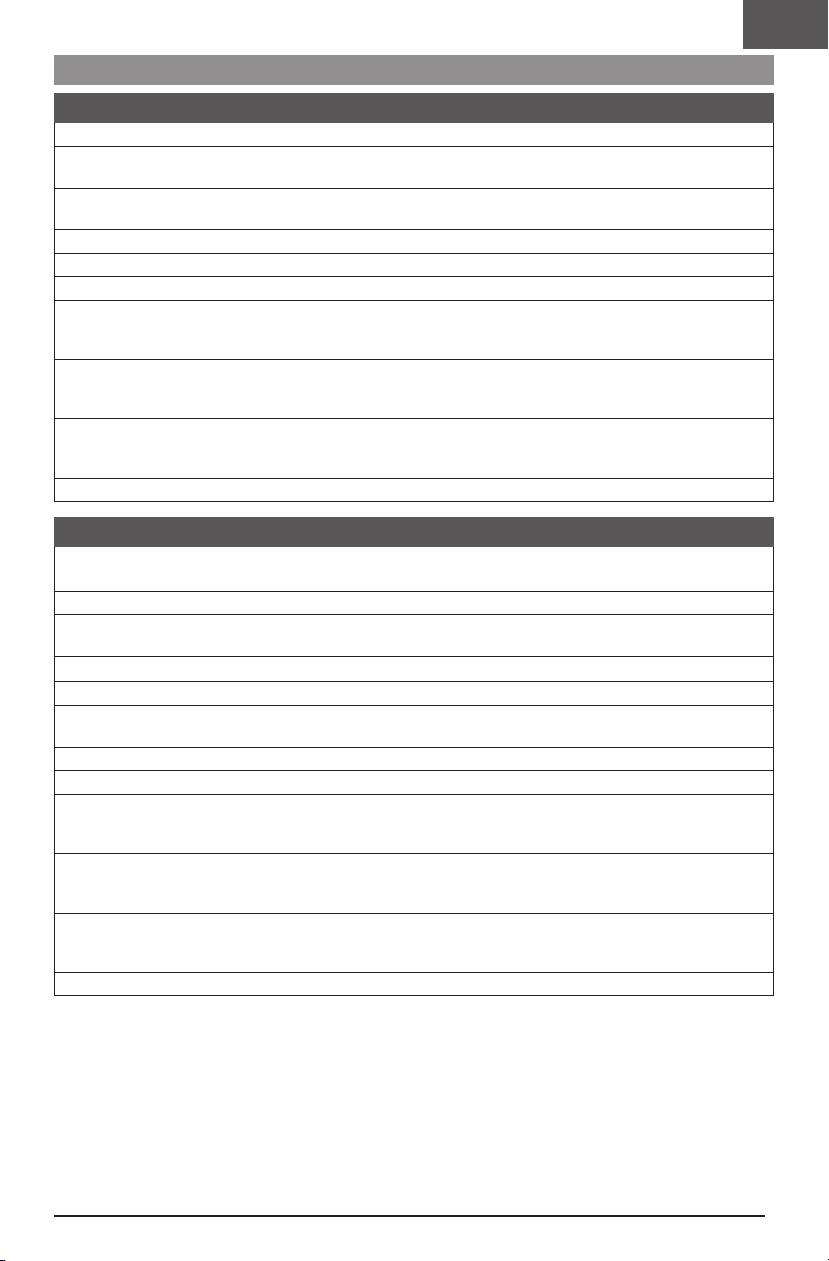
Transmitter Setup
DX Series Transmitter Setup
1. Power ON your transmitter, click on scroll wheel, roll to System Setup and click the scroll wheel. Select YES.
2. Go to Model Select and choose Add New Model at the bottom of the list.
The system asks if you want to create a new model, select Create.
3. Set Model Type: Select Airplane Model Type by choosing the airplane.
The system asks you to confirm model type, data will be reset. Select YES.
4. Set Model Name: Input a name for your model file.
5. Go to Aircraft Type and scroll to the wing selection, choose Wing: 1 Normal Tail: Normal
6. Select Main Screen, Click the scroll wheel to enter the Function List.
7. Set D/R (Dual Rate) and Expo: Aileron
Set Switch: Switch F
Set High Rates: 100%, Expo 10% — Low Rates: 70%, Expo 5%
8. Set D/R (Dual Rate) and Expo: Elevator
Set Switch: Switch C
High Rates: 100%, Expo 10% — Low Rates 70%, Expo 5%
9. Set D/R (Dual Rate) and Expo: Rudder
Set Switch: Switch G
High Rates: 100%, Expo 10% — Low Rates 70%, Expo 5%
10. Set Throttle Cut; Switch: Switch H, Position: -100%
iX Series Transmitter Setup
1. Power ON your transmitter and begin once the Spektrtum AirWare app is open. Select the orange pen icon in the
screen’s upper left corner, the system asks for permission to Turn Off RF, select PROCEED.
2. Select the three dots in the upper right corner of the screen, select Add a New Model.
3. Select Model Option, choose DEFAULT, select Airplane.
The system asks if you want to create a new acro model, select Create.
4. Select the last model on the list, named Acro. Tap on the word Acro and rename the file to a name of your choice.
5. Press and hold the back arrow icon in the upper left corner of the screen to return to the main screen.
6. Go to the Model Setup menu. Select Aircraft Type. The system asks for permission to Turn Off RF,
select PROCEED. Touch the screen to select wing. Select Normal.
7. Press and hold the back arrow icon in the upper left corner of the screen to return to the main screen.
8. Go to the Model Adjust menu.
9. Set Dual Rates and Expo: Select Aileron
Set Switch: Switch F
Set High Rates: 100%, Expo 10% — Low Rates: 70%, Expo 5%
10. Set Dual Rates and Expo: Select Elevator
Set Switch: Switch C
High Rates: 100%, Expo 10% — Low Rates 70%, Expo 5%
11. Set D/R (Dual Rate) and Expo: Rudder
Set Switch: Switch G
High Rates: 100%, Expo 10% — Low Rates 70%, Expo 5%
12. Set Throttle Cut; Switch: Switch H, Position: -100%
EN
5
Page 6
EN
Transmitter and Receiver Binding
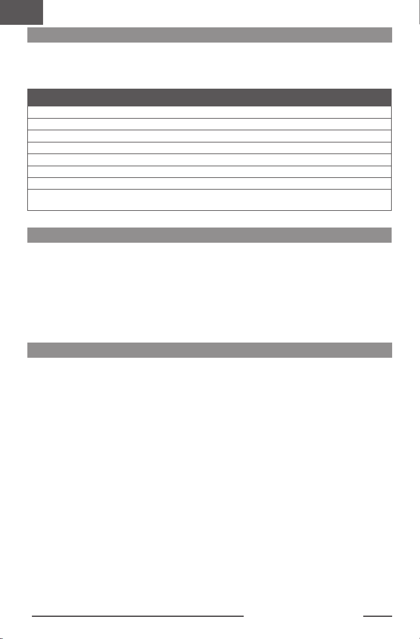
In the binding process, the receiver is programmed to recognize the GUID (Globally Unique Identification) code of a specific transmitter. You must “bind” your chosen aircraft transmitter using Spektrum DSM2/DSMX technology to the receiver
for proper operation.
Any Spektrum DSM2/DSMX transmitter can be bound to a DSM2/DSMX receiver.
Binding Procedure
1. Refer to your transmitter’s manual for binding it to a receiver (location of transmitter’s bind function).
2. Make sure the flight battery is disconnected from the aircraft.
3. Power off your transmitter.
4. Place the aircraft on a level surface away from wind.
5. Connect the flight battery in the aircraft. The receiver LED will begin to flash rapidly (typically after 5 seconds).
6. Make sure the transmitter controls are neutral and the throttle and throttle trim are in low position.
7. Put your transmitter into bind mode. Refer to your transmitter’s manual for binding button or switch instructions.
8. After 5 to 10 seconds, the receiver status LED will turn solid, indicating that the receiver is bound to the transmitter.
If the LED does not turn solid, refer to the Troubleshooting Guide at the back of the manual.
For subsequent flights, power on the transmitter for 5 seconds before connecting the flight battery.
Smart Technology Telemetry
This aircraft includes Spektrum Smart Technology in the
receiver, which can provide telemetry information like battery voltage. To take advantage of Smart Technology, you
will need a compatible transmitter. A firmware update for
your transmitter may be required.
To View Smart Telemetry:
1. Begin with the transmitter bound to the receiver
2. Power on the transmitter.
3. Power on the aircraft.
4. The Smart logo appears under the battery logo on the
home page. A signal bar appears in the top left corner
of the screen.
5. Scroll past the servo monitor to view Smart technology
screens.
For more information about compatible transmitters,
firmware updates, and how to use the Smart Technology
on your transmitter, visit www.SpektrumRC.com.
SAFE® Select Technology
The UMX F-86 Sabre has two flight modes controlled by
Channel 5, SAFE and AS3X. Switch A is the Spektrum
default for Channel 5. Position 0 is SAFE, Position 1 is
AS3X only.
When flying in SAFE mode, the aircraft will return to level
flight any time the aileron and elevator controls are at
neutral. Applying aileron or elevator control will cause the
airplane to bank, climb or dive. The amount the stick is
moved will determine the attitude the airplane flies. Holding full control will push the aircraft to the pre-determined
bank and pitch limits, but it will not go past those angles.
6
When flying in SAFE mode, it is normal to hold the control
stick deflected with moderate aileron input when flying
through a turn. To fly smoothly with SAFE, avoid making
frequent control changes and don’t attempt to correct for
minor deviations. Holding deliberate control inputs will command the aircraft to fly at a specific angle, and the model
will make all corrections to maintain that flight attitude.
Return the elevator and aileron controls to neutral before
switching from SAFE mode to AS3X mode. If you do not
neutralize controls when switching into AS3X mode, the
control inputs used for SAFE mode will be excessive for
AS3X mode and the aircraft will react immediately.
UMX F-86 Sabre 30mm EDF
Page 7
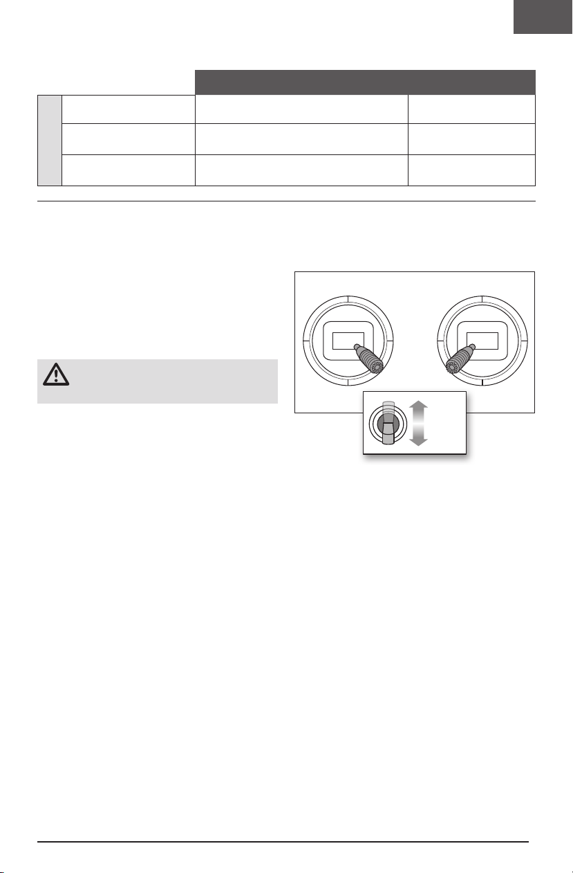
Differences Between SAFE and AS3X Modes
This section is generally accurate but does not take into account flight speed, battery charge status, and other limiting factors.
SAFE Select AS3X
Control stick is neutralized Aircraft will self level
Holding a small amount of
control
Control Input
Holding full control
Aircraft will bank or pitch to a moderate angle
and maintain the attitude
Aircraft will bank or pitch to the predetermined
limits and maintain the attitude
Aircraft will continue to fly at
its present attitude
Aircraft will continue to pitch
or roll slowly
Aircraft will continue to roll or
pitch rapidly
EN
Disabling and Enabling SAFE Select
By default, the SAFE Select function of your UMX aircraft is
enabled and assigned to the Gear channel switch (channel
5). If you do not wish to have access to SAFE Select while
flying, you can choose to disable SAFE Select functionality.
AS3X will still be active when SAFE Select is disabled.
IMPORTANT: Before attempting to disable or enable
SAFE Select, ensure the aileron, elevator, rudder, throttle
and gear channels are all on high rate with the travel
set to 100%. Turn throttle hold OFF if it is programmed
in the transmitter.
CAUTION: Keep all body parts clear of the
propeller, and keep the aircraft securely
restrained in case of accidental throttle activation.
1. Power on the transmitter.
2. Power on the aircraft.
3. Hold both transmitter sticks to the inside bottom
corners and toggle the Gear switch 5 times (1 toggle =
full up and down). The control surfaces of the aircraft
will move, indicating SAFE Select has been enabled
or disabled.
Repeat the process again to re-enable or disable SAFE Select.
DXe, and DXS Transmitters
Switch A is the FMODE switch on the these transmitters,
and the switch needs to be toggled between position 0
and 2 when disabling/enabling SAFE Select.
Mode 1 and 2 Transmitters
100%
x 5
100%
7
Page 8
EN
ESC/Receiver Arming and Battery Installation
CAUTION: Always keep hands away from the
propeller. When armed, the motor will turn the
propeller in response to any throttle movement.
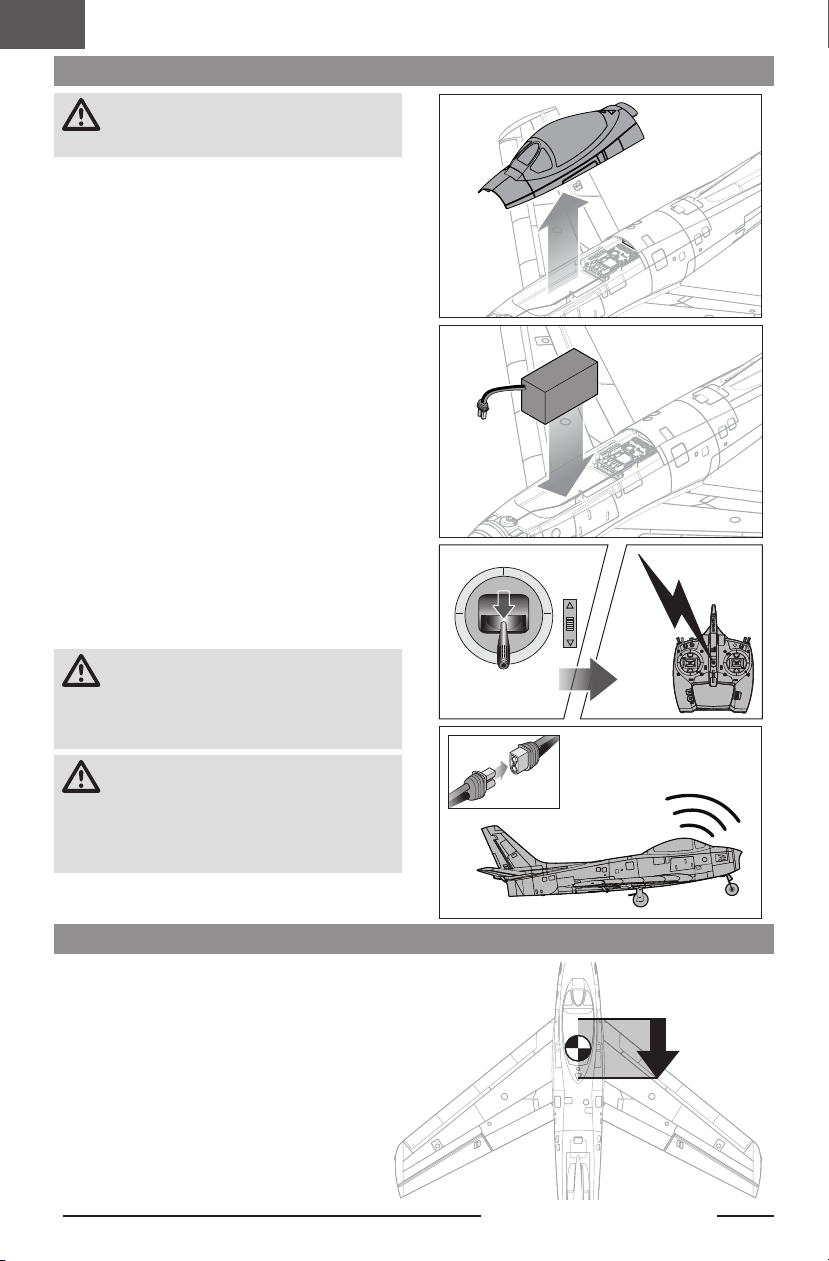
Arming the ESC/receiver also occurs after binding as
previously described, but subsequent connection of a flight
battery requires the following steps.
AS3X
The AS3X® system will not activate until the throttle stick
or trim is increased above 25% for the first time. Once
active, the control surfaces may move rapidly and noisily
on the aircraft. This is normal. AS3X technology will remain
active until the battery is disconnected.
1. Open the battery hatch.
2. Attach the battery to the hook and loop strip so the
battery is centered in the battery cavity.
3. Lower the throttle and power on your transmitter. Enable throttle cut switch.
4. Connect the battery to the ESC, noting proper polarity.
Keep the plane immobile and away from wind for 5
seconds to allow the AS3X system to initialize. A series
of tones and a continuous LED (LED may be difficult
to see as it is located inside of aircraft.) indicates a
successful connection.
A solid blue LED indicates that the aircraft is in SAFE
flight mode and a solid RED LED indicates that the
aircraft is in AS3X flight mode. When the aircraft is in
SAFE the servos will move without increasing throttle
above 25% throttle
CAUTION: Always disconnect the Li-Po battery
from the ESC when not flying to eliminate power
supplied to the motor. The ESC does not have an
arming switch and will respond to any transmitter input
when a signal is present.
CAUTION: Always disconnect the Li-Po battery
from the ESC when not flying to avoid
over-discharging the battery. Batteries discharged to a
voltage lower than the lowest approved voltage may
become damaged, resulting in loss of performance and
potential fire when batteries are charged.
1-2-3-4-5 Sec.
Center of Gravity (CG)
The CG location is 77mm from the leading edge of the
wing, where it meets the fuselage. This CG location has
been determined with the recommended battery. Adjust
the battery forward or aft so the model balances level at
the recommended point.
8
77mm
UMX F-86 Sabre 30mm EDF
Page 9
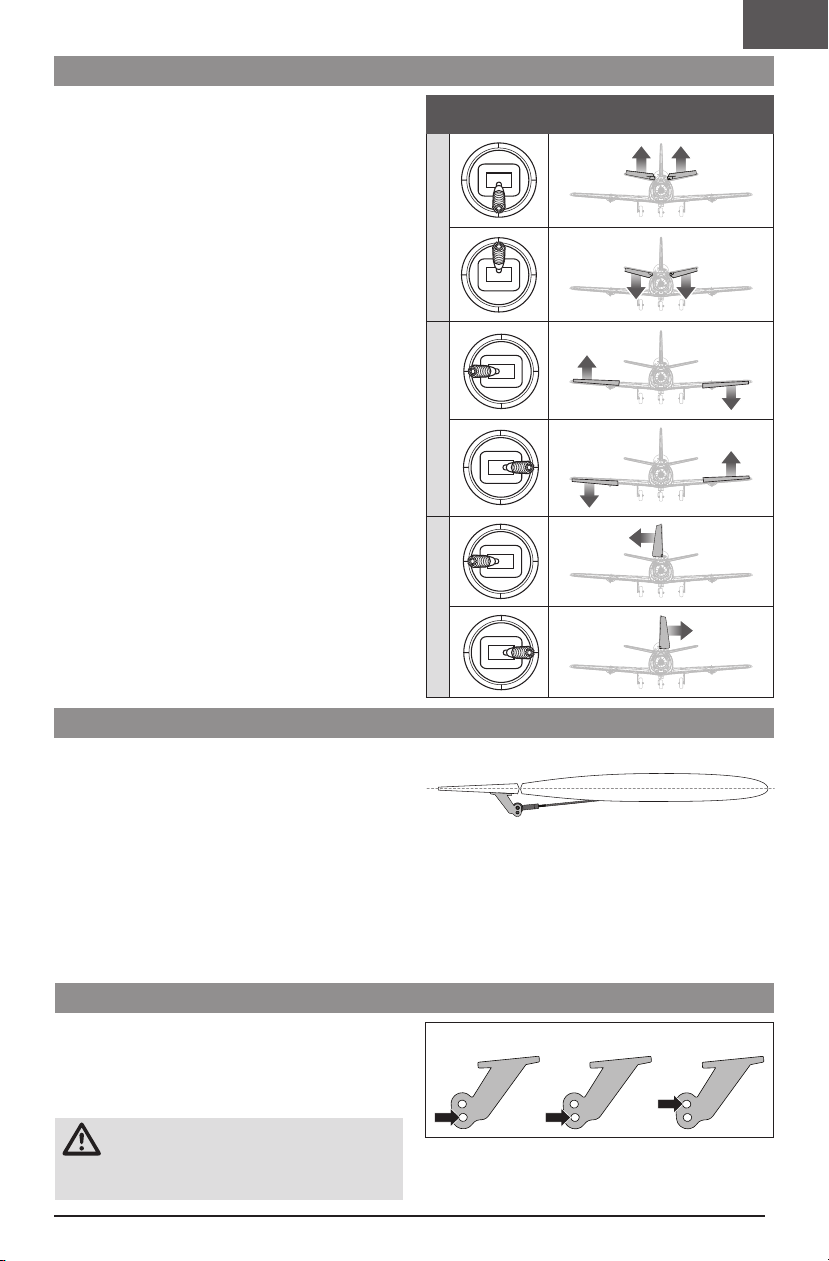
Control Direction Test
Aileron
Elevator
Rudder
Switch on the transmitter, enable throttle cut and connect
the battery. Use the transmitter to operate the aileron,
elevator and rudder controls. View the aircraft from the
rear when checking the control directions.
Elevators
1. Pull the elevator stick back. The elevator should move
up, which will cause the aircraft to pitch up.
2. Push the elevator stick forward. The elevator should
move down, which will cause the aircraft to pitch
down.
Ailerons
3. Move the aileron stick to the left. The left aileron
should move up and the right aileron down, which will
cause the aircraft to bank left.
4. Move the aileron stick to the right. The right aileron
should move up and the left aileron down, which will
cause the aircraft to bank right.
Rudder
5. Move the rudder stick to the left. The rudder should
move to the left, which will cause the aircraft to yaw
left.
6. Move the rudder stick to the right. The rudder should
move to the right, which will cause the aircraft to yaw
right.
Transmitter
Command
ElevatorAileron
EN
Control Surface Response
Control Centering
Before the rst ights, or in the event of an accident,
make sure the ight control surfaces are centered.
Adjust the linkages mechanically if the control surfaces
are not centered. Use of the transmitter sub-trims may not
correctly center the aircraft control surfaces due to the
mechanical limits of linear servos.
1. Make sure the control surfaces are neutral when the
transmitter controls and trims are entered. The transmitter sub-trim must always be set to zero.
2. Remove the ball link connector from the control horn.
3. Adjust the plastic ball link by screwing it in or out, then
reassemble it on the control horn.
Control Horn Settings
The illustration shows the factory settings for the control
horns. Fly the aircraft at factory settings before making
changes.
After flying, you may choose to adjust the linkage positions
for the desired control response.
CAUTION: When these are incorrectly
connected for the pilot’s skill level, unexpected
aircraft response to controls can result. This can cause
damage to the aircraft and personal injury.
Rudder
Centering Controls After First Flights
For best performance with AS3X, it is important that
excessive trim is not used. If the aircraft requires exces-
sive transmitter trim (4 or more clicks of trim per channel),
return the transmitter trim to zero and adjust the linkages
mechanically so that the control surfaces are in the flight
trimmed position.
Aileron Elevator Rudder
9
Page 10
EN
Flying Tips and Repairs
WARNING: Always engage throttle cut before
approaching the aircraft.
Range Check the Radio System
Range check the radio system with the aircraft. Refer to
your specific transmitter instruction manual for range test
information.
Flying
We recommend flying your aircraft outside in no greater
than moderate winds or inside in a large gymnasium. Always avoid flying near houses, trees, wires and buildings.
You should also be careful to avoid flying in areas where
there are many people, such as busy parks, schoolyards
or soccer fields. Consult local laws and ordinances before
choosing a location to fly your aircraft.
Takeoff
Place the aircraft in position for takeoff (facing into the
wind if flying outdoors). Set dual rates to low position and
gradually increase the throttle to ¾ to full and steer with
the rudder. Pull back gently on the elevator and climb to
check trim. Once the trim is adjusted, begin exploring the
flight envelope of the aircraft.
Hand Launching
NOTICE: We recommend hand launching in SAFE Mode,
into the wind at 100% power, in high rates.
When hand launching in SAFE mode, the control unit will
sense the force of the launch and automatically enable
the Hand Launch Assist feature. When this feature is
active, the control unit will add up elevator so the aircraft
climbs at a higher angle for a few seconds. It will return to
standard SAFE mode shortly after launch.
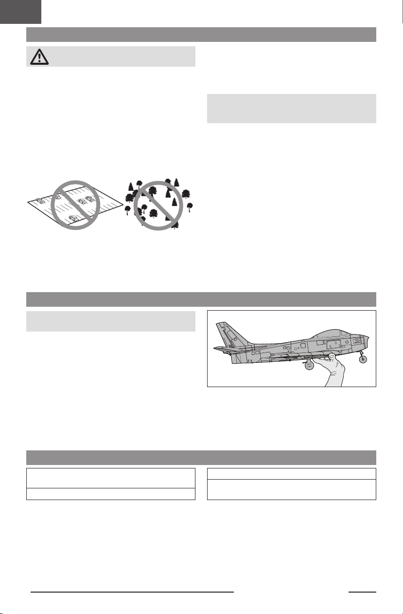
Grip
We recommend holding the aircraft on the bottom of the
fuselage, just behind the wings, as shown.
Landing
Always land into the wind. During the flare, keep the
wings level and the aircraft pointed into the wind. Slowly
lower the throttle while easing back on the elevator to
bring the aircraft gently down on all three wheels.
NOTICE: Always fully lower the throttle at touch down
when landing the aircraft to prevent damage to the
propeller and motor.
Failure to lower the throttle stick and trim to the lowest
possible positions during a crash could result in damage to
the ESC in the receiver unit.
Over-Current Protection (OCP)
The aircraft is equipped with over-current protection. OCP
protects the ESC from overheating and stops the motor
when the transmitter throttle is set too high and the propeller cannot turn. OCP will only activate when the throttle
is positioned just above 1/2 throttle. After the ESC stops
the motor, fully lower the throttle to re-arm the ESC.
Repairs
Crash damage is not covered under warranty.
Repair this aircraft using foam-compatible CA glue or clear
tape. Only use foam-compatible CA glue as other types of
glue can damage the foam. When parts are not repairable,
see the Replacement Parts List for ordering by item number.
Follow Through
Use an overhand throw and launch with wings level and
the nose of the model slightly upwards. Follow through
with your hand launch by pointing your fingers at the
airplane after the throw. Avoid an arcing throw which can
pull the nose down at release.
Post Flight Checklist
Disconnect the flight battery from the ESC (Required for
safety and battery life).
Power OFF the transmitter.
10
Remove the flight battery from the aircraft.
Store the flight battery apart from the aircraft and
monitor the battery charge.
UMX F-86 Sabre 30mm EDF
Page 11
Power Components Service
Disassembly
CAUTION: DO NOT handle the propeller
while the flight battery is connected to the ESC.
Personal injury could result.
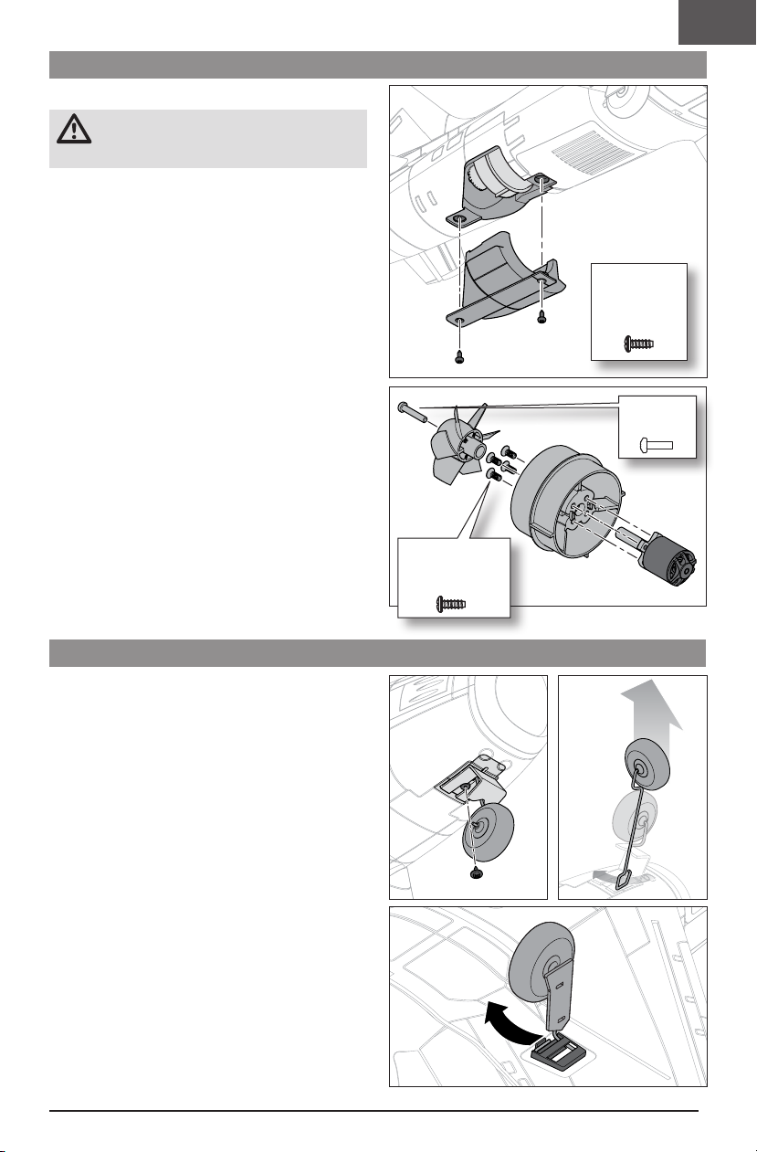
Motor
1. Remove the two M2 x 4mm self-tapping screws using
a Phillips #0 screwdriver from the fan and motor cover.
2. Disconnect the motor wire connector.
3. Remove the motor and fan.
4. Remove the M2 x 8mm screw from the fan using a
Phillips #0 screwdriver.
5. Remove the four M2 x 4mm counter-sunk machine
screws using a Phillips #0 screwdriver.
Assembly
Assemble in reverse order.
• Ensure the propeller adapter and motor mount are fully
connected to the motor.
EN
M2 x 4mm
Phillips Head
Self-Tapping
Screw
M2 x 8mm
Screw
M2 x 4mm
Counter-Sunk
Machine Screw
Landing Gear
The aircraft landing gear comes installed from the factory.
Follow these steps to remove the nose and main landing
gear.
Removing the Nose Landing Gear
1. Remove the M1.2 x 4mm self-tapping screw using a
Phillips #0 screwdriver. The nose gear door will come
off.
2. Pull the nose gear from the fuselage, then rotate the
wheel 90 degrees to remove the wire from the slot.
Removing the Main Landing Gear
3. Use a small flat head screwdriver to gently pry the
wire over the retainer.
4. Pull the landing gear out of the retainer.
11
Page 12
EN
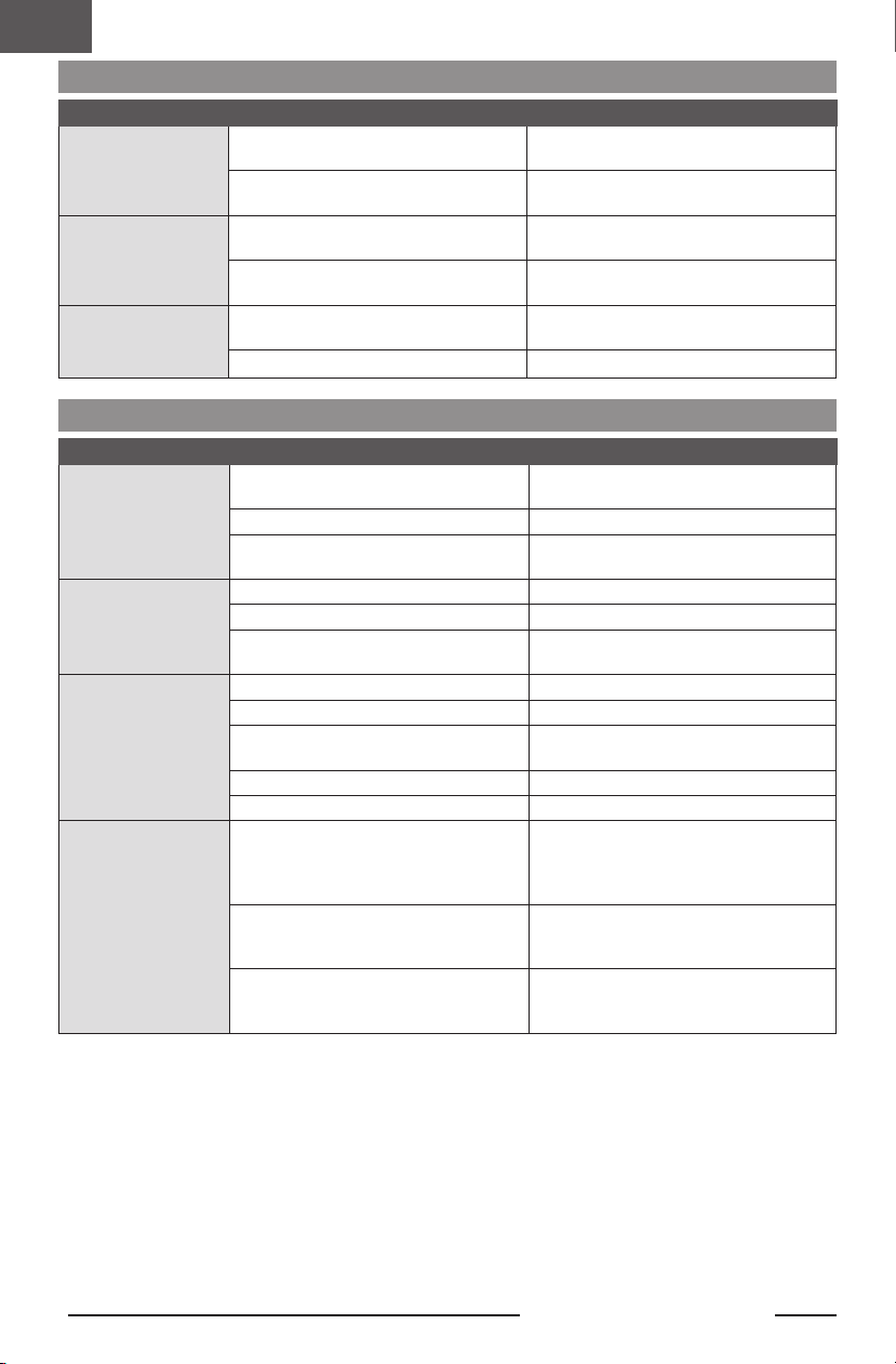
AS3X® System Trouble Shooting Guide
Problem Possible Cause Solution
Control surfaces not at
neutral position when
transmitter controls are
at neutral
Model flies inconsistently
from flight to flight
Controls oscillate in
flight, (model rapidly
jumps or moves)
Control surfaces may not have been
mechanically centered from factory
Aircraft was moved after the flight battery was
connected and before sensors initialized
Aircraft was not kept immobile for 5
seconds after battery was plugged in
Trims are moved too far from neutral position
Propeller is unbalanced, causing excessive
vibration
Propeller screw is loose, causing vibration Tighten the propeller screw
Troubleshooting Guide
Problem Possible Cause Solution
Aircraft will not respond
to throttle but responds
to other controls
Extra propeller noise or
extra vibration
Reduced flight time or
aircraft underpowered
LED on receiver flashes
and aircraft will not bind
to transmitter (during
binding)
Throttle stick and/or throttle trim too high
Throttle channel is reversed Reverse throttle channel on transmitter
Motor disconnected from receiver
Damaged propeller, spinner or motor Replace damaged parts
Propeller screw is loose Tighten the propeller screw
Propeller is out of balance
Flight battery charge is low Completely recharge flight battery
Propeller installed backwards Install propeller with numbers facing forward
Flight battery damaged
Flight conditions may be too cold Make sure battery is warm before use
Battery capacity too low for flight conditions Replace battery or use a larger capacity battery
Transmitter too near aircraft during binding
process
Bind switch or button not held long enough
during bind process
Aircraft or transmitter is too close to large
metal object, wireless source or another
transmitter
Center control surfaces mechanically by
adjusting the U-bends on control linkages
Disconnect and reconnect the flight battery
while keeping the aircraft still for 5 seconds
Keep the aircraft immobile for 5 seconds after
plugging in the battery
Neutralize trims and mechanically adjust
linkages to center control surfaces
Remove propeller and rebalance or replace it if
damaged
Reset controls with throttle stick and throttle
trim at lowest setting
Open fuselage and make sure motor is
connected to the receiver
Remove and balance propeller, or replace with a
balanced propeller
Replace flight battery and follow flight battery
instructions
Power off transmitter, move transmitter a larger
distance from aircraft, disconnect and reconnect flight battery to aircraft and follow binding
instructions
Power off transmitter and repeat bind process.
Hold transmitter bind button or switch until
receiver is bound
Move aircraft and transmitter to another
location and attempt binding again
12
UMX F-86 Sabre 30mm EDF
Page 13
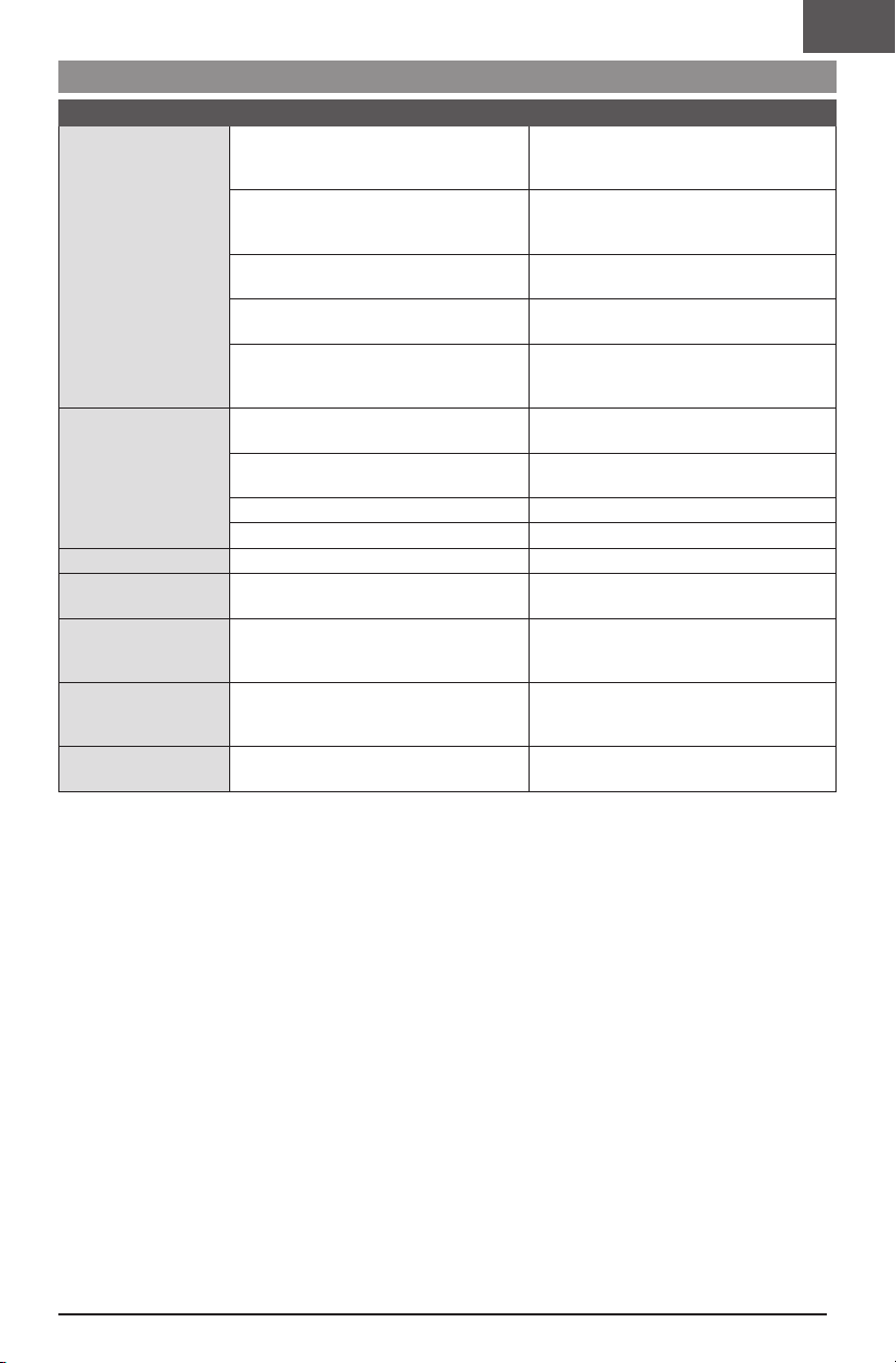
Troubleshooting Guide
Problem Possible Cause Solution
Less than a 5-second wait between first
powering on transmitter and connecting flight
battery to aircraft
Aircraft bound to different model memory
LED on receiver flashes
rapidly and aircraft will
not respond to transmitter (after binding)
Control surface does not
move
Controls reversed Transmitter settings reversed Adjust controls on transmitter appropriately
Motor loses power Damage to motor or power components
Motor power quickly
decreases and increases
then motor loses power
Motor/ESC is not armed
after landing
Servo locks or freezes at
full travel
(ModelMatch™ radios only)
Flight battery/transmitter battery charge is
too low
Transmitter may have been bound to a different model (or with a different DSM Protocol)
Aircraft or transmitter is too close to large
metal object, wireless source or another
transmitter
Control surface, control horn, linkage or
servo damage
Wire damaged or connections loose
Flight battery charge is low Fully recharge flight battery
Control linkage does not move freely Make sure control linkage moves freely
Battery power is down to the point of receiver/
ESC Low Voltage Cutoff (LVC)
Over Current Protection (OCP) stops the
motor when the transmitter throttle is set high
and the propeller cannot turn
Travel adjust value is set above 100%, overdriving the servo
Leaving transmitter on, disconnect and reconnect flight battery to aircraft
Select correct model memory on transmitter
and disconnect and reconnect flight battery to
aircraft
Replace/recharge batteries
Select the right transmitter or bind to the new
one
Move aircraft and transmitter to another
location and attempt linking again
Replace or repair damaged parts and adjust
controls
Do a check of wires and connections, connect
or replace as needed
Do a check of motor and power components for
damage (replace as needed)
Recharge flight battery or replace battery that is
no longer performing
Fully lower throttle and throttle trim to arm ESC
Set travel adjust to 100% or less and/or set subtrims to Zero and adjust linkages mechanically
EN
13
Page 14
EN
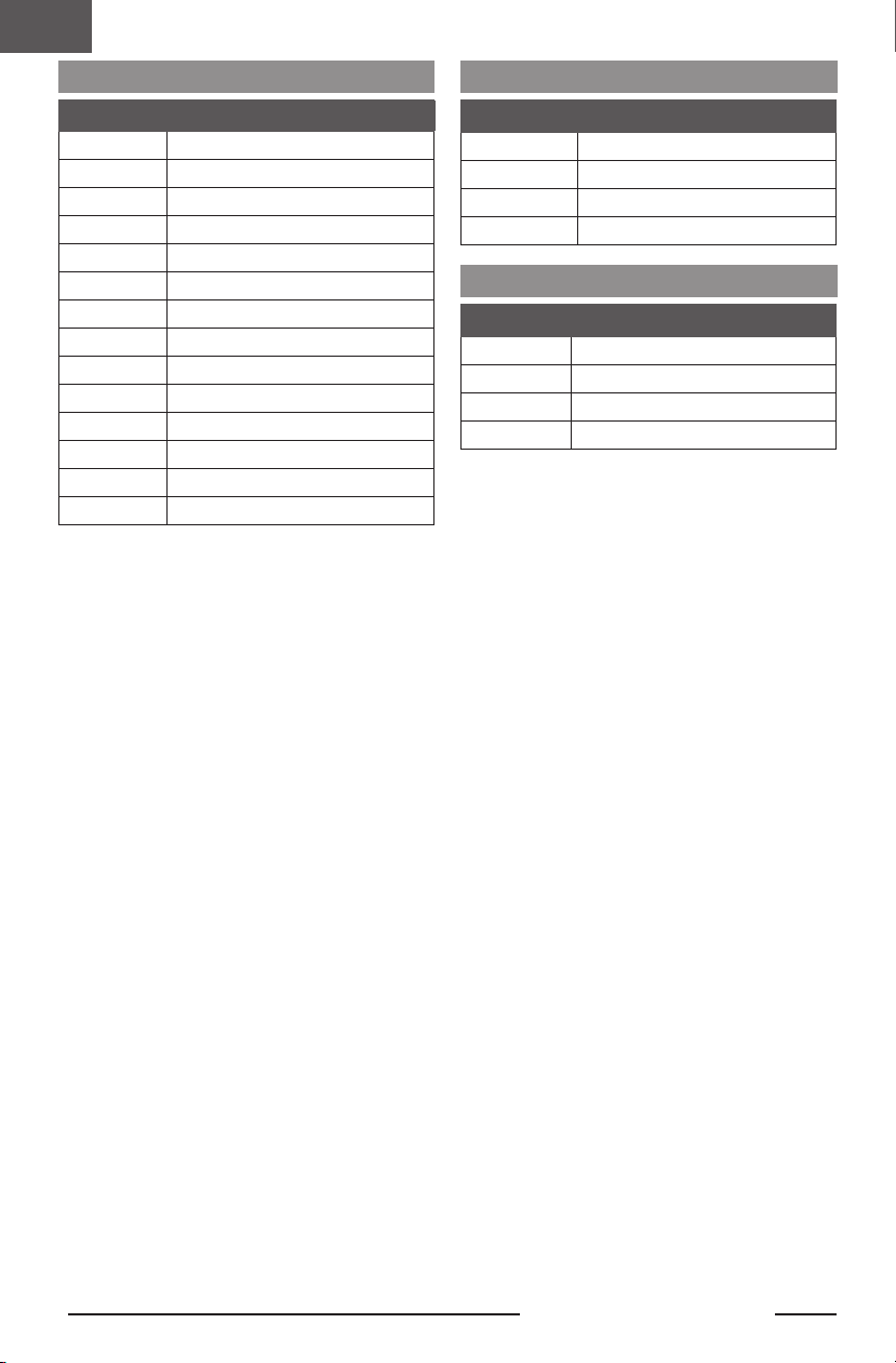
Replacement Parts
Part # Description
EFLU7051 Painted Fuselage: UMX F-86 Sabre
EFLU7052 Tail Set: UMX F-86 Sabre
EFLU7053 Control Horn Set: UMX F-86 Sabre
EFLU7054 Landing Gear Set: UMX F-86 Sabre
EFLU7055 Canopy/Battery Hatch: UMX F-86 Sabre
EFLU7056 Decal Sheet: UMX F-86 Sabre
EFLU7057 Pushrod Set: UMX F-86 Sabre
EFLU7058 Fan Set 30 x 20.5mm
EFLU7059 Fan Rotor 30 x 82mm
EFLU7060 Fan Cover: UMX F-86 Sabre
EFLU7061 Extension Set: UMX F-86 Sabre
SPMA3191 Receiver/ESC Unit: UMX F-86 Sabre
SPMSA201 A201 2.3g Long-Throw Linear Servo
SPMXAM3200 Brushless Motor: 1010-8300Kv
Recommended Parts
Part # Description
SPMR7100 NX7e 7 Channel Transmitter Only
SPMX4504SIC2 14.8V 450mAh 4S 30C LiPo Battery: IC2
SPMXC209 Smart S100 G2 USB-C Charger
SPMXCA320 Adapter: IC3 Battery / IC2 Device
Optional Parts and Accessories
Part # Description
SPMR8200 NX8 8-Channel DSMX Transmitter Only
SPMR10100 NX10 10-Channel DSMX Transmitter Only
SPMXC2060 S250 AC 2x50W Smart Charger
SPMXC2080 S1100 G2 1x100W AC Smart Charger
14
UMX F-86 Sabre 30mm EDF
Page 15
Important Federal Aviation Administration (FAA) Information
Use the QR code below to learn more about the Recreational UAS Safety Test (TRUST), as was introduced by
the 2018 FAA Reauthorization Bill. This free test is required
by the FAA for all recreational flyers in the United States. The
completed certificate must be presented upon request by any
FAA or law enforcement official.
If your model aircraft weighs more than .55lbs or 250 grams,
you are required by the FAA to register as a recreational flyer
and apply your registration number to the outside of your
aircraft. To learn more about registering with the FAA, use the
QR code below.
AMA National Model Aircraft Safety Code
Effective January 1, 2018
A model aircraft is a non-human-carrying device capable of sustained flight within visual line of sight of the pilot or spotter(s). It
may not exceed limitations of this code and is intended exclusively for sport, recreation, education and/or competition. All model
flights must be conducted in accordance with this safety code and related AMA guidelines, any additional rules specific to the
flying site, as well as all applicable laws and regulations.
As an AMA member I agree:
• I will not fly a model aircraft in a careless or reckless
manner.
• I will not interfere with and will yield the right of way to all
human-carrying aircraft using AMA’s See and Avoid Guidance and a spotter when appropriate.
• I will not operate any model aircraft while I am under the
influence of alcohol or any drug that could adversely affect
my ability to safely control the model.
• I will avoid flying directly over unprotected people, moving
vehicles, and occupied structures.
• I will fly Free Flight (FF) and Control Line (CL) models in
compliance with AMA’s safety programming.
• I will maintain visual contact of an RC model aircraft without
enhancement other than corrective lenses prescribed to
me. When using an advanced flight system, such as an
autopilot, or flying First-Person View (FPV), I will comply
with AMA’s Advanced Flight System programming.
• I will only fly models weighing more than 55 pounds,
including fuel, if certified through AMA’s Large Model
Airplane Program.
• I will only fly a turbine-powered model aircraft in compliance with AMA’s Gas Turbine Program.
• I will not fly a powered model outdoors closer than 25 feet
to any individual, except for myself or my helper(s) located
at the flightline, unless I am taking off and landing, or as
otherwise provided in AMA’s Competition Regulation.
• I will use an established safety line to separate all model
aircraft operations from spectators and bystanders.
EN
Limited Warranty
What this Warranty Covers—Horizon Hobby, LLC, (Horizon)
warrants to the original purchaser that the product purchased
(the “Product”) will be free from defects in materials and
workmanship at the date of purchase.
What is Not Covered—This warranty is not transferable and
does not cover (i) cosmetic damage, (ii) damage due to acts of
God, accident, misuse, abuse, negligence, commercial use, or
due to improper use, installation, operation or maintenance, (iii)
modification of or to any part of the Product, (iv) attempted service by anyone other than a Horizon Hobby authorized service
center, (v) Product not purchased from an authorized Horizon
dealer, (vi) Product not compliant with applicable technical
regulations, or (vii) use that violates any applicable laws, rules,
or regulations.
OTHER THAN THE EXPRESS WARRANTY ABOVE, HORIZON
MAKES NO OTHER WARRANTY OR REPRESENTATION, AND
HEREBY DISCLAIMS ANY AND ALL IMPLIED WARRANTIES,
INCLUDING, WITHOUT LIMITATION, THE IMPLIED WARRANTIES
OF NON-INFRINGEMENT, MERCHANTABILITY AND FITNESS
FOR A PARTICULAR PURPOSE. THE PURCHASER ACKNOWLEDGES THAT THEY ALONE HAVE DETERMINED THAT THE
PRODUCT WILL SUITABLY MEET THE REQUIREMENTS OF THE
PURCHASER’S INTENDED USE.
Purchaser’s Remedy—Horizon’s sole obligation and
purchaser’s sole and exclusive remedy shall be that Horizon
will, at its option, either (i) service, or (ii) replace, any Product
determined by Horizon to be defective. Horizon reserves the
right to inspect any and all Product(s) involved in a warranty
claim. Service or replacement decisions are at the sole discretion of Horizon. Proof of purchase is required for all warranty
claims. SERVICE OR REPLACEMENT AS PROVIDED UNDER
THIS WARRANTY IS THE PURCHASER’S SOLE AND EXCLUSIVE
REMEDY.
Limitation of Liability—HORIZON SHALL NOT BE LIABLE
FOR SPECIAL, INDIRECT, INCIDENTAL OR CONSEQUENTIAL
DAMAGES, LOSS OF PROFITS OR PRODUCTION OR COMMERCIAL LOSS IN ANY WAY, REGARDLESS OF WHETHER
SUCH CLAIM IS BASED IN CONTRACT, WARRANTY, TORT,
15
Page 16

EN
NEGLIGENCE, STRICT LIABILITY OR ANY OTHER THEORY OF
LIABILITY, EVEN IF HORIZON HAS BEEN ADVISED OF THE
POSSIBILITY OF SUCH DAMAGES. Further, in no event shall the
liability of Horizon exceed the individual price of the Product on
which liability is asserted. As Horizon has no control over use,
setup, final assembly, modification or misuse, no liability shall
be assumed nor accepted for any resulting damage or injury.
By the act of use, setup or assembly, the user accepts all resulting liability. If you as the purchaser or user are not prepared
to accept the liability associated with the use of the Product,
purchaser is advised to return the Product immediately in new
and unused condition to the place of purchase.
Law—These terms are governed by Illinois law (without
regard to conflict of law principals). This warranty gives you
specific legal rights, and you may also have other rights which
vary from state to state. Horizon reserves the right to change or
modify this warranty at any time without notice.
WARRANTY SERVICES
Questions, Assistance, and Services—Your local hobby
store and/or place of purchase cannot provide warranty support or service. Once assembly, setup or use of the Product
has been started, you must contact your local distributor or
Horizon directly. This will enable Horizon to better answer your
questions and service you in the event that you may need
any assistance. For questions or assistance, please visit our
website at www.horizonhobby.com, submit a Product Support
Inquiry, or call the toll free telephone number referenced in the
Warranty and Service Contact Information section to speak
with a Product Support representative.
Inspection or Services—If this Product needs to be
inspected or serviced and is compliant in the country you live
and use the Product in, please use the Horizon Online Service
Request submission process found on our website or call
Horizon to obtain a Return Merchandise Authorization (RMA)
number. Pack the Product securely using a shipping carton.
Please note that original boxes may be included, but are not
designed to withstand the rigors of shipping without additional
protection. Ship via a carrier that provides tracking and insurance for lost or damaged parcels, as Horizon is not responsible
for merchandise until it arrives and is accepted at our facility.
An Online Service Request is available at http://www.horizonhobby.com/content/service-center_render-service-center. If
you do not have internet access, please contact Horizon Product Support to obtain a RMA number along with instructions for
submitting your product for service. When calling Horizon, you
will be asked to provide your complete name, street address,
email address and phone number where you can be reached
during business hours. When sending product into Horizon,
please include your RMA number, a list of the included items,
and a brief summary of the problem. A copy of your original
sales receipt must be included for warranty consideration. Be
sure your name, address, and RMA number are clearly written
on the outside of the shipping carton.
NOTICE: Do not ship LiPo batteries to Horizon. If you have
any issue with a LiPo battery, please contact the appropriate
Horizon Product Support office.
Warranty Requirements—For Warranty consideration, you
must include your original sales receipt verifying the proofof-purchase date. Provided warranty conditions have been
met, your Product will be serviced or replaced free of charge.
Service or replacement decisions are at the sole discretion of
Horizon.
Non-Warranty Service—Should your service not be covered
by warranty, service will be completed and payment will be
required without notification or estimate of the expense unless
the expense exceeds 50% of the retail purchase cost. By
submitting the item for service you are agreeing to payment of
the service without notification. Service estimates are available
upon request. You must include this request with your item
submitted for service. Non-warranty service estimates will
be billed a minimum of ½ hour of labor. In addition you will
be billed for return freight. Horizon accepts money orders
and cashier’s checks, as well as Visa, MasterCard, American
Express, and Discover cards. By submitting any item to Horizon
for service, you are agreeing to Horizon’s Terms and Conditions
found on our website http://www.horizonhobby.com/content/
service-center_render-service-center.
ATTENTION: Horizon service is limited to Product compli-
ant in the country of use and ownership. If received, a
non-compliant Product will not be serviced. Further, the
sender will be responsible for arranging return shipment of
the un-serviced Product, through a carrier of the sender’s
choice and at the sender’s expense. Horizon will hold noncompliant Product for a period of 60days from notification,
after which it will be discarded.
10/15
Contact Information
Country of
Purchase
(Repairs and Repair Requests)
United States
of America
European Union
16
(Product Technical Assistance)
Horizon Hobby Contact Information Address
Horizon Service Center
Horizon Product Support
Sales
servicecenter.horizonhobby.com/Request-
Form/
877-504-0233
800-338-4639
2904 Research Rd
Champaign, Illinois, 61822 USA
D 22885 Barsbüttel, Germany
UMX F-86 Sabre 30mm EDF
Hanskampring 9
Page 17
FCC Information
Contains FCC ID: BRWWACO1T
This equipment complies with FCC and IC radiation
exposure limits set forth for an uncontrolled environment.
This equipment should be installed and operated with minimum distance 20cm between the radiator and/or antenna
and your body (excluding fingers, hands, wrists, ankles and
feet). This transmitter must not be co-located or operating in
conjunction with any other antenna or transmitter.
Supplier’s Declaration of Conformity
EFL UMX F-86 Sabre 30mm EDF BNF Basic (EFLU7050):
This device complies with part 15 of the FCC Rules. Operation is subject to the following two conditions: (1) This device
may not cause harmful interference, and (2) this device must
accept any interference received, including interference that
may cause undesired operation.
CAUTION: Changes or modifications not expressly
approved by the party responsible for compliance
could void the user’s authority to operate the equipment.
NOTE: This equipment has been tested and found to comply
with the limits for a Class B digital device, pursuant to part
15 of the FCC Rules. These limits are designed to provide
reasonable protection against harmful interference in a
IC Information
CAN ICES-3 (B)/NMB-3(B)
Contains IC: 6157A-WACO1T
This device contains license-exempt transmitter(s)/
receivers(s) that comply with Innovation, Science, and
Economic Development Canada’s license-exempt RSS(s).
Operation is subject to the following 2 conditions:
EN
residential installation. This equipment generates, uses and
can radiate radio frequency energy and, if not installed and
used in accordance with the instructions, may cause harmful
interference to radio communications. However, there is no
guarantee that interference will not occur in a particular installation. If this equipment does cause harmful interference
to radio or television reception, which can be determined by
turning the equipment off and on, the user is encouraged to
try to correct the interference by one or more of the following
measures:
• Reorient or relocate the receiving antenna.
• Increase the separation between the equipment and
receiver.
• Connect the equipment into an outlet on a circuit different
from that to which the receiver is connected.
• Consult the dealer or an experienced radio/TV technician
for help.
Horizon Hobby, LLC
2904 Research Rd.
Champaign, IL 61822
Email: [email protected]
Web: HorizonHobby.com
1. This device may not cause interference.
2. This device must accept any interference, including
interference that may cause undesired operation of the
device.
Compliance Information for the European Union
EU Compliance Statement:
EFL UMX F-86 Sabre 30mm EDF BNF Basic
(EFLU7050): Hereby, Horizon Hobby, LLC
declares that the device is in compliance with the following:
EU Radio Equipment Directive 2014/53/EU, RoHS 2 Directive
2011/65/EU, RoHS 3 Directive - Amending 2011/65/EU
Annex II 2015/863.
The full text of the EU declaration of conformity is available
at the following internet address: https://www.horizonhobby.
com/content/support-render-compliance.
Receiver:
2402–2478 MHz
1.43dBm
EU Manufacturer of Record:
Horizon Hobby, LLC
2904 Research Road
Champaign, IL 61822 USA
EU Importer of Record:
Horizon Hobby, GmbH
Hanskampring 9
22885 Barsbüttel Germany
WEEE NOTICE:
facility to enable recovery and recycling.
This appliance is labeled in accordance with
European Directive 2012/19/EU concerning
waste of electrical and electronic equipment
(WEEE). This label indicates that this product
should not be disposed of with household
waste. It should be deposited at an appropriate
17
Page 18

E-flite, Bind-N-Fly, BNF, the BNF logo, DSM, DSM2, DSMX, Spektrum AirWare, EC3, IC3, AS3X, SAFE, the SAFE logo,
ModelMatch, and the Horizon Hobby logo are trademarks or registered trademarks of Horizon Hobby, LLC.
The Spektrum trademark is used with permission of Bachmann Industries, Inc.
All other trademarks, service marks and logos are property of their respective owners.
US 8,672,726 US 9,056,667 US 9,753,457. US 10,078,329. US 9,930,567. US 10,419,970. Other patents pending.
Created 12/23 67213 EFLU7050
©2023 Horizon Hobby, LLC.
http://www.horizonhobby.com/
UMX F-86 Sabre 30mm EDF
 Loading...