

Page 1
Instruction Manual
Bedienungsanleitung
Manuel d’utilisation
Manuale di Istruzioni
™
Page 2
EN
NOTICE
All instructions, warranties and other collateral documents are subject to change at the sole discretion of
Horizon Hobby, Inc. For up-to-date product literature, visit horizonhobby.com and click on the support tab for this
product.
Meaning of Special Language
The following terms are used throughout the product literature to indicate various levels of potential harm when
operating this product:
NOTICE: Procedures, which if not properly followed, create a possibility of physical property damage AND a little
or no possibility of injury.
CAUTION: Procedures, which if not properly followed, create the probability of physical property damage AND a
possibility of serious injury.
WARNING: Procedures, which if not properly followed, create the probability of property damage, collateral
damage, and serious injury OR create a high probability of superficial injury.
WARNING: Read the ENTIRE instruction manual to become familiar with the features of the
product before operating. Failure to operate the product correctly can result in damage to the
product, personal property and cause serious injury.
This is a sophisticated hobby product. It must be operated with caution and common sense and
requires some basic mechanical ability. Failure to operate this Product in a safe and responsible manner could result in injury or damage to the product or other property. This product is not intended for
use by children without direct adult supervision. Do not attempt disassembly, use with incompatible
components or augment product in any way without the approval of Horizon Hobby, Inc. This manual
contains instructions for safety, operation and maintenance. It is essential to read and follow all the
instructions and warnings in the manual, prior to assembly, setup or use, in order to operate correctly
and avoid damage or serious injury.
Additional Safety Precautions and Warnings
Age Recommendation: Not for children under 14 years. This is not a toy.
As the user of this product, you are solely responsible for operating it in a manner that does not
endanger yourself and others or result in damage to the product or the property of others.
This model is controlled by a radio signal that is subject to interference from many sources outside
your control. This interference can cause momentary loss of control so it is advisable to always keep a
safe distance in all directions around your model, as this margin will help to avoid collisions or injury.
Never operate your model with low transmitter batteries.
Always operate your model in open spaces away from full-size vehicles, traffic and people.
Carefully follow the directions and warnings for this and any optional support equipment (chargers,
rechargeable battery packs, etc.).
Keep all chemicals, small parts and anything electrical out of the reach of children.
Moisture causes damage to electronics. Avoid water exposure to all equipment not specifically designed and protected for this purpose.
Never lick or place any portion of your model in your mouth as it could cause serious injury or even
death.
2
Page 3
Introduction
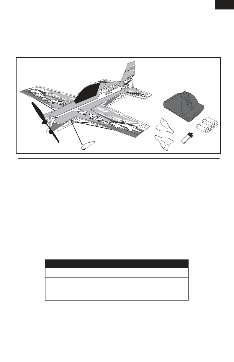
Designed for 3D aerobatics even in relatively small indoor spaces, the UMX Extra 300 3D utilizes
micro light film over laser cut foam with carbon reinforcement to create an ultra lightweight aerobatic
performer. Designed by ETOC Champion Seth Arnold, the UMX Extra 300 3D has been totally optimized
to deliver extreme 3D performance for any experienced pilot. Charge the flight battery, dial in the proper
setup to your transmitter, bind to the model and fly all-out 3D almost anywhere.
Table of Contents
EN
Additional Safety Precautions and Warnings ..2
Battery Warnings ........................................4
Charging the Battery ...................................5
Transmitter and Receiver Binding .................6
Before Flight ...............................................6
First Flight Preparation ................................6
Control Direction Test ..................................7
Control Centering ........................................ 7
Settings for Control Horns ............................7
Adjusting Center of Gravity (CG) ...................7
Dual Rates and Expo ...................................8
UMX Extra 300 3D Specifications
Wingspan
Length
Weight
To register your product online, go to www.e-fliterc.com
Flying Tips and Repairs ................................8
Maintenance After Flying .............................8
Installation of Side Force Generator (SFG) .....9
Service of Power Components .....................9
Replacement Parts ....................................10
Optional Parts ........................................... 10
Troubleshooting Guide ...............................11
Warranty and Repair Policy ........................ 12
Contact Information ...................................13
Declaration of Conformity ..........................13
16.8 in (427mm)
19.4 in (494mm)
0.98 oz (28 g) without battery
1.2 oz (32.5 g) with battery
3
Page 4
EN
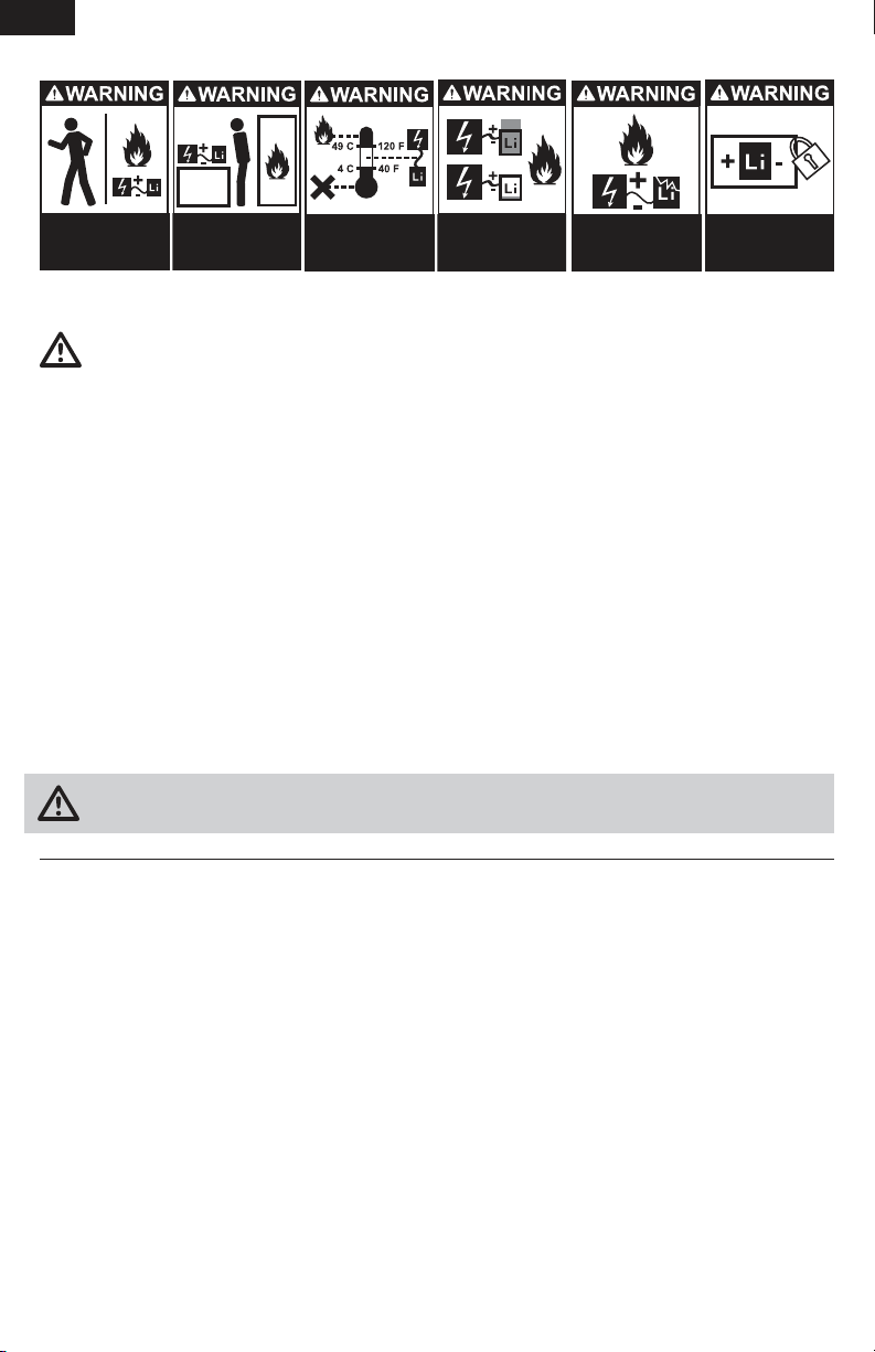
Never leave
charging Batteries
unattended.
Always charge
Batteries away from
flammable materials.
Never charge
Batteries outside safe
temperature range.
Never charge
Batteries outside
recommended levels.
Store
Batteries
safely.
Never charge
damaged Batteries.
Battery Warnings
The Battery Charger (EFLC1003) included with the UMX Extra 300 3D has been designed to safely charge
the Li-Po battery.
CAUTION: All instructions and warnings must be followed exactly. Mishandling of Li-Po batteries can
result in a fire, personal injury, and/or property damage.
•Byhandling,chargingorusingtheincludedLi-Pobatteryyouassumeallrisksassociatedwithlithium
batteries. If you do not agree with these conditions, return your complete UMX Extra 300 3D model in
new, unused condition to the place of purchase immediately.
•DONOTUSEANi-CdORNi-MHCHARGER.Failuretochargethebatterywithacompatiblechargermay
cause fire resulting in personal injury and/or property damage.
•Ifatanytimethebatterybeginstoballoonorswell,discontinueuseimmediately.Ifchargingordischarg-
ing, discontinue and disconnect. Continuing to use, charge or discharge a battery that is ballooning or
swelling can result in fire.
•Storethebatteryatroomtemperatureinadryareaforbestresults.
•Whentransportingortemporarilystoringthebatterythetemperaturerangeshouldbefrom40–120ºF.Do
not store battery or model in a car or direct sunlight. If stored in a hot car, the battery can be damaged or
even catch fire.
•Li-Pocellsshouldnotbedischargedtobelow3Veachunderload.
•Donotcoverwarninglabelswithhookandloopstrips.
WARNING:OnlyuseanE-ite6Vpowersupplywiththischarger.DONOTusea12Vpowersupplyor
property damage and injury could occur.
Low Voltage Cutoff (LVC)
WhenaLi-Pobatteryisdischargedbelow3Vpercell,itwillnotholdacharge.TheUMXExtra3003DESC
protectstheightbatteryfromover-dischargeusingLowVoltageCutoff(LVC).Beforethebatterychargede-
creasestoomuch,LVCremovespowersupplyfromthemotor.Powertothemotordecreasesandincreases,
showing some battery power is reserved for flight control and safe landing.
When the motor power decreases then increases, please land the aircraft immediately and recharge the
flight battery.
Disconnect and remove the Li-Po battery from the aircraft after use to prevent trickle discharge. Before
storage, charge the Li-Po battery to full capacity. During storage make sure battery charge does not go
below3Vpercell.
NOTICE:RepeatedyingtoLVCwilldamagethebattery.
4
Page 5
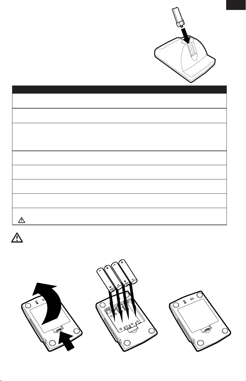
Charging the Battery
YourUMXExtra3003Dcomeswitha1S3.7VLi-PoBattery
Chargerand150mAh1-Cell3.7V12CLi-Pobattery.Itis
important that you only charge with the included charger,
or the E-flite® Celectra™ 4-port Charger (EFLC1004). Refer
to battery warnings. We recommend you charge the battery
pack first. You will need the flight battery to confirm proper
aircraft operation in future steps.
The Battery Charging Process
1. Charge only batteries that are cool to the touch and are not damaged. Look at the battery to make
sure it is not damaged e.g., swollen, bent, broken or punctured.
2. Remove the cover on the bottom of the charger and install four of the included AA batteries, noting
proper polarity. Replace the cover after the AA batteries are installed.
3. Slide the battery into the slot on the charger. The end cap of the battery is specifically designed to
allow the battery to fit into the slot one way (usually with the label on the battery facing outward)
to prevent reverse polarity connection. However, check for proper alignment and polarity before
proceeding to the next step.
4.Gentlypressthebatteryanditsconnectorintothechargejack/connectorlocatedatthebottomof
the slot in the charger.
5. When you make the connection successfully, the LED on the charger turns solid red, indicating
charging has begun.
6.Chargingafullydischarged(notover-discharged)150mAhbatterytakesapproximately25–30
minutes. As the battery nears full charge, the LED begins to blink.
7. When the battery is fully charged, the LED blinks approximately every 20 seconds or goes out entirely. Note: If the LED stays on when the Li-Po is removed, the AA batteries in the charger are low.
8. Always unplug the battery from the charger immediately upon completion of charging.
CAUTION: Overcharging a battery can cause a fire.
EN
WARNING: Failure to use the proper charger for a Li-Po battery can result in serious damage, and if
left charging long enough, will cause a fire. ALWAYS use caution when charging Li-Po batteries.
5
Page 6
EN
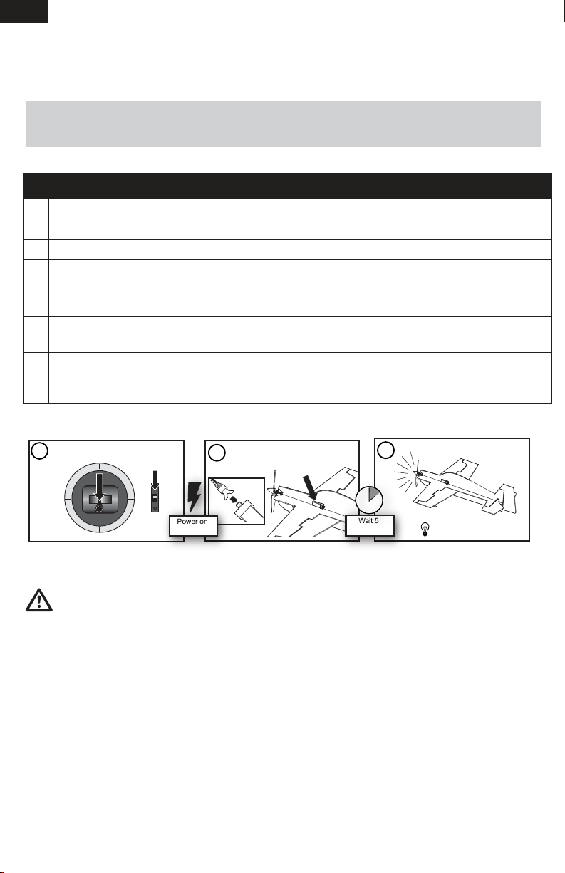
1
Lower throttle and throttle trim
to lowest settings.
2
3
Continuous LED
Power on
transmitter
Wait 5
seconds
Connect Flight Battery and attach
to hook and loop strip.
Transmitter and Receiver Binding
BindingistheprocessofprogrammingthereceiverofthecontrolunittorecognizetheGUID(Globally
Unique Identifier) code of a single specific transmitter. You need to ‘bind’ your chosen Spektrum DSM2
technology equipped aircraft transmitter to the receiver for proper operation.
Note: Any JR® or Spektrum DSM2 aircraft transmitter can bind to the Spektrum AR6400L receiver. Due to the
aerobatic capabilities of the UMX Extra 300 3D, we recommend using a transmitter with adjustable exponential
and dual rates. Please visit www.bindnfly.com for a complete list of compatible transmitters.
Note: When using a Futaba transmitter with a Spektrum DSM2 module, you will need to reverse the throttle channel.
Binding Procedure
1. Refer to your transmitter’s unique instructions for binding to a receiver.
2. Make sure the flight battery is disconnected from the aircraft.
3. Power off your transmitter.
4. Connect the flight battery in the aircraft. The receiver LED will begin to flash rapidly (typically after 5
seconds).
5. Make sure transmitter controls are neutral and throttle and throttle trim are in low position.
6. Put your transmitter into bind mode. Refer to your transmitter’s manual for binding button or switch
instructions.
7. After 5 to 10 seconds, the receiver status LED will become solid, indicating the receiver is bound to
the transmitter.
Note:IftheLEDdoesnotgotoasolidlight,refertoTroubleshootingGuideatbackofmanual.
Before Flight
Note: Always disconnect the Li-Po from the receiver of the aircraft when not flying. Failure to do so will
render the battery unusable.
CAUTION: When armed, the motor will turn the propeller in response to any throttle movement.
When the aircraft does not respond, binding may be required.
First Flight Preparation
•Removeandinspectcontents
•Readthisinstructionmanualthoroughly
•Bindaircrafttoyourtransmitter
•Installtheightbatteryintheaircraft
(once it has been fully charged)
•Makesurecarbonbercontrolrodsmovefreely
•Makesureightcontrolsurfacesarecentered
6
•PerformtheControlDirectionTestwiththe
transmitter
•Adjustightcontrolsandtransmitter
•Adjustbatteryforcenterofgravity(CG)
•PerformaradiosystemRangeCheck
•Findasafeandopenarea
•Planightforyingconditions
Page 7
Control Direction Test
You should bind your aircraft and transmitter before doing these tests. Move the controls on the transmitter
to make sure aircraft control surfaces move correctly and in the proper direction.
Control Centering
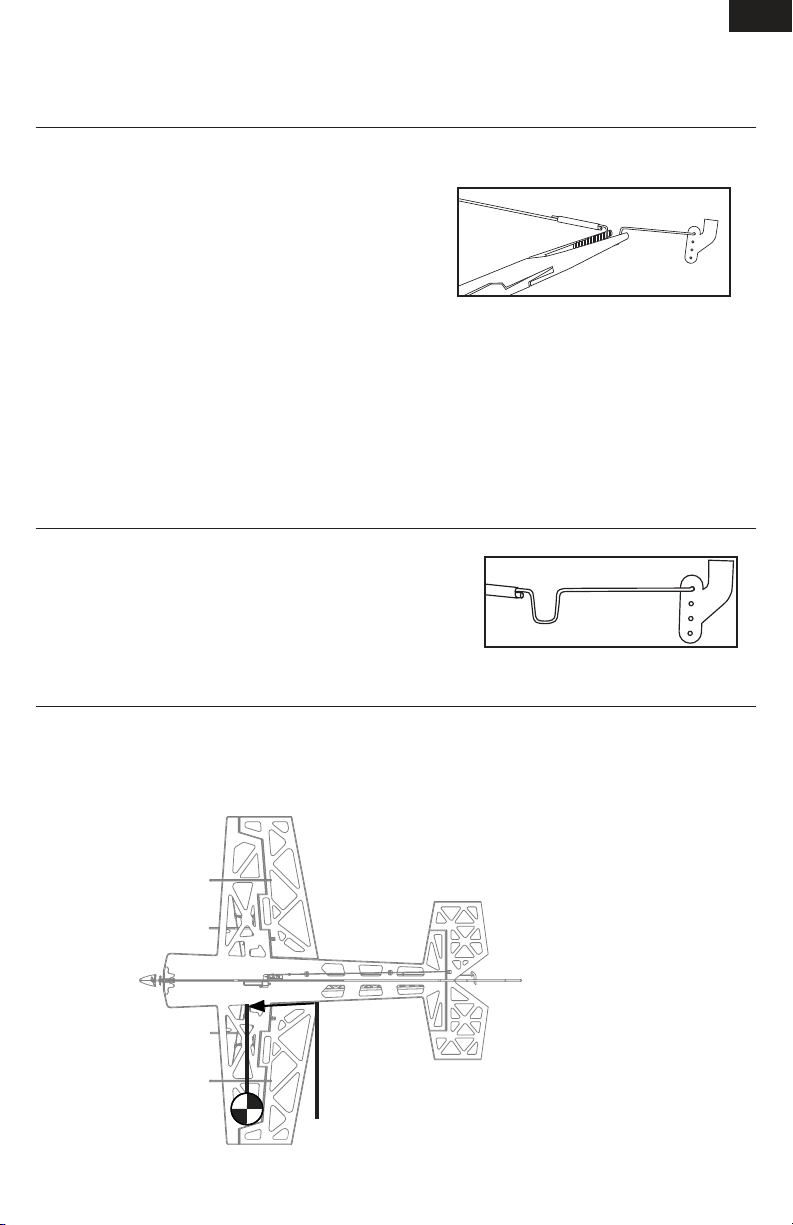
Before first flights, or in the event of an accident, make sure
the flight control surfaces are centered. Adjust pushrods
mechanically. Adjustment only in the transmitter may not
correctly adjust aircraft control surfaces due to mechanical
limits of linear servos.
1. Make sure transmitter trims are neutral and control surfaces are centered. Where possible, transmitter sub-trim must be set to 0.
2. When needed, use a pair of pliers to carefully bend the metal of the pushrod (see illustration).
3. Make the U-shape narrower to make the pushrod shorter. Make the U-shape wider to make the
pushrod longer.
Note: Do not use Sub-Trim to adjust the center position of the servo, and never set Travel adjust values
above 100%. Ultra Micro servos are unique in that they are calibrated to reach maximum travel at 100%.
Increasing the value above 100% will NOT result in more travel, but can cause the servo to lock and will
result in poor flight characteristics.
Settings for Control Horns
The picture here shows positions chosen for the most balanced
aerobatic response. Changing this configuration dramatically
affects aircraft response. Picture not to scale.
Elevator, Aileron and Rudder
Attachment
EN
Adjusting Center of Gravity (CG)
TheCGlocationis82mmforwardfromthetrailingedgeoftheaileronatthefuselage.
Note:AdjustCGbymovingightbatteryonfuselage.
82mm
7
Page 8
EN
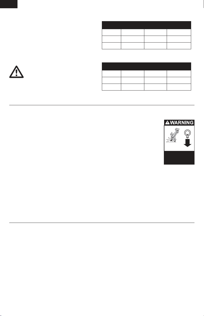
Always
decrease throttle at
propeller strike.
Dual Rates and Expo
We recommend using a DSM2 radio capable of
dual rates and expo. Adjust according to individual
preferences after initial flight. The DX5e transmitter
is not recommended.
NOTICE: DONOTSETYOURTRANSMITTERATV
OVER100%.IftheATVissetover100%itwill
not result in more control movement, and it will
overdrive the servo and cause damage.
CAUTION: Pushrod connections on control
horns directly affect aircraft response.
When these are incorrectly connected for
the pilot’s skill level, unexpected aircraft response
to controls can result. This can cause damage to
the aircraft and personal injury.
Flying Tips and Repairs
Flying
For the initial flights the UMX Extra 300 3D should
be flown in a gymnasium or large open space.
If flown outdoors, fly only in an open yard or
drivewayandinVERYlowwinds.Youshouldalso
be careful to avoid flying in areas where there are
many people, such as busy parks, schoolyards, or
soccer fields. Consult local laws and ordinances
before choosing a location to fly your aircraft.
Set all control surfaces at low rate. Place the UMX
Extra 300 3D in position for takeoff (facing into the
wind,ifoutdoors).Graduallyincreasethethrottleto
¾ to full, and steer with the rudder. Pull back gently
with the elevator and climb to check trim. Once the
trim is adjusted, begin exploring the flight envelope
of the UMX Extra 300 3D.
Dual Rates
Low High 3D
Aileron 50% 65% 100%
Elevator 40% 55% 100%
Rudder 50% 70% 100%
Expo
Low High 3D
Aileron 25% 40% 50%
Elevator 15% 25% 45%
Rudder 20% 35% 45%
Note: Always fully lower the
throttle when the aircraft lands
to prevent damage to the ESC.
Note: Crash damage is not
covered under warranty.
Heat, direct sunlight or crash
damage can wrinkle the film
covering on the aircraft. This
will not decrease aircraft
performance.
Repairs
Thanks to the construction of the UMX Extra 300
3D, repairs to the foam can be made using foamsafe CA or tape. When parts are not repairable, see
the Replacement Parts List for ordering by item
number.
Maintenance After Flying
•DisconnectightbatteryfromESC
(Required for Safety)
•Powerofftransmitter
•Removeightbatteryfromaircraft
•Rechargeightbattery
For current product information, go to www.e-fliterc.com
8
•Repairorreplacealldamagedparts
•Storeightbatteryapartfromaircraftandmonitor
the battery charge
•Makenoteofightconditionsandightplan
results, planning for future flights
Page 9
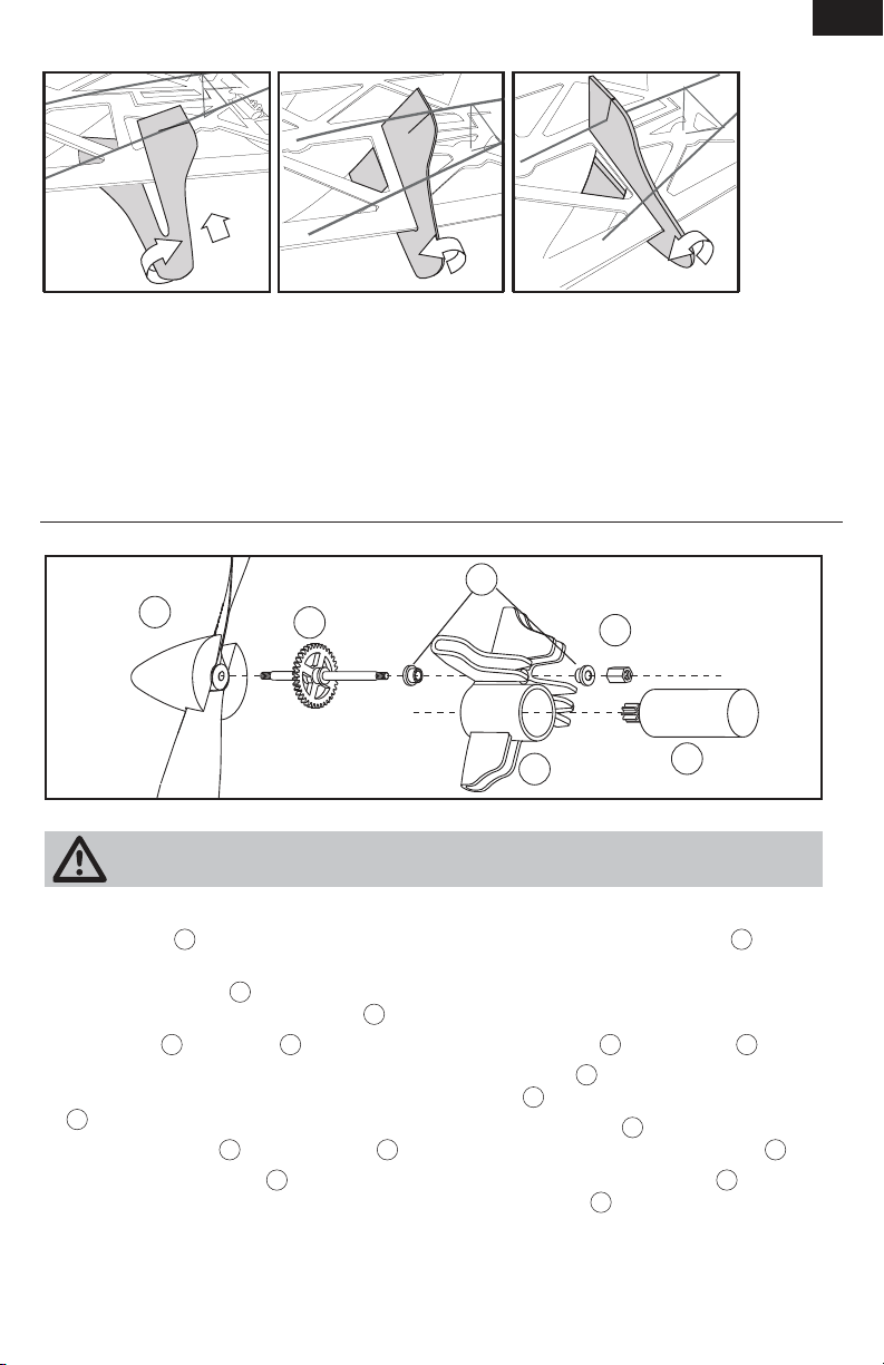
Installation of Side Force Generator (SFG)
EN
SFGshelpwithknife-edgeying.Theyaddside
force in all attitudes which greatly increases rudder
authority making a variety of 3D aerobatics possible. However, installation is optional.
1.TurnSFGsoitisnearatinrelationtothewing.
2.LowerpartofSFGwithpre-cutslotmustgo
under carbon wing supports.
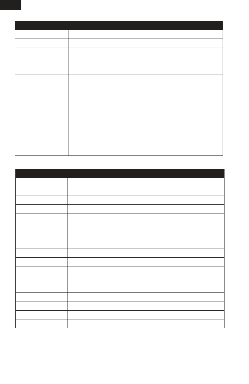
Service of Power Components
A
CAUTION: DO NOT handle propeller parts while the flight battery is connected.
Personal injury could result.
Disassembly
B
•Holdtheshaft
or hemostats.
•Removethepropeller
counterclockwise on the threaded shaft
•Holdthenut
nose pliers or hemostats.
•Turnthespurgearontheshaft
B
clockwise to remove the nut.
•Gentlypulltheshaft
Note: Make sure bushings
gear shaft is removed from the gearbox.
using needle-nose pliers
E
on the shaft B using needle-
B
B
A
by turning it
from the gearbox D.
C
are not lost when
B
3.PutchannelinSFGonwing.
4.TurnSFGcarefullysorearsupportgoesinslotin
SFG(seeillustration).
5.AttachSFGtowingandcarbonsupportsusing
foam-safe CA.
6.AttachanSFGonotherwingusinginstructions
above.
C
E
D
Assembly
•Turna130mmx70mmpropeller
on the shaft.
Note: Numbers on the propeller must face out
from fuselage for correct propeller operation.
•Installtheshaft
•Holdthenut
•Turnthespurgear
Note: Carefully align gear shaft
Note: Avoid disconnecting motor from receiver.
B
shaft
the nut is tightly installed on the shaft
gear on motor
When motor is connected to the receiver, make
sure wire connectors are correctly aligned so
motor turns the propeller in the correct direction.
B
E
on the back of the
.
F
.
F
Note: Wiring not shown
A
clockwise
in the gearbox D.
B
counterclockwise until
B
with pinion
B
.
9
Page 10
EN
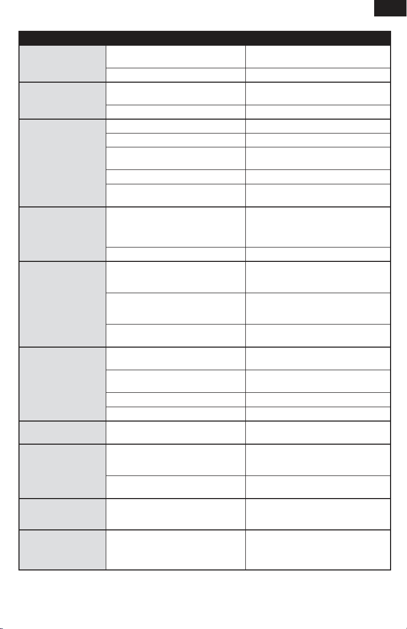
Replacement Parts
Number Description
EFLU1053
EFLU1055
EFLU1056
EFLU1057
EFLU1070
EFL9051
EFL9052
EFL9054
SPM6832
EFLH1067
SPMAS2000L
EFLB1501S
PKZ3052 Battery Connector with Wire
SPMAR6400L AR6400L DSM2 6 Channel Ultra Micro Receiver
GearboxwithPropellerShaft:UMXExtra3003D
LandingGearwithMounts:UMXExtra3003D
Hardware Set: UMX Extra 300 3D
Wing Bracing with Mounts: UMX Extra 300 3D
Replacement Airframe: UMX Extra 300 3D
Propeller with Spinner (2): 130mm x 70mm
Motor: UMX 4Site/Extra 300 3D
PropShaftWithGear(2):UMX4-Site/Extra3003D
Replacement Servo Mechanics: Ultra Micro Long Throw
Replacement Servo Retaining Collars
1.7g-Linear Long Throw Servo
1S3.7V150mAhLi-PoBattery
Optional Parts
Number Description
EFLC1004
EFLC1005 ACto6VDC1.5-AmpPowerSupply(UnitedStates)
EFLC1005AU ACto6VDC1.5-AmpPowerSupply(Australia)
EFLC1005EU ACto6VDC1.5-AmpPowerSupply(Europe)
EFLC1005UK ACto6VDC1.5-AmpPowerSupply(UnitedKingdom)
SPMR6600 DX6i 6-Channel Transmitter Mode 2
SPMR66001 DX6i 6-Channel Transmitter Mode 1
SPMR6600E DX6i 6-Channel Transmitter Mode 2 (Europe)
SPMR66001E DX6i 6-Channel Transmitter Mode 1 (Europe)
SPM66001FR DX6i 6-Channel Full Range Transmitter without servo Mode 1 (France)
SPM6600FR DX6i 6-Channel Full Range Transmitter without servo Mode 2 (France)
SPMR7700 DX7 7-Channel Transmitter Mode 2
SPMR77001 DX7 7-Channel Transmitter Mode 1
SPM8800 DX8 with AR8000 Transmitter/Receiver Only
SPM8800EU DX8 with AR8000 Transmitter/Receiver Only (Europe)
SPM88001AU DX8 with AR8000 Transmitter/Receiver Only Mode 1 (Australia)
SPM88001FR DX8 with AR8000 Transmitter/Receiver Only Mode 1 (France)
To purchase directly from Horizon Hobby, please visit www.horizonhobby.com
or call Horizon’s Consumer Sales Division: (800) 338-4639.
For current product information, go to www.e-fliterc.com.
Celectra4-Port1S3.7V0.3ADCLi-PoCharger
10
Page 11
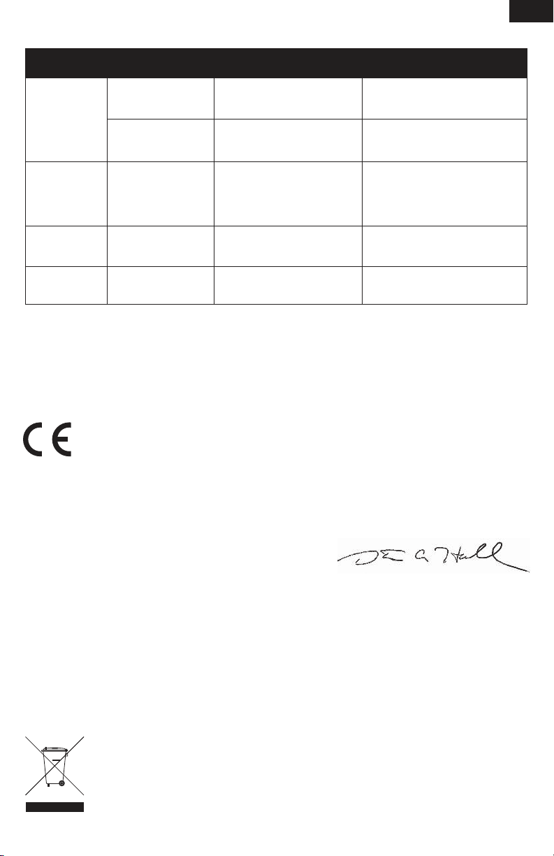
Troubleshooting Guide
Problem Possible Cause Solution
Aircraft will not respond
to throttle but responds to
other controls
Extra propeller noise or
extra vibration
Reduced flight time or
aircraft underpowered
LED on receiver flashes
rapidly and aircraft will
not respond to transmitter (during binding).
LED on receiver flashes
rapidly and aircraft will
not respond to transmitter (after binding).
Control surface does not
move
Controls reversed Transmitter settings reversed Do the Control Direction Test and adjust con-
Motor loses power Damage to motor, propeller shaft or power
Motor power decreases
and increases then
motor loses power
Servo reaches full travel
before transmitter stick is
at maximum deflection.
Throttle not at idle and/or throttle trim
too high
Throttle channel is reversed Reverse throttle channel on transmitter
Damaged propeller and spinner, propeller
shaft or motor
Nut on prop shaft is too loose Tighten the prop shaft nut 1/2 turn
Flight battery charge is low Completely recharge flight battery
Propeller installed backwards Install propeller with numbers facing forward
Flight battery damaged Replace flight battery and follow flight
Flight conditions may be too cold Make sure battery is warm before use
Battery capacity may be low for flight
conditions
Transmitter too near aircraft during binding
process
Aircraft not bound to transmitter Bind transmitter to aircraft receiver
Less than a 5-second wait between first
powering on transmitter and connecting
flight battery to aircraft
Aircraft bound to different model memory
(ModelMatch radios only)
Flight battery/Transmitter battery charge
is too low
Control surface, control horn, linkage or
servo damage
Wire damaged or connections loose Do a check of wires and connections,
Flight battery charge is low Fully recharge flight battery
Carbon fiber control rods stuck on support Free carbon fiber control rods from support
components
Nut on prop shaft is too tight Loosen prop shaft nut until propeller shaft
ReceiverusesdefaultsoftLowVoltage
Cutoff(LVC)
Radio has sub-trim set to value other than
0, or Travel adjust value is set above 100%
Reset controls with throttle stick and throttle
trim at lowest setting
Replace damaged parts
battery instructions
Replace battery or use a larger capacity
battery
Power off transmitter, move transmitter a
larger distance from aircraft, disconnect and
reconnect flight battery to aircraft and follow
binding instructions.
Leaving transmitter on, disconnect and
reconnect flight battery to aircraft
Select correct model memory on transmitter
and disconnect and reconnect flight battery
to aircraft
Replace/recharge batteries
Replace or repair damaged parts and
adjust controls
connect or replace as needed
trols on transmitter appropriately
Do a check of batteries, transmitter,
receiver, motor and wiring for damage
(replace as needed)
turns freely
Recharge flight battery or replace battery
that is no longer performing
Set sub-trim to 0, and/or set Travel adjust
to 100% or less, then mechanically adjust
pushrod length to re-center surfaces.
EN
11
Page 12

EN
Warranty and Repair Policy
Warranty Period
Exclusive Warranty- Horizon Hobby, Inc., (Horizon) warranties that the Products purchased (the “Product”) will
be free from defects in materials and workmanship at the
date of purchase by the Purchaser.
Limited Warranty
Horizon reserves the right to change or modify this
warranty without notice and disclaims all other
warranties, express or implied.
(a) This warranty is limited to the original Purchaser
(“Purchaser”) and is not transferable. REPAIR OR
REPLACEMENTASPROVIDEDUNDERTHISWARRANTY
ISTHEEXCLUSIVEREMEDYOFTHEPURCHASER.This
warranty covers only those Products purchased from
an authorized Horizon dealer. Third party transactions
are not covered by this warranty. Proof of purchase is
required for all warranty claims.
(b) Limitations- HORIZON MAKES NO WARRANTY OR
REPRESENTATION, EXPRESS OR IMPLIED, ABOUT
NON-INFRINGEMENT,MERCHANTABILITYORFITNESS
FOR A PARTICULAR PURPOSE OF THE PRODUCT. THE
PURCHASERACKNOWLEDGESTHATTHEYALONEHAVE
DETERMINED THAT THE PRODUCT WILL SUITABLY MEET
THE REQUIREMENTS OF THE PURCHASER’S INTENDED
USE.
(c) Purchaser Remedy- Horizon’s sole obligation
hereunder shall be that Horizon will, at its option, (i)
repair or (ii) replace, any Product determined by Horizon
to be defective. In the event of a defect, these are the
Purchaser’s exclusive remedies. Horizon reserves the
right to inspect any and all equipment involved in a
warranty claim. Repair or replacement decisions are
at the sole discretion of Horizon. This warranty does
not cover cosmetic damage or damage due to acts of
God,accident,misuse,abuse,negligence,commercial
use, or modification of or to any part of the Product.
This warranty does not cover damage due to improper
installation, operation, maintenance, or attempted repair
by anyone other than Horizon. Return of any Product
by Purchaser must be approved in writing by Horizon
before shipment.
Damage Limits
HORIZON SHALL NOT BE LIABLE FOR SPECIAL, INDIRECT
ORCONSEQUENTIALDAMAGES,LOSSOFPROFITSOR
PRODUCTION OR COMMERCIAL LOSS IN ANY WAY CONNECTED WITH THE PRODUCT, WHETHER SUCH CLAIM
ISBASEDINCONTRACT,WARRANTY,NEGLIGENCE,OR
STRICT LIABILITY. Further, in no event shall the liability
of Horizon exceed the individual price of the Product on
which liability is asserted. As Horizon has no control over
use, setup, final assembly, modification or misuse, no
liability shall be assumed nor accepted for any resulting
damage or injury. By the act of use, setup or assembly, the
user accepts all resulting liability.
If you as the Purchaser or user are not prepared to accept
the liability associated with the use of this Product, you
are advised to return this Product immediately in new and
unused condition to the place of purchase.
Law: These Terms are governed by Illinois law (without
regard to conflict of law principals).
WARRANTYSERVICES
Questions, Assistance, and Repairs
Your local hobby store and/or place of purchase cannot
provide warranty support or repair. Once assembly, setup
or use of the Product has been started, you must contact
Horizon directly. This will enable Horizon to better answer
your questions and service you in the event that you may
need any assistance. For questions or assistance, please
direct your email to [email protected],
or call 877.504.0233 toll free to speak to a Product Support representative. You may also find information on our
website at www.horizonhobby.com.
Inspection or Repairs
If this Product needs to be inspected or repaired, please
use the Horizon Online Repair Request submission
process found on our website or call Horizon to obtain a
Return Merchandise Authorization (RMA) number. Pack
the Product securely using a shipping carton. Please Note
that original boxes may be included, but are not designed
to withstand the rigors of shipping without additional
protection. Ship via a carrier that provides tracking and
insurance for lost or damaged parcels, as Horizon is not
responsible for merchandise until it arrives and is accepted at our facility. An Online Repair Request is available
at www.horizonhobby.com under the Repairs tab. If you do
not have internet access, please contact Horizon Product
Support to obtain a RMA number along with instructions for submitting your product for repair. When calling
Horizon, you will be asked to provide your complete name,
street address, email address and phone number where
you can be reached during business hours. When sending
product into Horizon, please include your RMA number, a
list of the included items, and a brief summary of the problem. A copy of your original sales receipt must be included
for warranty consideration. Be sure your name, address,
and RMA number are clearly written on the outside of the
shipping carton.
Notice: Do not ship batteries to Horizon. If you have
any issue with a battery, please contact the appropriate Horizon Product Support office.
Warranty Inspection and Repairs
To receive warranty service, you must include your
original sales receipt verifying the proof-of-purchase
date. Provided warranty conditions have been met, your
Product will be repaired or replaced free of charge. Repair
or replacement decisions are at the sole discretion of
Horizon.
Non-Warranty Repairs
Should your repair not be covered by warranty the
repair will be completed and payment will be required
without notification or estimate of the expense unless
the expense exceeds 50% of the retail purchase cost.
By submitting the item for repair you are agreeing to payment of the repair without notification. Repair estimates
are available upon request. You must include this request
with your repair. Non-warranty repair estimates will
be billed a minimum of ∏ hour of labor. In addition you
will be billed for return freight. Horizon accepts money
ordersandcashierschecks,aswellasVisa,MasterCard,
American Express, and Discover cards. By submitting any
item to Horizon for inspection or repair, you are agreeing
to Horizon’s Terms and Conditions found on our website
under the Repairs tab.
12
Page 13
Contact Information
Country of
Purchase
United States of
America
United Kingdom Horizon Hobby Limited
Germany
France Horizon Hobby SAS
Horizon Hobby Address Phone Number/Email Address
Horizon Service Center
(Electronics and engines)
Horizon Product Support
(All other products)
Horizon Technischer
Service
4105 Fieldstone Rd
Champaign, Illinois
61822 USA
4105 Fieldstone Rd
Champaign, Illinois
61822 USA
Units 1-4 Ployters Rd
Staple Tye
Harlow, Essex
CM18 7NS
United Kingdom
Hamburger Str. 10
25335 Elmshorn
Germany
14RueGustaveEiffel
Zone d’Activité du Réveil Matin
91230 Montgeron
Compliance Information for the European Union
Declaration of Conformity
(in accordance with ISO/IEC 17050-1)
No. HH2010083003
877-504-0233
Online Repair Request:
visit www.horizonhobby.com/repairs
877-504-0233
[email protected]
+44 (0) 1279 641 097
[email protected]
+49 4121 46199 66
[email protected]
+33 (0) 1 60 47 44 70
[email protected]
EN
Product(s): EFL UMX Extra 300 3D BNF
Item Number(s): EFLU1080
Equipment class: 1
The object of declaration described above is in conformity with the requirements of the specifications listed
below, following the provisions of the European R&TTE directive 1999/5/EC:
EN 301 489 GeneralEMCrequirements
Signed for and on behalf of:
Horizon Hobby, Inc.
Champaign, IL USA
Aug 30, 2010
International Operations and Risk
Steven A. Hall
VicePresident
Management
Horizon Hobby, Inc.
Instructions for disposal of WEEE by users in the European Union
This product must not be disposed of with other waste. Instead, it is the user’s responsibility to dispose
of their waste equipment by handing it over to a designated collections point for the recycling of waste
electrical and electronic equipment. The separate collection and recycling of your waste
equipment at the time of disposal will help to conserve natural resources and make sure
that it is recycled in a manner that protects human health and the environment. For more
information about where you can drop off your waste equipment for recycling, please contact your local city office, your household waste disposal service or where you purchased
the product.
13
Page 14

© 2010 Horizon Hobby, Inc.
US D578,146. PRC ZL 200720069025.2
E-flite, Bind-N-Fly, Hangar 9, JR, UMX, DSM2 and Celectra are trademarks or registered trademarks of Horizon Hobby, Inc.
The Spektrum trademark is used with permission of Bachmann Industries, Inc.
Futaba is a registered trademark of Futaba Denshi Kogyo Kabushiki Kaisha Corporation of Japan.
Created 10/10 28713
EFLU1080
 Loading...