

Page 1
™
4-Site
Assembly Manual
Specifications
Wingspan: 32 in (823mm)
Length: 37 in (940mm)
Wing Area: 397 sq in (25.5 sq dm)
Weight w/o Battery: 5.0–5.75 oz (142–163 g)
Weight w/Battery: 6.0–6.5 oz (170–184 g)
Designed by: David Payne
Page 2
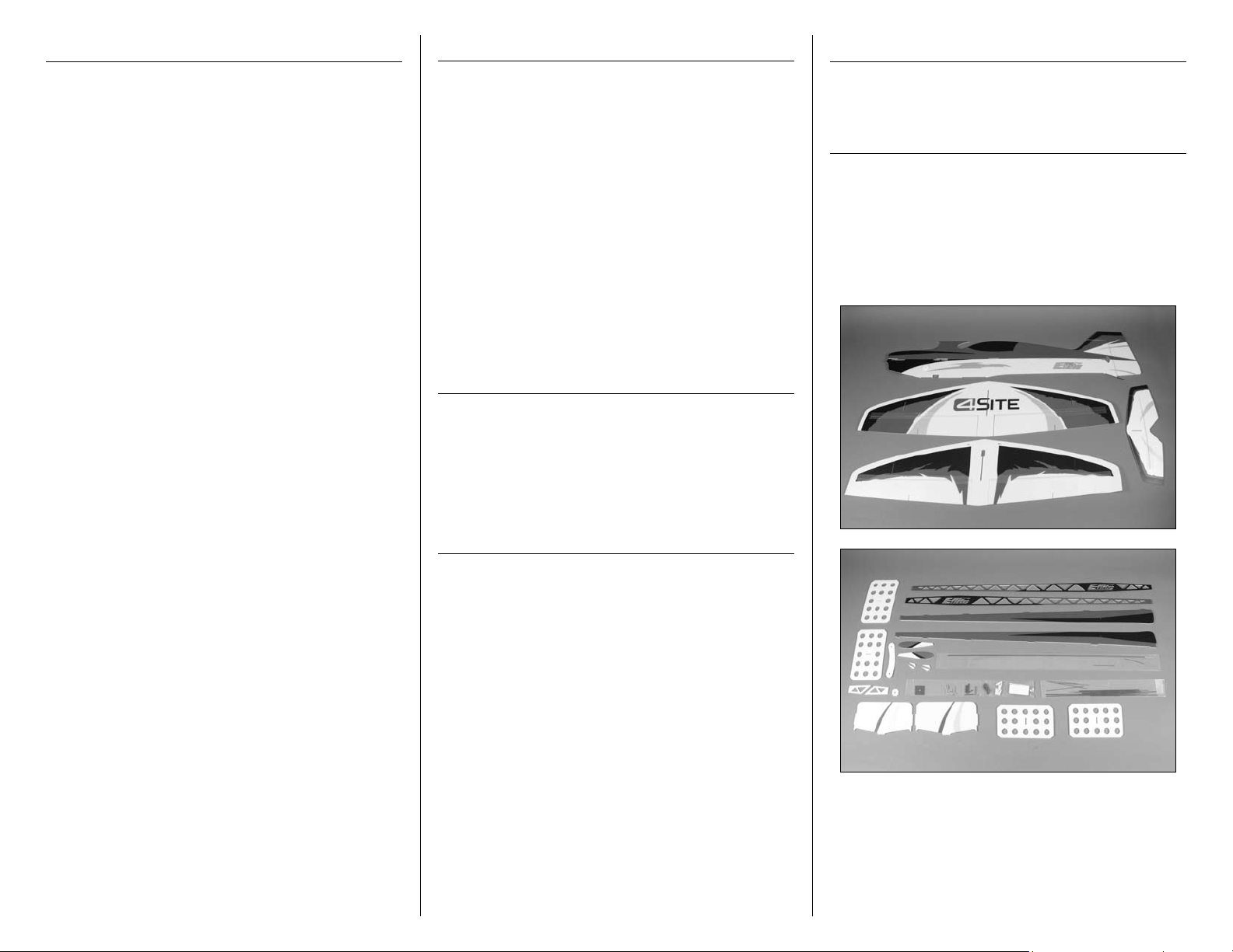
Table of Contents
Introduction
Product Registration
Introduction ........................................................... 2
Important Warranty Information .............................. 2
Using the Manual ................................................... 2
Product Registration................................................ 2
Contents of Kit/Parts Layout .................................... 2
Recommended Radio Equipment ............................. 3
Important Information About Motor Selection ........... 3
Outrunner Setup (E-flite) ......................................... 3
Required Tools and Adhesives ................................. 3
Optional Accessories .............................................. 3
Note on Lithium Polymer Batteries ........................... 3
Fuselage Construction ............................................. 4
Wing Installation .................................................... 7
Carbon Bracing Installation ..................................... 9
Landing Gear Installation ...................................... 11
Motor Installation ................................................. 13
Control Horn Installation ....................................... 14
Radio and Linkage Installation .............................. 16
Final Assembly ..................................................... 21
Airbrake Assembly (Optional) ............................... 22
Control Throws..................................................... 23
Center of Gravity ................................................. 23
Preflight ............................................................... 24
Range Test Your Radio .......................................... 24
Safety Do’s and Don’ts for Pilots ............................ 24
Flying Your 4-Site ................................................. 24
Warranty Information ........................................... 25
Instructions for Disposal of WEEE by
Users in the European Union ............................ 26
2008 Official Academy of
Model Aeronautics Safety Code ....................... 26
Thank you for purchasing the E-flite® 4-Site™ F3P.
The 4-Site is an attractive, easy-to-assemble, flat
foam model that offers incredible precision and
aerobatic flight characteristics. Constructed primarily
of 3mm Depron foam, the 4-Site also offers a high
level of prefabrication, including pre-beveled parts,
pre-hinged control surfaces and a highly visible,
pre-printed trim scheme. The lightweight, laser-cut
Depron foam construction, carbon fiber support rods
and carbon fiber motor mount set the standard for
quality, durability and performance. The 4-Site also
includes two different sets of speed brakes for optimal
personalized flying styles. For anyone looking for an
extremely lightweight, indoor foamie that excels in
precision aerobatic flight and is easy to assemble, the
4-Site flies over the competition.
Important Warranty Information
Please read our Warranty and Liability Limitations
section on Page 25 before building this product. If you
as the Purchaser or user are not prepared to accept the
liability associated with the use of this Product, you are
advised to return this Product immediately in new and
unused condition to the place of purchase.
Using the Manual
This manual is divided into sections to help make
assembly easier to understand, and to provide breaks
between each major section. In addition, check boxes
have been placed next to each step to keep track
of its completion. Steps with a single circle () are
performed once, while steps with two circles ( )
indicate that the step will require repeating, such as for
a right or left wing panel, two servos, etc.
Register your product online at:
www.e-fliterc.com/register/
Contents of Kit/Parts Layout
EFL1201 Motor Mount/Firewall
EFL1202 Carbon Pushrod Set
EFL1203 Carbon Bracing and
Landing Gear
EFL1204 Wheel Pants
EFL1180 Pushrod Supports (Wood)
EFL1181 Landing Skids, 2.5mm
Remember to take your time and follow the directions.
2 E-flite 4-Site Assembly Manual
Page 3
Recommended Radio Equipment
You will need a minimum 4-channel transmitter,
receiver, and three servos. You can also choose to
purchase a complete radio system. If you are using an
existing transmitter, just purchase the other required
equipment separately. We recommend the crystalfree, interference-free Spektrum™ DX6i 2.4GHz DSM®
6-channel system. If using your own transmitter, we
recommend the 6.0 Gram Super Sub-Micro Digital
Programmable Servos from Spektrum.
If you own the Spektrum DX6i radio, just add the
AR6300 DSM2
Spektrum 6.0 Gram Super Sub-Micro Digital
Programmable Servos.
Transmitter and Receiver
SPM6600 DX6i 6-Channel DSM2 without
Or Purchase Separately
SPMAR6300F AR6300 DSM2 Nanolite
Or
SPMDSP60 6.0 Gram Super Sub-Micro
SPMAR6300 AR6300 DSM2 Nanolite
™
6-channel receiver and three
Servos, Mode 2
6-Channel Receiver FlightPack
with four DSP60J servos (only
three servos are required for
the 4-Site)
Digital Prog Servo (3)
6-Channel Receiver, Air
Important Information About Motor
Selection
We recommend the E-flite® Park 250 Brushless
Outrunner Motor 2200Kv (EFLM1130) to provide you
with lightweight precision F3P performance.
Outrunner Setup (E-flite)
EFLM1130 Park 250 Brushless Outrunner
Motor, 2200Kv
EFLA1010 10-Amp Pro Brushless ESC
GWSEP8040B 8x4 Direct Drive Propeller
THP3502SJPL2 350mAh 2-Cell 7.4V 20C
Pro Lite V2 Li-Po, JST
Required Tools and Adhesives
Tools & Equipment
Clear tape Felt-tipped pen
T-pin Hobby knife (#11 blade)
Low-tack tape Low-temperature glue gun
Round file Ruler
Sandpaper Side cutters
Soldering iron Square
Flat blade screwdriver, small
Phillips screwdriver: #0, #1
Adhesives
Foam-safe CA and Activator (EFLA208)
Thin CA
Optional Accessories
Note on Lithium Polymer Batteries
Lithium Polymer batteries are significantly
more volatile than alkaline or Ni-Cd/
Ni-MH batteries used in RC applications.
All manufacturer’s instructions and warnings
must be followed closely. Mishandling of
Li-Po batteries can result in fire. Always
follow the manufacturer’s instructions when
disposing of Lithium Polymer batteries.
During the course of building your model we suggest
that you use a soft base for the building surface.
Such things as a foam stand, large piece of bedding
foam or a thick bath towel will work well and help
protect the model from damage during assembly.
The most important part of building your
model is guaranteeing that it is straight when
completed. A flat work surface and square will
be the most important items during this build.
The Spektrum trademark is used with permission
of Bachmann Industries, Inc.
EFLA110 Power Meter
EFLC3005 Celectra™ 1–3 Cell
Li-Po Charger
EFLC505 Intelligent 1- to 5-Cell
Balancing Charger
3E-flite 4-Site Assembly Manual
Page 4
Fuselage Construction
Landing gear doubler
Work surface
Required Parts
Main fuselage Stabilizer
Depron firewall Left horizontal fuselage
Right horizontal fuselage
Left upper diagonal brace
Right upper diagonal brace
Left lower diagonal brace
Required Tools and Adhesives
Square Foam-safe CA
If you lay the fuselage on the edge of a flat surface
so that the landing gear doubler is hanging
off of the edge and just the top half above that
is on the table it will allow you to keep the
fuselage very straight during the first steps.
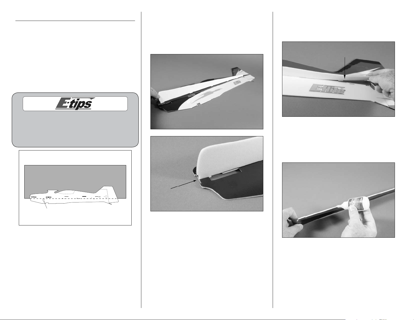
1. Locate the left horizontal fuselage and main
fuselage. The left horizontal fuselage will be
printed on top and white on the bottom. Test fit the
horizontal fuselage to the main fuselage. Check
that the horizontal fuselage lines up at the front
with the main fuselage.
2. When gluing the horizontal fuselage to the main
fuselage, do not apply glue toward the tail after
the last tab. This is necessary to properly install the
horizontal stabilizer.
3. Remove the horizontal fuselage from the main
fuselage. Apply a bead of foam-safe CA to the
left horizontal fuselage where it contact the main
fuselage. Do not apply CA to the rear section of the
horizontal fuselage as noted in the previous step.
4 E-flite 4-Site Assembly Manual
Page 5
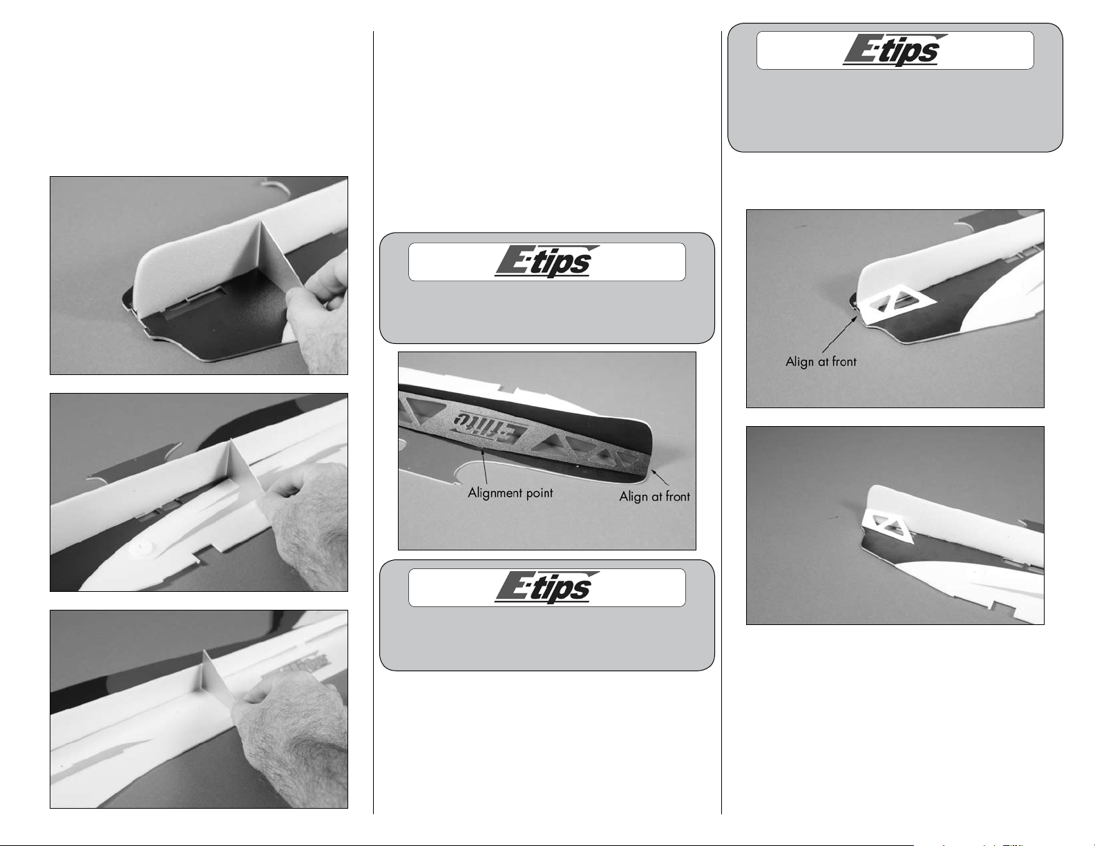
4. Position the horizontal fuselage on the main
fuselage, again making sure that they line up
at the front. Use a square at multiple points on
the fuselage from nose to tail to guarantee the
horizontal fuselage is square to the main fuselage.
Check square from both the top and bottom side
of the fuselage. Allow the CA to fully cure before
proceeding.
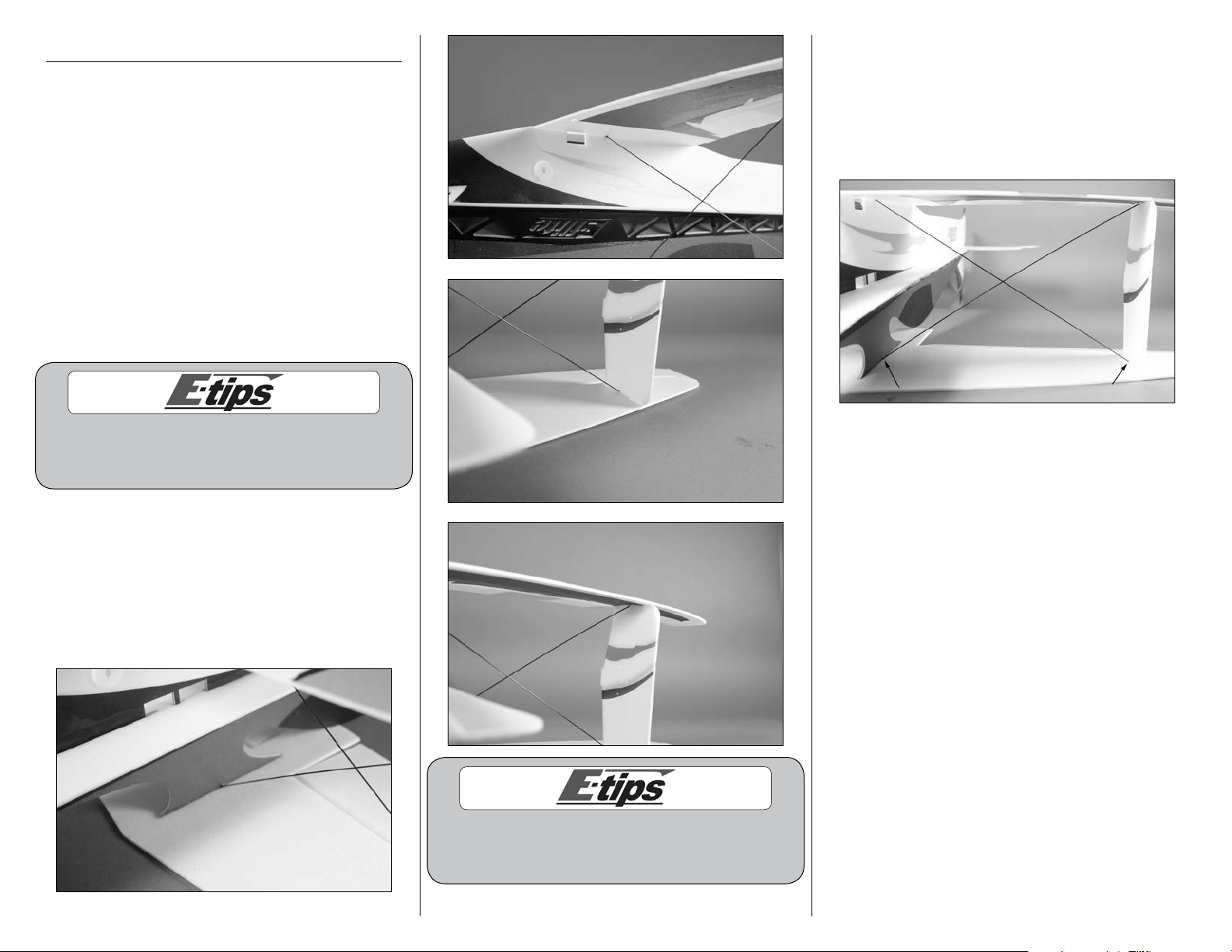
5. Position the left upper diagonal brace as shown.
Use the alignment point in the photo to properly
position the brace. The brace will just cover the
holes when aligned properly. Also make sure it
is aligned at the front of the fuselage. The angle
of the brace will be 45° to the fuselage sides
and will be equal distance on both the horizontal
and vertical fuselage. Use foam-safe CA to glue
the diagonal brace to the main and horizontal
fuselage. Do not apply CA to the rear section of
the diagonal brace, similar to that of the horizontal
fuselage.
You can temporarily use the foam firewall to
locate and mark the angle of the diagonal
brace at the front of the fuselage.
Make sure that while you are gluing the
diagonal brace to the fuselage you do not put
a lot of pressure on the assembly. You could
create a warp in the fuselage assembly.
6. Use foam-safe CA to glue the left lower diagonal
brace as shown.
Make sure to use a square on the bottom side of
the horizontal fuselage when gluing the diagonal
brace to the vertical and horizontal fuselage.
5E-flite 4-Site Assembly Manual
Page 6
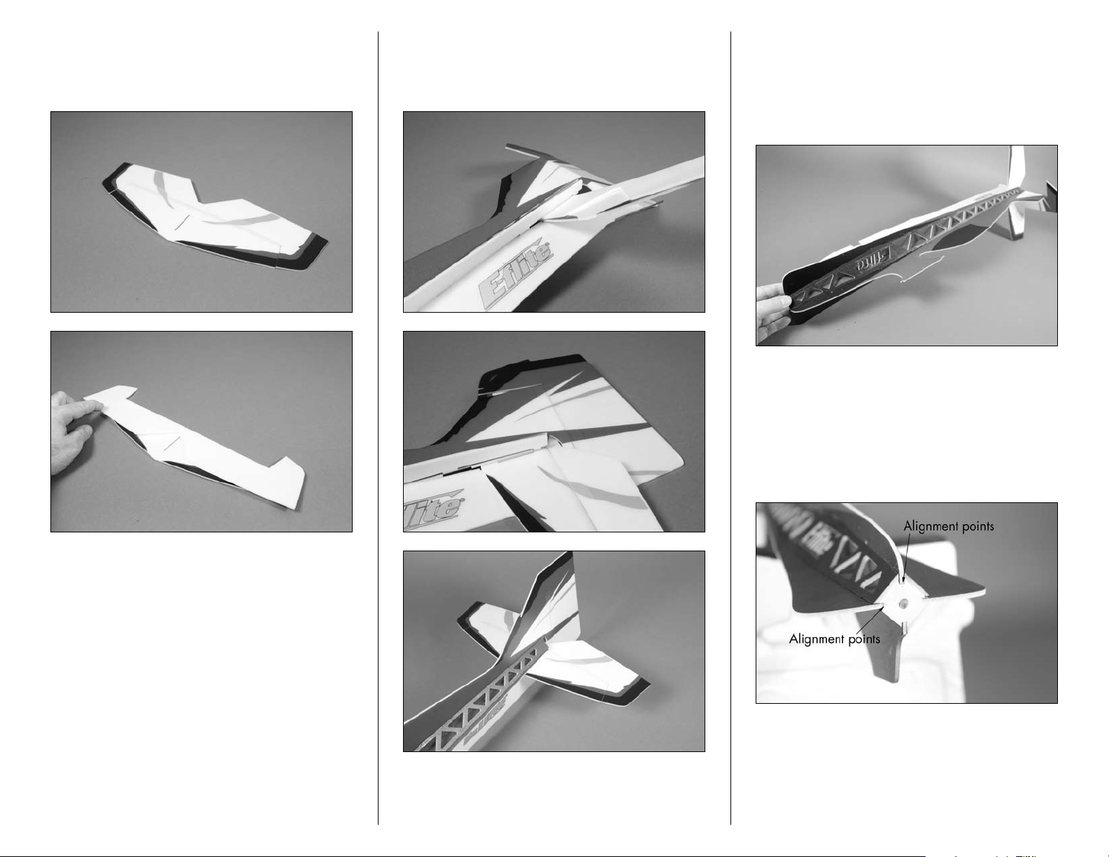
7. Locate the horizontal stabilizer. Note the coloring
scheme on the top of the stabilizer. Carefully fold
the elevator on the stabilizer as shown so it can be
installed into the fuselage.
8. Slide the folded horizontal stabilizer into
the fuselage. Unfold the elevator and position
the stabilizer, but do not apply any glue to the
stabilizer at this time.
9. Repeat Steps 1 though 5 to install the right
upper diagonal fuselage brace with foam-safe CA.
Again, make sure to work slowly and use a square
to keep the alignment of your fuselage in check.
You will not glue the lower right diagonal brace
until later in the build.
10. Locate the Depron firewall. Note the alignment
points on the firewall and how they relate to
fuselage. The alignment points are located on
the top and left (as viewed from the front of the
fuselage) as up and right thrust are built into your
model. Use foam-safe CA to install the Depron
firewall in the fuselage.
6 E-flite 4-Site Assembly Manual
Page 7
Wing Installation
Required Parts
Fuselage assembly Top wing
Bottom wing Outer strut (2)
Required Tools and Adhesives
Square Foam-safe CA
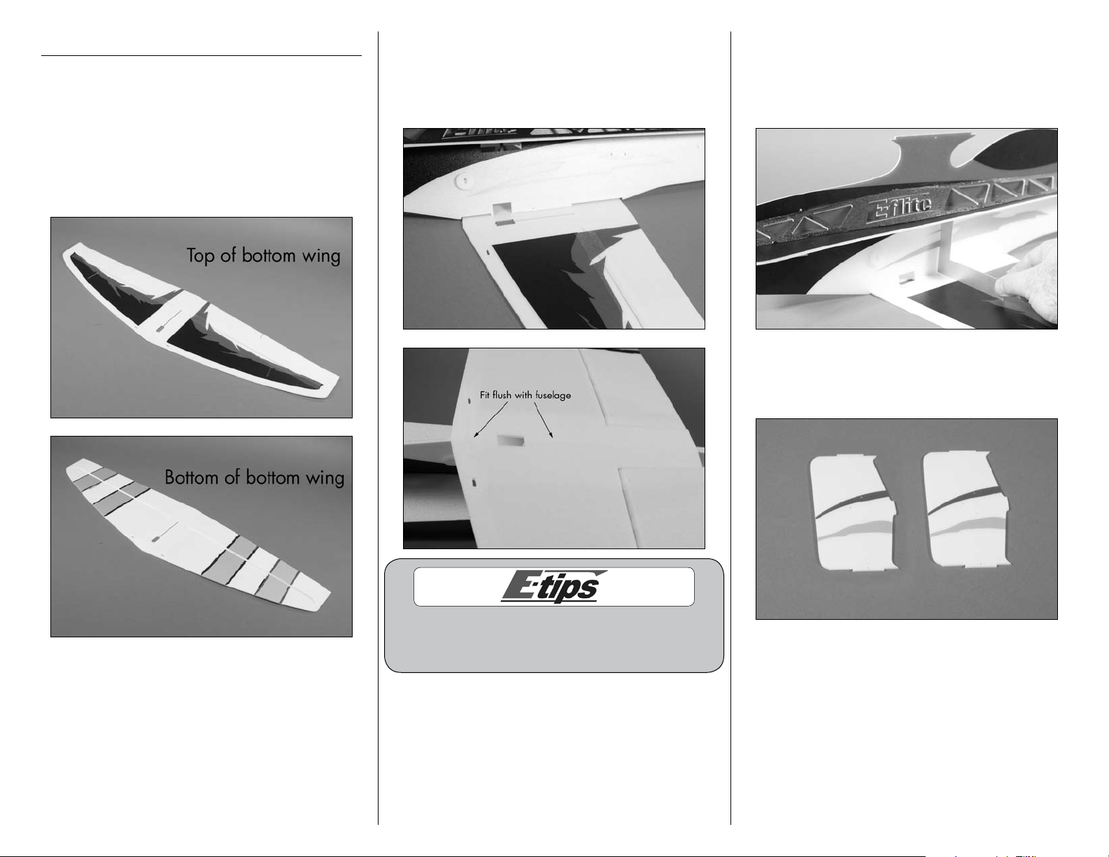
1. Locate the bottom wing.
2. Test fit the fuselage into the bottom wing as
shown. Make sure the tabs from the fuselage are
flat when inserted into the bottom wing. If not, you
may induce an airfoil resulting in unwanted flight
characteristics.
3. After confirming the fit between the fuselage
and bottom wing, use foam-safe CA to glue the
bottom wing to the fuselage. Use a square between
the fuselage and bottom wing to keep them in
alignment while the CA fully cures.
4. Locate the two outer struts. There is not a left
or right strut, but you will want to match the trim
scheme from right to left for aesthetics.
If the tail of your airplane is hanging off of the table
when you are mounting the bottom and top wing it will
allow the assembly to lay perfectly flat against the joint.
7E-flite 4-Site Assembly Manual
Page 8
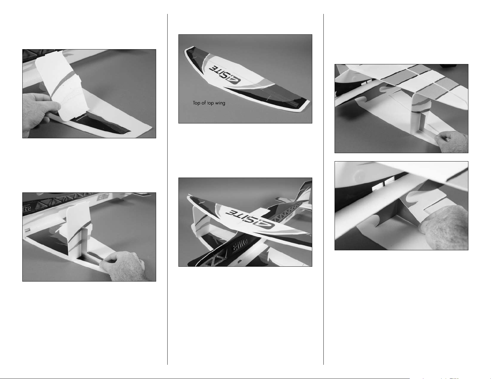
5. Test fit the outer strut into the bottom wing as
shown. Make sure the tab is flat when inserted into
the bottom wing. If not, you may induce an airfoil
resulting in unwanted flight characteristics.
6. After confirming the fit between the outer strut
and bottom wing, use foam-safe CA to glue the
outer strut to the wing. Use a square between
the outer strut and bottom wing to keep them in
alignment while the CA fully cures.
8. Locate the top wing. The bottom side of the top
wing is white with no trim scheme.
9. Test fit the top wing to the fuselage and outer
struts. The tab on the struts and fuselage will
be flat in the top wing. If not, it may induce an
unwanted airfoil that could result in unwanted flight
characteristics.
10. Remove the top wing and place it upside down
on your flat work surface. Use foam-safe CA to
glue the top wing to the fuselage and outer struts.
Make sure to use a square at both the struts and
fuselage to keep things in alignment while the CA
cures.
7. Repeat Steps 5 and 6 to install the remaining
outer strut. Make sure to match the trim scheme on
the struts on each side or your flying buddies will
laugh at you.
8 E-flite 4-Site Assembly Manual
Page 9
Carbon Bracing Installation
Required Parts
Airframe assembly
12 3/4 x 1/32-inch (325mm x 1mm) carbon rod,
Main wing bracing (4)
4 1/8 x 1/32-inch (105mm x 1mm) carbon rod,
Outer strut to tip bracing (4)
5 5/16 x 1/32-inch (135mm x 1mm) carbon rod,
Top wing to fuselage bracing (2)
5 3/4 x 1/32-inch (145mm x 1mm) carbon rod,
Horizontal tail to fuselage bracing (2)
Required Tools and Adhesives
Square Foam-safe CA
T-pin
2. With the top wing flat on your work surface,
check that the struts and fuselage are square to the
top and bottom wings. Apply a small amount of
foam-safe CA at the points where the carbon rod
are inserted in the top wing. The rod should be
inserted completely through the wing but should not
protrude past the top of the wing.
When installing the carbon rods, twisting them with
your fingers while inserting them in the hole will help
to smooth the exit and entry of the carbon rod.
1. Use the following images to position the four
pieces of 12 3/4 x 1/32-inch (325mm x 1mm)
carbon rod (two pieces on either side of the
fuselage) that keep the top and bottom wings in
alignment with the fuselage. Do not apply CA until
instructed. The rod that runs from the top of the
center cabane to the lower outer strut should be on
the front of the cross.
3. Make sure to keep the airframe very square
while proceeding. Apply a few drops of foam-safe
CA to the carbon rods where they enter the bottom
wing. Also apply CA to the junction between the
carbon rods where they cross each other. You can
trim off any excess rod from the bottom of the wing
after all four rods have been glued at each joint.
When positioning the fuselage upside down on your
work surface, the fin will need to hang off the edge of
your work surface to keep the top wing perfectly flat.
9E-flite 4-Site Assembly Manual
Page 10
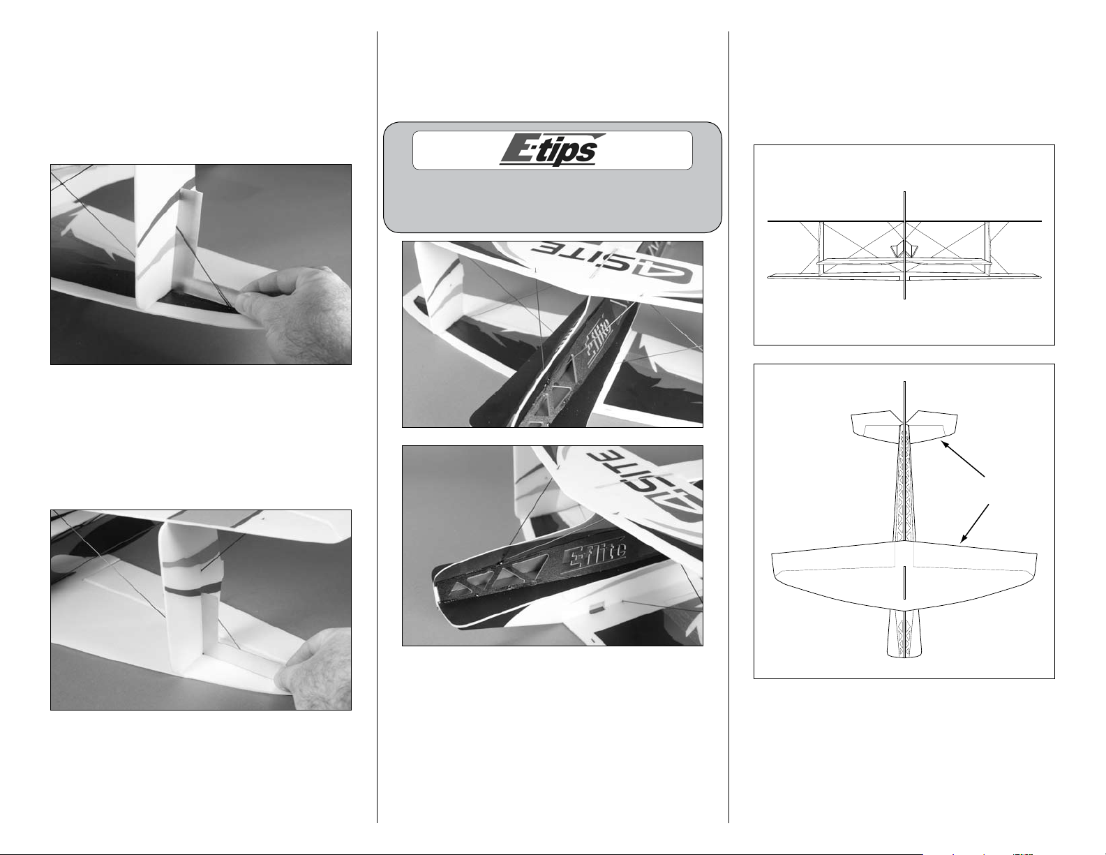
4. Using a square, install the 4 1/8 x 1/32-inch
Adjust stabilizer parallel to wings
Adjust perpendicular
to fuselage
(105mm x 1mm) carbon rods between the left and
right outer struts and bottom wing as shown. Make
sure to keep the bottom wing flat on your work
surface and not to deflect the outer struts between
the top and bottom wings when installing the
carbon rods.
5. Install the remaining 4 1/8 x 1/32-inch (105mm
x 1mm) carbon rods between the left and right
outer struts and top wing as shown. Make sure to
keep the top wing flat and not to deflect the outer
struts between the top and bottom wings when
installing the carbon rods.
6. Use foam-safe CA to install the two 5 5/16 x
1/32-inch (135mm x 1mm) carbon rods between
the top wing and fuselage as shown. Use care not
to induce any warps in the top wing while installing
the braces.
These two (2) rods affect the wing in many different
ways. Use caution to make sure that the wing stays
flat and is also still perpendicular to the fuselage.
7. Check the alignment between the wings and
stabilizer. Position the stabilizer so it is parallel to
both the top and bottom wings as shown. It should
also be square to the fuselage. Check to make sure
that the wing and stabilizer are also perpendicular
to the fuselage.
10 E-flite 4-Site Assembly Manual
Page 11

8. While keeping the stabilizer in alignment,
apply foam-safe CA to the left and right horizontal
fuselage as well as the left and right diagonal
braces to secure them to the fuselage and stabilizer.
9. Use a T-pin to poke a hole through the hinge
tape at the hole where the carbon bracing for the
stabilizer will go through.
10. Use foam-safe CA to install the two 5 3/4 x
1/32-inch (145mm x 1mm) carbon rods that
brace the stabilizer. Use the drawing from Step 8
as a guide for positioning the stabilizer. It must be
parallel to the top and bottom wings, as well as
straight across and flat as shown. You can also use
a square to help with this alignment.
Landing Gear Installation
Required Parts
Assembled airframe
6 7/8 x 3/32-inch (175mm x 2.5mm) carbon rod,
Main landing gear (2)
Landing gear support
Wheel skid (2)
Required Tools and Adhesives
Sandpaper Foam-safe CA
Thin CA
1. Use foam-safe CA to glue the landing gear
support to the bottom of the bottom wing. Make
sure the support is aligned with the leading edge of
the wing and the center points are aligned.
11E-flite 4-Site Assembly Manual
Page 12

2. Use medium grit sandpaper to sand an angle
on one end of each of the two 6 7/8 x 3/32-inch
(175mm x 2.5mm) carbon rods. This angle should
be around 45-degrees and will allow the carbon
rods to fit against each other to provide a much
stronger landing gear assembly.
3. Test fit the two carbon rods in the aircraft as
shown. Once the fit is acceptable, and the airframe
will sit level, use foam-safe CA to glue the carbon
rods into position. Allow the CA to fully cure before
proceeding.
4. Test the fit of the two wheel skids on the ends of
the carbon rods. The skids will be parallel to the
fuselage when installed correctly. Use thin CA to
glue the skids to the carbon rods.
12 E-flite 4-Site Assembly Manual
Page 13

Motor Installation
Required Parts
Assembled airframe Carbon firewall
Motor Receiver
Transmitter Motor battery
Speed control
Right lower diagonal brace
Required Tools and Adhesives
Foam-safe CA Sandpaper
Flat blade screwdriver, small
Phillips screwdriver, #1
Hobby knife with #11 blade or round file
1. Locate the carbon firewall. There are four
holes in the firewall: two large and two small.
The two smaller holes are the alignment points for
positioning the firewall on the fuselage. These holes
will be located just like the ones on the Depron
firewall.
2. Use medium grit sandpaper to lightly sand
the back side of the firewall. The glue will be
applied to this side of the firewall to attach it to
the fuselage.
3. Match the two alignment points to those in the
Depron firewall (top and left as viewed from the
front of the fuselage). Use foam-safe CA to secure
the firewall to the fuselage.
4. It may be necessary to remove a small amount
of material from behind the firewall to clear the
motor shaft of your particular motor. You can use
either a round file or hobby knife to accomplish this
task.
5. Attach the motor mount to the motor following
the instructions provided with the motor using a flat
blade screwdriver. Note the position of the motor
wires in relation to the motor, as they need to be
positioned as such to connect to the speed control.
13E-flite 4-Site Assembly Manual
Page 14

6. Use a #1 Phillips screwdriver and the two screws
provided with your motor to attach it to the firewall.
Work slowly to avoid applying too much pressure,
resulting in damage to your airframe.
8. Check the operation of the motor at this time.
It should rotate counterclockwise when viewed
from the front of the aircraft. If not, follow the
instructions provided with your speed control to
correct the situation.
Never check the motor rotation on the bench
with the propeller installed. The plane could
move and cause serious injury. Always check the
motor without the propeller to avoid injury.
Control Horn Installation
Required Parts
Assembled airframe Depron control horn support
(4)
13/16 x 1/16-inch (20mm x 1mm) carbon rod,
control rod (4)
Required Tools and Adhesives
Foam-safe CA Hobby knife
Felt-tipped pen Low-tack tape
Ruler T-pin
7. Pass the motor wires through the slot in the front
of the fuselage. Connect the wires from the motor
to those of the speed control. The battery lead
from the speed control can now be passed to the
opposite side of the fuselage through the slot in the
fuselage as well.
9. Use foam-safe CA to glue the right lower
diagonal brace on the fuselage.
10. The speed control should be positioned
between the two braces as shown.
1. Use a ruler and felt-tipped pen to measure
and mark the four 13/16 x 1/16-inch (20mm
x 1mm) carbon rods 19/32-inch (15mm) from
the end of each rod.
14 E-flite 4-Site Assembly Manual
Page 15

2. Use foam-safe CA to glue a carbon rod to
19/32-inch
(15mm)
the control horn support as shown. Assemble
four control horns at this time.
Cut small pieces of low-tack tape and use
them to keep the control surfaces stationary
while installing the control horns and linkages.
Make sure not to apply tape to any colored
surfaces as it will damage the trim scheme.
3. Use a T-pin to poke a hole in the hinge tape for
each of the bottom ailerons, rudder and elevator.
4. Use foam-safe CA to glue the control
horns in position. Make sure the control horn
supports are perpendicular to the hinge line
on each of the control surfaces.
15E-flite 4-Site Assembly Manual
Page 16

Radio and Linkage Installation
Required Parts
Assembled airframe Transmitter
Receiver Heat shrink (8)
Servo (3) Receiver
3D Servo arm (3) Hook and loop tape
23 5/8-inch (600mm) rudder and elevator
carbon pushrod (2)
3 1/2-inch (90mm) aileron carbon pushrod (2)
6 7/8-inch (175mm) aileron link carbon rod (2)
1 x 3/32-inch (25mm x 2mm) carbon rod,
aileron control horn (4)
Required Tools and Adhesives
Foam-safe CA Phillips screwdriver, #0
Soldering iron Clear tape
Side cutters Low-temperature glue gun
1. Plug the rudder, elevator and aileron servos into
their corresponding ports of the receiver. Starting
with a new model, turn on the radio to center the
servos. Use a #0 Phillips screwdriver to remove the
original arms from the servos and install the long
3D arms.
4. Prepare the elevator servo by removing the
unused arm from the servo horn as shown.
There are more ways to lighten the 4-Site. Some
of these options will void the warranty for the
products used. These steps are covered in the E-flite
Enticement manual which can be found on the
Enticement product page at www.horizonhobby.com.
2. Prepare the rudder servo by removing the
unused arm from the servo horn as shown.
5. Test fit the elevator servo in the remaining hole
in the main fuselage. The output of the servo will
face the tail of the aircraft. Once fit, use a lowtemperature glue gun or foam-safe CA to adhere
the servo to the fuselage.
3. Test fit the rudder servo in the rear hole in the
main fuselage. The output of the servo will face the
tail of the aircraft. Once fit, use a low-temperature
glue gun or foam-safe CA to adhere the servo to
the fuselage.
16 E-flite 4-Site Assembly Manual
Page 17

6. Test fit the aileron servo in the hole in the bottom
Not to scale
9/16-inch
(14mm)
of the bottom wing. The output of the servo will
face the tail of the aircraft. Once fit, use a lowtemperature glue gun or foam-safe CA to adhere
the servo to the wing.
7. Plug the servos into the receiver at this time.
You may need to plug an adapter in the receiver
to connect the lead from the speed control as well.
Use hook and loop tape to secure the receiver to
the fuselage.
8. Insert the bend of the 23 5/8-inch (600mm)
rudder pushrod into the servo arm. Use the third
hole in from the end of the servo arm as shown.
It is possible for the ends of the pushrods to
come loose in packaging and shipping. It is a
good practice to check these ends. If they are
loose, reglue the ends by placing a drop of
foam-safe CA at each end of the heat shrink.
Use clear tape to neatly organize the servo leads.
It might be easier to insert the pushrod if you remove
the horn from the servo. If this is done, just make sure
that you center it when placing it back on the servo.
17E-flite 4-Site Assembly Manual
Page 18

9. Locate three of the pushrod supports and slide
the supports onto the pushrod as shown in the
second photo.
11. Align the pushrod with the rudder control horn.
12. The pushrod is supplied slightly long to
accommodate for servo selection and control horn
position. Use side cutters to trim the pushrod so it
almost touches the rudder control horn.
13. Slide a piece of heat shrink on the pushrod
and control horn.
Only use a soldering iron to shrink the
tubing for the control rods. A heat gun or
lighter will damage the control surfaces.
Use care not to touch the soldering iron
to any of the control surfaces.
You will notice that there is extra heat shrink
supplied with the kit. This is in case you
10. Insert the pushrod guides into the slots in the
lose one or need to redo a linkage.
fuselage. In each position, there is a pair of holes.
The rudder pushrod supports go in the rear hole of
each pair. Do not glue the supports yet.
18 E-flite 4-Site Assembly Manual
Page 19

14. Use a soldering iron to shrink the tubing to
Not to scale
11/16-inch
(17mm)
Not to scale
3/4-inch
(19mm)
3/4-inch
(19mm)
secure the pushrod to the control horn.
16. Insert the bend of the 23
5
/8-inch (600mm)
elevator pushrod into the servo arm. Use the
second hole in from the end of the servo arm as
shown.
18. After aligning and trimming the elevator
pushrod using side cutters, connect the pushrod to
the elevator control horn using heat shrink tubing
and a soldering iron.
15. Go back and align the supports so that the
pushrod is straight, and glue them in using foamsafe CA.
17. Insert the pushrod guides into the slots in the
fuselage. In each position, there is a pair of holes.
The elevator pushrod supports will be flush with the
opposite side of the fuselage when installed. Do not
glue the supports at this time.
19. Go back and align the supports so that the
pushrod is straight and glue them in using foamsafe CA.
20. The installation of the aileron pushrod follows
the same procedure as the elevator and rudder
pushrods, only without the supports.
19E-flite 4-Site Assembly Manual
Page 20

21. Once the pushrods are connected to the control
horns, apply a drop of foam-safe CA to the heat
shrink tubing. Apply CA to both the pushrod and
control horn side to secure the tubing to each.
22. Use foam-safe CA to glue the two 1 x 3/32-
inch (2 x 25mm) carbon rods in the slots in the
top and bottom ailerons. Make sure the rods
are parallel and centered with the ailerons when
installed.
23. Connect the 6 7/8-inch (175mm) carbon rod to
the control horn of the upper aileron using a piece
of heat shrink and a soldering iron.
24. Use side cutters to trim the carbon rod to the
proper length. Use a piece of heat shrink and a
soldering iron to make the connection between the
top and bottom ailerons.
25. Apply a drop of foam-safe A to the heat shrink
at both the top and bottom ailerons. Make sure to
apply CA to both the pushrod and control horn.
26. Repeat Steps 22 through 25 to connect the
remaining top and bottom aileron.
27. Remove the tape used to keep the control
surfaces centered at this time.
20 E-flite 4-Site Assembly Manual
Page 21

Final Assembly
Required Parts
Assembled airframe Propeller
Propeller adapter Wheel pant (2)
Motor battery Hook and loop tape
Required Tools and Adhesives
Foam-safe CA
Important Information About Your Propeller
It is very important to check to be sure the
propeller is balanced before installing onto the
shaft. An unbalanced propeller may strip the
gears or cause poor flight characteristics.
If it is necessary to enlarge the hole in
the propeller or the spinner, make sure to
check the balance of each afterwards.
1. Locate the propeller adapter (included with
motor) that fits your particular model. Insert the
adapter in the propeller, making sure it is installed
in the backside of the propeller.
2. Mount the propeller following the instructions
provided with your motor.
3. Foam-safe CA is used to glue the wheel pants
to the wheel skids. A small notch in the wheel pant
will align with the center ridge on the wheel skid.
Make sure there is clearance between your work
surface and the wheel pants so they do not rub
during take-off or landing.
4. Use scissors to cut a 25mm piece of hook and
loop tape. Peel the backing from the softer side and
attach it to the battery.
5. The battery attaches roughly 25mm in front
of the elevator servo. The exact position can be
adjusted to correct the Center of Gravity if it is not
correct according to this manual.
21E-flite 4-Site Assembly Manual
Page 22

Air Brake Assembly (Optional)
Required Parts
Assembled airframe
3 3/8-inch (80mm) air brake support carbon rod (4)
Air brake, large (2)
Air brake, small (2)
Required Tools and Adhesives
Square Foam-safe CA
1. Locate the large and small air brakes. The air
brakes are an optional part. There are two different
size air brakes supplied with the 4-Site. If you
are interested in flying more aggressive 3D style
maneuvers you may want to leave these off. If you
fly mainly in a large indoor facility, then you will
want to use the smaller air brakes. If you fly in a
smaller area like a one court size gym, then the
larger air brakes will slow the 4-Site down more.
You may choose to try all three variations. Do
this by just lightly tack gluing the air brakes on at
first. Choose the set of air brakes that suits your
particular flying location and flying style.
2. Use foam-safe CA to glue the air brake to the
outer strut. Use a square to align the air brake with
the outer strut as shown.
4. Repeat Steps 2 and 3 to install the remaining
matching air brake.
3. Use two 3 3/8-inch (80mm) carbon rods to
support the air brake and keep it from changing
angle. The carbon rods are glued using foam-safe
CA. Use a square to check that the air brake is still
square to the outer strut before the CA fully cures.
22 E-flite 4-Site Assembly Manual
Page 23

Control Throws
1. Turn on the transmitter and receiver of your
model. Check the movement of the rudder using
the transmitter. When the stick is moved right,
the rudder should also move right. Reverse the
direction of the servo at the transmitter if necessary.
2. Check the movement of the elevator with the
radio system. Moving the elevator stick toward the
bottom of the transmitter will make the airplane
elevator move up.
3. Check the movement of the ailerons with the
radio system. Moving the aileron stick right will
make the right aileron move up and the left aileron
move down.
4. Use a ruler to adjust the throw of the elevator,
ailerons and rudder.
Aileron High Rate
Up 2 1/8-inch (55mm)
Down 2 1/8-inch (55mm)
Aileron Low Rate
Up 1 3/16-inch (30mm)
Down 1 3/16-inch (30mm)
Elevator High Rate
Up 1
3
/4-inch (45mm)
Down 1 3/4-inch (45mm)
Elevator Low Rate
Up 1 3/16-inch (30mm)
Down 1 3/16-inch (30mm)
Rudder High Rate
Up 3 1/8-inch (80mm)
Down 3 1/8-inch (80mm)
Rudder Low Rate
Up 2-inch (50mm)
Down 2-inch (50mm)
You will notice that when you get to the full travel of
high rates on the aileron servo you will see a slight
difference in the travel amount from top to bottom due
to the servo linkage offset. This does not affect the
flight performance of the 4-Site.
Center of Gravity
An important part of preparing the aircraft for flight is
properly balancing the model.
Caution: Do not inadvertently skip this step!
The recommended Center of Gravity (CG) location
for your model is 2 7/8 to 3 9/16 inches (75–90mm)
back from the leading edge of the top wing at the
center. Make sure to measure from the farthest point
forward for accuracy. Mark the location for the Center
of Gravity on the bottom of the top wing next to the
fuselage as shown.
Adjust components as necessary so the model hangs
level or slightly nose down. This is the correct balance
point for your model. You might find that you need to
shift the battery slightly to either the front or back of
the fuselage to achieve the correct balance.
Measurements are taken at the inner or
widest point on the control surface.
These are general guidelines measured from our own
flight tests. You can experiment with higher rates to
match your preferred style of flying.
Travel Adjust, Sub Trim and Dual Rates are
not listed and should be adjusted according
to each individual model and preference.
After the first flights, the CG position can be adjusted
for your personal preference.
You can use a small ball driver or pen to
hold the 4-Site up during balancing.
23E-flite 4-Site Assembly Manual
Page 24

Preflight
Range Test Your Radio
Flying Your 4-Site
Check Your Radio
Before going to the field, be sure that your batteries
are fully charged per the instructions included with
your radio. Charge both the transmitter and receiver
pack for your airplane. Use the recommended charger
supplied with your particular radio system, following
the instructions provided with the radio. In most cases,
the radio should be charged the night before going
out flying.
Before each flying session, be sure to range check your
radio. See your radio manual for the recommended
range and instructions for your radio system. Each
radio manufacturer specifies different procedures for
their radio systems. Next, start the motor. With the
model securely anchored, check the range again.
The range test should not be significantly affected. If
it is, don’t attempt to fly! Have your radio equipment
checked out by the manufacturer.
Note: Keep loose items that can get entangled
in the propeller away from the prop. These
include loose clothing, or other objects such as
pencils and screwdrivers. Especially keep your
hands away from the propeller.
Double-check that all controls (aileron, elevator, rudder
and throttle) move in the correct direction.
1. Before each flying session, be sure to range
check your radio. This is accomplished by turning
on your transmitter with the antenna collapsed.
Turn on the receiver in your airplane. With
your airplane on the ground and the engine
running, you should be able to walk 30 paces
(approximately 100 feet) away from your airplane
and still have complete control of all functions.
If not, don’t attempt to fly! Have your radio
equipment checked out by the manufacturer.
2. Double-check that all controls (aileron, elevator,
rudder and throttle) move in the correct direction.
3. Be sure that your transmitter batteries are
fully charged, per the instructions included with
your radio.
Flying the 4-Site is about as fun as it can get. Very light
wing loading and extreme control throws make for some
precise F3P flying. Verify that your CG is at the correct
location as per the manual and that you have your rates
set up to your liking.
Verify all control throws are in the correct direction and
the motor spins in the correct direction as well. Point the
model into the wind and add some throttle trim until the
motor begins to turn. This will be your flight idle. We
recommend hand launching the model if you are flying
from of a rough surface.
Apply power slowly. You will find the model will
become airborne very quickly and at a low speed. This
model excels at flying slow and easy. Trim the model
for level flight at half throttle. Only use full throttle for
maneuvering.
You will find you can adjust the CG to your liking by
moving the battery pack fore or aft on the fuselage.
To land the 4-Site just reduce the throttle to idle and feed
in up elevator until the model settles into a slightly nosehigh attitude.
Gently fly the model down to the landing spot with a
final flair at touchdown.
We hope you enjoy the 4-Site as much as we do.
Check the radio installation and make sure all the
control surfaces are moving correctly (i.e. the correct
direction and with the recommended throws). Test run
the motor and make sure it transitions smoothly from
off to full throttle and back. Also ensure the engine is
installed according to the manufacturer’s instructions,
and it will operate consistently.
Check all the control horns, servo horns, and clevises
to make sure they are secure and in good condition.
Repair or replace any items that would be considered
questionable. Failure of any of these components in
flight would mean the loss of your aircraft.
24 E-flite 4-Site Assembly Manual
Happy landings.
Page 25

Safety Do’s and Don’ts for Pilots
Warranty Information
DAMAGE LIMITS
• Checkallcontrolsurfacespriortoeachtakeoff.
• Donotflyyourmodelnearspectators,parking
areas or any other area that could result in injury
to people or damage of property.
• Donotflyduringadverseweatherconditions.
Poor visibility can cause disorientation and loss
of control of your aircraft. Strong winds can
cause similar problems.
• Donottakechances.Ifatanytimeduringflight
you observe any erratic or abnormal operation,
land immediately and do not resume flight until
the cause of the problem has been ascertained
and corrected. Safety can never be taken lightly.
• Donotflynearpowerlines.
Safety Precautions
This is a sophisticated hobby Product and not a toy.
It must be operated with caution and common sense
and requires some basic mechanical ability. Failure to
operate this Product in a safe and responsible manner
could result in injury or damage to the Product or
other property. This Product is not intended for use by
children without direct adult supervision. The Product
manual contains instructions for safety, operation and
maintenance. It is essential to read and follow all
the instructions and warnings in the manual, prior to
assembly, setup or use, in order to operate correctly
and avoid damage or injury.
WARRANTY PERIOD
Exclusive Warranty- Horizon Hobby, Inc., (Horizon)
warranties that the Products purchased (the “Product”)
will be free from defects in materials and workmanship
at the date of purchase by the Purchaser.
LIMITED WARRANTY
(a) This warranty is limited to the original Purchaser
(“Purchaser”) and is not transferable. REPAIR
OR REPLACEMENT AS PROVIDED UNDER THIS
WARRANTY IS THE EXCLUSIVE REMEDY OF THE
PURCHASER. This warranty covers only those Products
purchased from an authorized Horizon dealer. Third
party transactions are not covered by this warranty.
Proof of purchase is required for warranty claims.
Further, Horizon reserves the right to change or modify
this warranty without notice and disclaims all other
warranties, express or implied.
(b) Limitations- HORIZON MAKES NO WARRANTY
OR REPRESENTATION, EXPRESS OR IMPLIED,
ABOUT NON-INFRINGEMENT, MERCHANTABILITY
OR FITNESS FOR A PARTICULAR PURPOSE OF THE
PRODUCT. THE PURCHASER ACKNOWLEDGES
THAT THEY ALONE HAVE DETERMINED THAT THE
PRODUCT WILL SUITABLY MEET THE REQUIREMENTS
OF THE PURCHASER’S INTENDED USE.
(c) Purchaser Remedy- Horizon’s sole obligation
hereunder shall be that Horizon will, at its option,
(i) repair or (ii) replace, any Product determined
by Horizon to be defective. In the event of a defect,
these are the Purchaser’s exclusive remedies. Horizon
reserves the right to inspect any and all equipment
involved in a warranty claim. Repair or replacement
decisions are at the sole discretion of Horizon.
This warranty does not cover cosmetic damage or
damage due to acts of God, accident, misuse, abuse,
negligence, commercial use, or modification of or
to any part of the Product. This warranty does not
cover damage due to improper installation, operation,
maintenance, or attempted repair by anyone other
than Horizon. Return of any goods by Purchaser must
be approved in writing by Horizon before shipment.
HORIZON SHALL NOT BE LIABLE FOR SPECIAL,
INDIRECT OR CONSEQUENTIAL DAMAGES, LOSS
OF PROFITS OR PRODUCTION OR COMMERCIAL
LOSS IN ANY WAY CONNECTED WITH THE
PRODUCT, WHETHER SUCH CLAIM IS BASED IN
CONTRACT, WARRANTY, NEGLIGENCE, OR STRICT
LIABILITY. Further, in no event shall the liability of
Horizon exceed the individual price of the Product on
which liability is asserted. As Horizon has no control
over use, setup, final assembly, modification or misuse,
no liability shall be assumed nor accepted for any
resulting damage or injury. By the act of use, setup or
assembly, the user accepts all resulting liability.
If you as the Purchaser or user are not prepared
to accept the liability associated with the use of
this Product, you are advised to return this Product
immediately in new and unused condition to the place
of purchase.
Law: These Terms are governed by Illinois law (without
regard to conflict of law principals).
SAFETY PRECAUTIONS
This is a sophisticated hobby Product and not a toy.
It must be operated with caution and common sense
and requires some basic mechanical ability. Failure to
operate this Product in a safe and responsible manner
could result in injury or damage to the Product or
other property. This Product is not intended for use by
children without direct adult supervision. The Product
manual contains instructions for safety, operation and
maintenance. It is essential to read and follow all
the instructions and warnings in the manual, prior to
assembly, setup or use, in order to operate correctly
and avoid damage or injury.
25E-flite 4-Site Assembly Manual
Page 26

QUESTIONS, ASSISTANCE, AND REPAIRS
NON-WARRANTY REPAIRS
United Kingdom:
Your local hobby store and/or place of purchase
cannot provide warranty support or repair. Once
assembly, setup or use of the Product has been
started, you must contact Horizon directly. This will
enable Horizon to better answer your questions
and service you in the event that you may need any
assistance. For questions or assistance, please direct
your email to productsupport@horizonhobby.com,
or call 877.504.0233 toll free to speak to a service
technician.
INSPECTION OR REPAIRS
If this Product needs to be inspected or repaired,
please call for a Return Merchandise Authorization
(RMA). Pack the Product securely using a shipping
carton. Please note that original boxes may be
included, but are not designed to withstand the rigors
of shipping without additional protection. Ship via a
carrier that provides tracking and insurance for lost
or damaged parcels, as Horizon is not responsible
for merchandise until it arrives and is accepted at our
facility. A Service Repair Request is available at www.
horizonhobby.com on the “Support” tab. If you do
not have internet access, please include a letter with
your complete name, street address, email address
and phone number where you can be reached during
business days, your RMA number, a list of the included
items, method of payment for any non-warranty
expenses and a brief summary of the problem.
Your original sales receipt must also be included for
warranty consideration. Be sure your name, address,
and RMA number are clearly written on the outside of
the shipping carton.
WARRANTY INSPECTION AND REPAIRS
To receive warranty service, you must include your
original sales receipt verifying the proof-of-purchase
date. Provided warranty conditions have been met,
your Product will be repaired or replaced free of
charge. Repair or replacement decisions are at the sole
discretion of Horizon Hobby.
Should your repair not be covered by warranty the
repair will be completed and payment will be required
without notification or estimate of the expense unless
the expense exceeds 50% of the retail purchase cost.
By submitting the item for repair you are agreeing
to payment of the repair without notification. Repair
estimates are available upon request. You must include
this request with your repair. Non-warranty repair
estimates will be billed a minimum of 1/2 hour of
labor. In addition you will be billed for return freight.
Please advise us of your preferred method of payment.
Horizon accepts money orders and cashiers checks,
as well as Visa, MasterCard, American Express, and
Discover cards. If you choose to pay by credit card,
please include your credit card number and expiration
date. Any repair left unpaid or unclaimed after 90
days will be considered abandoned and will be
disposed of accordingly. Please note: non-warranty
repair is only available on electronics and model
engines.
United States:
Electronics and engines requiring inspection or repair
should be shipped to the following address:
Horizon Service Center
4105 Fieldstone Road
Champaign, Illinois 61822
All other Products requiring warranty inspection or
repair should be shipped to the following address:
Horizon Product Support
4105 Fieldstone Road
Champaign, Illinois 61822
Please call 877-504-0233 or e-mail us at
productsupport@horizonhobby.com with any questions
or concerns regarding this product or warranty.
Electronics and engines requiring inspection or repair
should be shipped to the following address:
Horizon Hobby UK
Units 1-4 Ployters Rd
Staple Tye
Harlow, Essex
CM18 7NS
United Kingdom
Please call +44 (0) 1279 641 097 or e-mail us at
sales@horizonhobby.co.uk with any questions or
concerns regarding this product or warranty.
Germany:
Electronics and engines requiring inspection or repair
should be shipped to the following address:
Horizon Technischer Service
Hamburger Strasse 10
25335 Elmshorn
Germany
Please call +49 4121 46199 66 or e-mail us at
service@horizonhobby.de with any questions or
concerns regarding this product or warranty.
26 E-flite 4-Site Assembly Manual
Page 27

CE Compliance Information for the
UK DE DK NO SE
FI EE LV LT PL
CZ SK HU RO SI
AT IT ES PT IE
NL LU MT CY GR
European Union
Instructions for Disposal of WEEE by Users in the
European Union
This product must not be disposed of with other waste.
Instead, it is the user’s responsibility to dispose of their
waste equipment by handing it over to a designated
collection point for the recycling of waste electrical
and electronic equipment. The separate collection
and recycling of your waste equipment at the time
of disposal will help to conserve natural resources
and ensure that it is recycled in a manner that
protects human health and the environment. For more
information about where you can drop off your waste
equipment for recycling, please contact your local city
office, your household waste disposal service or where
you purchased the product.
The associated regulatory agencies of the following
countries recognize the noted certifications for this
product as authorized for sale and use:
2008 Official Academy of Model
Aeronautics Safety Code
GENERAL
1. A model aircraft shall be defined as a nonhuman-carrying device capable of sustained
flight in the atmosphere. It shall not exceed
limitations established in this code and is
intended to be used exclusively for recreational
or competition activity.
2. The maximum takeoff weight of a model aircraft,
including fuel, is 55 pounds, except for those
flown under the AMA Experimental Aircraft
Rules.
3. I will abide by this Safety Code and all rules
established for the flying site I use. I will not
willfully fly my model aircraft in a reckless and/
or dangerous manner.
4. I will not fly my model aircraft in sanctioned
events, air shows, or model demonstrations until
it has been proven airworthy.
5. I will not fly my model aircraft higher than
approximately 400 feet above ground level,
when within three (3) miles of an airport without
notifying the airport operator. I will yield the
right-of-way and avoid flying in the proximity
of full-scale aircraft, utilizing a spotter when
appropriate.
8. I will not operate model aircraft carrying
pyrotechnic devices which explode burn, or
propel a projectile of any kind. Exceptions
include Free Flight fuses or devices that burn
producing smoke and are securely attached to
the model aircraft during flight. Rocket motors
up to a G-series size may be used, provided
they remain firmly attached to the model aircraft
during flight. Model rockets may be flown in
accordance with the National Model Rocketry
Safety Code; however, they may not be launched
from model aircraft. Officially designated AMA
Air Show Teams (AST) are authorized to use
devices and practices as defined within the Air
Show Advisory Committee Document.
9. I will not operate my model aircraft while under
the influence of alcohol or within eight (8) hours
of having consumed alcohol.
10. I will not operate my model aircraft while using
any drug which could adversely affect my ability
to safely control my model aircraft.
11. Children under six (6) years old are only allowed
on a flightline or in a flight area as a pilot or
while under flight instruction.
12. When and where required by rule, helmets
must be properly worn and fastened. They must
be OSHA, DOT, ANSI, SNELL or NOCSAE
approved or comply with comparable standards.
RADIO CONTROL
6. I will not fly my model aircraft unless it is
identified with my name and address, or AMA
number, inside or affixed to the outside of the
model aircraft. This does not apply to model
aircraft flown indoors.
7. I will not operate model aircraft with metal-blade
propellers or with gaseous boosts (other than
air), nor will I operate model aircraft with fuels
containing tetranitromethane or hydrazine.
1. All model flying shall be conducted in a manner
to avoid over flight of unprotected people.
2. I will have completed a successful radio
equipment ground-range check before the first
flight of a new or repaired model aircraft.
3. I will not fly my model aircraft in the presence of
spectators until I become a proficient flier, unless I
am assisted by an experienced pilot.
27E-flite 4-Site Assembly Manual
Page 28

4. At all flying sites a line must be established,
in front of which all flying takes place. Only
personnel associated with flying the model
aircraft are allowed at or in front of the line. In
the case of airshows demonstrations straight line
must be established. An area away from the line
must be maintained for spectators. Intentional
flying behind the line is prohibited.
5. I will operate my model aircraft using only
radio-control frequencies currently allowed by
the Federal Communications Commission (FCC).
Only individuals properly licensed by the FCC
are authorized to operate equipment on Amateur
Band frequencies.
6. I will not knowingly operate my model aircraft
within three (3) miles of any preexisting flying
site without a frequency-management agreement.
A frequency management agreement may be
an allocation of frequencies for each site, a
day-use agreement between sites, or testing
which determines that no interference exists.
A frequency-management agreement may
exist between two or more AMA chartered
clubs, AMA clubs and individual AMA
members, or individual AMA members.
Frequency-management agreements, including
an interference test report if the agreement
indicates no interference exists, will be signed
by all parties and copies provided to AMA
Headquarters.
7. With the exception of events flown under official
AMA rules, no powered model may be flown
outdoors closer than 25 feet to any individual,
except for the pilot and located at the flightline.
10. The operator of a radio-controlled model
aircraft shall control it during the entire flight,
maintaining visual contact without enhancement
other than by corrective lenses that are
prescribed for the pilot. No model aircraft shall
be equipped with devices which allow it to be
flown to a selected location which is beyond the
visual range of the pilot.
4-Site Safe Operating Recommendations
- Inspect your model before every flight to make
certain it is airworthy.
- Be aware of any other radio frequency user who
may present an interference problem.
- Always be courteous and respectful of other
users of your selected flight area.
- Choose an area clear of obstacles and large
enough to safely accommodate your flying
activity.
- Make certain this area is clear of friends and
spectators prior to launching your aircraft.
- Be aware of other activities in the vicinity of your
flight path that could cause potential conflict.
- Carefully plan your flight path prior to launch.
- Abide by any and all established AMA National
Model Aircraft Safety Code.
8. Under no circumstances may a pilot or other
person touch a model aircraft in flight while it is
still under power, except to divert it from striking
an individual.
9. Radio-controlled night flying is limited to lowperformance model aircraft (less than 100 mph).
The model aircraft must be equipped with a
lighting system which clearly defines the aircraft’s
attitude and direction at all times.
28 E-flite 4-Site Assembly Manual
Page 29

29E-flite 4-Site Assembly Manual
Page 30

30 E-flite 4-Site Assembly Manual
Page 31

31E-flite 4-Site Assembly Manual
Page 32

Printed 02/09
© 2009 Horizon Hobby, Inc.
4105 Fieldstone Road
Champaign, Illinois 61822
(877) 504-0233
horizonhobby.com
E-fliteRC.com
14919
 Loading...