

Page 1
25-Size Float Set
Assembly Manual
Page 2

Table of Contents
Introduction
Introduction ................................................................2
Tools Required
Adhesives Required
Using the Manual
Replacement Parts
Limited Warranty Period
Limited Warranty & Limits of Liability
Safety Precautions
Questions, Assistance, and Repairs
Questions or Assistance
Inspection or Repairs
Warranty Inspection and Repairs
Non-Warranty Repairs
Float Installation (J-3 Cub)
Linkage Installation
Float Installation (Ultra Stick 25E)
Linkage Installation
Float Flying
2006 Official AMA
National Model Aircraft Safety Code
Notes ......................................................................30
............................................................2
.....................................................3
.......................................................3
.......................................................3
..............................................4
.............................4
.......................................................5
...............................5
...............................................5
...................................................5
..................................6
.................................................6
............................................7
....................................................11
...............................17
....................................................20
..............................................................26
................28
Thank you for purchasing the E-flite™ Fiberglass Floats.
They have been designed for optimum performance
when used with our J-3 Cub (EFL4000), Ultra Stick 25e
(EFL4025), and other upcoming 25-size ARF planes.
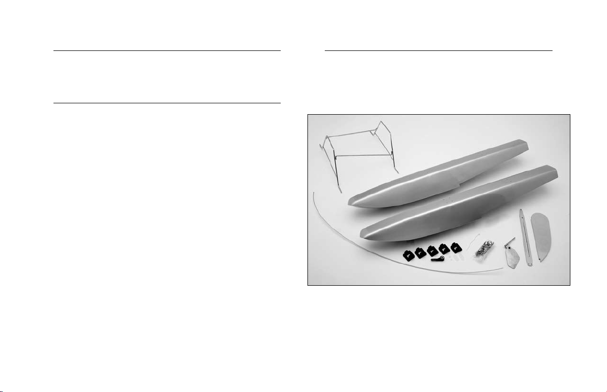
The floats have been constructed from high quality
fiberglass, have been painted with fuel-proof paint for
glow applications, and have the struts pre-welded for ease
of installation. The floats are ready to use out of the box
with only minor assembly required by the builder.
We hope you enjoy your float experience as much as
we have.
Tools Required
Phillips screwdriver
File or rotary tool
Hobby knife
Pliers
Drill
Drill bit: 5/64" (2mm)
Hex wrench: 1.5mm, 3/32"
2
Page 3
Adhesives Required
Replacement Parts
HAN8000 6-Minute Epoxy
Threadlock
Using the Manual
This manual is divided into sections to help make
assembly easier to understand, and to provide breaks
between each major section. In addition, check boxes
have been placed next to each step to keep track of each
step completed. Steps with a single circle () are performed
once, while steps with two circles ( ) indicate that the
step will require repeating, such as for a right or left wing
panel, two servos, etc.
Remember to take your time and follow the directions.
EFLA501 Wire Struts
EFLA502 Float A
ELFA503 Water Rudder
EFLA504 Hardware Package
EFLA505 Float B
Note: Both floats are identical in construction.
When reordering parts, Float B (EFLA505) has
the holes drilled on the stern for the rudder
assembly mount bracket. Float B (EFLA502)
does not have the holes pre-drilled.
3
Page 4

Limited Warranty Period
Horizon Hobby, Inc. guarantees this product to be free
from defects in both material and workmanship at the
date of purchase.
Limited Warranty & Limits of Liability
Pursuant to this Limited Warranty, Horizon Hobby, Inc. will,
at its option, (i) repair or (ii) replace, any product determined
by Horizon Hobby, Inc. to be defective. In the event of a
defect, these are your exclusive remedies.
product and will not cover consequential, incidental or
collateral damage. Horizon Hobby, Inc. reserves the right to
inspect any and all equipment involved in a warranty claim.
Repair or replacement decisions are at the sole discretion
of Horizon Hobby, Inc. Further, Horizon Hobby reserves the
right to change or modify this warranty without notice.
REPAIR OR REPLACEMENT AS PROVIDED UNDER
THIS WARRANTY IS THE EXCLUSIVE REMEDY OF
THE CONSUMER. HORIZON HOBBY, INC. SHALL
NOT BE LIABLE FOR ANY INCIDENTAL OR
CONSEQUENTIAL DAMAGES.
This warranty does not cover cosmetic damage or damage
due to acts of God, accident, misuse, abuse, negligence,
commercial use, or modification of or to any part of the
product. This warranty does not cover damage due to
improper installation, operation, maintenance, or attempted
repair by anyone other than an authorized Horizon Hobby,
Inc. service center. This warranty is limited to the original
purchaser and is not transferable. In no case shall Horizon
Hobby’s liability exceed the original cost of the purchased
4
As Horizon Hobby, Inc. has no control over use, setup,
final assembly, modification or misuse, no liability shall be
assumed nor accepted for any resulting damage or injury.
By the act of use, setup or assembly, the user accepts all
resulting liability.
If you as the purchaser or user are not prepared to accept
the liability associated with the use of this product, you
are advised to return this product immediately in new and
unused condition to the place of purchase.
Page 5

Safety Precautions
Questions or Assistance
This is a sophisticated hobby product and not a toy. It
must be operated with caution and common sense and
requires some basic mechanical ability. Failure to operate
this product in a safe and responsible manner could result
in injury or damage to the product or other property. This
product is not intended for use by children without direct
adult supervision.
The product manual contains instructions for safety,
operation and maintenance. It is essential to read and
follow all the instructions and warnings in the manual,
prior to assembly, setup or use, in order to operate
correctly and avoid damage or injury.
Questions, Assistance, and Repairs
Your local hobby store and/or place of purchase cannot
provide warranty support or repair. Once assembly, setup
or use of the product has been started, you must contact
Horizon Hobby, Inc. directly. This will enable Horizon to
better answer your questions and service you in the event
that you may need any assistance.
For questions or assistance, please direct your email to
productsupport@horizonhobby.com, or call 877.504.0233
toll free to speak to a service technician.
Inspection or Repairs
If your product needs to be inspected or repaired, please
call for a Return Merchandise Authorization (RMA). Pack
the product securely using a shipping carton. Please note
that original boxes may be included, but are not designed to
withstand the rigors of shipping without additional protection.
Ship via a carrier that provides tracking and insurance
for lost or damaged parcels, as Horizon Hobby, Inc. is not
responsible for merchandise until it arrives and is accepted
at our facility. Include your complete name, address, phone
number where you can be reached during business days,
RMA number, and a brief summary of the problem. Be sure
your name, address, and RMA number are clearly written on
the shipping carton.
5
Page 6

Warranty Inspection and Repairs
Non-Warranty Repairs
To receive warranty service, you must include your original
sales receipt verifying the proof-of-purchase date. Providing
warranty conditions have been met, your product will be
repaired or replaced free of charge. Repair or replacement
decisions are at the sole discretion of Horizon Hobby.
Should your repair not be covered by warranty and the
expense exceeds 50% of the retail purchase cost, you will
be provided with an estimate advising you of your options.
You will be billed for any return freight for non-warranty
repairs. Please advise us of your preferred method of
payment. Horizon Hobby accepts money orders and cashiers
checks, as well as Visa, MasterCard, American Express,
and Discover cards. If you choose to pay by credit card,
please include your credit card number and expiration date.
Any repair left unpaid or unclaimed after 90 days will be
considered abandoned and will be disposed of accordingly.
Electronics and engines requiring inspection or
repair should be shipped to the following address
(freight prepaid):
Horizon Service Center
4105 Fieldstone Road
Champaign, Illinois 61822
All other products requiring inspection or repair should
be shipped to the following address (freight prepaid):
Horizon Product Support
4105 Fieldstone Road
Champaign, Illinois 61822
6
Page 7
Float Installation (J-3 Cub)
Required Parts
• Fuselage • Landing gear
• Ventral fin mount • Ventral fin
• 3mm setscrew (4) • Hex wrench: 1.5mm
• Nylon bracket (4)
• 5/32" wheel collar (4)
• 3mm x 12mm sheet metal screw (16)
• 2mm x 12mm sheet metal screw (3)
• Nylon strap (2)
Required Tools and Adhesives
• Phillips screwdriver • File or rotary tool
• Threadlock • Hobby knife
• 6-minute epoxy
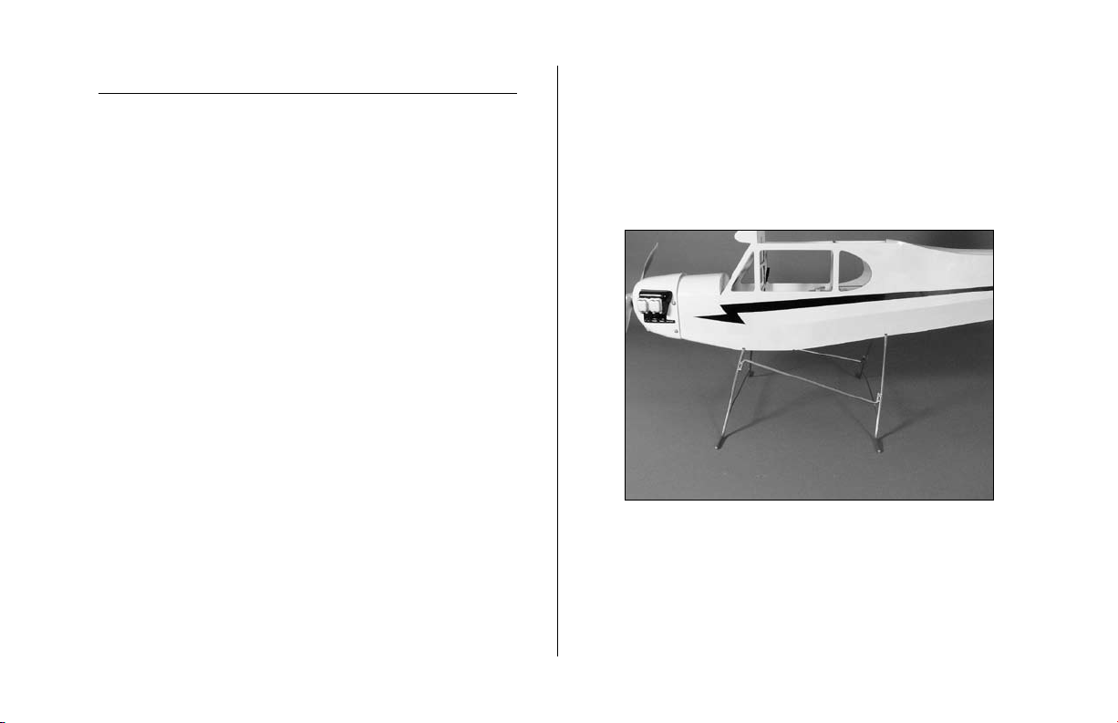
1. Remove the packing material from the landing
gear. Attach it to the fuselage using the two
nylon straps that were used to hold on the main
gear and the two nylon straps included with the
float kit. Use 2mm x 12mm screws to install the
nylon straps.
7
Page 8
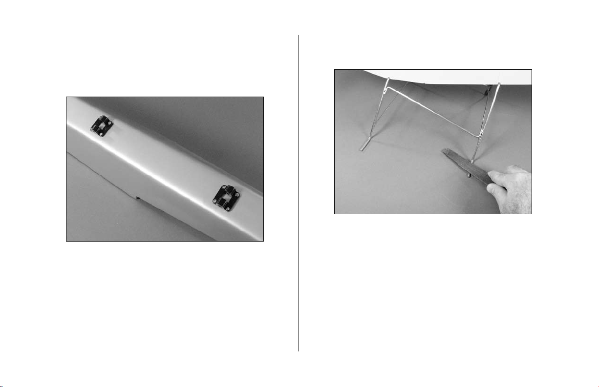
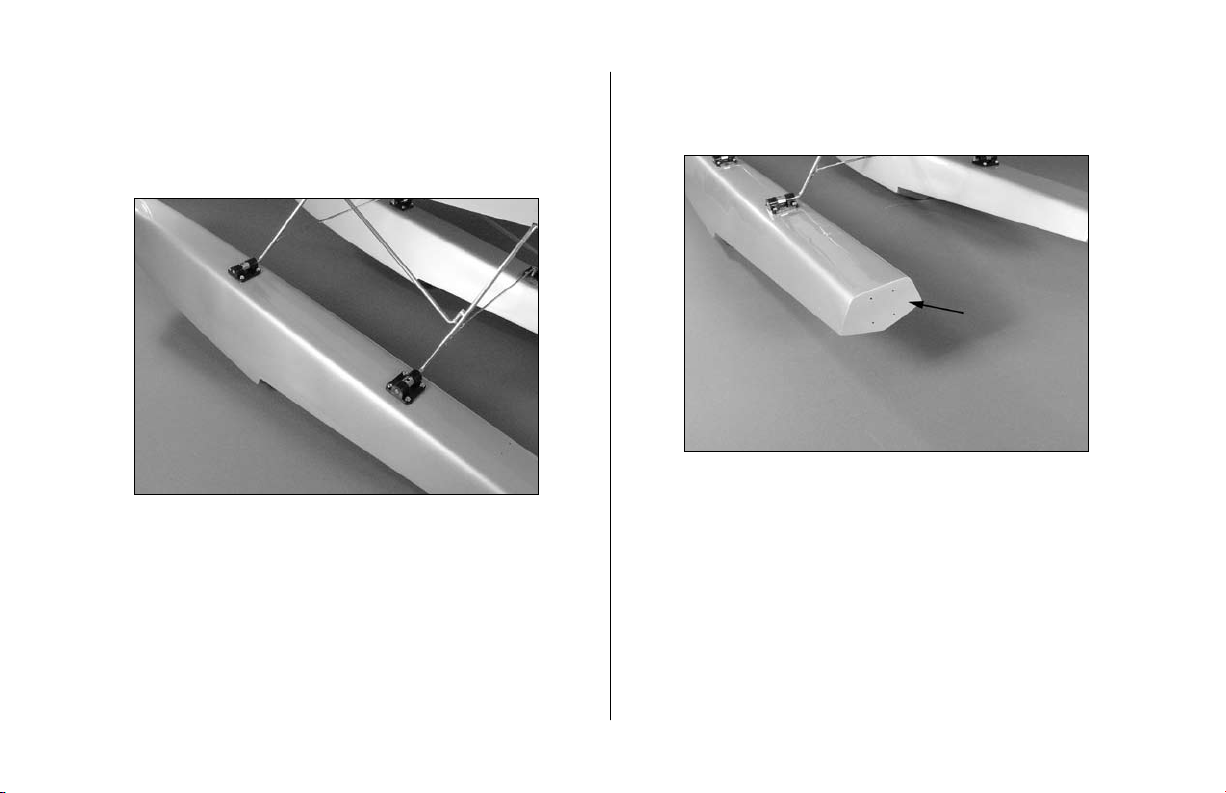
2. Attach two of the brackets to each float using
eight 3mm x 12mm sheet metal screws. Each
float uses two brackets, so you’ll install four
brackets in all.
3. Use a file or rotary tool to make a flat on the top
of each of the landing gear extensions.
8
Page 9
4. Attach the floats using the four 5/32" wheel
collars and four 3mm setscrews. Make sure to use
threadlock when tightening the setscrews onto the
flats made in the previous step.
Note: One float has holes drilled in the aft end
for the rudder bracket. This float is mounted on
the same side as the rudder linkage.
9
Page 10
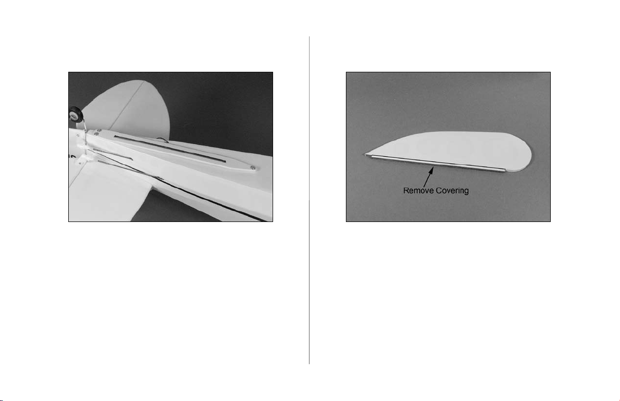
5. Attach the ventral fin mount using three 2mm x
12mm sheet metal screws.
6. Remove the bottom 1/8" (3mm) of covering from
the ventral fin using a hobby knife.
10
Page 11

7. Attach the ventral fin to the mount using 6-minute
epoxy. Make sure the fin is in line with the vertical
centerline of the fuselage.
Linkage Installation
Required Parts
• Fuselage w/floats • Nylon bracket
• Steering arm • 5/32" wheel collar
• 3mm setscrew (2) • Pushrod connector (2)
• Tie wrap • Half brass strap
• Full brass strap (3) • Connector backplate (2)
• Rudder shaft assembly
• 3mm x 12mm sheet metal screw (4)
3
• 29
/
" (755mm) pushrod cable
4
3
• 25
/
" (655mm) pushrod tube
• 2mm x 10mm sheet metal screw (7)
Required Tools and Adhesives
• Phillips screwdriver • Hobby knife
• Pliers • Threadlock
• Drill • Drill bit: 5/64" (2mm)
• Hex wrench: 1.5mm, 3/32”
4
11
Page 12

1. Attach a nylon bracket to the rear of the float
using four 3mm x 12mm sheet metal screws.
2. Place a 5/32" wheel collar in the center of the
nylon bracket. Slide the rudder assembly through
the nylon bracket and the wheel collar. Secure the
steering arm at the top and the wheel collar using
3mm setscrews.
Note: Remember to use threadlock on
both setscrews.
12
Page 13

3. Enlarge the middle hole in the steering arm
with a 5/64" (2mm) drill bit. Secure a pushrod
connector on the steering arm using a pushrod
connector backplate.
4. Enlarge the outboard hole in the rudder control
horn using a 5/64" (2mm) drill bit. Secure a
pushrod connector on the rudder horn using a
pushrod connector backplate.
13
Page 14

5. With the pushrod cable inside the pushrod tube,
attach the tube to the float using a full brass strap
and two 2mm x 10mm sheet metal screws. The
end of the pushrod tube is 1
the end of the float.
1
/
" (38mm) from
2
6. Use two full brass straps and the half brass strap
to attach the pushrod tube to the bottom of the
fuselage. Leave the straps slightly loose so it can
be moved around for the next step.
Note: These straps are secured onto the
crossbraces on the bottom of the fuselage.
14
Page 15

7. Use a tie wrap to attach the pushrod tube to the
landing gear. Slide the tube as necessary. Once
attached, go back and tighten the screws for the
brass straps.
8. With the rudder centered, secure the pushrod
cable using a 3mm setscrew. Place the steering
arm parallel with the end of the float and
secure the cable at the steering arm end using
a 3mm setscrew.
15
Page 16

9. Position the water rudder parallel to the rudder
of the aircraft. It may be necessary to loosen the
setscrew at the steering arm to do so.
10. Test the operation of the water rudder with the
aircraft rudder. The water rudder will move left
when the aircraft rudder moves left, and right
when the aircraft rudder moves right.
11. Adjust the water rudder to move up and down
by tightening or loosening the 4-40 socket
head screw on the rudder shaft. The water
rudder should be able to deflect up if it hits an
obstruction in the water.
12. Now that your floats have been installed, you
MUST verify that the Center of Gravity of your
model is still correct. Use the Center of Gravity
provided in the manual included with your
particular aircraft.
16
Page 17

Float Installation (Ultra Stick 25e)
Required Parts
• Fuselage • Landing gear
• 3mm setscrew (4)
• Nylon bracket (4)
• 4-40 x 1/2" socket head screw (3)
• 5/32" wheel collar (4)
• 3mm x 12mm sheet metal screw (16)
Required Tools and Adhesives
• Phillips screwdriver • File or rotary tool
• Threadlock • Hobby knife
• Hex wrench: 3/32"
Note: The Ultra Stick 25e comes with the
necessary landing gear mounts for the
installation of the floats. You will also find 4
molded 3.5mm spacer blocks in the Ultra Stick
25e kit which will be used when mounting the
float mounts onto the floats. Use these parts in
addition to the float hardware to complete the
installation.
1. Locate the holes on the fuselage for the rear
landing gear. These are located behind the air
exit on the fuselage. Use a hobby knife to
remove the covering. Attach the landing gear
to the fuselage using three 4-40 x 1/2" socket
head screws.
17
Page 18

2. Remove the wheels and wheel collars from the
main gear.
3. Attach two of the brackets and float mounts to
each float using eight 3mm x 12mm sheet metal
screws. Each float uses two brackets and two float
mounts, so you'll install eight pieces in all.
18
Page 19

4. Use a file or rotary tool to make a flat on the top
of each of the four axles.
5. Attach the floats using the four 5/32" wheel
collars and four 3mm setscrews. Make sure to use
threadlock when tightening the setscrews onto the
flats made in the previous step.
19
Page 20

Note: One float has holes drilled in the aft end
for the rudder bracket. This float is mounted on
the same side as the rudder linkage.
Linkage Installation
Required Parts
• Fuselage w/floats • Nylon bracket
• Steering arm • 5/32" wheel collar
• 3mm setscrew (4) • Pushrod connector (2)
• Rudder shaft assembly • Tie wrap
• Full brass strap (3) • Connector backplate (2)
• 3mm x 12mm sheet metal screw (4)
3
• 29
/
" (755mm) pushrod cable
4
3
• 25
/
" (655mm) pushrod tube
• 2mm x 10mm sheet metal screw (6)
Required Tools and Adhesives
• Phillips screwdriver • Hobby knife
• Pliers • Threadlock
• Drill • Drill bit: 5/64" (2mm)
• Hex wrench: 1.5mm, 3/32”
4
20
Page 21

1. Attach a nylon bracket to the rear of the float
using four 3mm x 12mm sheet metal screws.
2. Place a 5/32" wheel collar in the center of the
nylon bracket. Slide the rudder assembly through
the nylon bracket and the wheel collar. Secure the
steering arm at the top and the wheel collar using
3mm setscrews.
Note: Remember to use threadlock on
both setscrews.
21
Page 22

3. Enlarge the middle hole in the steering arm
with a 5/64" (2mm) drill bit. Secure a pushrod
connector on the steering arm using a pushrod
connector backplate.
4. Enlarge the outboard hole in the rudder control
horn using a 5/64" (2mm) drill bit. Secure a
pushrod connector on the rudder horn using a
pushrod connector backplate.
22
Page 23

5. With the pushrod cable inside the pushrod tube,
attach the tube to the float using a full brass strap
and two 2mm x 10mm sheet metal screws. The
end of the pushrod tube is 1
end of the float.
1
/
" (38mm) from the
2
6. Bend two full brass straps to attach the pushrod
tube to the top of the fuselage. Leave the straps
slightly loose so it can be moved around for the
next step.
23
Page 24

7. Use a tie wrap to attach the pushrod tube to the
landing gear. Slide the tube as necessary. Once
attached, go back and tighten the screws for the
brass straps.
8. With the rudder centered, secure the pushrod
cable using a 3mm setscrew. Place the steering
arm parallel with the end of the float and
secure the cable at the steering arm end using
a 3mm setscrew.
24
Page 25

9. Position the water rudder parallel to the rudder
of the aircraft. It may be necessary to loosen the
setscrew at the steering arm to do so.
10. Test the operation of the water rudder with the
aircraft rudder. The water rudder will move left
when the aircraft rudder moves left, and right
when the aircraft rudder moves right.
11. Adjust the water rudder to move up and down
by tightening or loosening the 4-40 socket
head screw on the rudder shaft. The water
rudder should be able to deflect up if it hits an
obstruction in the water.
12. Now that your floats have been installed, you
MUST verify that the Center of Gravity of your
model is still correct. Use the Center of Gravity
provided in the manual included with your
particular aircraft.
25
Page 26

Float Flying
Flying from floats can be great fun. There are a few things
to remember when you hit the lake. First, make sure you
pick a location where you can take off and land parallel
to the shore line with no obstructions. You will want to
make sure you are taking off and landing into the wind.
Verify your water rudder is down and the plane is
powered up. Set the plane into the water and begin to
taxi out. It is common to hold full up elevator (back stick)
during all taxi maneuvers. This helps to eliminate prop
splash and keeps the water rudder deep in the water for
improved steering. You may want to use a high rate for
your rudder during this operations as well. You will switch
to a low rate rudder for takeoff.
Taxi slow to get the hang of the rudder. Once you have
lined up for takeoff, set your rudder dual rate to low. The
water rudder becomes very effective during takeoff. Apply
full up elevator and apply throttle slowly at first. As the
plane picks up speed, you will notice it coming up on step.
At this time, you can relax the elevator input and fly off
the water the same way you take off from hard ground.
Once in the air, you will find the plane to behave slightly
different that before. The added weight below the model
acts similar to a pendulum effect in flight. It will slightly
effect the aerobatic performance as well. You will notice a
higher power setting from normal due to the added drag
and weight of the floats.
26
Page 27

Float Flying
Landing on water is very similar to landing on hard
ground. Set up like you normally would and turn onto
final approach. Maintain power during the approach,
as a plane with floats tends to land slightly faster than
when equipped with landing gear. As you come down,
begin to flair and hold it until touchdown. Once you
have touched down on the water, as the plane slows
down, begin to feed in up elevator as the plane settles.
Once you are slowed down, taxi back to shore and get
ready for another day at the lake.
Please refer to the instruction manual for the J-3 Cub or
Ultra Stick 25e for further information on flying with floats.
We hope you enjoy flying off water as much as we do.
Happy Float Flying.
27
Page 28

2006 Official AMA National Model Aircraft Safety Code
GENERAL
1) I will not fly my model aircraft in sanctioned events,
air shows or model flying demonstrations until it
has been proven to be airworthy by having been
previously, successfully flight tested.
2) I will not fly my model higher than approximately
400 feet within 3 miles of an airport without notifying
the airport operator. I will give right-of-way and avoid
flying in the proximity of full-scale aircraft. Where
necessary, an observer shall be utilized to supervise
flying to avoid having models fly in the proximity of
full-scale aircraft.
3) Where established, I will abide by the safety rules
for the flying site I use, and I will not willfully or
deliberately fly my models in a careless, reckless and/
or dangerous manner.
4) The maximum takeoff weight of a model is 55
pounds, except models flown under Experimental
Aircraft rules.
5) I will not fly my model unless it is identified with
my name and address or AMA number on or in the
model. (This does not apply to models while being
flown indoors.)
6) I will not operate models with metal-bladed
propellers or with gaseous boosts, in which gases
other than air enter their internal combustion
engine(s); nor will I operate models with extremely
hazardous fuels such as those containing
tetranitromethane or hydrazine.
RADIO CONTROL
1) I will have completed a successful radio equipment
ground range check before the first flight of a new or
repaired model.
2) I will not fly my model aircraft in the presence
of spectators until I become a qualified flier, unless
assisted by an experienced helper.
28
Page 29

2006 Official AMA National Model Aircraft Safety Code
3) At all flying sites a straight or curved line(s) must
be established in front of which all flying takes place
with the other side for spectators. Only personnel
involved with flying the aircraft are allowed at or in
front of the flight line. Intentional flying behind the
flight line is prohibited.
4) I will operate my model using only radio control
frequencies currently allowed by the Federal
Communications Commission. (Only properly licensed
Amateurs are authorized to operate equipment on
Amateur Band frequencies.)
5) Flying sites separated by three miles or more
are considered safe from site-to-site interference,
even when both sites use the same frequencies. Any
circumstances under three miles separation require a
frequency management arrangement, which may be
either an allocation of specific frequencies for each site
or testing to determine that freedom from interference
exists. Allocation plans or interference test reports shall
be signed by the parties involved and provided to
AMA Headquarters.
Documents of agreement and reports may exist
between (1) two or more AMA Chartered Clubs,
(2) AMA clubs and individual AMA members not
associated with AMA Clubs, or (3) two or more
individual AMA members.
6) For Combat, distance between combat engagement
line and spectator line will be 500 feet per cubic inch
of engine displacement. (Example: .40 engine = 200
feet.); electric motors will be based on equivalent
combustion engine size. Additional safety requirements
will be per the RC Combat section of the current
Competition Regulations.
7) At air shows or model flying demonstrations, a
single straight line must be established, one side of
which is for flying, with the other side for spectators.
8) With the exception of events flown under AMA
Competition rules, after launch, except for pilots or
helpers being used, no powered model may be flown
closer than 25 feet to any person.
9) Under no circumstances may a pilot or other person
touch a powered model in flight.
29
Page 30

Notes
30
Page 31

Notes
31
Page 32

8688
© 2006 Horizon Hobby, Inc.
4105 Fieldstone Road
Champaign, Illinois 61822
(877) 504-0233
horizonhobby.com
E-fliteRC.com
 Loading...