

Effekta MKD 700 RT XL, MKD 1500 RT, MKD 1000 RT XL, MKD 1500 RT XL, MKD 1000 RT Operating Manual
...
UPS
Uninterruptable Power Supply
MKD 700 – 3000 VA RT (XL)
Operating Manual V 2.6
Device: Article number:
MKD 700 RT ACX11MKT70000000
MKD 1000 RT ACX11MKT1K000000
MKD 1500 RT ACX11MKT1K500000
MKD 2000 RT ACX11MKT2K000000
MKD 3000 RT ACX11MKT3K000000
MKD 700 RT XL ACX11MKT70000RXL
MKD 1000 RT XL ACX11MKT1K000RXL
MKD 1500 RT XL ACX11MKT1K500RXL
MKD 2000 RT XL ACX11MKT2K000RXL
MKD 3000 RT XL ACX11MKT3K000RXL
Translation of original operating manual

UPS: MKD 700 – 3000 VA RT (XL) Legal Notice
Legal Notice
by EFFEKTA Regeltechnik GmbH
This documentation is solely intended for the operator and his staff. The content
of this documentation (texts, figures, drawings, graphics, plans, etc.) may not be
copied or distributed in part or in full without our written consent, nor can it be
used without authorization for competitive purposes or given made accessible to
third parties.
The publication and copyright of this documentation are retained by:
EFFEKTA Regeltechnik GmbH
Rheinwaldstraße 34
78628 Rottweil, Germany
Telephone: + 49 (0) 741 17451 - 0
Telefax: + 49 (0) 741 17451 - 22
Email: ups@effekta.com
Internet: www.effekta.com
Operating Manual: V 2.6
Language: English
Date of issue: 07/2016
We reserve the right to make changes to the design and the system that will
improve the system, the production process or the product.

UPS: MKD 700 – 3000 VA RT (XL) Table of Contents
Table of Contents
1. Introduction ............................................................................................................. 5
1.1 Preface ...................................................................................................................... 5
1.2 Validity ....................................................................................................................... 6
1.3 Storage ...................................................................................................................... 6
1.4 Abbreviations, terms and symbols ............................................................................. 6
1.5 Information obligation ................................................................................................ 9
1.6 Warranty conditions ................................................................................................. 10
1.7 Limitation of liability.................................................................................................. 11
2. Safety instructions ................................................................................................ 12
2.1 Introduction .............................................................................................................. 12
2.2 Proper use ............................................................................................................... 12
2.3 Prevention of personal injury / property damage ...................................................... 13
2.4 Environmental protection ......................................................................................... 13
2.5 Transport and storage ............................................................................................. 13
2.6 Positioning ............................................................................................................... 14
2.7 Connection .............................................................................................................. 14
2.8 Operation................................................................................................................. 16
2.9 Working with accumulators ...................................................................................... 16
2.10 Maintenance, service and malfunctions ................................................................... 17
3. UPS device description ......................................................................................... 18
3.1 Topology and operating modes ................................................................................ 18
3.2 The device series, format and housing sizes ........................................................... 22
3.3 The device components and connection areas ........................................................ 23
4. Storage and unpacking ......................................................................................... 31
4.1 Storage of the UPS .................................................................................................. 31
4.2 Transport to the installation site ............................................................................... 31
4.3 Unpacking and positioning the UPS ................................ ......................................... 32
5. Installation and connection of the UPS ................................................................ 34
5.1 Installation in 19“ cabinet (RACK) ............................................................................ 34
5.2 Installation as a standing device (TOWER) .............................................................. 39
5.3 Preparations for connection ..................................................................................... 41
5.4 Connecting the UPS device ..................................................................................... 43
6. Operation of device and service ........................................................................... 51
6.1 Operation and performance of the UPS ................................................................... 51
6.2 Menu navigation, settings and commands ............................................................... 55

UPS: MKD 700 – 3000 VA RT (XL) Table of Contents
7. Initial operation of the UPS ................................................................................... 67
8. Messages, error codes and corrective actions .................................................... 69
8.1 Messages for specific operating modes: .................................................................. 69
8.2 Error messages on the UPS: ................................................................................... 69
9. Troubleshooting .................................................................................................... 72
10. Service Hotline ....................................................................................................... 72
11. Software ................................................................................................................. 73
12. Maintenance and Service ...................................................................................... 74
12.1 Measuring the support time (autonomous time) ....................................................... 74
12.2 Replacing components / accumulators .................................................................... 75
12.3 Maintenance and service contracts .......................................................................... 75
12.4 Service log ............................................................................................................... 76
13. Technical data ........................................................................................................ 77
13.1 Typical autonomous times ....................................................................................... 78
13.2 Load-bearing capacity of the internal interface (DRY CONTACT) ............................ 78
14. Scope of delivery / accessories ............................................................................ 79
15. Optional accessories ............................................................................................. 80
15.1 Communications adapter: Relay card (AS400) ....................................................... 80
15.2 Communication adapter SNMP ................................................................................ 81
15.3 External by-pass ...................................................................................................... 81
15.4 External battery bank ............................................................................................... 82
16. Wear parts .............................................................................................................. 83
17. Declaration of conformity ..................................................................................... 83

UPS: MKD 700 – 3000 VA RT (XL) Introduction
1. Introduction
1.1 Preface
Dear Operator,
This manual is required for the operation of the uninterruptible power supply
described herein.
This operating manual should provide you with support for working
responsibly and give basic information about the uninterruptible power supply,
namely on how it works, its application and, in addition, what you should do in
the event of malfunctioning. Furthermore, this operating manual contains
instructions for the transport and storage as well as for the handling and
installation of the uninterruptible power supply.
The planning guidelines in this operating manual only relate to special
requirements and characteristics of the uninterruptible power supply. All
national and local provisions and regulations for electrical installations have to
be adhered to in the installation process. The same applies to the operation of
the device.
The content of this operating manual may change due to technological
progress. We have done our best to present the content correctly and clearly.
If, however, we have made errors, we would be grateful if you would let us
know.
We do not assume any liability for errors in this operating manual or any
consequences resulting thereof.
The uninterruptible power supply is intended to protect sensitive electronic
systems and equipment from interferences that could occur due to poor
electric quality or network failures.
Please read this operating manual carefully and take note particular note of
the safety instructions!
If you have questions about the device, the technical supervisor at your
company or our employees will gladly assist you.
Your
EFFEKTA Regeltechnik GmbH
UPS: MKD 700 – 3000 VA RT (XL) Introduction
1.2 Validity
The descriptions in this operating manual relate solely to the uninterruptible
power supply (UPS) defined in the technical data as a whole or as it refers to
modules, components and individual parts that were developed and built by
EFFEKTA Regeltechnik GmbH ( Chapter 13. Technical data).
Read this documentation carefully and familiarize yourself with the product
before you begin operating it.
1.3 Storage
The operating manual for the device must be stored in the vicinity of the
device at all times so it is immediately available if need be.
Pass this manual on to any subsequent users of the product.
1.4 Abbreviations, terms and symbols
In this manual, the abbreviation UPS stands for: uninterruptible power supply.
Typically, accumulators are used as energy storage of the UPS-equipment.
Colloquially, these are referred to as batteries or rechargeable batteries. A
battery bank is then the term for the centralization of several accumulators
into a group that forms the energy storage.
Danger, Warning, and Attention references are explicitly marked by the
respective symbols (pictograms) and must be adhered to without fail. See the
following list and explanations:
Danger / Warning levels / Notes:
Text marked with DANGER! provides a warning about dangers. If accident
prevention measures are not taken, these dangers result in serious
(irreversible) injuries or even death!
UPS: MKD 700 – 3000 VA RT (XL) Introduction
Text marked with WARNING! provides a warning about hazards. If accident
prevention measures are not taken, these hazards may result in serious
(irreversible) injuries or even death!
Text marked with CAUTION! provides a warning about hazards. If accident
prevention measures are not taken, these dangerous situations can lead to
slight or medium reversible injuries.
Text marked with ATTENTION! contains very important instructions for
situations that, if accident prevention measures are not taken, may result in
damage to the product and / or its functions or an object in its vicinity.
This Symbol indicates text that contains notices or instructions / comments or
hints.
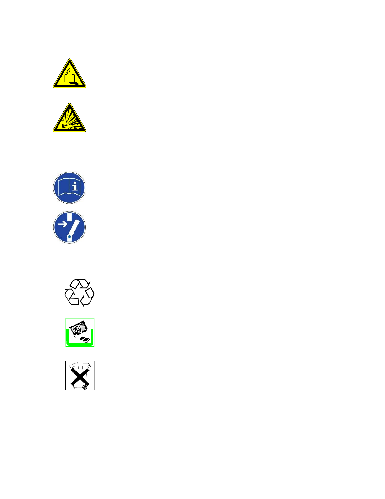
Warning about danger areas:
General warning about danger areas!
Specific warnings:
Warning about dangerous electrical voltage!
UPS: MKD 700 – 3000 VA RT (XL) Introduction
Warning about proper handling of accumulators!
Warning about handling explosive materials!
Instruction symbols:
Take note of the provided documentation and/or instructions!
Disconnect before working!
Environmental symbols:
Indentifies instructions for recycling.
Identifies components that are subject to the Electronic Scrap Regulation.
Identifies components or parts that must be disposed of properly. Do not throw
these into the household waste.

UPS: MKD 700 – 3000 VA RT (XL) Introduction
Text symbols:
●
This dot indicates descriptions of activities that you should carry out.
A requirement that must be fulfilled, for example:
The DC circuit breaker is “OFF”.
–
This dash marks specification lists.
This arrow marks a cross reference.
If a cross reference to another chapter is necessary in the text, this is
shortened for clarity.
Example: OM, 2 Safety Instructions
This means: see Operating Manual,
Chapter 2 Safety Instructions.
If the cross reference refers to a page, figure or position number, this
information is added at the end of the cross reference.
Example: Fig. 4-4, Pos. 1
This means: see (in this manual in Chapter 4) in
Figure 4, the position number 1.
(3)
Numbers in brackets refer to the positions in the figures.
**
Annotations within the text are marked with ** and explained accordingly.
1.5 Information obligation
This operating manual must be read and understood by all persons and
qualified personnel working with this device (this equipment).
This applies, in particular, to maintenance, operating and cleaning personnel
including persons responsible for transportation and/or disposal.
EFFEKTA Regeltechnik GmbH is not liable for damage incurred or caused by
staff who have not been trained or who have been insufficiently trained!

UPS: MKD 700 – 3000 VA RT (XL) Introduction
1.6 Warranty conditions
The receipt of delivery is considered to be the record for the initial purchase
and should be kept in a safe place. It will be necessary for making use of the
warranty. If the product is passed on to another user, this user has the right to
the warranty for the remainder of the warranty period. The purchase receipt
as well as this declaration should also be given to the new owner if the device
is passed on.
We guarantee that this device, upon delivery, is in a functional state and
technically conforms to the descriptions in the enclosed documentation.
The warranty period for UPS devices corresponds to the minimum periods
stipulated by law.
The warranty ceases to apply in the following cases:
– if the defect is caused by: freight damage, accident, natural
disasters, misuse, vandalism;
– in case of improper use, defective maintenance or incorrect repair
by third parties;
– in the event of changes, unauthorized intervention, improper
operation, false installation or other modifications not approved by
us;
– in the case of improper use such as the connection of the device
to unsuitable energy sources or unsuitable loads, or in general use
in an unsuitable environment, etc.;
– in the event of failure to follow instructions in the provided
documentation;
– for any defects caused by a lack of due care, e.g. splash water,
etc.;
– in the event that the product is incompatible due to possible
technical innovations or regulations (policies) that occur after the
purchase;
– in the case of malfunctions or damage caused by the connection
to incompatible devices or accessories;
– in the event of developments that are related to the normal ageing
process of the product (wear parts); e.g., shortened life span due
to batteries at increased (higher than 25°C) ambient temperature.
– in the event of defects that were caused by external fixtures, e.g.
electrical outlets;
– in the event of failure to provide due maintenance and care for the
product;

UPS: MKD 700 – 3000 VA RT (XL) Introduction
The warranty period for replaced and/or repaired parts as part of this warranty
expires together with the original warranty for the product.
Devices that are supplied without accessories are replaced without
accessories. The return of the device is only accepted if it is sent in the
original packaging.
Incurred transport costs are generally not included in the warranty.
In general, you shall bear the cost of repair and exchange of the device.
We are not liable for damage or consequential damage, whether directly,
unintentionally or caused by negligence.
EFFEKTA Regeltechnik GmbH does not provide either explicit or implicit
warranties related to this device and its quality, performance, salability or
suitability for a certain purpose. In some countries, the exclusion of implicit
warranties is not permitted by law. In this case, the validity of all explicit and
implicit warranties is limited to the warranty period. With the expiration of
these periods, all warranties lose their validity. In some countries, a limitation
of the validity period of implicit warranties is not permitted by law so that the
aforementioned limitation does not take effect.
1.7 Limitation of liability
Claims to damage compensation are excluded unless they involve intent or
gross negligence by EFFEKTA Regeltechnik GmbH or its employees. This
does not affect liability according to the Product Liability Act. Under no
circumstances are we liable for:
– Claims that third parties make against you due to losses or
damage;
– Loss or damage of your records or data or the costs of recovering
this data;
– Subsequent economic damage (including lost profits or savings) or
concomitant damage, even in the event that we were informed of
the possibility of such damage.
Under no circumstances is EFFEKTA Regeltechnik GmbH responsible for
any accidental, indirect, specific, consequential or other damage of any kind
(including, without any limitation, damage related to a loss of profits,
interruption of business, loss of business information, or any other losses)
that result from the use of the device or are connected with the device
whether they are based on the contract, damage compensation, negligence,
strict liability or other claims, even if EFFEKTA Regeltechnik GmbH was
informed about the possibility of such damage in advance. This exemption
also includes any liability that can result from the claims of third parties
against the initial purchaser.

UPS: MKD 700 – 3000 VA RT (XL) Introduction
In some countries, the exemption or the limitation of concomitant
consequential damage is not permitted by law so that the aforementioned
declaration does not enter into force.
2. Safety instructions
2.1 Introduction
The UPS is a device that has been produced according to the rules and
regulations of technology for an uninterruptible power supply.
The device is safe when used properly and under consideration of the safety
requirements and instructions provided in this operating manual.
2.2 Proper use
The UPS and its related components may only be used for purposes in
accordance with its design – to provide a primary energy source for electrical
devices and a short-term supply from a secondary energy source for electrical
devices which does not exceed the nominal power in its entirety. Any other use
is considered improper and can lead to injury of person or property and/or
damage to the device!
The device is not designed for use
– in explosive;
– in dusty or humid;
– in radioactive or;
– in biologically or chemically contaminated atmospheres!
For information about the respective IP protection class of the device please
contact our service centers.
In addition, the device class must be noted with regard to “electromagnetic
compatibility” (EMC). For this, see the standard DIN EN 62040-2.
The UPS is a Class C2 or C3 device. Take note of the information about the
device class in the provided specifications (13 Technical dat). UPS systems

UPS: MKD 700 – 3000 VA RT (XL) Introduction
intended for the so-called “second setting” belong to this class. These UPS
systems are appropriate for use in commercial or industrial facilities with a
minimum distance of 10 m (C2) or 30 m (C3) from other buildings that belong to
the “first setting.”
In brief: This device can cause radio interference in residential areas. In this
case, the operating company may be requested to take appropriate measures!
2.3 Prevention of personal injury / property damage
– Please read this operating manual carefully to familiarize yourself
with the device. Under no circumstances should you ignore the
safety information.
– Pay particular attention during the installation and initial operation of
the device.
– Operate this product only in the proper and appropriate manner and
always within the mandated performance parameters (13
Technical Data).
– Only perform maintenance and service work that is described in the
documentation. Observe the required steps. Only use original
replacement parts from EFFEKTA Regeltechnik GmbH.
2.4 Environmental protection
Send the product back to EFFEKTA Regeltechnik GmbH after the end of its
service life. We will ensure its environmentally friendly disposal.
2.5 Transport and storage
The UPS may only be transported to the intended location in the original packaging. The same applies to moves or returns.
The packaging has a very good device-specific protective function. However, all
devices damaged during transport must be checked by EFFEKTA Regeltechnik
GmbH before the initial operation. The same generally applies for any damages
to the device.
Should the device be in storage for more than 4 months, the battery bank of the
UPS device must be charged urgently. For more, see 4.1 Storage of the
UPS.
UPS: MKD 700 – 3000 VA RT (XL) Introduction
Due to the possibility of existing energy storage (accumulators) within a UPS,
devices must generally be inspected by EFFEKTA Regeltechnik GmbH or a
qualified service center after transportation damages. In the case of
transportation damages, there is a high risk that the energy storage units and/or
their electrical connections have been affected. As a result, short circuits and/or
the leaking of electrolytes cannot be ruled out. For this reason, the unit must be
isolated until an inspection has been performed.
In addition, the device should not be transported or stored upside-down.
2.6 Positioning
Only operate the UPS in well-ventilated rooms, ensuring the specified ambient
temperature range (according to 13 Technical dat).
The UPS should not be placed in the vicinity of heat sources. In the event of
increased ambient temperature (higher than 25°C), the life span of the battery
will decrease considerably; as a result, the battery’s warranty will be terminated.
Always take the operating conditions into account when positioning the device.
Maintain the minimum distance to adjacent equipment and walls necessary for
ventilation purposes (see 13 Technical dat and 5 Installation and
connection of the UPS ensure that the necessary air circulation is provided.
Never place or operate the device in a moist environment. Liquids must, as a
rule, be kept away from the device.
Due to major temperature differences, condensation or dew effects may occur
after the positioning of the UPS. Therefore, an acclimatization period of at least
two hours must be observed before any further steps are taken. Make sure the
temperature adjustment has been completed and that any surfaces with
condensation inside and outside the device have completely dried.
Never operate the UPS in an explosive and/or unventilated setting.
2.7 Connection
Always use the connection terminals or blocks provided for the purpose of
connecting the UPS.
UPS: MKD 700 – 3000 VA RT (XL) Introduction
To avoid electrical hazards, the connection of the unit must only be made under
de-energized conditions.
The PE (protective earth) conductor must be connected without fail. The UPSdevice, as well as the connected loads, must not be used without the PE
conductor under any circumstances!
The UPS output is supplied with power even in the event of a power outage;
according to the provisions included in EN62040-1, the lines and power outlets
supplied by the UPS must be clearly labelled!
In addition, the following points must always be followed when connecting the
UPS:
– Install all connections appropriately and keep the cable length as
short as possible;
– Only use suitable power cables when connecting the UPS to the
mains power supply and pay attention to the required current
carrying capacity;
– Only use suitable power cables when connecting appliances to the
UPS and pay attention to the required current carrying capacity;
– The safeguarding of any appliance must always be performed
immediately in front of an appliance and may never be performed
centrally in front of the UPS;
– Never operate any household devices or tools such as e. g. fan
heaters, vacuum cleaners, electric drills, hairdryers, toasters, etc. by
means of the UPS;
– Do not connect any appliance to the UPS that could overload the
device;
– In general, only use appropriate tools for the installation.
2.7.1 EPO, Emergency Power Off for loads
Should an emergency power-off circuit “EPO” or “REPO” (REMOTE
EMERGENCY POWER OFF) be installed, this control circuit must
unconditionally be separated from all other electrical circuits by reinforced
insulation.
UPS: MKD 700 – 3000 VA RT (XL) Introduction
The purpose of an EPO connection is for emergency power off and the
release of the loads.
2.8 Operation
Only qualified personnel are permitted to access and operate the device.
In all situations, it must be kept in mind that the UPS includes an energy storage
or is connected to an external energy storage unit. This means that the UPS
outlet can be current-carrying even when the UPS has already been
disconnected from the mains power supply.
Consequently, the UPS output is guaranteed to be de-energized only when the
device has completely shut down and has been disconnected from the mains
power supply.
2.9 Working with accumulators
When handling accumulators, there is always a risk of electric shock, burns
and/or chemical burns.
For this reason, unauthorized personnel should not have access to
accumulators.
Accumulators or their current points can cause electric shock.
In the event of a short-circuit of the accumulators, touching the current-carrying
parts can result in severe burns.
Do not place accumulators in the vicinity of heat sources and do not bring them
into contact with open fire. Explosion hazard!
Accumulators should never be opened or destroyed. The electrolyte released
presents a great danger to your health and the environment. It could result in
chemical burns to skin and eyes; moreover, the electrolyte is very toxic.

UPS: MKD 700 – 3000 VA RT (XL) Introduction
Defective accumulators must be disposed of in an environmentally friendly
manner!
Never dispose of accumulators with regular household waste!
Local disposal regulations must be observed!
2.10 Maintenance, service and malfunctions
Attention – risk of electric shock.
Even after switching off the supply with the power button or after disconnecting
the accumulator feed, parts of the UPS can still carry high voltages.
The following precautions must be taken when working on the UPS and the
accumulators:
– Before beginning work on the UPS, it must first be switched off and
disconnected from the mains power supply and the loads.
– Remove wristwatches, jewelry and other metallic objects;
– Use only isolated tools;
– Work on live equipment must only be performed by specially trained
personnel. These persons must wear the appropriate personal
protective equipment (PPE) at all times;
– The UPS may not be disassembled;
– Work on the accumulators must only be carried out and supervised
by personnel with the required expertise concerning safety
regulations;
– Unauthorized personnel are to be kept away from the UPS and the
accumulators.
UPS: MKD 700 – 3000 VA RT (XL) UPS Device Description
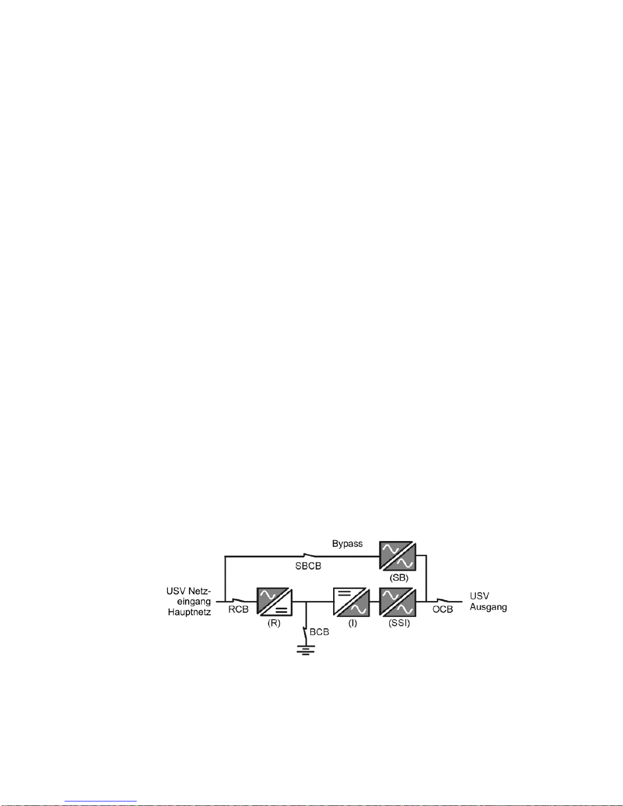
3. UPS device description
This UPS device is an ONLINE UPS after the double conversion principle.
Based on the outstanding performance according to EN 62040-3, the UPS
receives “Class 1” (VFI-SS-111) classification. This way subsequently
connected appliances will be optimally provided for, irrespective of how a
primary source of power (mains power supply) performs.
Malfunctions such as: mains power failure, power supply undervoltage, power
supply overvoltage, temporary mains voltage changes (transients), subtle mains
power deviations, frequency changes, etc. will not be transferred to the
connected loads in standard operating mode.
The UPS is used to support sensitive devices and facilities such as, e.g.:
computers, servers, emergency systems, electronic cash registers, instruments
critical to operation critical, telecommunication facilities, processor control
systems, surveillance and management systems, etc.
A conversion to autonomous time follows by way of the adaption of an external
battery bank or its capacity.
3.1 Topology and operating modes
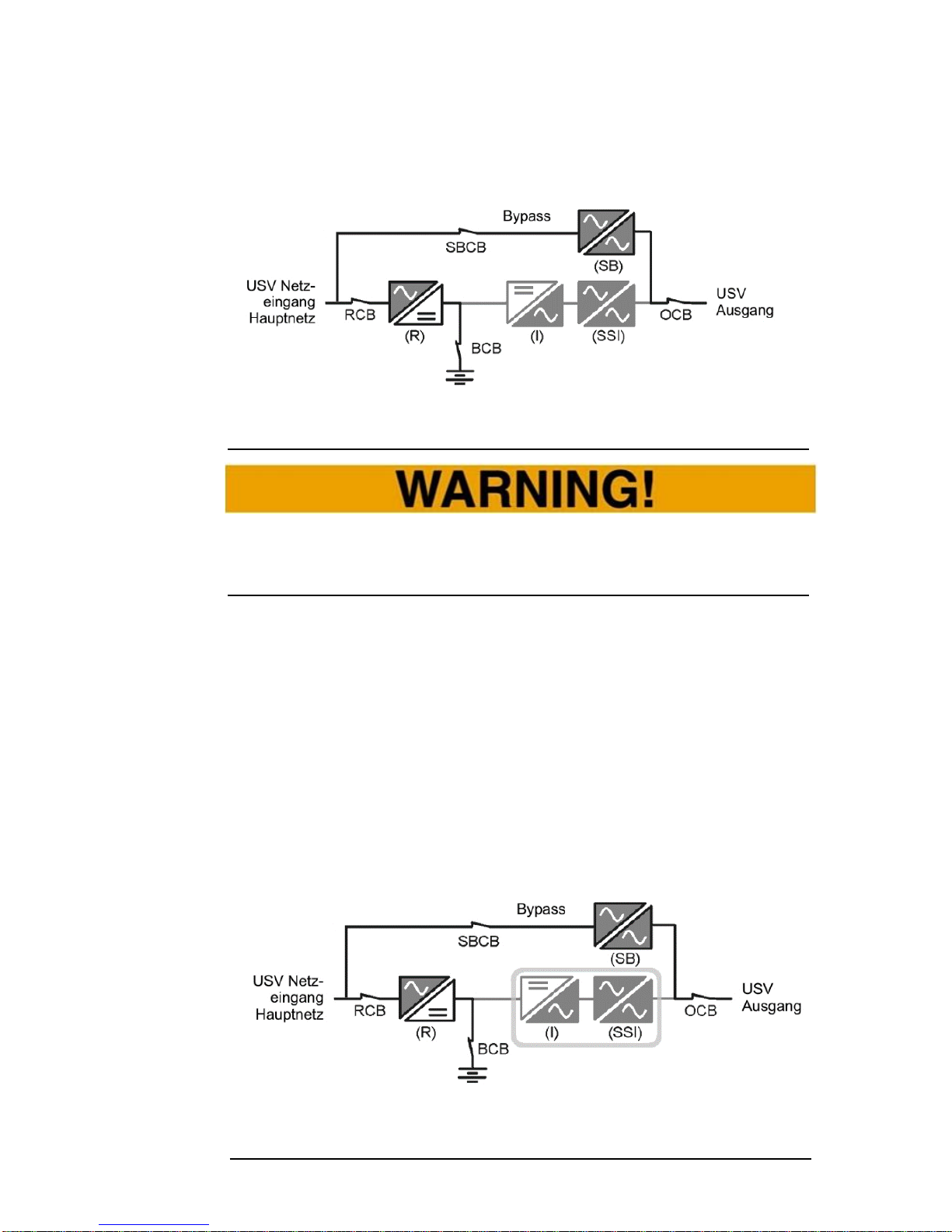
The following figure (
Fig. 3-1), a block diagram of the UPS device, clearly shows the double
conversion principle. The mains power supply is converted to the DC
intermediate circuit whereby the energy storage (battery bank) is charged. The
loads, or appliances, on the UPS output are fed without failures or interruptions
by an additional conversion (INVERTER).
Fig. 3-1 Topology, function groups for the UPS device.
It is clear that, within the mains power supply, failures do not reach the UPS
output and, consequently, the load. Furthermore, all operation modes of the
UPS device can be derived from and represented by the above mentioned block
diagram:

UPS: MKD 700 – 3000 VA RT (XL) UPS Device Description
Standard operation mode (INVERTER MODE)
The standard operation mode is characterized here by a classic double
conversion. The supply network is converted to the DC intermediate circuit
which then feeds the UPS output through an inverter (DC/AC converter). The
by-pass is inactive here.
.
Fig. 3-2 Operating mode: standard operation.
Support or autonomous mode (BATTERY MODE)
In the event the supply network temporarily fails, the inverter draws power
directly from the battery bank and thereby supplies the UPS output without
interruption. The autonomous mode is limited by the capacity of the battery bank
and its charging status.
Fig. 3-3 Operating mode: autonomous mode.
Static by-pass operation mode (FAULT MODE)
Often in the case of a device fault (fault mode) with the inverter, the UPS
automatically and without interruption of the UPS output switches to the static
by-pass operation mode. In doing so, the load feed is securely maintained over
the power supply, albeit without the support function of the UPS. Once the fault
UPS: MKD 700 – 3000 VA RT (XL) UPS Device Description
has been eliminated, the device returns to normal operation mode. Malfunctions
can also be caused by the loads such as when the UPS is overloaded.
Fig. 3-4 Operating mode: static by-pass.
Never leave the UPS in the static by-pass mode, or the fault mode, for a long
period of time. The loads will continue to be supplied yet without any support
function from the UPS.
The static by-pass mode can also be intentionally switched on, e.g. for
screening.
Power saving mode (ECO MODE)
The “power-saving mode,” called ECO MODE, is a feature of the MKD series.
The UPS device is intentionally operated in the static by-pass mode for this
purpose. In this, the inverter remains inactive but operation ready whereby the
UPS consumes considerably less power (LINE INTERACTIVE). The device
automatically converts to autonomous mode only in the event of power failures /
faults. However, the use of the ECO-MODES is then only sensible when the
loads are robust” devices which have low tolerance for switch and power supply
fluctuations during the by-pass mode.
Fig. 3-5 Operating mode: ECO MODE (static by-pass).
Inverter in Bereitschaft!
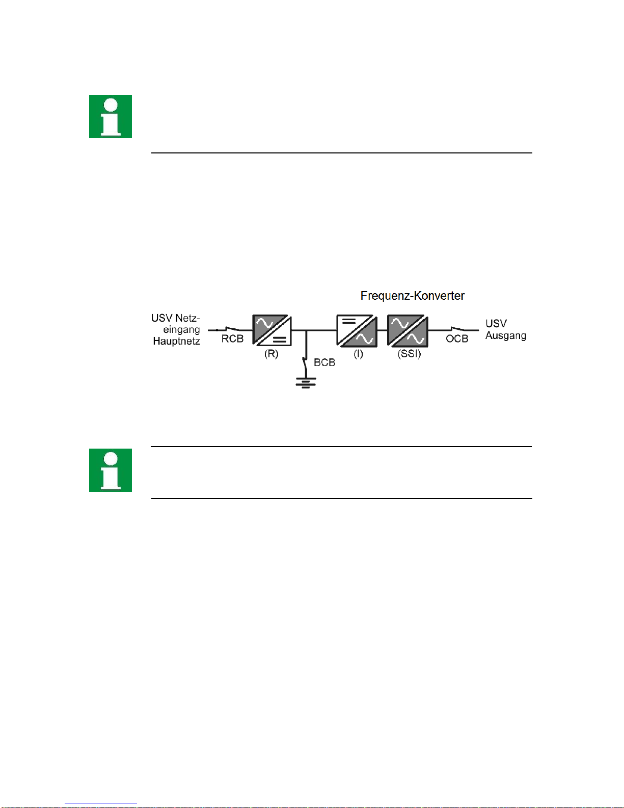
UPS: MKD 700 – 3000 VA RT (XL) UPS Device Description
The operating mode (ECO-MODE) is not recommended for sensitive loads as
many malfunctions such as, e.g. transients, penetrates the by-pass and could
affect the loads. The same applies as long as the UPS is not fed over the public
network but rather by a generator.
Converter mode (CVF MODE)
In addition to the customary operating modes, the UPS can also be switched to
the converter mode. In this, the UPS performance is functionally equivalent to
the standard operating mode but the UPS output is not mapped to the power
input. Rather, the INVERTER (converting) works according to fixed output
values, regardless of the network size is on the input. In this way, a load that
was not initially fit for the available power supply can be supported and operated
here.
Fig. 3-6 Operating mode: CVF MODE
In the event the converter mode is used, there should not be any by-pass
connection to the output because the adjusted output parameters here would be
lost in the event of a by-pass switch.
UPS: MKD 700 – 3000 VA RT (XL) UPS Device Description
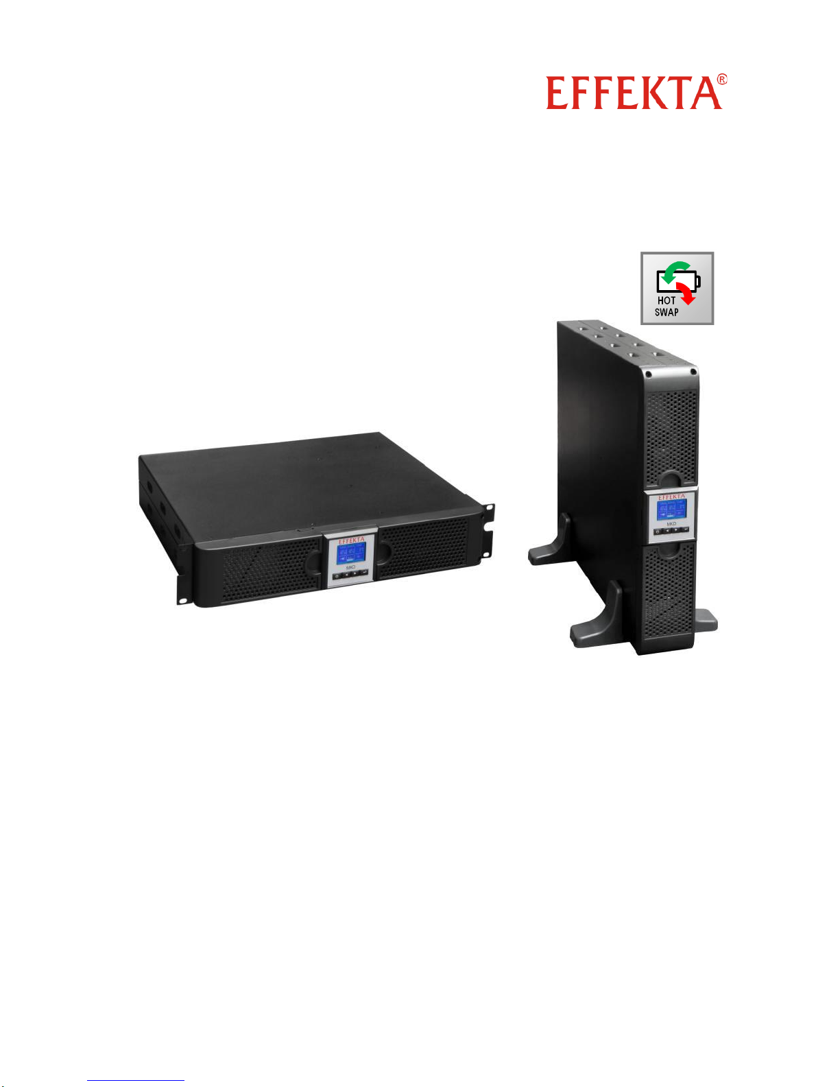
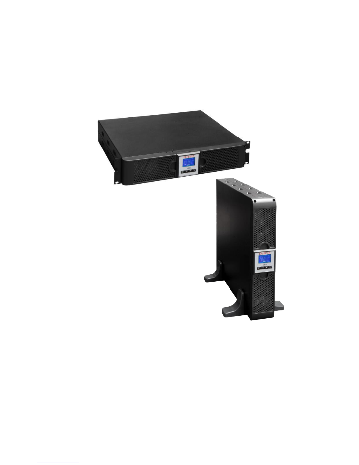
3.2 The device series, format and housing sizes
The MKD 700 – 3000 VA series is manufactured in various performance
versions and with an XL variant for each version. All versions are housed in a
combined housing format (RACK / TOWER). A housing size (2 HE) employs the
corresponding power values.
Fig. 3-7 Die MKD RT series can be used as a conventional RACK mounting
unit (top) or as a TOWER standing unit (bottom).
All devices can fundamentally be operated with an external battery bank
whereby the entire capacity through the addition comes from the internal and
external battery banks. However, connecting an external battery bank to a
standard device is not recommended due to the low charging current.
Therefore, the XL versions of the devices have been specially equipped with a
more efficient charging unit to also charge external battery banks (high capacity)
within a reasonable charging period and, consequently, achieve an acceptable
duration for continuity of service.
UPS: MKD 700 – 3000 VA RT (XL) UPS Device Description
3.3 The device components and connection areas
The MKD series is based on 19” rack housing. All device components for
operation are arranged on the front of the device and those for the connection
are on the back of the device. The only exception to this is the external battery
bank connection which is found under the respective front panel on both of the
devices (UPS and battery bank). Additionally, some differences exist in the
respective XL variants in comparison to the standard versions. This concerns
varying assemblies and functionalities. For this, see the following figures and
descriptions:
Fig. 3-8 Perspective view of the MKD 700 - 3000 VA series (Standard and XL
Version).
Fig. 3-9 View of the back side of the MKD 700 - 2000 VA (Standard) and 700 1500 VA (XL version).

UPS: MKD 700 – 3000 VA RT (XL) UPS Device Description
Fig. 3-10 View of the back side of the MKD 2000 VA (XL-Variant).
Fig. 3-11 View of the back side of the MKD 3000 VA (Standard Version).
Fig. 3-12 View of the back side of the MKD 3000 VA (XL version).

UPS: MKD 700 – 3000 VA RT (XL) UPS Device Description
Front side:
(A) Front panel of the UPS;
(C) RACK mounting bracket /
(B) Control panel for the UPS;
Base for the TOWER version;
Back side:
(1) Slot for expansion module;
(6) RS232 port;
(2) axial fan units (FAN);
(7) Earth connections;
(3) EPO connection and contact input;
(8) UPS outputs (cold devices);
(4) Contact output connection;
(9) UPS inputs (cold devices or
(5) USB port;
Festanschluss);
All operation and display components for the device are reduced to the control
panel (PANEL) which can be obtained on the front of the device. The control
panel (A) makes a clear display of all status data or device information and the
operation of the UPS (system) possible.
In addition to the information displayed, several operation, warning and alarm
messages and key activation are acoustically supported by the built-in signal
generator (BUZZER). Please see 8 Me actions for the coding of the acoustic
messages.
Some heat loss naturally can arise during the operation of the UPS which must
be convectively lead away. There are ventilation ducts available for this which
enable a sufficient airflow in the longitudinal direction of the device. The
integrated fans (2) assist the circulation when necessary.
The ports and interfaces for the device are marked accordingly and described
further under 5 Installation and connection of the UPS.
In the standard version, the system has a by-pass switch for maintenance work
(MAINTENANCE). Generally, we, however, recommend external manual bypass for use. This BY-PASS switch is independent from the UPS variant and,
when switched on, builds a bridge between the mains power supply and the
loads. At the same time, the UPS is disconnected from both the input and output
sides and thereby disconnected from the installation. Maintenance work can
now be performed without difficulty. For this, see also chapter 15.3 External
by-pass.
UPS: MKD 700 – 3000 VA RT (XL) UPS Device Description
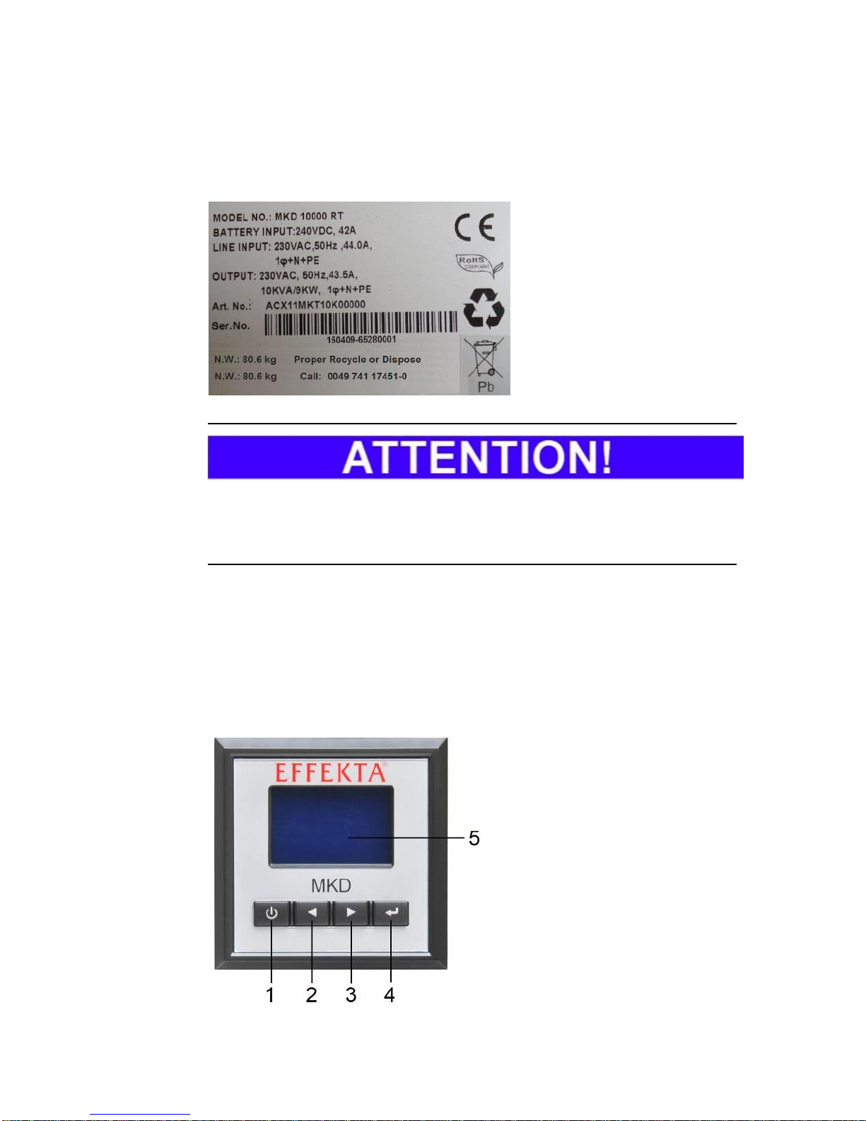
3.3.1 Device label
The following information can be found on the label for the UPS:
the model name;
the data for connection
values;
the article number;
CE label;
serial number (Barcode) for
the device;
weight information.
As a basic principle, compare the label on the device and the present operating
manual for conformity with the device. As a result, this invariably prevents the
improper use of the operation manual and the UPS.
3.3.2 UPS control panel
All important data can be represented, retrieved or set on the control panel of
the UPS. This primarily includes operation parameters, status data or error
codes. The LC display serves as an adequate visual display. The navigation
and input is performed on the keypad below the display. A complete array of all
status messages about all UPS operation modes is summarized under 8 Me.
(1) ON/OFF button (ON/OFF);
(2) Navigation button
“up/back” (UP/BACK);
(3) Navigation button
“down/next” (DOWN/NEXT);
(4) Confirm / select button
(ENTER)
(5) Device display (LCD), with
back lighting
 Loading...