


Uninterruptible Power Supply
MCISeries 700, 1000, 2000, 3000 VA (including the XL variants)
Online Double Converter, TOWER Format
Operating Manual V 2.1
Article Number: ACX11CIS70000000
ACX11CIS1K000000
ACX11CIS2K000000
ACX11CIS3K000000
ACX11CIS70000SXL
ACX11CIS1K000SXL
ACX11CIS2K000SXL
ACX11CIS3K000SXL
Translation of the original Operating Manual

MCI 700, 1000, 2000, 3000 VA (XL) |
Legal notice |
|
|
Legal notice
by EFFEKTA Regeltechnik GmbH
This documentation is solely intended for the operator and his staff. The content of this documentation (texts, figures, drawings, graphics, plans, etc.) may not be copied or distributed in part or in full without our consent in writing, nor can it be used without authorization for competitive purposes or given or made accessible to third parties.
The publication and copyright of this documentation are retained by:
EFFEKTA Regeltechnik GmbH
Rheinwaldstraße 34
D – 78628 Rottweil, Germany
Phone: |
+ 49 (0) 741 17451 |
- 0 |
Fax: |
+ 49 (0) 741 17451 |
- 22 |
E-mail: |
ups@effekta.com |
|
Web: |
www.effekta.com |
|
Operating Manual: |
V 2.1 |
Language: |
English |
Release date: |
01/2018 |
We reserve the right to make changes to the design and the system that will improve the system, the production process or the product.
MCI series |
2 |
|
|

MCI 700, 1000, 2000, 3000 VA (XL) |
Table of contents |
|
Table of contents |
|
|
1. |
Introduction ............................................................................................................. |
5 |
1.1 |
Preface...................................................................................................................... |
5 |
1.2 |
Validity....................................................................................................................... |
6 |
1.3 |
Storage...................................................................................................................... |
6 |
1.4 |
Abbreviations, Terms and Symbols............................................................................ |
6 |
1.5 |
Information Obligation................................................................................................ |
9 |
1.6 |
Warranty Conditions ................................................................................................ |
10 |
1.7 |
Limitation of Liability ................................................................................................ |
11 |
2. |
Safety Instructions ................................................................................................ |
12 |
2.1 |
Introduction.............................................................................................................. |
12 |
2.2 |
Proper Use .............................................................................................................. |
12 |
2.3 |
Avoiding Personal Injuries / Property Damage ......................................................... |
13 |
2.4 |
Protecting the environment ...................................................................................... |
13 |
2.5 |
Transport and Storage............................................................................................. |
13 |
2.6 |
Positioning............................................................................................................... |
14 |
2.7 |
Connection .............................................................................................................. |
14 |
2.8 |
Operation................................................................................................................. |
15 |
2.9 |
Working with Accumulators...................................................................................... |
15 |
2.10 |
Maintenance, Service and Malfunctions................................................................... |
16 |
3. |
UPS Device Description ....................................................................................... |
18 |
3.1 |
Topology and Operating Modes............................................................................... |
18 |
3.2 |
The Device Series, Format and Casing Dimensions ................................................ |
21 |
3.3 |
The USP and its Components in Detail ................................................................... |
22 |
4. |
Storage and Unpacking......................................................................................... |
29 |
4.1 |
Storage of the USP.................................................................................................. |
29 |
4.2 |
Moving the USP to the Installation Site .................................................................... |
29 |
4.3 |
Unpacking and Positioning of the USP .................................................................... |
30 |
5. |
Installation and Connection of the USP ............................................................... |
31 |
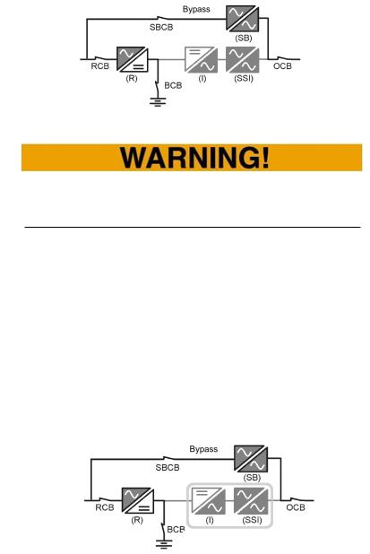
5.1 |
External BYPASS .................................................................................................... |
32 |
5.2 |
Preparing Linkups.................................................................................................... |
33 |
5.3 |
Connection of the USP ........................................................................................... |
34 |
6. |
Operation ............................................................................................................... |
39 |
6.1 |
Operation and Operating Behavior of the UPS Equipment....................................... |
39 |
6.2 |
UPS Settings ........................................................................................................... |
45 |
7. |
Commissioning of the UPS................................................................................... |
48 |
MCI series |
3 |
|

MCI 700, 1000, 2000, 3000 VA (XL) |
Table of contents |
|
8. |
Signals, Error Codes and Troubleshooting Measures |
........................................ 49 |
9. |
Troubleshooting .................................................................................................... |
52 |
10. |
Service-Hotline....................................................................................................... |
52 |
11. |
Software ................................................................................................................. |
53 |
12. |
Maintenance and Service ...................................................................................... |
54 |
12.1 |
Measuring Back-up Time (Autonomy Period)........................................................... |
54 |
12.2 |
Replacing Components / Accumulators ................................................................... |
55 |
12.3 |
Maintenance and Service Contracts ........................................................................ |
56 |
12.4 |
Service Log.............................................................................................................. |
57 |
13. |
Technical Data ....................................................................................................... |
58 |
13.1 |
Typical Autonomy Periods ....................................................................................... |
59 |
14. |
Scope of Delivery / Accessories ........................................................................... |
60 |
15. |
Optional Accessories ............................................................................................ |
61 |
15.1 |
External Accumulator Bank and Connection Cable .................................................. |
61 |
15.2 |
External BYPASS .................................................................................................... |
61 |
15.3 |
Communikation Adapter SNMP ............................................................................... |
62 |
15.4 |
Communikation Adapter, Relay Card (AS400) ......................................................... |
63 |
16. |
Wearing Parts List ................................................................................................. |
64 |
17. |
Conformity Declarations ....................................................................................... |
64 |
MCI series |
4 |
|
|
MCI 700, 1000, 2000, 3000 VA (XL) |
Introduction |
|
|
1.Introduction
1.1Preface
Dear Operator,
This manual is required for the operation of the uninterruptible power supply described herein.
It should give you support for working responsibly and provide basic information about the uninterruptible power supply, namely on how it operates, its application and in addition, what you should do in the event of malfunctioning. Furthermore, this operating manual contains instructions for the transport and storage as well as the handling and installation of the uninterruptible power supply.
The planning guidelines in this operating manual only relate to special requirements and characteristics of the uninterruptible power supply. All national and local provisions and regulations for electrical installations have to be adhered to in the installation process. The same applies to the operation of the device.
The content of this manual may change due to technological progress. We have done our best to present the content correctly and clearly. If, however, we have made errors, we would be grateful if you would let us know.
We do not assume any liability for errors in this operating manual or any consequences resulting thereof.
The uninterruptible power supply is intended to protect sensitive electronic systems and equipment from interferences that could occur due to bad electric quality or grid failures.
Please read this operating manual carefully and take note particularly of the safety instructions!
If you have questions about the device, the technical supervisor in your company or our employees will gladly assist you.
Your
EFFEKTA Regeltechnik GmbH
MCI series |
5 |
|
|

MCI 700, 1000, 2000, 3000 VA (XL) |
Introduction |
|
|
1.2Validity
The descriptions in this operating manual relate solely to the uninterruptible power supply (UPS) defined in the technical data as a whole or as it refers to modules, components and individual parts that were developed and built by EFFEKTA Regeltechnik GmbH ( Chapter13. Technical Data).
Read this documentation carefully and familiarize yourself with the product before you start operating it.
1.3Storage
The operating manual for the device must be stored in the vicinity of the equipment at all times so it is immediately available if need be.
Pass this manual on to any subsequent users of the product.
1.4Abbreviations, Terms and Symbols
In this manual, the abbreviation UPS stands for: uninterruptible power supply.
Typically, accumulators are used as energy storage of the UPS-equipment. Colloquially these are referred to as batteries or rechargeable batteries. Consequently, accumulator bank is the term used for the aggregation of several accumulators into a group, which form the energy storage.
Danger, Warning, and Attention references are explicitly marked by the respective symbols (pictograms) and must be adhered to without fail. See the following list and explanations:
Danger / Warning Levels / Notes:
Text that is marked with DANGER! provides a warning about dangers. If accident prevention measures are not taken, these dangers result in serious (irreversible) injuries or even death!
MCI series |
6 |
|
|

MCI 700, 1000, 2000, 3000 VA (XL) |
Introduction |
||
|
|
|
|
|
|
|
|
Text that is marked with WARNING! provides a warning about hazards. If accident prevention measures are not taken, these dangers may result in serious (irreversible) injuries or even death!
Text that is marked with CAUTION! provides a warning about hazards. If accident prevention measures are not taken, these dangerous situations can lead to slight or medium reversible injuries.
Text that is marked with NOTICE! contains very important instructions for situations that, if accident prevention measures are not taken, may result in damage to the product and / or its functions or an object in its vicinity.
This symbol indicates text that contains instructions / comments or tips.
Warning about danger spots:
General warning about danger spots!
MCI series |
7 |
|
|

MCI 700, 1000, 2000, 3000 VA (XL) |
Introduction |
|
|
Specific warning:
Warning about dangerous electrical voltage!
Warning about proper handling of accumulators!
Instruction symbols:
Take note of the provided documentation(s) and/or instructions!
Disconnect prior to additional work!
Environment protection symbols:
Identifies instructions for recycling.
Identifies components that are subject to the Electronic Scrap Regulation.
Identifies components or parts that must be disposed of. Do not discard these with household waste.
MCI series |
8 |
|
|
MCI 700, 1000, 2000, 3000 VA (XL) |
Introduction |
|
|
Text symbols:
●This dot marks descriptions of activities that you should carry out.
Requirement that must be fulfilled, for example:The DC circuit breaker is in "OFF" position.
–This dash marks specification lists.
This arrow marks a cross reference.
If a cross reference to another chapter is necessary in the text, this is shortened for clarity.
Example: OM, 2 Safety Instructions This means: See Operating Manual,
Chapter 2 Safety Instructions.
If the cross reference refers to a page, figure or position number, this information is added at the end of the cross reference.
Example: |
Fig. 4-4, Pos. 1 |
This means: |
see position number 1 in |
|
figure 4 in chapter 4 of this Operating Manual. |
(3)Numbers in brackets refer to the positions in the figures.
**Annotations within the text are marked with ** and explained accordingly.
1.5Information Obligation
This operating manual must be read and understood by all persons and qualified personnel working with this device (this equipment).
This applies in particular to maintenance, operating and cleaning personnel including persons responsible for transportation and/or disposal.
EFFEKTA Regeltechnik GmbH is not liable for damage incurred or caused by staff who have not been trained or who have been insufficiently trained!
MCI series |
9 |
|
|
MCI 700, 1000, 2000, 3000 VA (XL) |
Introduction |
|
|
1.6Warranty Conditions
The receipt of delivery is considered as the record for the initial purchase and should be kept in a safe place. It will be necessary for making any warranty claims. If the product is passed on to another user, that user has the right to make warranty claims for the remainder of the warranty period. The purchase receipt as well as this declaration should also be given to the new owner if the device is passed on.
We warrant that this device, upon delivery, is in a functional state and technically conforms to the descriptions in the appended documentation.
The warranty period for UPS-devices corresponds to the minimum periods stipulated by law.
However, the warranty does not apply to the following cases:
–if the defect is caused by: freight damage, accident, natural catastrophes, misuse, vandalism;
–in case of improper use, defective maintenance or incorrect repair by third parties;
–in the event of changes, unauthorized intervention, incorrect operation, false installation or other modifications not approved by us;
–in case of improper use such as connection of the device to unsuitable energy sources or unsuitable loads, or in general use in an unsuitable environment, etc.;
–in the event of failure to follow instructions in the provided documentation;
–for any defects caused by a lack of due care, e.g. splash water, etc.;
–in the event that the product is incompatible due to possible technical innovations or regulations that occur after the purchase;
–in case of malfunctions or damage caused by the connection to incompatible devices or accessories;
–in the event of developments that are related to the normal aging process of the product (wear parts), Example: shortened battery life at elevated ambient temperature (above 25°C).
–in the event of defects that were caused by external fixtures, e.g. power strips, etc.;
–in the event of failure to provide due maintenance and care for the product;
The warranty period for replaced and/or repaired parts as part of this warranty expires together with the original warranty for the product.
MCI series |
10 |
|
|
MCI 700, 1000, 2000, 3000 VA (XL) |
Introduction |
|
|
Devices that are supplied without accessories are equally replaced without accessories. The return of the device is only accepted if this is done in the original packaging.
Incurred transport costs are generally not included in the warranty.
Repair and exchange of the device will in general be at your cost.
We are not liable for any damage or consequential damage, whether they were incurred directly, unintentionally or due to negligence.
EFFEKTA Regeltechnik GmbH does not provide either explicit or implicit warranties with regard to this device's quality, performance, salability or suitability for a certain purpose. In some countries, the exclusion of implicit warranties is not permitted by law. In this case, the validity of all explicit and implicit warranties is limited to the warranty period. With the expiration of these periods, all warranties lose their validity. In some countries, a limitation of the validity period of implicit warranties is not permitted by law so that the aforementioned limitation does not take effect.
1.7Limitation of Liability
Claims to damage compensation are excluded unless they involve intent or gross negligence by EFFEKTA Regeltechnik GmbH or its employees. This does not affect liability according to the Product Liability Act. Under no circumstances are we liable for:
–claims that third parties make against you due to losses or damage;
–loss or damage of your records or data or the costs of recovering this data;
–economic subsequent damage (including lost profits or savings) or concomitant damage, including in the event that we were informed of the possibility of such damage;
Under no circumstances is EFFEKTA Regeltechnik GmbH responsible for any accidental, indirect, specific, subsequent or other damage of any kind (including, without any limitation, damage related to a loss of profits, interruption of business, loss of business information, or any other losses) that result from use of the device or are connected with the device whether they are based on the contract, damage compensation, negligence, strict liability or other claims, even if EFFEKTA Regeltechnik GmbH was informed about the possibility of such damage in advance. This exemption also includes any liability that can result from the claims of third parties against the initial purchaser.
In some countries, the exemption or the limitation of concomitant or subsequent damage is not permitted by law so that the aforementioned declaration does not enter into force.
MCI series |
11 |
|
|

MCI 700, 1000, 2000, 3000 VA (XL) |
Safety Instructions |
|
|
2.Safety Instructions
2.1Introduction
The UPS is a device that has been produced according to the rules and regulations of technology for an uninterruptible power supply.
The device is safe when used properly and under consideration of the safety requirements and
instructions provided in this operating manual.
2.2Proper Use
The UPS and its related components may only be used for purposes in accordance with its design – to supply electric appliances from a primary source and to provide a short-term supply for the appliances from a secondary source, which does not exceed the nominal power in total. Any other use beyond that is considered improper and can result in personal injury, damage to property or to the device!
The device is not designed for use in
–explosive;
–dusty or humid;
–radioactive or;
–biologically or chemically contaminated atmospheres!
For information of the respective IP protection class of the device please contact our service centers.
In addition, the device class with regard to “electromagnetic compatibility”
(EMC) has to be taken into consideration. There is no radio interference to be expected with devices of Class C1. However, devices classified as Class C2 can cause radio interference in the home/residential areas. In this case, the operating party may be requested to take appropriate remedial measures! Therefore, please take note of the information regarding the device category in the specifications listed (13 Technical Data).
MCI series |
12 |
|
|

MCI 700, 1000, 2000, 3000 VA (XL) |
Safety Instructions |
|
|
2.3Avoiding Personal Injury / Property Damage
–Please read this operating manual carefully to familiarize yourself with the device and its functionality. Do not, under any circumstances, ignore the safety instructions.
–In particular, take note of the information regarding the installation and commissioning of the device.
–Only operate the product only in an appropriate and proper way and always within the specified performance parameters. (13 Technical Data).
–Only perform maintenance and service work that is described in the documentation. Follow the instructions steps as specified. Only use original replacement parts from EFFEKTA Regeltechnik GmbH
2.4Protecting the Environment
Send the product back to EFFEKTA Regeltechnik GmbH after the end of its service life. We will ensure environmentally responsible disposal.
2.5Transport and Storage
The UPS may only be transported to the intended location in the original packaging. The same applies to moves or returns.
The packaging has a very good protective function with regard to the device. By inversion of this argument, all devices that were damaged in the course of transportation must be inspected by EFFEKTA Regeltechnik GmbH prior to their commissioning. The same applies in general for any damage to the device.
If the period of storage exceeds 4 months, the accumulator bank of the UPS equipment must urgently be charged; see also 4.1 Storage of the UPS.
Due to the possibility of existing energy storage (accumulators) within a UPS, devices must in general be inspected by EFFEKTA Regeltechnik GmbH or a qualified service center after transportation damages. Every transportation damage carries the high risk that the energy storage units and/or their electrical connections have been affected. As a result, short circuits and/or the leaking of electrolytes cannot be ruled out. For this reason, the isolation of the unit is necessary, until an inspection has been performed.
In addition, the device may not be transported or stored upside-down.
MCI series |
13 |
|
|

MCI 700, 1000, 2000, 3000 VA (XL) |
Safety Instructions |
|
|
2.6Positioning
Only operate the UPS in well ventilated rooms, within the specified ambient temperature range (according to 13 Technical Data).
The UPS may not be placed in the vicinity of heat sources.
Always take the operating position into account when positioning the device.
Maintain the minimum distance to adjacent equipment and walls required for ventilation purposes (see 13 Technical Data and 5 UPS Installation and Connection). Ensure that the necessary air circulation is provided.
Never place or operate the device in a moist environment. Liquids must generally kept away from the device.
Due to major temperature differences, condensation or dew effects may occur after the positioning of the UPS. Therefore, an acclimatization period of at least 2 hours is to be observed, before you take additional steps. Make sure that the temperature adjustment has been completed and that any surfaces with condensation inside and outside the device have completely dried.
Never operate the UPS in an combustible and/or unventilated environment.
2.7Connection
Always use the connection terminals provided for this purpose for the connection of the UPS.
To avoid electrical hazards, the connection of the unit may only be made under de-energized conditions.
The PE (protective earth conductor) must be connected without fail. The device and the connected loads may not, under any circumstances, be used without the PE!
The UPS output is supplied with power even in the event of a power outage; according to the provisions included in EN62040-1, the lines and power outlets supplied by the UPS must be clearly marked!
In addition, the following aspects must always be complied with when connecting the UPS:
MCI series |
14 |
|
|

MCI 700, 1000, 2000, 3000 VA (XL) |
Safety Instructions |
|
|
–Install all connections appropriately and keep the cable length as short as possible;
–Only use suitable power cables for the connection of the UPS with the electricity grid and ensure the required current carrying capacity;
–Only use suitable power cables for the connection of the loads with the UPS and ensure the required current carrying capacity;
–The safeguarding of any appliance must always be immediately in front of an appliance and may never be done centrally in front of the UPS;
–Never operate any household devices or tools like e. g. fan heaters, vacuum cleaners, electric drills, hair dryers, toasters, etc. via the UPS.
–Do not connect any appliance to the UPS that could overload the device;
–Only use appropriate suitable tools for the installation;
2.8Operation
Access to the unit as well as its operation is reserved to qualified personnel only.
Attention must always be paid to the fact that the UPS includes an energy storage or is connected to an external energy storage unit. This means that the outlet of the UPS can be current-carrying even when the UPS is already disconnected from the mains power supply.
Consequently, the UPS output is only guaranteed to be de-energized, when the device is completely shut down and disconnected from the mains power supply
2.9Working with Accumulators
When handling accumulators there is always a risk of electric shocks, burns and/or chemical burns.
Therefore, unauthorized persons should never have access to the accumulators.
MCI series |
15 |
|
|

MCI 700, 1000, 2000, 3000 VA (XL) |
Safety Instructions |
||
|
|
|
|
|
|
|
|
Accumulators and their circuit points can cause electric shocks.
In the event of a short-circuit of the accumulators, touching the current-carrying parts can result in severe burns.
Do not place accumulators in the vicinity of heat sources and do not bring them in contact with open fire. Explosion hazard!
Furthermore, never open or destroy accumulators. The released electrolyte presents a great danger to health and the environment. It could result in chemical burns to skin and eyes, and electrolyte is very toxic.
Defective accumulators have to be disposed of in an environmentally compatible manner!
Never dispose of accumulators with regular household waste!
Local disposal regulations must be observed!
2.10Maintenance, Service and Malfunctions
Attention – Danger of electric shocks.
Even after switching off the supply with the power button or after disconnecting the accumulator feed respectively, parts of the UPS can still carry high voltages.
MCI series |
16 |
|
|

MCI 700, 1000, 2000, 3000 VA (XL) |
Safety Instructions |
||
|
|
|
|
|
|
|
|
The following aspects have to be considered, when carrying out work on the UPS or the accumulators:
–Before you begin any work on the UPS, it must be switched of and disconnected from the power grid and from all the appliances.
–Remove wrist watches, jewelry and other metallic objects;
–Use only isolated tools;
–Work on live equipment may only be carried out by specially trained qualified personnel. They must always wear the appropriate personal protective equipment (PPE);
–As a rule, the UPS may not be disassembled.
–Only trained electricians with sufficient knowledge of the required safety regulations may perform work on accumulators or supervise such work tasks;
–Unauthorized persons should not have access to the UPS and the accumulators;
MCI series |
17 |
|
|

MCI 700, 1000, 2000, 3000 VA (XL) |
Device Description |
|
|
3.UPS Device Description
This UPS-unit is an ONLINE-UPS according to the double conversion principle. The UPS receives the classification "Class 1 (VFI-SS-111) due to the excellent operating performance pursuant to EN62040-4. Consequently, any appliances connected via the unit can be ideally supplied, regardless of the performance of the primary energy source (mains power supply).
Malfunctioning like: mains failure, low voltage on the mains power supply, grid overvoltage, short-term grid alterations (transients), gradual supply voltage deviations, frequency changes, etc. are not transmitted to the connected loads under normal and autonomous operation.
The UPS is designed to provide a consistent power supply to sensitive devices and equipment like, e.g.: computers, servers, emergency systems, electronic cash registers, operations-critical instruments, telecommunication facilities, process control, monitoring and control systems, etc.
The MCI-Series includes an internal accumulator bank as secondary energy source. A possible extension of autonomy periods is possibly through the adaption of an external accumulator bank or the extension of its capacity. If very high autonomy periods (capacities) are required, the XL models must be used, as these models provide a significantly higher charging rate.
3.1Topology and operating modes
The following diagram (Fig. 3-1), a block diagram of the UPS-unit, clearly shows the double conversion principle. The mains power supply is converted into the DC-intermediate circuit, which charges the energy storage (accumulator). Through an additional conversion (INVERTER) the connected loads on the UPS output are supplied without malfunction or interruption.
UPS mains |
|
|
|
UPS |
|
power supply |
|
|
|
output |
|
input |
|
|
|
|
|
|
|
|
|
|
|
Fig. 3-1 Topology, functional groups of the UPS-equipment.
As can clearly be seen, no power failures or disruptions of and within the mains power supply reach the UPS output and thus the loads. In addition, all operating modes of the UPS-system can be derived and described from the above block diagram:
MCI series |
18 |
|
|

MCI 700, 1000, 2000, 3000 VA (XL) |
Device Description |
|
|
Normal operating mode (INVERTER-MODE)
The normal operating mode is characterized here by the typical double conversion. The mains power supply is converted into the DC intermediate circuit, which in turn feeds the UPS output via the inverter (DC/AC converter). In this mode, the BYPASS is inactive.
UPS mains |
|
|
|
||
power supply |
|
UPS |
input |
|
|
|
output |
|
|
|
|
|
|
|
|
|
|
Fig. 3-2 Operating mode: Normal operation.
Back-up or autonomous mode (BATTERY-MODE)
In the event of a temporary mains failure, the inverter feeds directly from the accumulator bank and supplies the UPS-output without interruption this way. The autonomous mode is limited by the capacity of the accumulator bank and its charging condition.
UPS mains
power supply
input UPS output
Fig. 3-3 Operating mode: Autonomous operation.
Static by-pass mode (FAULT MODE)
Usually due to a device error (fault mode) inside the inverter, the UPS automatically and without interruption switches the UPS output to static BYPASS mode. This ensures that the power supply to the loads is maintained. from the mains power supply, however, without the support function of the UPS. Once the malfunction is cleared, the equipment returns to normal operating mode. Malfunction can also be cause by the connected appliances, e.g. when the UPS is overloaded.
MCI series |
19 |
|
|
MCI 700, 1000, 2000, 3000 VA (XL) |
Device Description |
|
|
UPS mains |
UPS |
|
power supply |
||
output |
||
input |
||
|
Fig. 3-4 Operating mode: Static BYPASS.
Do not leave the UPS in static by-pass mode or fault mode for any extended period of time. Even though the appliances continue to be supplied, no backup support function is provided by the UPS.
The static BYPASS mode can also be set manually on purpose, e.g. for inspection purposes.
The energy saving mode (ECO MODE)
One special feature of the MCI series is its "energy saving mode", called ECOMODE. For this, the UPS device is intentionally operated in static BYPASS mode. In this mode, the inverter remains inactive but ready for operation, and as a result, the system consumes significantly less power (LINE-INTERACTIVE). Only in the event of a mains failure / mains malfunction or disruption the UPS automatically switches into autonomous mode. However, the application of the ECO-MODE recommended, if the loads are “robust” devices that are able to tolerate the minor switching and grid fluctuations during BYPASS mode.
UPS mains |
|
power supply |
UPS |
input |
output |
Inverter on standby!
Fig. 3-5 Operating mode: ECO-MODE (static BYPASS).
MCI series |
20 |
|
|
MCI 700, 1000, 2000, 3000 VA (XL) |
Device Description |
|
|
This operating mode (ECO-MODE) is not recommended for sensitive loads, as certain disturbances like, for example, transients can penetrate the by-pass and can affect the loads. The same is true, if the UPS is not supplied from the public power grid, but alternatively from a generator.
Converter Mode (CVF MODE)
In addition to the standard operating modes, the UPS can also be switched into a converter mode. In this mode, the UPS operates functionally equivalent to its normal operating mode, however, the UPS output is not mapped to the mains input, rather, the INVERTER operates (convertingly) according to defined output parameters, irrespective of the power units at the input. This means, an appliance can be supported and operated that would in fact not be compatible with the available grid.
3.2The device series, format and casing dimensions
The MCI series is produced in several performance variations including an XL model for each variant. See the following table:
|
Description |
|
Capacity |
|
Article number: |
|
Casing: |
|
Note: |
|
|
[VA] |
|
|
|
||||
|
|
|
|
|
|
|
|
|
|
|
|
|
|
|
|
|
|
|
|
MCI-700 |
700 |
|
ACX11CIS70000000 |
|
M |
|
standard |
||
|
|
|
|
|
|
|
|
||
MCI-1000 |
1000 |
|
ACX11CIS1K000000 |
|
M |
|
standard |
||
|
|
|
|
|
|
|
|
||
MCI-2000 |
2000 |
|
ACX11CIS1K000000 |
|
L |
|
standard |
||
|
|
|
|
|
|
|
|
||
MCI-3000 |
3000 |
|
ACX11CIS1K000000 |
|
L |
|
standard |
||
|
|
|
|
|
|
|
|
|
|
MCI-700 XL |
700 |
|
ACX11CIS70000SXL |
|
M |
|
high charging ca- |
||
|
|
|
pacity |
||||||
|
|
|
|
|
|
|
|
|
|
MCI-1000 XL |
1000 |
|
ACX11CIS1K000SXL |
|
M |
|
high charging ca- |
||
|
|
|
pacity |
||||||
|
|
|
|
|
|
|
|
|
|
MCI-2000 XL |
2000 |
|
ACX11CIS1K000SXL |
|
L |
|
high charging ca- |
||
|
|
|
pacity |
||||||
|
|
|
|
|
|
|
|
|
|
MCI-3000 XL |
3000 |
|
ACX11CIS1K000SXL |
|
L |
|
high charging ca- |
||
|
|
|
pacity |
||||||
|
|
|
|
|
|
|
|
|
|
All variants are housed in the standard free-standing case (TOWER). Correlating to the power output values, two casing sizes are being used (M and L).
All models can in general be operated with an external accumulator bank, whereby the total capacity equals the sum of the capacity of the internal and the external accumulator bank. The accumulator banks too are housed in casings of the same dimensions (M and L), depending on the UPS model.
Models of the XL variation are equipped with more powerful charging units, to load external accumulator banks with high capacities within the regular charging time, and as a result to reduce recovery times.
MCI series |
21 |
|
|
 Loading...