

Photovoltaic Solar Inverter Series ES
ES2200 / ES3300 / ES4200 / ES5000
Operating Manual V. 3.2
Article number: SLWRABSI2K0Wx000
SLWRABSI3K0Wx000
SLWRABSI4K0Wx000
SLWRABSI5K0Wx000
Translation of the original Operating Manual
Photovoltaic Solar Inverter Series ES
Legal notice
ES series
2
Legal notice
by EFFEKTA Regeltechnik GmbH
EFFEKTA Regeltechnik GmbH, 78628 Rottweil, retains the copyright to this
documentation.
This documentation is solely intended for the operator and his staff. The
content of this documentation (texts, figures, drawings, graphics, plans, etc.)
may not be copied or distributed in part or in full without our consent in writing,
nor can it be used without authorisation for competitive purposes or given or
made accessible to third parties.
EFFEKTA Regeltechnik GmbH
Rheinwaldstraße 34
D – 78628 Rottweil
Phone: + 49 (0) 74 1 / /1 74 51 - 0
Fax: + 49 (0) 74 1 / /1 74 51 - 22
E-mail: ups@effekta.com
Internet: www.effekta.com
Manual: Operating manual
Language: English
Release date: 03/2011
We reserve the right to make changes to the design and the system that
will improve the system, the production process or the product.

Photovoltaic Solar Inverter Series ES
Contents
ES series
3
Contents
1. Introduction ............................................................................................................. 5
1.1 Foreword ................................................................................................................... 5
1.2 Validity ...................................................................................................................... 6
1.3 Storage ..................................................................................................................... 6
1.4 Symbols in this Manual .............................................................................................. 6
1.5 Information Obligation ..............................................................................................10
1.6 Warranty Conditions .................................................................................................10
1.7 Transport and Storage ..............................................................................................12
1.8 Positioning................................................................................................................13
2. Safety Instructions .................................................................................................14
2.1 Introduction ..............................................................................................................14
2.2 Proper Use ...............................................................................................................14
2.3 Avoiding Personal Injury / Property Damage ............................................................15
2.4 Protecting the environment .......................................................................................15
2.5 Connection ...............................................................................................................16
2.6 Advice about specific dangers ..................................................................................17
2.7 Operation .................................................................................................................18
2.8 Working with PV modules .........................................................................................18
2.9 Maintenance, Service and Malfunctions ...................................................................19
2.10 Advice about connecting to the mains power ............................................................19
3. Device Description .................................................................................................20
3.1 Dimensions ..............................................................................................................20
3.2 Display and connections ...........................................................................................21
4. Assembly ................................................................................................................23
4.1 Assembly of the wall mounting .................................................................................23
4.2 Ambient conditions for assembly ..............................................................................25
4.3 Assembling photovoltaic solar inverters ....................................................................29
5. Electrical Installation ..............................................................................................31
5.1 Connecting AC power cable ..................................................................................... 32
5.2 Connecting PV module .............................................................................................36
6. Control Panel ..........................................................................................................41

Photovoltaic Solar Inverter Series ES
Contents
ES series
4
7. Commissioning ...................................................................................................... 43
7.1 Starting device for the first time ................................ ................................................ 44
7.2 Country settings, operating mode settings and ID settings ....................................... 45
7.3 Commissioning the photovoltaic solar inverter ......................................................... 47
7.4 Checking measurement readings and numbers ....................................................... 49
7.5 Operating states of the photovoltaic solar inverter .................................................... 52
8. Communication Interfaces .................................................................................... 54
8.1 Standard communication interface ........................................................................... 54
8.2 Solar-LogTM .............................................................................................................. 55
8.3 Optional data cards .................................................................................................. 55
9. Status Diagnosis and Troubleshooting ................................................................ 65
9.1 Error codes and explanations .................................................................................. 65
9.2 Mains error alarm codes and explanations ............................................................... 68
10. Service .................................................................................................................... 70
11. Technical Data ....................................................................................................... 71
11.1 Device specifications ............................................................................................... 71
11.2 ES2200 / ES3300 Block diagram ............................................................................. 74
11.3 ES4200 / ES5000 Block Diagram ............................................................................ 75
11.4 Scope of Delivery / (Optional) Accessories .............................................................. 76
12. Declaration of Conformity ..................................................................................... 80

Photovoltaic Solar Inverter Series ES
Introduction
ES series
5
1. Introduction
1.1 Foreword
Dear Operator,
You are about to operate a photovoltaic solar inverter.
This operating manual should provide you with support for working responsibly
and basic information about the photovoltaic solar inverter, namely how it
operates, its application and what you should do in the event of malfunctioning.
Furthermore, this operating manual contains instructions for the transport and
storage as well as the handling and installation of the photovoltaic solar
inverter.
The plan guidelines in this operating manual only relate to special requirements
for the photovoltaic solar inverter. During installation, make sure you follow the
national and local requirements for electrical installations.
The content of this device description may change due to technological
progress. We have tried to present the content correctly and clearly. If,
however, we have made errors, we would be grateful for information about this.
The photovoltaic solar inverter is intended to convert the energy generated
by solar modules into 230 VAC and to feed it into the power grid.
Please read this operating manual carefully and take note particularly of
the safety instructions.
If you have questions about the device, the technical supervisor in your
company or our employees will be glad to help you.
Your
EFFEKTA Regeltechnik GmbH
Photovoltaic Solar Inverter Series ES
Introduction
ES series
6
1.2 Validity
The descriptions in this operating manual relate solely to the
Photovoltaic solar inverter
defined in the technical data as a whole or as it refers to modules, components
and individual parts that were developed and built by EFFEKTA Regeltechnik
GmbH.
11. Technical Data
1.3 Storage
This operating manual for the device must be stored in the vicinity of the device
at all times so it is immediately available if need be.
1.4 Symbols in this Manual
The abbreviation PV in this manual stands for photovoltaic.
Read this documentation carefully and make yourself familiar with the
product before using it.
Store this operating manual in an easily accessible place to refer to it if
necessary.
Please pass this operating manual on to later users of the product.
1.4.1 Danger warning levels
Text that is marked with DANGER! provides a warning about dangers. If
accident prevention measures are not taken, these dangers may result in
serious (irreversible) injuries or even death!
Photovoltaic Solar Inverter Series ES
Introduction
ES series
7
Text that is marked with WARNING! provides a warning about hazards. If
accident prevention measures are not taken, these hazards may result in
serious (irreversible) injuries or even death!
Text that is marked with CAUTION! provides a warning about hazards. If
accident prevention measures are not taken, these dangerous situations
can lead to slight or medium reversible injuries.
Text that is marked with ATTENTION! contains very important
instructions for situations that, if accident prevention measures are not
taken, may result in damage to the product and / or its functions or an
object in its vicinity.
This symbol indicates text that contains important instructions / comments or
tips.
Photovoltaic Solar Inverter Series ES
Introduction
ES series
8
1.4.2 Warning information
1.4.2.1 Warning about danger spots
General warning about danger spots!
1.4.2.2 Specific warning
Warning about dangerous electrical voltage!
1.4.3 Instruction symbols
Take note of the provided documentation and/or instructions!
Disconnect before work!

Photovoltaic Solar Inverter Series ES
Introduction
ES series
9
1.4.4 General symbols
●
This dot marks descriptions of activities that you should carry out.
–
This dash marks specifications.
This arrow marks a cross reference.
If a cross reference to another chapter is necessary in the text, this is
shortened for clarity.
Example: OM, 2 Safety Instructions
This means: See Operating Manual, Chapter 2 Safety
Instructions.
If the cross reference refers to a page, figure or position number, this
information is added at the end of the cross reference.
Example: Fig. 4 - 4, Pos. 1
This means: See position number 1 in figure 4 in Chapter 4
of this manual.
(3)
Numbers in brackets refer to the positions in the figures.
Identifies instructions for recycling.
Identifies components that are subject to the Electronic Scrap Regulation.
Identifies components or parts that must be disposed of. Do not throw these
in the household waste.
Requirement that must be fulfilled:
The DC circuit breaker is on "OFF."

Photovoltaic Solar Inverter Series ES
Introduction
ES series
10
1.5 Information Obligation
This operating manual must be read, understood and all its points must be
taken note of by all persons that are responsible for the
– Operation
– Cleaning and
– Disposal
of the device.
EFFEKTA Regeltechnik GmbH is not liable for damage incurred or caused
by staff who have not been trained or who have been insufficiently
trained!
1.6 Warranty Conditions
The receipt of delivery is considered as the record for the initial purchase and
should be kept in a safe place. It will be necessary for making use of the
warranty. If the product is passed on to another user, he has the right to the
warranty for the remainder of the warranty period. The purchase receipt as well
as this declaration should also be given to the new owner if the device is
passed on.
We guarantee that this device, upon delivery, is in a functional state and
technically conforms to the descriptions in the appended documentation.
The warranty period for special devices corresponds to the minimum periods
stipulated by law.
The warranty ceases to apply in the following cases:
In the event of defects caused by: freight damage, accident, natural
catastrophies, misuse, vandalism, improper use, defective maintenance or
incorrect repair by third parties.
– In the event of changes, unauthorised intervention, incorrect operation,
another device or accessories, false installation or other modifications not
approved by us.
– Improper use such as plugging the device into unsuitable energy sources,
attempts to overload the photovoltaic solar inverter, use in an unsuitable
environment, etc.
– In the event of failure to follow instructions in the provided documentation.

Photovoltaic Solar Inverter Series ES
Introduction
ES series
11
– In the event that the product is incompatible due to possible technical
innovations or regulations that occur after the purchase.
– In the event of incompatibility or malfunctioning that was caused by product
components we did not install.
– In the event of developments that are related to the normal aging process
of the product (wear parts).
– In the event of defects that were caused by external fixtures.
The warranty period for replaced and/or repaired parts as part of this warranty
expires together with the original warranty for the product.
Devices that are supplied without accessories are replaced without
accessories. The return of the device is only accepted if this is done in the
original packaging.
Incurred transport costs are generally not included in the warranty.
You shall bear the cost of repair and exchange, and EFFEKTA Regeltechnik
GmbH is not liable for damage, whether directly, unintentionally, specifically, or
for subsequent damage, even if it was caused by negligence or other errors.
EFFEKTA Regeltechnik GmbH does not provide either explicit or implicit
warranties related to this device and its quality, performance, saleability or
suitability for a certain purpose. In some countries, the exclusion of implicit
warranties is not permitted by law. In this case, the validity of all explicit and
implicit warranties is limited to the warranty period. With the expiration of these
periods, all warranties lose their validity. In some countries, a limitation of the
validity period of implicit warranties is not permitted by law so that the
aforementioned limitation does not take effect.

Photovoltaic Solar Inverter Series ES
Introduction
ES series
12
1.6.1 Limitation of liability
Claims to damage compensation are excluded unless they involve intent or
gross negligence by EFFEKTA Regeltechnik GmbH or its employees. This
does not affect liability according to the Product Liability Act. Under no
circumstances are we liable for:
– Claims that third parties make against you due to losses or damage.
– Loss or damage of your records or data or the costs of recovering this
data.
– Economic subsequent damage (including lost profits or savings) or
concomitant damage, including in the event that we were informed of the
possibility of such damage.
Under no circumstances is EFFEKTA Regeltechnik GmbH responsible for
any accidental, indirect, specific, subsequent or other damage of any kind
(including, without any limitation, damage related to a loss of profits,
interruption of business, loss of business information, or any other losses) that
result from use of the device or are connected with the device whether they are
based on the contract, damage compensation, negligence, strict liability or
other claims, even if EFFEKTA Regeltechnik GmbH was informed about the
possibility of such damage in advance. This exemption also includes any
liability that can result from the claims of third parties against the initial
purchaser.
In some countries, the exemption or the limitation of concomitant or
subsequent damage is not permitted by law so that the aforementioned
declaration does not enter into force.
1.7 Transport and Storage
The photovoltaic solar inverter may only be transported to the intended location
in the original packaging. The same applies to moves or returns.
The packaging plays no role as fall protection, so all fallen devices must be
checked by EFFEKTA Regeltechnik GmbH before commissioning.
Photovoltaic Solar Inverter Series ES
Introduction
ES series
13
1.8 Positioning
Do not install in an area in which combustible vapours result e.g. from
petrol tanks, engine compartments, etc.
The photo voltaic solar inverter is designed for operation in ventilated rooms
with an ambient temperature of 0° to 40°C.
If the photovoltaic solar inverter is exposed to severe and quick temperature
changes, there is danger of condensation. Before you take additional steps, an
acclimatisation period of at least 2 hours is to be observed.
Never place or operate the device in a moist environment. Keep liquids away
from the device.
The photovoltaic solar inverter may not be placed in the vicinity of heat
sources.
It is to be placed in a horizontal position.
Ensure that the external side and the front side of the device are at least 20 cm
from other objects for ventilation in order to prevent trapped air and too much
warming. Make sure that the air openings cannot be covered, e.g. through
sucked-in paper, material, etc.
Photovoltaic Solar Inverter Series ES
Safety Instructions
ES series
14
2. Safety Instructions
2.1 Introduction
The photovoltaic solar inverter is a device that has been produced
according to the rules and regulations of technology for the generation of
230 VAC from a solar module. The device and its related components,
modules and parts meet individually and in their entirety the currently
valid safety standards.
The device is safe when used properly and under consideration of the
safety requirements and instructions provided in this operating manual.
2.2 Proper Use
The photovoltaic solar inverter and its related components may only be
used for purposes in accordance with its design - for the generation of
230 VAC from a solar module.
Any other use is considered improper and can lead to personal injury or
damage to the device!
Improper use:
The device is not designed for use in
– explosive,
– dusty,
– radioactive or
– biologically or chemically contaminated atmospheres!
This is equipment of class A. This equipment can cause radio
interference in residential areas. In this case, the operating company may
be requested to take appropriate measures!

Photovoltaic Solar Inverter Series ES
Safety Instructions
ES series
15
2.3 Avoiding Personal Injury / Property Damage
Please read this operating manual carefully to familiarise yourself with the
device.
In particular, take note of the information regarding the installation and
commissioning of the device.
Only operate the product in an appropriate and proper way and within the
parameters stated in the technical data.
Only perform maintenance and service work that is described in the
documentation. Observe the required steps. Only use original replacement
parts from EFFEKTA Regeltechnik GmbH.
2.4 Protecting the environment
Send the product back to EFFEKTA Regeltechnik GmbH after the end of
its use. We will ensure environmentally friendly disposal.
Photovoltaic Solar Inverter Series ES
Safety Instructions
ES series
16
2.5 Connection
Before connecting, always compare the indicated voltages of the
photovoltaic solar inverter. These values must match.
Before connecting your PV modules to the photovoltaic solar inverter,
check whether this is suitable for operation with your PV modules.
When reading off the values, note that PV modules achieve a higher open
circuit voltage at lower temperatures and unchanged solar radiation.
The EFFEKTA Regeltechnik GmbH Company is not liable for damage
caused by this to the PV modules and to the photovoltaic solar inverter.
2.8 Working with PV modules
Wrongly polarised connections cause the fuses in the photovoltaic solar
inverter to blow out and can result in longterm damage to the device.
Our warranty does not cover damage that is caused by reverse polarity.
Make sure that all connections are firmly in place, since loose
connections overheat and represent a potential danger.
The operation of the photovoltaic solar inverter without a correct
grounded contact can cause electrical safety hazards.
The requirements for the earthing vary depending on the country and the
application. All installations must meet the requirements of the applicable
national regulations.
You must use suitable power cables, e.g. cable diameter, insulation, VDEapproved and CE-labelled, with appropriate cable ends for the connection
of the photovoltaic solar inverter to the PV modules.
Use only a VDE-approved and CE-labelled power cable with the appropriate
cable diameter to connect the PV modules to the photovoltaic solar inverter. Do
not connect any PV modules to the photovoltaic solar inverter, which could
overload the device (take note of the high starting currents).
Dangers such as stumbling, squeezing, clipping, etc. are to be avoided with the
cables.
Photovoltaic Solar Inverter Series ES
Safety Instructions
ES series
17
2.6 Advice about specific dangers
2.6.1 Danger from electrical energy
There is risk of receiving a life-threatening electric shock if you touch live
components.
Only authorised electricians may work on electrical components or
equipment in accordance with electrotechnical rules
Covers of live components may not be removed.
In the case of faults in the supply of electrical energy to the device
and the ancillary devices, switch off immediately at the main
switch(es) and/or separate the device from the power supply.
Check the electrical equipment of the device and the ancillary devices
regularly. In the case of damage to the electrical equipment of the
device and the ancillary devices, switch off immediately at the main
switch(es) Have any loose connections and/or burnt/damaged cables
rectified immediately.
If there is a risk of an electric shock, switch the device and the
ancillary devices off.
Secure the device and the ancillary devices against being started up
again, e.g. by posting corresponding signs / notices and/or by
cordoning off the area of risk with a coloured safety chain or tape. If
required, ask for assistance.
Even after the separating the device from the power supply, there is still
life-threatening current present through the charged capacitors.
Make sure no voltages are still present before starting work on electrical
components.
Photovoltaic Solar Inverter Series ES
Safety Instructions
ES series
18
2.7 Operation
When the supply voltage is applied, the photovoltaic solar inverter is ready for
operation mode straight away.
2.8 Working with PV modules
Before connecting your PV modules to the photovoltaic solar inverter,
check whether this is suitable for operation with your PV modules.
When reading off the values, note that the PV modules achieve a higher
open circuit voltage at lower temperatures and unchanged solar
radiation.
The EFFEKTA Regeltechnik GmbH Company is not liable for damage
caused by this to the PV modules and to the photovoltaic solar inverter.
At -20°C, the open circuit voltage of the PV modules may not be above
500 V. To determine the theoretical open circuit voltage at -20°C, use the
temperature factors in the data sheet of the PV modules.
If the PV module open circuit voltage is above 500 V, the PV modules
may not be connected as this will cause damage to the photovoltaic solar
inverter.
The PV solar inverter contains a monitoring unit for fault currents in
accordance with VDE 0126-1-1. This unit measures the ground current of
the PV modules and prevents the feeding into the mains in the event of
an earthing fault.
Photovoltaic Solar Inverter Series ES
Safety Instructions
ES series
19
2.9 Maintenance, Service and Malfunctions
There is risk of receiving a life-threatening electric shock if you touch live
components.
Even after separating the device from the power supply, parts of the
photovoltaic solar inverter can still have high voltages.
2.10 Advice about connecting to the mains power
The photovoltaic solar inverter may only be connected to the mains by
appropriately licensed customers.
Please contact your regional energy supplier with regard to special
requirements.
Permission from the energy supplier must be present for connection of the
photovoltaic solar inverter.
Photovoltaic Solar Inverter Series ES
Device Description
ES series
20
3. Device Description
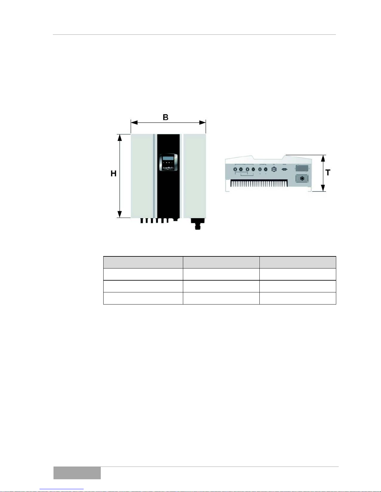
3.1 Dimensions
ES2200 / ES3300
ES4200 / ES5000
H (Height)
[mm]
430
510
W (Width)
[mm]
455
455
D (Depth)
[mm]
190
190
Fig. 3-1 - 1 Dimensions of the photovoltaic solar inverter
Photovoltaic Solar Inverter Series ES
Device Description
ES series
21
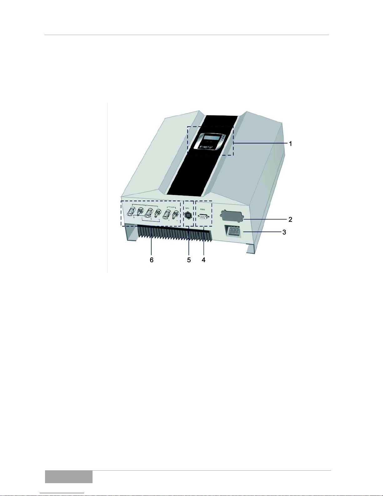
3.2 Display and connections
3.2.1 Display and connections ES2200 / ES3300
1 Front panel with LCD display and LED displays
Operation and display of the operating state of the photovoltaic solar
inverter
2 Data transmission interface to (option)
USB, RS485, floating contact, TCP/IP
3 AC output terminal
AC output for power supply connection
4 Data transmission interface (standard)
RS232
5 Interface for emergency shutdown
EPO
6 Feed for PV module
Plug and holders for the connection of the solar module:
ES2200: 3 connections (1 MPPT)
ES3300: 3 connections (1 MPPT)
Fig. 3-2 - 1 Display and connections ES2200 / ES3300

Photovoltaic Solar Inverter Series ES
Device Description
ES series
22
3.2.2 Display and connections ES4200 / ES5000
1 Front panel with LCD display and LED displays
Operation and display of the operating state of the photovoltaic solar
inverter
2 Data transmission interface (option)
USB, RS485, floating contact, TCP/IP
3 AC output terminal
AC output for power supply connection
4 Data transmission interface (standard)
RS232
5 Interface for emergency shutdown
EPO
6 Feed for PV module
Plug and holders for the connection of the solar module:
ES4200: 3 connections (2 MPPT)
ES5000: 3 connections (2 MPPT)
Fig. 3-2 - 2 Display and connections ES4200 / ES5000
Photovoltaic Solar Inverter Series ES
Assembly
ES series
23
4. Assembly
Before starting the assembly of the photovoltaic solar inverter, take note
of Chapter 2, Safety instructions.
4.1 Assembly of the wall mounting
Before starting the assembly of the photovoltaic solar inverter, take note
of load bearing capacity of the wall.
There is a requirement for a load bearing capacity of at least 300 kg/m3.
Plasterboard or metal stud partition walls are not sufficient.
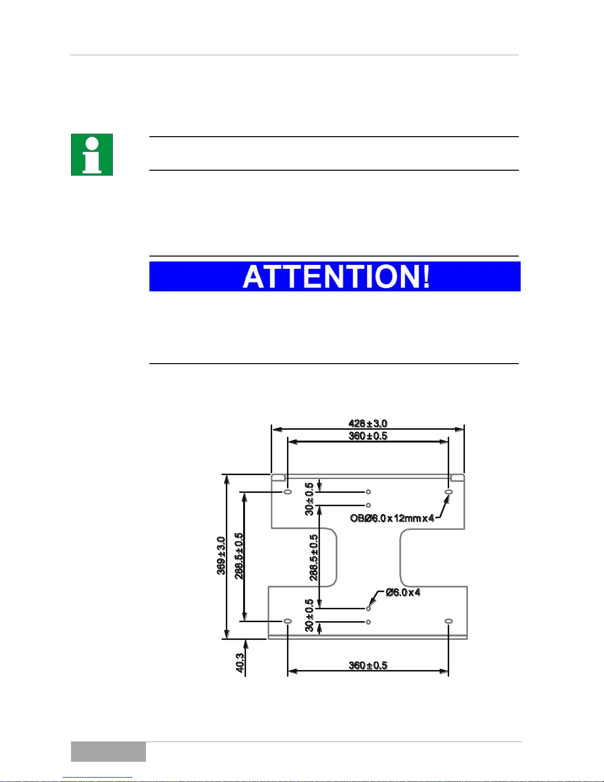
Dimensions for wall mounting
Fig. 4-1 - 1 Wall mounting for photovoltaic solar inverter ES2200 / ES3300
Photovoltaic Solar Inverter Series ES
Assembly
ES series
24
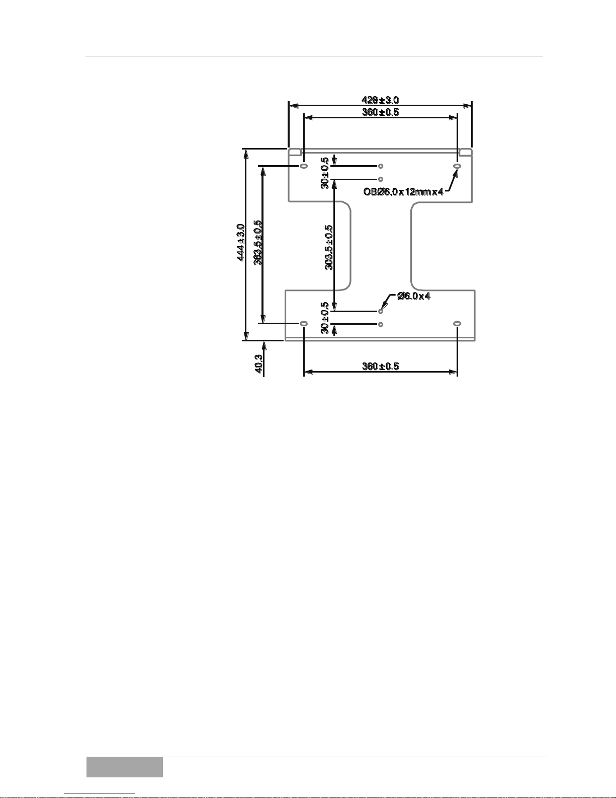
Fig. 4-1 - 2 Wall mounting for photovoltaic solar inverter ES4200 / ES5000
Photovoltaic Solar Inverter Series ES
Assembly
ES series
25
4.2 Ambient conditions for assembly
To guarantee perfect operation and a long service life, assemble the
photovoltaic solar inverter in accordance with the following requirements.
Select the coolest possible location for assembly.
High temperatures hamper the effectiveness and shorten the service
life of the photovoltaic solar inverter. If need be, install an additional
cooling system in the room in which the photovoltaic solar inverter is
assembled.
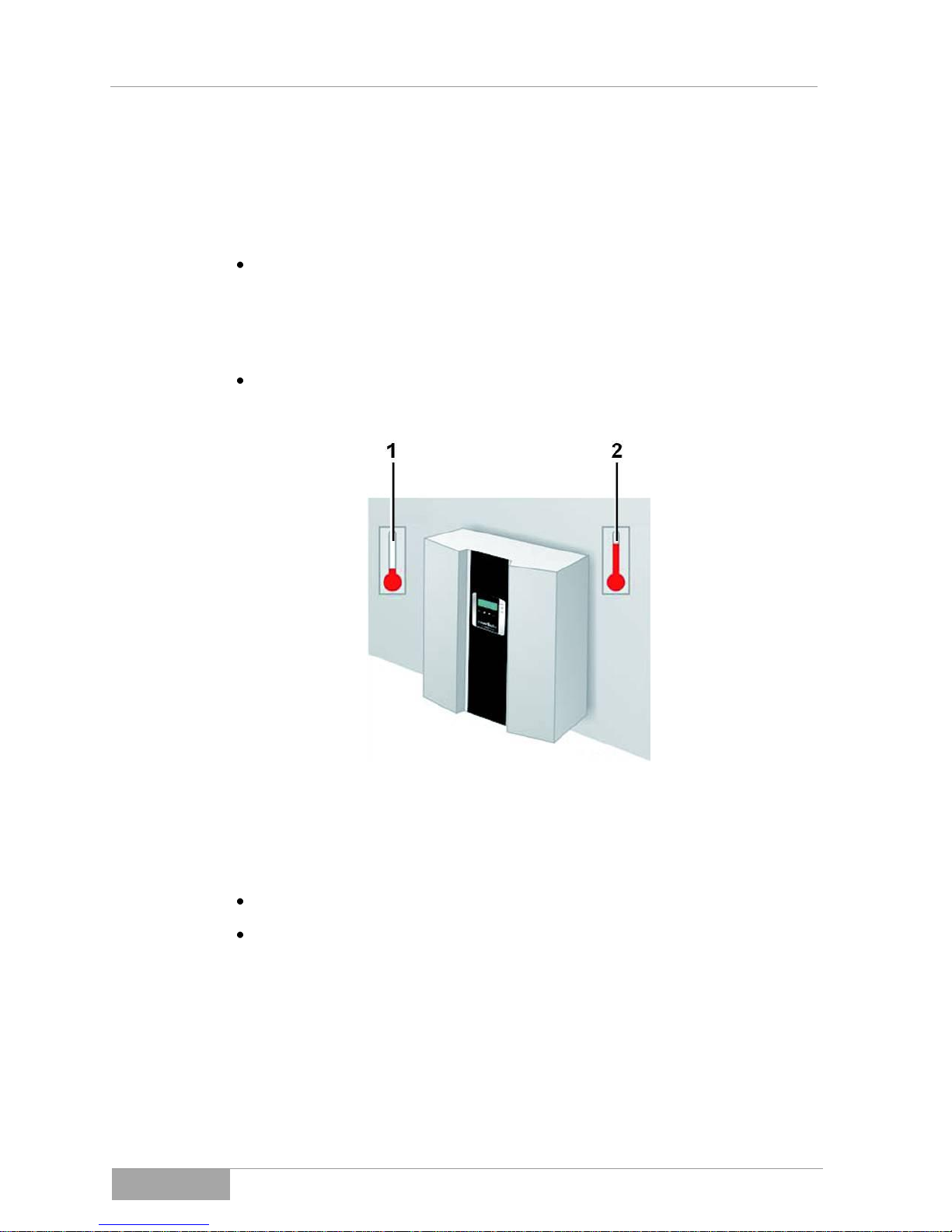
When assembling the photovoltaic solar inverter, the ambient
temperature must be in the range from - 25 °C to + 50 °C.
1 – 25 °C
2 + 50 °C
Fig. 4-2 - 1 Ambient conditions for assembly (temperature)
Relative humidity 0 % to 90 % (without condensation)
The photovoltaic solar inverter may not be exposed to any direct
solar radiation.
Photovoltaic Solar Inverter Series ES
Assembly
ES series
26
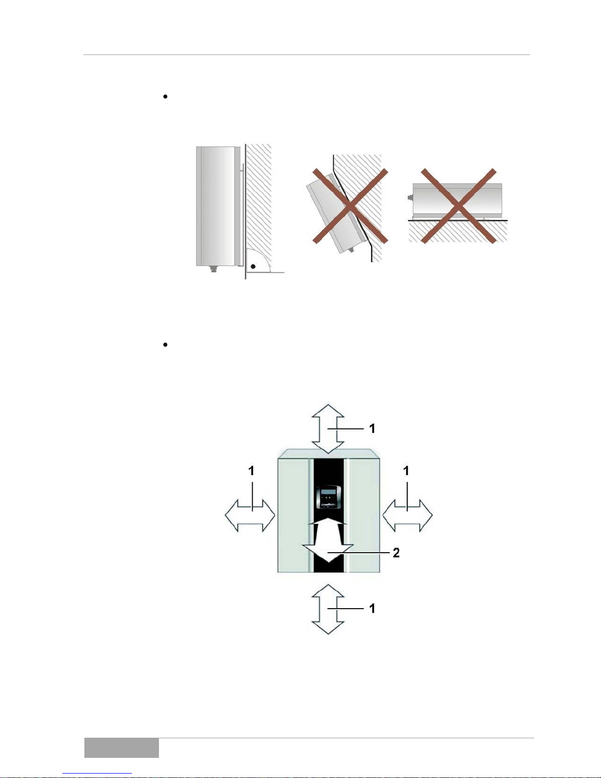
The photovoltaic solar inverter is constructed for vertical assembly.
Never assemble the photovoltaic solar inverter in a horizontal
position and make sure it does not tilt forward if assembled outdoors.
Fig. 4-2 - 2 Ambient conditions for assembly (positioning)
When selecting the assembly location for the photovoltaic solar
inverter, you must ensure that there is sufficient heat dissipation.
The following minimum amounts of free space around the
photovoltaic solar inverter must be maintained:
1 Spacing of at least 20 cm
2 Spacing of at least 5 cm
Fig. 4-2 - 3 Ambient conditions for assembly (spacings)

Photovoltaic Solar Inverter Series ES
Assembly
ES series
27
If the photovoltaic solar inverters are to be assembled above each other, we
recommend offsetting them because of the heat emissions.
1 Spacing of at least 20 cm
Fig. 4-2 - 4 Spacings with offset assembly

Photovoltaic Solar Inverter Series ES
Assembly
ES series
28
If the photovoltaic solar inverters are assembled directly above each other, the
spacings must be adhered to.
1 Spacing of at least 50 cm
Fig. 4-2 - 5 Spacings with inline assembly

Photovoltaic Solar Inverter Series ES
Assembly
ES series
29
4.3 Assembling photovoltaic solar inverters
When lifting heavy loads, take note of the local regulations of the
employers' liability insurance association and if necessary, use several
persons to lift the photovoltaic solar inverter.
Use the supplied wall mounting for the assembly of the photovoltaic solar
inverter.
When selecting the fixing material for vertical assembly using the wallmounting, take into account the weight of the photovoltaic solar inverter.
See Chapter 11, Technical data.
You can use the wall mounting to mark the holes for drilling. If you do not
want to use the wall mounting as a template for the drill holes, please
refer to the dimensions of the wall mounting in Chapter 4.1, Assembly of
the wall-mounting.
The selection of the fixing material is dependent on the characteristics of
the wall. Fixing material is not included in the scope of delivery and must
be supplied by the customer.
When selecting the fixing material, take into account the characteristics
of the wall and the weight of the photovoltaic solar inverter.

Photovoltaic Solar Inverter Series ES
Assembly
ES series
30
To mount the photovoltaic solar inverter, proceed as follows:
1. Mark the positions for the drill holes on the wall.
2. Drill the holes in accordance with the screws you have selected.
3. Screw on the wall mounting.
Fig. 4-3 - 1
4. Hang the photovoltaic solar inverter on the wall mounting. Use the upper
carrier plate so that the photovoltaic solar inverter cannot slip.
5. Check whether the photovoltaic solar inverter is safely attached to the
mounting.
1 Photovoltaic solar inverter
2 Wall
Fig. 4-3 - 2 Assembly of the photovoltaic solar inverter in the wall-mounting

Photovoltaic Solar Inverter Series ES
Electrical Installation
ES series
31
5. Electrical Installation
There is risk of receiving a life-threatening electric shock if you touch live
components.
Only authorised electricians may work on electrical components or
equipment in accordance with electrotechnical rules.
2 Safety Instructions
1 String A
2 String B
3 Data transfer
4 AC output
Fig. 5 - 1 Wiring of the photovoltaic solar inverter
(Example ES4200 / ES5000)
Two strings can be connected with the ES4200 / ES5000 models. Here it
should be ensured that the load on both strings is symmetrical.
This means: One input on the photovoltaic solar inverter can process
50 % of the rated power and may be overloaded by a maximum of 10 %.

Photovoltaic Solar Inverter Series ES
Electrical Installation
ES series
32
5.1 Connecting AC power cable
There is risk of receiving a life-threatening electric shock if you touch live
components.
Only authorised electricians may work on electrical components or
equipment in accordance with electrotechnical rules.
2 Safety Instructions
There is risk of receiving a life-threatening electric shock if a grounding is
missing or is incorrectly connected.
Make sure that the grounding conductor is correctly connected
before you start operating the photovoltaic solar inverter.
Position the cable inlet and screw it to the housing of the
photovoltaic solar inverter.
Connection conditions
Take note of the connection conditions of your mains power supplier.
Pay attention to the locally required country settings on the photovoltaic
solar inverter.
7.2 Country settings, operating mode settings and ID settings
Ground fault circuit breaker
The photovoltaic solar inverter is equipped with an integrated ground
fault circuit breaker.
If an external RCD or FI circuit breaker is required, please use a type B
circuit breaker which triggers above a 100 mA fault current.
Cable line layout
The mains line resistance should not exceed 0.1 Ω as this causes a high
voltage drop and a loss.
Your electricity supplier must calculate the maximum line lengths after
taking the cross section of the line into consideration.
The following cable sizes are recommended for the AC power cables:
Model
Line cross section
ES2200 / ES3300
4 mm2
ES4200 / ES5000
6 mm2

Photovoltaic Solar Inverter Series ES
Electrical Installation
ES series
33
1 String B
2 String A
3 DC connection socket switched off
4 AC connection socket switched off
5 Bi-directional measuring instrument
6 Public supply network
Fig. 5-1 - 1 Overview of the cable lines
To connect the AC cable, please proceed as follows:
Measure the voltage and frequency of the supply mains.
Supply voltage and frequency are country-specific.
In order to separate the photovoltaic solar inverter from the mains power and
the PV modules, a customer-supplied circuit-breaker must be installed for each
circuit.
11.4 Scope of Delivery / (Optional) Accessories
The AC circuit-breaker may not break the grounding.
In order to separate the photovoltaic solar inverter on the AC side, customer-
supplied circuit-breakers must be supplied.
l
ES2200
ES3300
ES4200
ES5000
Circuit-breaker
B10
B16
B20
B25

Photovoltaic Solar Inverter Series ES
Electrical Installation
ES series
34
Even after the circuit-breaker is switched off, individual sub-assemblies
and components of the photovoltaic solar inverter still have a lifethreatening level of voltage charge.
You should make sure that all the sub-assemblies and components of the
photovoltaic solar inverter are voltage-free before starting work.
Fig. 5-1 - 2 Removing cable inlet
Loosen the screws of the cable inlet and remove it.
Fig. 5-1 - 3 Cable inlet
Insert the supply cable through the cable inlet and connect the wires as
indicated on the splitter:

Photovoltaic Solar Inverter Series ES
Electrical Installation
ES series
35
1 PE Grounding conductor (yellow-green)
2 N Neutral
3 L Conductor
Fig. 5-1 - 4 Power cable connection

Photovoltaic Solar Inverter Series ES
Electrical Installation
ES series
36
5.2 Connecting PV module
Before installation, check whether your PV modules are suitable for
operation with your photovoltaic solar inverter.
Not all PV modules are suitable for operation with transformerless
photovoltaic solar inverters.
Check with the PV module manufacturer.
5.2.1 Requirements the PV modules have to meet
The ES4200 / ES5000 photovoltaic solar inverters both have two MPP trackers
(each with approx. 50% of the total output of the inverter). Of these, tracker A
has a connection for up to 2 strings and tracker B for one string.
The ES2200 / ES3300 photovoltaic solar inverters have only one MPP tracker
with a connection for up to 3 strings. Both the maximum DC input voltage of
500 V and the maximum input current may not be exceeded.
The PV module connection cables must be suitable for these connections.
A set of connectors for connecting the line ends of a string is included in the
scope of delivery. The type descriptions for other PV connectors are:
– Connection plug: PV-KST4/6II-UR
– Coupling socket: PV-KBT4/6II-UR
You will find more information online at www.multi-contact.com.

Photovoltaic Solar Inverter Series ES
Electrical Installation
ES series
37
5.2.2 Cabling to the PV module
The photovoltaic solar inverters are equipped with type MC4 PV quick
connecting terminals. These allow up to three of the same strings to be directly
connected with the ES2200 / ES3300 and up to two of the same strings to
tracker A and one string to tracker B with the ES4200 and ES5000.
Please take note of the symmetrical power distribution between tracker A
and B.
The connection of additional strings is possible. These must be externally
connected. We recommend connecting further strings in parallel to the DC
circuit-breaker.
1 PV quick connections
Fig. 5-2-2 - 1
There is risk of receiving a life-threatening electric shock if you touch live
components.
Only authorised electricians may work on electrical components or
equipment in accordance with electrotechnical rules.
2 Safety Instructions
Make sure that the DC circuit breaker is in the "OFF" position before you
connect the PV module.

Photovoltaic Solar Inverter Series ES
Electrical Installation
ES series
38
Attention! Danger of material damage
In determining the required panels in the PV string, please take note of
the following points:
To avoid damage to the photovoltaic solar inverter, make sure that
the output on the PV module is never above 500 VDC.
Make sure that the maximum open circuit voltage UOC of each PV
string is less than 500 VDC. Voltages of over 500 VDC may damage
the photovoltaic solar inverter.
Make sure that the short circuit current of the module is not greater
than the measurement on the photovoltaic solar inverter.
To achieve the maximum energy output from your PV module, make
sure that the voltage does not fall below 150 VDC at maximum UMP
performance or exceed 450 VDC.
Within one tracker, only modules of the same type with the same power
can be used.
Two strings can be connected with the ES4200 / ES5000 models. Here it
should be ensured that the load on both strings is symmetrical.
This means: One input on the photovoltaic solar inverter can process
50% of the rated power and may be overloaded by a maximum of 10%.
To connect the PV module to the photovoltaic solar inverter, proceed as
follows:
1. Check whether the generator terminals have the correct polarity and do not
exceed the maximum voltage for each string.
2. Connect the positive (+) wire of the PV string 1 to the positive quick
connection terminal on the photovoltaic solar inverter.
3. Connect the negative (-) wire of the PV string 1 to the negative quick
connection terminal on the photovoltaic solar inverter.
Repeat steps 2 and 3 for other PV strings.

Photovoltaic Solar Inverter Series ES
Electrical Installation
ES series
39
4. Check whether all wires and contacts have been connected correctly.
5. Cover the unused sockets of the DC input with the supplied protective caps.
6. Start up the photovoltaic solar inverter.
5.2.3 Overview of cabling for the PV module
1 String A
2 String B
3 DC connection socket switched off
Fig. 5.2.3 - 1 ES4200 / ES5000 cabling overview using 4-pin
DC disconnector for each string on tracker A and/or B

Photovoltaic Solar Inverter Series ES
Electrical Installation
ES series
40
1 String A
2 DC connection socket switched off
Fig. 5.2.3 - 2 ES4200 / ES5000 cabling overview in parallel operation
using 2-pin DC disconnector (all modules before the DC
disconnector cabled on one string)
In the case of wiring with one string, you must switch the operating mode in the
configuration to "parallel"; see Chapter
ê 7.2 Country settings, operating mode settings and ID settings
Please note that the ES2200 / ES3300 only have one tracker with connections
for three of the same strings (internally switched in parallel).
If you connect the strings individually, you need a corresponding DC
disconnector for several (4-pin of 6-pin) strings.

Photovoltaic Solar Inverter Series ES
Control Panel
ES series
41
6. Control Panel
1 LCD display
2 LED display
3 Operating keys
Fig. 6 - 1 Control panel
1
LCD display
LINE
Power source
Service operation
Solar cells
Flow chart of the photovoltaic solar inverter in
operation
4-position measurement display

Photovoltaic Solar Inverter Series ES
Control Panel
ES series
42
2
LED display
Red LED lights up constantly - indicates a ground fault or an
isolation fault at the DC input.
Yellow LED lights up constantly - indicates that the supply
(voltage, frequency, etc.) does not correspond to the entered
standard of the photovoltaic solar inverter.
o Green LED lights up constantly - indicates that the
performance of the solar cells is greater than 5 % of the
nominal performance of the photovoltaic solar inverter.
o Green LED blinks - indicates that the performance of the
solar cells is less than 5 % of the nominal performance of
the photovoltaic solar inverter.
3
Operating keys
Confirm a change to the settings of the photovoltaic solar
inverter.
Continue to next page or change the settings of the
photovoltaic solar inverter.
Return to the previous page or change the settings of the
photovoltaic solar inverter.
Special function Log in / Log out.
Log in / Log out
The Log in / Log out function gives you the option of displaying the internal
settings of the photovoltaic solar inverter.
The settings can only be display but not changed.
The following settings are displayed when you operate the Log in / Log out key:
– Bus address
– Country setting
– Operating mode
You can scroll up and down through the settings with the arrow up/arrow down
keys.

Photovoltaic Solar Inverter Series ES
Commissioning
ES series
43
7. Commissioning
There is risk of receiving a life-threatening electric shock if you touch live
components.
Only authorised electricians may work on electrical components or
equipment in accordance with electrotechnical rules.
2 Safety Instructions
Check the following points before you start up the photovoltaic solar
inverter:
The housing is safely screwed in place.
The DC cables (PV strings) are completely connected and unused DC
connection terminals on the bottom of the housing are covered with
safety caps.
The AC cable is connected correctly.
The AC switch is "OFF".

Photovoltaic Solar Inverter Series ES
Commissioning
ES series
44
7.1 Starting device for the first time
Switch on the voltage of the PV string by turning on the DC circuit breaker.
The photovoltaic solar inverter starts automatically when the voltage reaches
120 VDC. All LEDs light up. The following is shown on the LCD display:
Fig. 7-1 - 1 Display A
After 3 seconds, the LCD display changes from Display A to Display B1 (total
feed power) and Display B2 (alarm code).
The green LED blinks to indicate that the output performance of the alternating
current is below 5 % of the nominal performance.
The yellow LED lights up constantly and indicates no power.
Fig. 7-1 - 2 Display B1
Fig. 7-1 - 3 Display B2

Photovoltaic Solar Inverter Series ES
Commissioning
ES series
45
7.2 Country settings, operating mode settings and
ID settings
Make sure before changing the settings that the AC switch is "OFF".
1. Press the key and the key simultaneously for about 5 seconds.
The solar inverter switches to the mode "Settings" and you see the
following display:
2. Press the key to select the appropriate country settings:
dE (Germany), ES (Spain), It (Italy), Fr (France), bE (Belgium),
Pt (Portugal), Gb (Great Britain), CZ (Czech Republic), Gr (Greece),
nL (Netherlands), Au (Austria), EC (User defined).
Incorrect country settings can compromise your mains electricity, cause the
photovoltaic solar inverter to malfunction and lead to the termination of your
authorisation to operate the device.

Photovoltaic Solar Inverter Series ES
Commissioning
ES series
46
3. Press the key to confirm the selection and to proceed to the operating
mode selection.
4. Select either "Standard" or "Parallel" operation with the key.
The display shows:
5. Press the key to confirm the selection and to proceed to the setting
of the ID number.
You can assign an identification number (ID no.) to your photovoltaic
solar inverter in the range from 1 - 200.
You need the ID number to be able to differentiate between different
photovoltaic solar inverters in one system. To do this, each photovoltaic solar
inverter must be assigned a different ID number.
6. Change the ID number in a range of 1 to 200 with the key or the
key.
The display shows:
7. Press the key to save the settings.
The display shows:
The photovoltaic solar inverter goes into normal operating mode automatically
after 2 seconds.

Photovoltaic Solar Inverter Series ES
Commissioning
ES series
47
7.3 Commissioning the photovoltaic solar inverter
Check whether the DC circuit breaker is switched on and set it to "ON" if
necessary.
Set the AC circuit breaker to "ON".
Wait 30 seconds (legally required waiting period).
The LCD display changes between the Displays C1 (total feed power) and
Display C2 (alarm code). The yellow LED lights up and the green LED
blinks.
Fig. 7-3 - 1 Display C1
Fig. 7-3 - 2 Display C2
After 30 seconds, the yellow LED goes off and the green LED blinks again. The
LCD display shows Display D.
Fig. 7-3 - 3 Display D

Photovoltaic Solar Inverter Series ES
Commissioning
ES series
48
After 5 seconds, the LCD display shows Display E. The green LED lights up
constantly.
Fig. 7-3 - 4 Display E
If the photovoltaic solar inverter is working incorrectly, e.g. short circuit, an error
code or the error status will appear on the display.
Fig. 7-3 - 5 Display F
A list of possible error codes with explanations can be found in
Chapter 9, Error codes and explanations.
If the photovoltaic solar inverter was started up completely and successfully,
the LCD display shows Display E.

Photovoltaic Solar Inverter Series ES
Commissioning
ES series
49
7.4 Checking measurement readings and numbers
You can check the measurement readings and numbers determined by the
photovoltaic solar inverter through the LCD display.
Use the and buttons to scroll the displays.
The measurement readings and numbers are shown in the following order
when scrolling downwards:
Fig. 7-4 - 1 Display G - Total feed power
Fig. 7-4 - 2 Display H - Internal temperature of the photovoltaic solar
inverter in °C
Fig. 7-4 - 3 Display I - Temperature of cooling element in °C
Fig. 7-4 - 4 Display J - Internal temperature of the photovoltaic solar
inverter in °F

Photovoltaic Solar Inverter Series ES
Commissioning
ES series
50
Fig. 7-4 – 5 Display K - Temperature of cooling element in °F
Fig. 7-4 - 6 Display L - String A voltage
Fig. 7-4 - 7 Display M - String B voltage
Fig. 7-4 - 8 Display N - String A current
Fig. 7-4 - 9 Display O - String B current

Photovoltaic Solar Inverter Series ES
Commissioning
ES series
51
Fig. 7-4 - 10 Display P - String A output power
Fig. 7-4 - 11 Display Q - String B output power
Fig. 7-4 - 12 Display R - Output voltage of the photovoltaic solar inverter
Fig. 7-4 - 13 Display S - Frequency of the photovoltaic solar inverter
output voltage
Fig. 7-4 - 14 Display T - Output current of the photovoltaic solar inverter

Photovoltaic Solar Inverter Series ES
Commissioning
ES series
52
Fig. 7-4 - 15 Display U - Current feed power
7.5 Operating states of the photovoltaic solar
inverter
The photovoltaic solar inverter starts automatically when the PV panel DC
power is sufficient.
After starting, the photovoltaic solar inverter goes into the following operating
states.
Operating
state
Display on the
LCD display
Explanation
Normal
The photovoltaic solar inverter
is working normally.
When the delivered
performance of the PV panel
is sufficient
(500 VDC > PV >120 VDC), it
supplies the energy to the
mains.
The green LED lights up and
shows that energy is being fed
into the mains.
Standby
If the performance is
insufficient
(60 VDC < PV < 100 VDC),
the photovoltaic solar inverter
switches to standby operation
and searches for a connection
to the mains.
It has only limited power from
the PV module to monitor the
internal system state.

Photovoltaic Solar Inverter Series ES
Commissioning
ES series
53
Operating
state
Display on the
LCD display
Explanation
Error
The internal regulator
continually monitors the
system state and adjusts it.
If the photovoltaic solar
inverter registers malfunctions,
such as mains problems or
internal errors, this is showed
on the display and the red
LED lights up.
EPO
Emergency power off.
The photovoltaic solar inverter
does not receive any power
from the mains in this state.
Shut down
process
No display
If there is too little sunlight, the
photovoltaic solar inverter
automatically ends operation.
It does not receive any power
from the mains. The display
and the LEDs on the control
panel are out of operation.

Photovoltaic Solar Inverter Series ES
Comunication Interfaces
ES series
54
8. Communication Interfaces
You can connect external devices such as PC, Solar-Log or Ethernet (SNMP
card) to the photovoltaic solar inverter to call up data from it. The various
communication interfaces are designed for this.
8.1 Standard communication interface
The standard communication interface for the photovoltaic solar inverter is an
RS232 serial interface (otherwise known as EIA-232).
8.1.1 Settings for the RS232 interface
The RS232 interface is set as follows:
– Baud rate: 9600 bps
– Data length: 8 Bit
– Stop bit 1 Bit
– Parity: None
8.1.2 Pin assignment of the RS232 interface
Pin 3: RS232 Rx
Pin 2: RS232 Tx
Pin 5: GND
Fig. 8-1-2 - 1 Pin assignment:

Photovoltaic Solar Inverter Series ES
Comunication Interfaces
ES series
55
8.2 Solar-LogTM
Our photovoltaic solar inverters are suitable for operation
with Solar-LogTM. Our Sales and Service team
will be pleased to give you information about accessories
and technical details.
8.3 Optional data cards
If you need other interfaces than the standard communication interface, you
can install an optional communication card.
Data cards should only be plugged in when the photovoltaic solar inverter is
switched off. Otherwise, the photovoltaic solar inverter can be seriously
damaged as a result.
8.3.1 Installing communication cards
Fig. 8-1-3 - 1 Open the housing cover
Loosen the screws and open the cover of the housing.

Photovoltaic Solar Inverter Series ES
Comunication Interfaces
ES series
56
Fig. 8-1-3 - 2 Data cable
Insert the data cable through the cable inlet of the cover.
Fig. 8-1-3 - 3 Connect the communication card
Connect the data cable to the communication card.
Fig. 8-1-3 - 4 Insert the communication card
Insert the communication card in the receiver.

Photovoltaic Solar Inverter Series ES
Comunication Interfaces
ES series
57
Fig. 8-1-3 – 5 Fasten the cover
Place the cover back on top and tighten the four screws evenly.
8.3.2 RS485 card
Fig. 8-1-2 - 1 RS485 card
CN1 is intended for the terminating resistor. You can activate the function with
pin 1 - 2 (terminating resistor jumper "ON"); you can deactivate the function
with pin 2 - 3 (terminating resistor jumper "OFF"). CN2 is intended for RS485
and CN3 for remote start-up.
Definition:

Photovoltaic Solar Inverter Series ES
Comunication Interfaces
ES series
58
8.3.3 RS485 interface wiring
DC Several photovoltaic solar inverters with Solar-LogTM
1 Solar inverter address 1
2 Solar inverter address 2
3 Solar inverter address 3
4 Solar inverter address 4
5 Solar-LogTM
6 RS485
7 Terminating resistor jumper "ON"
Fig. 8-3-3 - 1 Solar-LogTM

Photovoltaic Solar Inverter Series ES
Comunication Interfaces
ES series
59
2. Several photovoltaic solar inverters connected to a PC
1 Solar inverter address 1
2 Solar inverter address 2
3 Solar inverter address 3
4 Solar inverter address 4
5 PC
6 RS485/RS232 adapter
7 RS485
8 Terminating resistor jumper "ON"
Fig. 8-3-3 - 2 Connection to the PC

Photovoltaic Solar Inverter Series ES
Comunication Interfaces
ES series
60
DCI Connection to the RS485 card (first photovoltaic solar
inverter)
1 Nothing should be connected here
2 4-core, twisted-pair, screened cable
Fig. 8-3-3 - 3 Connect the RS485 card (first photovoltaic solar inverter)

Photovoltaic Solar Inverter Series ES
Comunication Interfaces
ES series
61
DCII Connection to the RS485 card (several photovoltaic
solar inverters)
1 Free
2 Jumper = OFF
3 Screen to PE
4 4-core, twisted-pair, screened cable
5 Screen, one-sided, to PE
6 4-core, twisted-pair, screened cable
7 Screen, one-sided, to PE
Fig. 8-3-3 - 4 Connect the RS485 card
(several photovoltaic solar inverters)
In the case of several photovoltaic solar inverters, the RS485 bus is looped
through the individual photovoltaic solar inverters. The bus cables D-, D+ and
GND (incoming and outgoing) are connected in parallel to the screw
connectors on the Rs485 card. The screening on the bus cables should each
only be connected at one end with the PE on the photovoltaic solar inverter
housing.

Photovoltaic Solar Inverter Series ES
Comunication Interfaces
ES series
62
8.3.4 USB card
Fig. 8-3-4 - 1 USB card
Definition:
– Compatible USB version 1.0, 1.5 MBit/s
– Compatible HID Version 1.0
Pin assignment for the USB card
1 VCC (+ 5 V)
2 D –
3 D +
4 GND
Fig. 8-3-4 - 2 USB card pin assignment

Photovoltaic Solar Inverter Series ES
Comunication Interfaces
ES series
63
8.3.5 Relay contact card (DCE-B card)
Fig. 8-3-5 - 1 Relay contact card (DCE-B card)
The pin assignment of the 10 pin terminal
1 Pin 1:
One DC input voltage within and one DC
input voltage below the range
2 Pin 2:
At least one DC input above the minimum
limit
3 Pin 3:
All DV input voltage below the minimum
limit
4 Pin 4:
Frequency of the AC output (mains)
outside the tolerance
5 Pin 5:
Isolated operation switched off
6 Pin 6:
Output current of the photovoltaic solar
inverter above the tolerance
7 Pin 7:
The cooling element temperature of the
photovoltaic solar inverter is too high
8 Pin 8:
Common
Fig. 8-3-5 - 2 The pin assignment of the 10 pin terminal

Photovoltaic Solar Inverter Series ES
Comunication Interfaces
ES series
64
Each relay contact can take a load of max 40 VDC / 25 mA.
You can switch the output signal from N.C. (normal close) to N.O. (normal
open) by bridging Pin 1 and 2 or Pin 2 and 3 from JP1-5 with the jumpers.
8.3.6 SNMP card
Fig. 8-3-6 - 1 SNMP card
You will find more information and installation advice in the documents that
accompany the SNMP card.

Photovoltaic Solar Inverter Series ES
Status Diagnosis and Troubleshooting
ES series
65
9. Status Diagnosis and
Troubleshooting
The photovoltaic solar inverter is equipped with a self-diagnosis system that
identifies a large number of possible operating procedures independently and
shows them on the LCD display. This makes it possible to quickly eliminate
technical problems.
Furthermore, a differentiation is possible between
– Service codes concerning installation and
– Service codes that relate internally to the photovoltaic solar inverter
Whenever the self-diagnosis system identifies a particular problem, the
appropriate service code is showed on the LCD display.
The following work may only be performed by trained technical staff
9.1 Error codes and explanations
LCD
display
Description
Explanation
Troubleshooting
Er00
DC_BUS
pre-Charge fail
The device is in soft start
mode, but after 2 seconds,
no stable charging
voltage is determined on
the DC bus.
1. Disconnect all PV (+)- or
PV (-) connections.
2. Wait a few seconds.
3. After the LCD display goes
out, reinsert all the
connections and check it
again.
4. If the error occurs again,
please contact your dealer.
Er03
Inverter voltage
abnormal
The output voltage is not
correct.
Er07
DC_BUS
over-voltage
The internal voltage of the
DC bus is outside the
tolerance.
Er08
DC_BUS
under-voltage

Photovoltaic Solar Inverter Series ES
Status Diagnosis and Troubleshooting
ES series
66
LCD
display
Description
Explanation
Troubleshooting
Er19
DC_BUS
discharge failure
The capacitors of the DC bus
cannot be discharged
correctly.
1. Disconnect all
PV (+)- or PV (-)
connections.
2. Wait a few seconds.
3. After the LCD
display goes out,
restore all the
connections and
check again.
4. If the error occurs
again, please
contact your dealer.
Er22
Output Relay fail
Malfunction on the output relay
of the photovoltaic solar
inverter.
Er24
Output current
sense fail
Error in the output current
reading.
Er25
BOOSTER_A
over-current
The current in the DC mains is
higher than expected.
Er26
BOOSTER_B
over-current
Er29
PV inverter output
DC current over
spec.
DC current at output of
photovoltaic solar inverter is
too high.
Er06
EPO
The photovoltaic solar inverter
is in emergency power off
mode.
5. Detach the
connection at the
EPO connection.
6. If the error occurs
again, please
contact your dealer.
Er09
PV inverter
over-current
Over-current on the AC side.
The current in the AC mains is
higher than expected.
7. Turn off the AC
current switch, check
the peripheral AC
current system
configurations and
the mains
conditions.
8. If the error occurs
again, please
contact your dealer.
Er11
PV inverter
over-load
Over-load on the AC side.
The mains load in the AC
mains is higher than
expected.
Er13
PV inverter
short-circuit
Short circuit on the AC side.
Er14
PV inverter
PLL failure
The photovoltaic solar inverter
is not in phase with the mains
electricity.

Photovoltaic Solar Inverter Series ES
Status Diagnosis and Troubleshooting
ES series
67
LCD
display
Description
Explanation
Troubleshooting
Er10
PV inverter
over temperature
The indoor temperature is
too high.
9. Try to reduce the
surrounding
temperature.
10. Install the photovoltaic
solar inverter in a cooler
place.
11. If the error occurs again,
please contact your
dealer.
Er18
Heat sink
over temperature
The temperature on the
cooling element is too
high.
Er01
Ground fault
The fault current has
reached the authorised
upper limit.
12. Disconnect the feed from
the PV generator and
check the peripheral AC
system.
13. When the reason is
found, reconnect the PV
panel and check the
status of the photovoltaic
solar inverter.
14. If the error occurs again,
please contact your
dealer.
Er17
EEPROM
ERROR on the
control board
EEPROM data is faulty.
15. Please contact your
dealer.

Photovoltaic Solar Inverter Series ES
Status Diagnosis and Troubleshooting
ES series
68
9.2 Mains error alarm codes and explanations
LCD
display
Description
Explanation
Troubleshooting
AL00
Utility Voltage
Over-Voltage
The mains voltage is
higher or lower
than the authorised
amount.
16. Wait 5 minutes. When the
mains supply returns to
normal, the photovoltaic
solar inverter starts up
automatically.
17. Check the mains
connection (cable and
terminals).
18. Make sure the mains
voltage and frequency
meet the requirements.
19. If the error occurs again,
please contact your dealer.
AL01
Utility Voltage
Under-Voltage
AL02
Utility Voltage
Over Frequency
The mains frequency
is higher or lower than
the authorised
amount.
AL03
Utility Voltage
Under Frequency
AL04
BOOSTER_A
Input
Over-Voltage
Under or over-voltage
of the DC input.
20. Disconnect all PV (+)- or
PV (-) connections.
21. Check whether the PV
voltage is under 120 VDV
or above 500 VDC.
22. If the voltage is within this
range and the problem
continues, please contact
your dealer.
AL05
BOOSTER_A
Input
Under-Voltage
AL06
BOOSTER_B
Input
Over-Voltage
AL07
BOOSTER_B
Input
Under-Voltage
AL08
Anti-Islanding
No mains supply or
mains outside the
tolerances.
23. Disconnect all PV (+)- or
PV (-) connections.
24. Check the mains
connection (cable and
terminals).
25. Check the phasing and the
waveform of the mains
supply.
26. If the supply is normal and
the problem persists,
please contact your dealer.
AL13
Phase of
Utility fail
AL14
Waveform of
Utility fail

Photovoltaic Solar Inverter Series ES
Status Diagnosis and Troubleshooting
ES series
69
LCD
display
Description
Explanation
Troubleshooting
AL09
Inverter Voltage
unbalance
The waveform of the
voltage of the
photovoltaic solar
inverter is outside the
tolerance.
27. Shut down the photovoltaic
solar inverter (disconnect
PV generator from the
feed).
28. Restart the photovoltaic
solar inverter (plug the PV
generator into the feed).
29. If the error occurs again,
please contact your dealer.
AL10
GFDI
The fault current of the
grounding wire is too
high.
30. Disconnect the PV
generator from the feed
and check the peripheral
AC system.
31. When the problem is
resolved, reconnect the
PV. Check the status of
the photovoltaic solar
inverter.
32. If the error occurs again,
please contact your dealer.
AL11
Isolation Fault
The insulation
between the PV
connections and the
earth is less than
1 MΩ.
33. Disconnect all PV (+)- or
PV (-) connections.
34. Check the impedance
between PV (+), PV (-)
and the ground (must be
more than 2 MΩ).
35. If the error occurs again,
please contact your dealer.

Photovoltaic Solar Inverter Series ES
Service
ES series
70
10. Service
There are no parts on the photovoltaic solar inverter that have to be maintained
by the customer.
Clean the device at regular intervals with a dry, soft towel to avoid an
accumulation of dust.
In particular, clean the cooling fins on the back of the device.
Service hotline and contact addresses
If unexpected problems occur with the photovoltaic solar inverter or you need
safety information, please contact our service hotline:
Phone no.: 0049 / (0) 741 – 17451-0
Fax no.: 0049 / (0) 741 – 17451-29
If you cannot reach us by phone or fax, we have set up an e-mail contact for
you:
solar-service@effekta.com.
You will also find additional contact addresses online at:
http://www.effekta.com/html/kontakt.html.
You will find the entire spectrum of our services at:
http://www.effekta.com/html/service/html.
You will find an exchange form to download under:
http://www.effekta.com/pdf/Austausch_SolarPhotovoltaik-Wechselrichter.zip.

Photovoltaic Solar Inverter Series ES
Technical Data
ES series
71
11. Technical Data
11.1 Device specifications
ES2200
ES3300
ES4200
ES5000
Photovoltaic
solar inverter
technology
Implementation
Sinusoidal, power source,
high frequency pulse width modulation (PWM)
Isolation method
Execution without isolation transformer
(without galvanic isolation)
Input data
DC
Rated DC
360 VDC
Max. input DC
500 VDC
Work area
120 VDC to 500 VDC**
Max. electricity
per MPP tracker
14.6 A
22 A
(2 x) 14 A
(2 x)
17.65 A
Max. power per
MPP tracker
2200 W
3300 W
2100 W
2650 W
MPPT range
150 VDC to 450 VDC
MPP tracker 1 2
Output data
AC
Nom. AC power
2000 W
3000 W
4000 W
4600 W
Max. AC power
2200 W
3300 W
4200 W
5000 W
Nominal AC
voltage
230 V~
Type of output
connection
Single-phase, mains connection (L, N, PE)
AC voltage range
184 VAC to 264.5 VAC (Base 230 VAC)
Nominal
alternating
current
8.69 A
13 A
17.7 A
20.0 A
Frequency
50/60 Hz, automatic settings
Power factor
>0.99 with nominal alternating current
Distortion factor
of current (sinus
deviation)
Percentage of total harmonious vibration: Below 5 %
of harmonious individual vibration: Below 3 %

Photovoltaic Solar Inverter Series ES
Technical Data
ES series
72
ES2200
ES3300
ES4200
ES5000
Efficiency
data
Max.
implementation
performance
> 96 %
Euro power
> 94 %
CEC power
> 94 %
Standby
consumption
< 7 W
Night-time
consumption
approx. 1 W
Environment
Operating
temperature
- 25 ℃ to + 50 ℃ (- 13 °F to 122 °F)
Humidity
0 to 90 % (without condensation)
Technology
Dimensions
(H x W x D mm)
430 x 455 x 190
510 x 455 x 190
Weight (net)
27 kg
29 kg
Weight (gross)
30.5 kg
32.5 kg
Protective class
IP65 (outdoor area)
Cooling
Convection
AC connection
Screw connection
DC connection
MC4 plug
Communicati
on
Standard
RS232
Optional
USB, RS485, relay contact, SNMP

Photovoltaic Solar Inverter Series ES
Technical Data
ES series
73
ES2200
ES3300
ES4200
ES5000
Control
Panel
LCD display
Input DC voltage / input direct current / input DC power /
output AC voltage / output alternating current / output
frequency / output AC power /
Energy output / internal temperature / cooling element
temperature / status message / error message
LED display
Red:
Grounding fault or
DC input isolation fault
Yellow:
Supply conditions do not
correspond to the
input standard of the
photovoltaic solar inverter
Green:
Performance of solar cells
is above or below 5 % of
the nominal performance
of the
photovoltaic solar inverter
Operating keys
Navigation keys / function key / enter key
Safety
Mains
Over-/ under-voltage, over-/ under-frequency,
grounding fault, DC isolation error, no isolated
operation
Short circuit
DC input:
Reverse pole protection / electronic switching
AC output:
Output relay / electronic switching
EPO
(emergency
power off)
The photovoltaic solar inverter switches off immediately
Overtemperature
≤ 50 °C (122 °F) at full capacity
≥ 50 °C(122 °F) at reduced capacity
Certification
Safety
Europe VDE0126-1-1, EN50178, IEC62103
EMI/EMC
EN 61000-6-1, EN 61000-6-2,
EN 61000-6-3, EN 61000-6-4
** The nominal range should be between 150 VDC and 500 VDC to achieve nominal power.

Photovoltaic Solar Inverter Series ES
Technical Data
ES series
74
11.2 ES2200 / ES3300 Block diagram

Photovoltaic Solar Inverter Series ES
Technical Data
ES series
75
11.3 ES4200 / ES5000 Block Diagram

Photovoltaic Solar Inverter Series ES
Technical Data
ES series
76
11.4 Scope of Delivery / (Optional) Accessories
Check the completeness of the delivery after receiving the goods:
Description
Function / View
Article number
***
1
Photovoltaic solar
inverter
ES2200:
SLWRABSI2K0Wx000
or
ES3300:
SLWRABSI3K0Wx000
or
ES4200:
SLWRABSI4K0Wx000
or
ES5000:
SLWRABSI5K0Wx000
X
1
Wall mounting
Assembly plate for
wall mounting
Upon request
X
3
PV coupling plug
Coupling plug
PV-KST4/6II-UR
PV-KST-4-6.0
X
3
PV coupling bush
Coupling bush PV-KBT4/6II-
UR
PV-KBT-4-6.0
X
3
PV closure cap
for coupling plug
Upon request
X

Photovoltaic Solar Inverter Series ES
Technical Data
ES series
77
Description
Function / View
Article number
***
3
PV closure cap
for coupling bush
Upon request
X 2 Cable inlets
Including assembly material
Upon request
X
IP65 protection
IP65 protection consists of:
Upon request
X
2 covers
Upon request
X
2 washers
Upon request
X
8 screws
Upon request
X
1
DC circuit-breaker
SLDFKNMS32AWX000
O
1
AC circuit-breaker
to be provided by the
customer
*** X = included in standard scope of delivery
O = can be ordered as an option. The EFFEKTA sales team will be pleased to advise you.

Photovoltaic Solar Inverter Series ES
Technical Data
ES series
78
In the following, you will find a list of components that EFFEKTA Regeltechnik GmbH has
approved and tested especially for this photovoltaic solar inverter.
Description
Function / View
Article number
***
Solar-LogTM
Monitoring
Remote diagnostics system
SLZBSLDL21022000
(Solar Log 200 for 1
photovoltaic solar inverter)
SLZBSLDL21050100
(Solar Log 500 up to 10
photovoltaic solar
inverters)
SLZBSLDL21100100
(Solar Log 1000 up to 100
photovoltaic solar
inverters)
Further versions available
on request
O
Software
"EnerSolis“ software for
photovoltaic solar inverter
SWABENERSOLIXX00
O
RS232
connection
RS232 interface connection
cable, approx. 170 cm
(necessary for operating the
software)
M2505
O
RS485 plug-in
card
RS485 expansion card for
photovoltaic solar inverter
SLZBABEK485PX000
O
USB plug-in
card
Expansion card for USB -
SLZBABEKUSBPX000
O

Photovoltaic Solar Inverter Series ES
Technical Data
ES series
79
Description
Function / View
Article number
***
interface
Relay plug-in
card
Relay expansion card for
photovoltaic solar inverter
SLZBABEKRCBPX000
O
SNMP/WEB
plug-in card
SNMP/WEB expansion card for
photovoltaic solar inverter
SLZBABEKWEBPX000
O
*** X = included in standard scope of delivery
O = can be ordered as an option. The EFFEKTA sales team will be pleased to advise you.

Photovoltaic Solar Inverter Series ES
Declaration of Conformity
ES series
80
12. Declaration of Conformity

Photovoltaic Solar Inverter Series ES
ES series
81
Notes

Photovoltaic Solar Inverter Series ES
ES series
82
Notes

Photovoltaic Solar Inverter Series ES
ES series
83
Notes

EFFEKTA Regeltechnik GmbH
Rheinwaldstraße 34
D–78628 Rottweil
Germany
 Loading...