

Effekta ACX11OFS80000RS0, ACX11OFS60000000, ACX11OFS40000RS0, ACX11OFS80000000, ACX11OFS1K000000 Operating Manual
...
UPS
Uninterruptible Power Supply
OFFICE 400-2000
Operating Manual V 1.23
Versions / Article Numbers:
ACX11OFS40000000
ACX11OFS40000RS0
ACX11OFS60000000
ACX11OFS60000RS0
ACX11OFS80000000
ACX11OFS80000RS0
ACX11OFS1K000000
ACX11OFS1K000RS0
ACX11OFS1K500000
ACX11OFS1K500RS0
ACX11OFS2K000000
ACX11OFS2K000RS0
Translation of the original operating manual

UPS: OFFICE 400 - 2000
Legal Notice
OFFICE Series
2
Legal Notice
by EFFEKTA Regeltechnik GmbH
This documentation is solely intended for the operator and his staff. The content
of this documentation (texts, figures, drawings, graphics, plans, etc.) may not be
copied or distributed in part or in full without our written consent, nor can it be
used without authorization for competitive purposes or given made accessible to
third parties.
The publication and copyright of this documentation are retained by:
EFFEKTA Regeltechnik GmbH
Rheinwaldstraße 34
78628 Rottweil, Germany
Phone: + 49 (0) 741 17451 - 0
Fax: + 49 (0) 741 17451 - 22
Email: ups@effekta.com
Internet: www.effekta.com
Operating Manual: V 1.23
Language: English
Release date: 01/2017
We reserve the right to make changes to the design and the system that will improve the system, the production process or the product.

UPS: OFFICE 400 - 2000
Table of Contents
OFFICE Series
3
Table of Contents
1. Introduction ............................................................................................................. 5
1.1 Preface ...................................................................................................................... 5
1.2 Validity ....................................................................................................................... 6
1.3 Storage ...................................................................................................................... 6
1.4 Abbreviations, Terms and Symbols............................................................................ 6
1.5 Information obligation ................................................................................................ 9
1.6 Warranty conditions ................................................................................................. 10
1.7 Limitation of Liability ................................................................................................ 11
2. Safety Instructions ................................................................................................ 12
2.1 Introduction .............................................................................................................. 12
2.2 Proper Use .............................................................................................................. 12
2.3 Prevention of personal injury / property damage ...................................................... 13
2.4 Environmental protection ......................................................................................... 13
2.5 Transport and Storage ............................................................................................. 13
2.6 Positioning ............................................................................................................... 14
2.7 Connection .............................................................................................................. 14
2.8 Operation................................................................................................................. 15
2.9 Working with accumulators ...................................................................................... 16
2.10 Maintenance, service and malfunctions ................................................................... 16
3. UPS device description ......................................................................................... 18
3.1 Topology and operation modes ................................................................................ 18
3.2 UPS device components.......................................................................................... 19
4. Storage and Unpacking ......................................................................................... 24
4.1 Storage of the UPS .................................................................................................. 24
4.2 Transport to the installation site ............................................................................... 24
4.3 Unpacking and positioning of the device .................................................................. 25
5. Installation and Connection of the UPS ............................................................... 26
5.1 Connection of the UPS device ................................................................................. 27
6. Operation of device and service ........................................................................... 30
6.1 Operation and operation modes of the UPS ............................................................. 30
7. Initial operation of the UPS ................................................................................... 34
8. Error messages and support ................................................................................ 35
9. Troubleshooting .................................................................................................... 36
10. Service-Hotline ...................................................................................................... 36

UPS: OFFICE 400 - 2000
Table of Contents
OFFICE Series
4
11. Software ................................................................................................................. 37
12. Maintenance and service....................................................................................... 38
12.1 Measuring the support time (autonomous time) ....................................................... 38
12.2 Replacing components / accumulators ..................................................................... 39
12.3 Maintenance and service contracts .......................................................................... 39
13. Technical Data ................................................................................................ ....... 42
14. Scope of delivery / Accessories ........................................................................... 44
15. Optional accessories ............................................................................................. 45
15.1 Communication adapter SNMP ................................................................................ 45
15.2 External Bypass ....................................................................................................... 45
16. Wear parts .............................................................................................................. 46
17. Declaration of conformity...................................................................................... 47

UPS: OFFICE 400 – 2000
Introduction
OFFICE Series
5
1. Introduction
1.1 Preface
Dear Operator,
This manual is required for the operation of the uninterruptible power supply
described herein.
This operating manual should provide you with support for working responsibly and give basic information about the uninterruptible power supply, namely
on how it works, its application and, in addition, what you should do in the
event of malfunctioning. Furthermore, this operating manual contains instructions for the transport and storage as well as for the handling and installation
of the uninterruptible power supply.
The planning guidelines in this operating manual only relate to special requirements and characteristics of the uninterruptible power supply. All national and local provisions and regulations for electrical installations have to
be adhered to in the installation process. The same applies to the operation of
the device.
The content of this operating manual may change due to technological progress. We have done our best to present the content correctly and clearly. If,
however, we have made errors, we would be grateful if you would let us
know.
We do not assume any liability for errors in this operating manual or any consequences resulting thereof.
The uninterruptible power supply is intended to protect sensitive electronic
systems and equipment from interferences that could occur due to bad electric quality or network failures.
Please read this operating manual carefully and take note particular note of
the safety instructions!
If you have questions about the device, the technical supervisor at your company or our employees will gladly assist you.
Your
EFFEKTA Regeltechnik GmbH

UPS: OFFICE 400 - 2000
Introduction
OFFICE Series
6
1.2 Validity
The descriptions in this operating manual relate solely to the uninterruptible
power supply (UPS) defined in the technical data as a whole or as it refers to
modules, components and individual parts that were developed and built by
EFFEKTA Regeltechnik GmbH ( Chapter 13. Technical Data).
Read this documentation carefully and familiarize yourself with the product
before you start operating it.
1.3 Storage
The operating manual for the device must be stored in the vicinity of the device at all times so it is immediately available if need be.
Pass this manual on to any subsequent users of the product.
1.4 Abbreviations, Terms and Symbols
In this manual, the abbreviation UPS stands for: uninterruptible power supply.
Typically, accumulators are used as energy storage of the UPS-equipment.
Colloquially these are referred to as batteries or rechargeable batteries. A
battery bank is then the term for the centralization of several accumulators
into a group that forms the energy storage.
Danger, Warning, and Attention references are explicitly marked by the respective symbols (pictograms) and must be adhered to without fail. See the
following list and explanations:
Danger / Warning Levels / Notes:
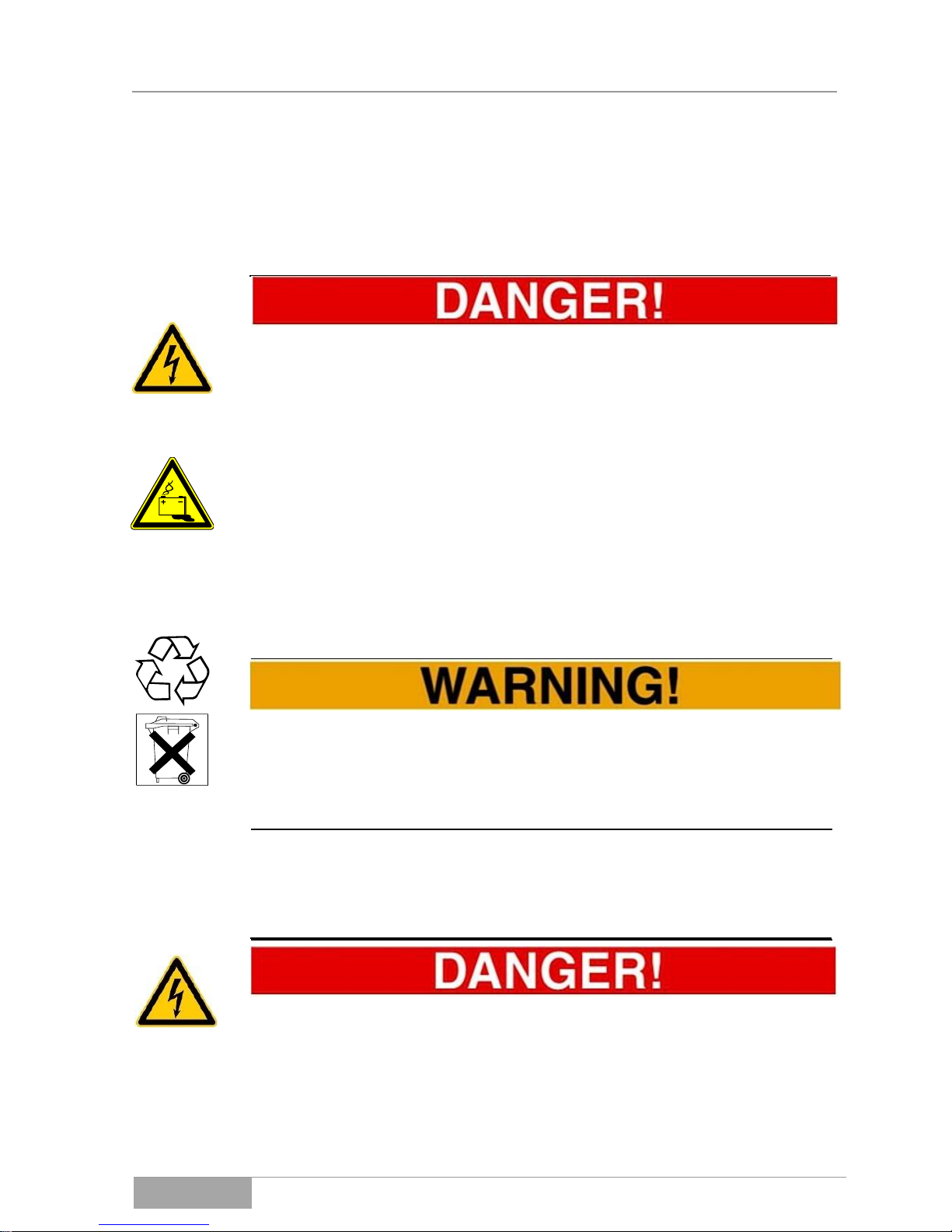
Text that is marked with DANGER! provides a warning about dangers. If accident prevention measures are not taken, these dangers result in serious (irreversible) injuries or even death!

UPS: OFFICE 400 – 2000
Introduction
OFFICE Series
7
Text that is marked with WARNING! provides a warning about hazards. If accident prevention measures are not taken, these hazards may result in seri-
ous (irreversible) injuries or even death!
Text that is marked with CAUTION! provides a warning about hazards. If accident prevention measures are not taken, these dangerous situations can lead
to slight or medium reversible injuries.
Text that is marked with ATTENTION! contains very important instructions for
situations that, if accident prevention measures are not taken, may result in
damage to the product and / or its functions or an object in its vicinity.
This symbol indicates text that contains notices or instructions / comments or
tips.
Warning about danger spots:
General warning about danger spots!
Specific warnings:
Warning about dangerous electrical voltage!

UPS: OFFICE 400 - 2000
Introduction
OFFICE Series
8
Warning about proper handling of accumulators!
Instruction Symbols:
Take note of the provided documentation and/or instructions!
Disconnect before working!
Environmental Symbols:
Identifies instructions for recycling.
Identifies components that are subject to the Electronic Scrap Regulation.
Identifies components or parts that must be disposed of properly. Do not throw
these into the household waste.

UPS: OFFICE 400 – 2000
Introduction
OFFICE Series
9
Text Symbols:
●
This dot marks descriptions of activities that you should carry out.
Requirement that must be fulfilled, for example:
The DC circuit breaker is “OFF”.
–
This dash marks specification lists.
This arrow marks a cross reference.
If a cross reference to another chapter is necessary in the text, this is shortened for clarity.
Example: OM, 2 Safety Instructions
This means: see Operating Manual,
Chapter 2 Safety Instructions.
If the cross reference refers to a page, figure or position number, this information is added at the end of the cross reference.
Example: Fig. 4-4, Pos. 1
This means: see (in this manual in Chapter 4) in
Figure 4, the position number 1.
(3)
Numbers in brackets refer to the positions in the figures.
**
Annotations within the text are marked with ** and explained accordingly.
1.5 Information obligation
This operating manual must be read and understood by all persons and qualified personnel working with this device (this equipment).
This applies, in particular, to maintenance, operating and cleaning personnel
including persons responsible for transportation and/or disposal.
EFFEKTA Regeltechnik GmbH is not liable for damage incurred or caused by
staff who have not been trained or who have been insufficiently trained!

UPS: OFFICE 400 - 2000
Introduction
OFFICE Series
10
1.6 Warranty conditions
The receipt of delivery is considered as the record for the initial purchase and
should be kept in a safe place. It will be necessary for making use of the warranty. If the product is passed on to another user, this user has the right to the
warranty for the remainder of the warranty period. The purchase receipt as
well as this declaration should also be given to the new owner if the device is
passed on.
We guarantee that this device, upon delivery, is in a functional state and technically conforms to the descriptions in the enclosed documentation.
The warranty period for UPS devices corresponds to the minimum periods
stipulated by law.
The warranty ceases to apply in the following cases:
– if the defect is caused by: freight damage, accident, natural disas-
ters, misuse, vandalism;
– in case of improper use, defective maintenance or incorrect repair
by third parties;
– in the event of changes, unauthorized intervention, improper oper-
ation, false installation or other modifications not approved by us;
– in the case of improper use such as the connection of the device
to unsuitable energy sources or unsuitable loads, or in general use
in an unsuitable environment, etc.;
– in the event of failure to follow instructions in the provided docu-
mentation;
– for any defects caused by a lack of due care, e.g. splash water,
etc.;
– in the event that the product is incompatible due to possible tech-
nical innovations or regulations (policies) that occur after the purchase;
– in the case of malfunctions or damage caused by the connection
to incompatible devices or accessories;
– in the event of developments that are related to the normal ageing
process of the product (wear parts);
– in the event of defects that were caused by external fixtures, e.g.
electrical outlets;
– in the event of failure to provide due maintenance and care for the
product;
The warranty period for replaced and/or repaired parts as part of this warranty
expires together with the original warranty for the product.

UPS: OFFICE 400 – 2000
Introduction
OFFICE Series
11
Devices that are supplied without accessories are replaced without accessories. The return of the device is only accepted if it is sent in the original packaging.
Incurred transport costs are generally not included in the warranty.
In general, you shall bear the cost of repair and exchange of the device.
We are not liable for damage or consequential damage, whether directly, un-
intentionally or caused by negligence.
EFFEKTA Regeltechnik GmbH does not provide either explicit or implicit
warranties related to this device and its quality, performance, salability or suitability for a certain purpose. In some countries, the exclusion of implicit warranties is not permitted by law. In this case, the validity of all explicit and implicit warranties is limited to the warranty period. With the expiration of these
periods, all warranties lose their validity. In some countries, a limitation of the
validity period of implicit warranties is not permitted by law so that the aforementioned limitation does not take effect.
1.7 Limitation of Liability
Claims to damage compensation are excluded unless they involve intent or
gross negligence by EFFEKTA Regeltechnik GmbH or its employees. This
does not affect liability according to the Product Liability Act. Under no circumstances are we liable for:
– Claims that third parties make against you due to losses or dam-
age.
– Loss or damage of your records or data or the costs of recovering
this data.
– Subsequent economic damage (including lost profits or savings) or
concomitant damage, even in the event that we were informed of
the possibility of such damage.
Under no circumstances is EFFEKTA Regeltechnik GmbH responsible for
any accidental, indirect, specific, consequential or other damage of any kind
(including, without any limitation, damage related to a loss of profits, interruption of business, loss of business information, or any other losses) that result
from the use of the device or are connected with the device whether they are
based on the contract, damage compensation, negligence, strict liability or
other claims, even if EFFEKTA Regeltechnik GmbH was informed about the
possibility of such damage in advance. This exemption also includes any liability that can result from the claims of third parties against the initial purchaser.

UPS: OFFICE 400 - 2000
Introduction
OFFICE Series
12
In some countries, the exemption or the limitation of concomitant consequential damage is not permitted by law so that the aforementioned declaration
does not enter into force
2. Safety Instructions
2.1 Introduction
The UPS is a device that has been produced according to the rules and regulations of technology for an uninterruptible power supply.
The device is safe when used properly and under consideration of the safety requirements and instructions provided in this operating manual.
2.2 Proper Use
The UPS and its related components may only be used for purposes in accordance with its design – to provide a primary energy source for electrical devices
and a short-term supply from a secondary energy source for electrical devices
which does not exceed the nominal power in its entirety. Any other use is considered improper and can lead to injury of person or property and/or damage to
the device!
The device is not designed for use in
– explosive;
– dusty or humid;
– radioactive or;
– biologically or chemically contaminated atmospheres!
For information about the respective IP protection class of the device please
contact our service centers.
In addition, the device class must be noted with regard to “electromagnetic com-
patibility” (EMC). Radio interference does not occur with Class 1 devices. However, Class 2 devices can cause radio interference in residential areas. In this
case, the operating company may be requested to take appropriate measures!

UPS: OFFICE 400 - 2000
Safety Instructions
OFFICE Series
13
For this reason, please note the information about the device class in the specifications provided (13 Technical Dat).
2.3 Prevention of personal injury / property damage
– Please read this operating manual carefully to familiarize yourself
with the device. Under no circumstances should you ignore the safety information.
– Pay particular attention during the installation and initial operation of
the device.
– Operate this product only in the proper and appropriate manner and
always within the mandated performance parameters (13 Technical Data).
– Only perform maintenance and service work that is described in the
documentation. Observe the required steps. Only use original replacement parts from EFFEKTA Regeltechnik GmbH.
2.4 Environmental protection
Send the product back to EFFEKTA Regeltechnik GmbH after the end of its
service life. We will ensure its environmentally friendly disposal.
2.5 Transport and Storage
The UPS may only be transported to the intended location in the original packaging. The same applies to moves or returns.
The packaging has a very good device-specific protective function. However, all
devices damaged during transport must be checked by EFFEKTA Regeltechnik
GmbH before the initial operation. The same applies in general for any damages
to the device.
Should the device be in storage for more than 4 months, the battery bank of the
UPS device must be charged urgently. For more, see Fehler! Verweisquelle
konnte nicht gefunden werden. Fehler! Verweisquelle konnte nicht gefunden werden..
Due to the possibility of existing energy storage (accumulators) within a UPS,
devices must generally be inspected by EFFEKTA Regeltechnik GmbH or a

UPS: OFFICE 400 - 2000
Safety Instructions
OFFICE Series
14
qualified service center after transportation damages. In the case of transportation damages, there is a high risk that the energy storage units and/or their electrical connections have been affected. As a result, short circuits and/or the leaking of electrolytes cannot be ruled out. For this reason, the unit must be isolated
until an inspection has been performed.
In addition, the device should not be transported or stored upside-down.
2.6 Positioning
Only operate the UPS in well-ventilated rooms, ensuring the specified ambient
temperature range (according to 13 Technical Dat).
The UPS should not be placed in the vicinity of heat sources.
Always take the operating conditions into account when positioning the device.
Maintain the minimum distance to adjacent equipment and walls necessary for
ventilation purposes (see 13 Technical Dat and 5 Installation and Connection of the UPS ensure that the necessary air circulation is provided.
Never place or operate the device in a moist environment. Liquids must, as a
rule, be kept away from the device.
Due to major temperature differences, condensation or dew effects may occur
after the positioning of the UPS. Therefore, an acclimatization period of at least
two hours must be observed before any further steps are taken. Make sure the
temperature adjustment has been completed and that any surfaces with condensation inside and outside the device have completely dried.
Never operate the UPS in a combustible and/or unventilated environment.
2.7 Connection
Always use the connection terminals provided for the purpose of connecting the
UPS.
To avoid electrical hazards, the connection of the unit may only be made under
de-energized conditions.
The PE (protective earth) conductor must be connected without fail. The UPSdevice, as well as the connected loads, must not be used without the PE conductor under any circumstances!

UPS: OFFICE 400 - 2000
Safety Instructions
OFFICE Series
15
The UPS output is supplied with power even in the event of a power outage; according to the provisions included in EN62040-1, the lines and power outlets
supplied by the UPS must be clearly labeled!
In addition, the following points must always be followed when connecting the
UPS:
– Install all connections appropriately and keep the cable length as
short as possible;
– Only use suitable power cables when connection the UPS to the
mains power supply and pay attention to the required current carrying capacity;
– Only use suitable power cables when connecting appliances to the
UPS and pay attention to the required current carrying capacity;
– The safeguarding of any appliance must always be performed imme-
diately in front of an appliance and may never be done centrally in
front of the UPS;
– Never operate any household devices or tools such as e. g. fan heat-
ers, vacuum cleaners, electric drills, hairdryers, toasters, etc. by
means of the UPS;
– Do not connect any appliance to the UPS that could overload the de-
vice;
– In general, only use appropriate tools for the installation.
2.8 Operation
Only qualified personnel are allowed access to the unit and the operation of the
equipment.
It must be kept in mind that the UPS includes an energy storage or is connected
to an external energy storage unit. This means that the UPS outlet can be current-carrying even when the UPS has already been disconnected from the
mains power supply.
Consequently, the UPS output is guaranteed to be de-energized only when the
device has completely shut down and has been disconnected from the mains
power supply.
UPS: OFFICE 400 - 2000
Safety Instructions
OFFICE Series
16
2.9 Working with accumulators
When handling accumulators, there is always a risk of electric shock, burns
and/or chemical burns.
This is why unauthorized personnel should not have access to accumulators.
Accumulators and their circuit points can cause electric shocks.
In the event of a short-circuit of the accumulators, touching the current-carrying
parts can result in severe burns.
Do not place accumulators in the vicinity of heat sources and do not bring them
into contact with open fire. Explosion hazard!
Accumulators should never be opened or destroyed. The electrolyte released
presents a great danger to health and the environment. It could result in chemical burns to skin and eyes; electrolyte is very toxic.
Defective accumulators must be disposed of an environmentally friendly manner!
Never dispose of accumulators with regular household waste!
Local disposal regulations must be observed!
2.10 Maintenance, service and malfunctions
Attention – Risk of electric shock.
Even after switching off the supply with the power button or after disconnecting
the accumulator feed, parts of the UPS can still carry high voltages.

UPS: OFFICE 400 - 2000
Safety Instructions
OFFICE Series
17
The following precautions must be taken when working on the UPS and the accumulators:
– The UPS must first be switched off and disconnected from the mains
power supply and the loads before work on it is begun.
– Remove wristwatches, jewelry and other metallic objects;
– Use only isolated tools;
– Work on live equipment must only be performed by specially trained
personnel. These persons must wear the appropriate personal protective equipment (PPE) at all times;
– The UPS may not be disassembled;
– Work on the accumulators must only be carried out and supervised
by personnel with the required expertise concerning safety regulations;
– Unauthorized persons must be kept away from the UPS and the ac-
cumulators.

UPS: OFFICE 400 - 2000
Device Description
OFFICE Series
18
3. UPS device description
Sensitive loads require comprehensive protection against supply disruption.
This includes: temporary mains failure, mains voltage fluctuations, mains voltage peaks, frequency changes, etc. The uninterruptible power supply unit is intended to support mains-supplied, sensitive electronic devices such as: computers, workstations, cash registers, operation-critical instruments, telecommunication devices, process control systems, etc. against supply disruptions. In doing
so, the UPS supervises the above mentioned network sizes and supports the
loads in critical moments. The support time, or autonomous duration, is dependent on the size of the installed or adapted energy storage (accumulator).
3.1 Topology and operation modes
In the OFFICE series, there is a so-called “LINE INTERACTIVE” or “OFFLINE”
setting. This is identified in that the load is directly supplied by the mains power
supply in standard mode (Mains operation) (see Fig. 3-1). Light mains voltage
fluctuations are then equalized by the AVR (AUTOMATIC VOLTAGE REGULATION) so that a load operation is ensured to always remain in the standard
mains voltage range.
Fig. 3-1 Block diagram or setup of the OFFICE series.
In the event of a massive mains fault, the switching unit turns on in the Inverter
mode (Inverter operation or autonomous mode). The loads will only be operated
directly via the inverter for the duration of the fault. The inverter draws the necessary power from the accumulator during this autonomous period. Once the
mains fault / mains failure has passed, the switching unit switches again to
mains operation.
As long as the device it connected to the mains power supply, the charging unit
of the accumulator is being charged (Charging mode). The maximal autonomous duration for the UPS is dependent on both the charging status and the capacity of the accumulator. Please see the section on technical data in this operating manual for details.

UPS: OFFICE 400 - 2000
Device Description
OFFICE Series
19
3.2 UPS device components
The entire device series is integrated in a plastic case. All components of the
device for operation are located on the front panel of the device, and all components for the connection are distributed on the backside of the device (see the
following figures). The front panels of the devices are the same for all versions.
The front panel of the device also serves as an operation panel and is presented here as representative of all units:
Front panel of device (Operating panel):
(1) Device indicator (DISPLAY)
(2) Power switch On/Off
The backsides of the devices of the OFFICE device series differ in the respective
version and power class according to the following figures. In summary, the power
ranges (400 – 800 VA, 1000 – 2000 VA) are accommodated, each in a housing size.
Only the design variants between the serial interfaces (RS variants) or the overvoltage protection (LSP variants) are possible within a device.
Illustration of the backside of the device: 400, 600, 800 VA

UPS: OFFICE 400 - 2000
Device Description
OFFICE Series
20
Illustration of the backside of the device: 1000, 1500 VA (1000VA without Fan)
Illustration of the backside of the device: 2000 VA
Device model (LSP):
(A) Device outlet port (C13);
(B) Power input (C14);
(D) USB port;
(E) Overvoltage protection (LSP);
(F) Unit fan (1500/2000VA);
Geräteausführung (RS):
(A) Device outlet port (C13);
(B) Power input (C14);
(C) Serial port (RS);
(D) USB port;
(F) Unit fan (1500/2000VA);
UPS: OFFICE 400 - 2000
Device Description
OFFICE Series
21
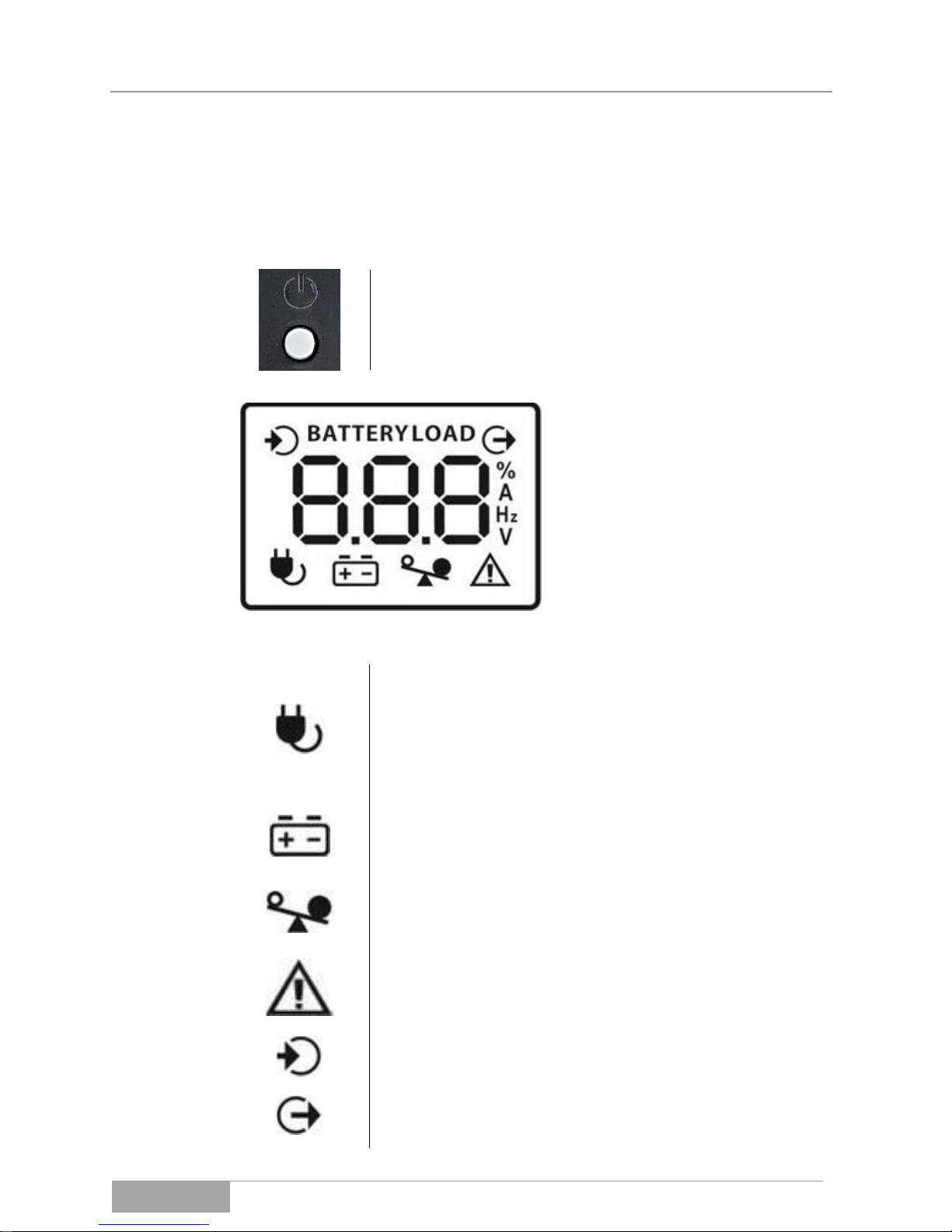
3.2.1 The operation panel (front panel of device)
In this device, the control panel is reduced to the power switch and the device
display (TOUCH):
Power switch: for switching the UPS on and off. If the
UPS is already connected to the mains power, the unit
starts up automatically and initializes. Only the UPS device outlet port remains switched off.
Device display (TOUCH) for the
clear presentation of all status
data.
During operation, the operation
parameters can be requested by
touching the displays. Generally,
the display remains on the information selected last.
Meaning of the individual display symbols:
Mains operation mode: appears when the device is connected to the mains supply.
The symbol turns off in the event of mains fault or failure.
Should the voltage regulation (AVR) become active, the
symbol blinks on the display.
Autonomous mode: appears when the device is in the inverter mode. If the battary capacity is low, this symbol
blinks.
Overload display: appears and blinks when the unit is
overloaded from the output side.
Device or system error: appears when a device error internally or a system error (e.g. overload in the output) occurs.
Display of the UPS input data (e.g. power supply in volts).
Display of the UPS output data (e.g. load voltage in volts
or the load in %).

UPS: OFFICE 400 - 2000
Device Description
OFFICE Series
22
3.2.1 Auditory operation, warning and alarm signal
In addition to the information on the display, some operation, warning and alarm signals are provided acoustically via the integrated signaler (BUZZER).
3.2.2 The connection panel (back panel of device)
Device port: RS232 port for the exchange of
device data and the signals for shutting down
sensitive loads (PC, SHUT DOWN). If the serial port is used, the USB port remains inactive.
The serial port is only available in the RS device variants.
Device port: USB port for the exchange of device data and the signals for shutting down
sensitive loads (PC, SHUT DOWN). If the
USB port is used, the serial port remains inactive.
Overvoltage protection module: Data and telephone lines can be wired through here to
safeguard against overvoltage (IN / OUT).
Power input (cold device plug C14) with integrated input fuse in the compartment.

UPS: OFFICE 400 - 2000
Device Description
OFFICE Series
23
UPS output (sockets C13). With these, up to
six separate loads can be connected; mind
the load values when connecting.
3.2.1 Name plate (Device identification)
exemplary fig.
UPS device identification. The following information is on the name plate:
– model name;
– data for connected load values;
– articel number;
– the CE and ROHS markings and
the serial number for the device;
– manufacturer’s address;
As a basic principle, compare the name plate on the device and the present operating manual for conformity. As a result, this bars improper use of the operation manual and the UPS.

UPS: OFFICE 400 - 2000
Storage and Unpacking
OFFICE Series
24
4. Storage and Unpacking
4.1 Storage of the UPS
If the UPS is to be put in storage after delivery, it is imperative to observe the
following instructions:
– Always leave the device and accessories in the original packaging;
– Never store the UPS upside-down;
– The recommended storage temperature should be between 10 –
25°C. The maximum temperature values may never be exceeded
(see also 13 Technical data);
– The delivered goods must also be protected against moisture. The
device must therefore be stored in a dry area;
– If the storage period exceeds four months, the UPS must be con-
nected with the mains power supply for approximately 24 hours to
avoid a total discharge of the accumulators, which would result in irreversible damage to the accumulators.
4.2 Transport to the installation site
As the point of delivery is usually not the point of installation, the equipment has
to be transported to the installation site. Please follow these instructions for the
transport of the UPS:
– Always transport the delivery in the original packaging as close as
possible to the installation site;
– Always transport the UPS in the specified transport position. Do not
transport the device upside-down;
– Also mind the specified center of gravity when transporting the de-
vice;
– There is always a general risk of tipping or tilting with devices where
the center of gravity is located in a high position;

UPS: OFFICE 400 - 2000
Storage and Unpacking
OFFICE Series
25
4.3 Unpacking and positioning of the device
Remove the packaging at the installation site with the utmost care to avoid
causing any possible damage to the device and the packaging material.
Check the scope of delivery (see 14 Scope of delivery / ).
Check all packaging materials to ensure that no items are missing.
Inspect the appearance of the UPS after unpacking to see if any visible damage
incurred during transportation. Do not turn on the unit if you detect any damages
or if any parts are missing, but rather notify the carrier and dealer immediately.
The shipping materials are recyclable. After unpacking, save them for later use
or dispose of them appropriately.

UPS: OFFICE 400 - 2000
Installation and
Connection
OFFICE Series
26
5. Installation and Connection of the UPS
All critical values listed in the technical specifications concerning ambient and
operating conditions must be met to ensure proper operation of the UPS.
The UPS must be installed in a well-ventilated area, far from water, flammable
gases and corrosive agents.
In general, the following rules apply for the installation of the device:
– The device may only be mounted on a solid, weight bearing and hori-
zontal surface;
– Ensure a proper vertical installation position, as specified;
– The UPS may only be installed in a clean, dry environment free of
dust;
– In addition, air exchange according to EN62040-1, appendix M for
devices with accumulators must be ensured;
Fig. 5-1 Installation as standing device for the entire OFFICE series.
In addition, make sure that the ventilation channels of the UPS are not blocked
and that there is sufficient clearance between the device and other equipment,
furniture and walls to allow the device to cool. The following minimum distances
are recommended as clearance space for the OFFICE series. If there is a
forced ventilation, the clearance spaces can be reduced slightly:
Fig. 5-2 Minimum distance and maintenance space surrounding the UPS.

UPS: OFFICE 400 - 2000
Installation and
Connection
OFFICE Series
27
5.1 Connection of the UPS device
The OFFICE model is equipped with plug connection. With this, the UPS can be
connected with the standard wall socket (power supply) via the power cable provided (Schuko/C13).
Provided the UPS has been connected to the mains power supply, it will start up
automatically and switch to the charging mode. An indication on the display follows. The UPS output is not active.
Ensure that the wall socket is properly secured and that the PE connection is
available.
Additionally, the loads can, for example, be connected by means of an appropriate cable connection.
Attention here must also be paid that the PE connection and the proper fuse
protection for the loads are available.

UPS: OFFICE 400 - 2000
Installation and
Connection
OFFICE Series
28
If a permanent connection of the UPS should be made, please pay attention to
the following connection diagram.
Fig. 5-3 Connection diagram of the UPS to the network and the loads.
(S)
Circuit breaker or fuse 10A;
(1)
Wire cross-section of the connection cable 0.75 mm²;
Grounding!
It is implicit to connect the protective conductor here and to maintain the loop
resistance all the way to the last load.
It is likewise possible to secure the loads separately against over and fault currents and to directly ground them.
Always pay attention to the correct polarity between input and output for the
UPS.
If the UPS is in the midst of an emergency stop circuit, it must be observed that
the UPS output is not completely currentless after the emergency stop circuit
operation. The loads will continue to be supplied by means of the duration of the
UPS autonomy time.
5.1.1 Connection of the device port RS232 (Communication interface)
The serial port RS232 serves to connect the UPS with a PC or rather the application (software) installed on it
The connection is to be established by a standard serial cable. The configuration is as follows (not listed pins are not assigned):
PC RS232:
USV RS232:
Function:
Pin 2
Pin 2
Tx USV, Rx PC
Pin 3
Pin 3
Rx USV, Tx PC
Pin 5
Pin 5
GND
Fig. 5-4 RS232 Connecting a device to the UPS (SubD 9pole, female).

UPS: OFFICE 400 - 2000
Installation and
Connection
OFFICE Series
29
The serial port RS232 of the UPS works with the following interface parameters:
– Data rate: 2400 Baud;
– Data bits: 8;
– Stop bits: 1;
– Parity bit: none;
This interface supports the complete “Mega Tec Extended” protocol (version Au-
gust 2000). Please use the accompanying software to check the connection.
5.1.2 Connection of the USB device port USB (Communication port)
Please use the USB cable provided or an alternative cable (Type A to type B) to connect the
USB port and connect the UPS to a PC or hub
with this.
The USB port is a plug and play connection.
Additional actions are not necessary. Please
use the accompanying software to check the
connection.
5.1.3 Connection of the overvoltage module
A data or telephone line can be protected against overvoltage, e.g. against lightening, via the built-in overvoltage protection module (RJ11).
Fig. 5-5 Connection of the data and telephone line against overvoltage.
Using the telephone line as an example, insert the incoming telephone line into
the “IN” jack and the continuative line of the telephone into the “OUT” jack. This
loops and secures the telephone line through the overvoltage protection module. The same can be performed with a data line in order to protect it. Please
take the level of protection from 13 Technical Dat in this manual.
IN
OUT
UPS: OFFICE 400 - 2000
Operation and Service
OFFICE Series
30
6. Operation of device and service
Due to the comprehensive protective functions which the device performs regarding the loads, the UPS runs completely automatically. This reduces the operation of the device to a few steps.
In general, the operating personnel should inform affected employees (keyword:
consumer network) about any scheduled tasks concerning the UPS system.
Have the status and error messages listed in chapter 8 ready to facilitate the immediate interpretation of the operation display and possibly occurring errors.
6.1 Operation and operation modes of the UPS
As a rule, the switching on or starting up and shutting down of the system is
done by the operating personnel.
The operator of the UPS-system must always adhere to the instructions in this
operating manual. Only the operator can perform the following actions and must
always exercise particular care:
– Switching on and off the UPS;
– Reading the display messages and interpreting the acoustic warning
signals;
– Switching from standard mode to autonomous mode and vice versa.
In addition, data can be exchanged with the UPS via the communication interface(s), but this data exchange is not imperative for general operation. Therefore, particular care and diligence are also required here as the UPS can, for example, by shut down by the software.
6.1.1 Switching on the UPS, Charging mode
If the UPS is connected to the network, the device switches on automatically and begins with
the initialization. The display shown here occurs for 4-5 seconds.

UPS: OFFICE 400 - 2000
Operation and Service
OFFICE Series
31
Then the device automatically switches to the
charging mode. The display shown here occurs when the UPS output is not switched on.
An acoustic message does not occur in this
startup process of the UPS.
In any event, it is beneficial to keep the device in the charging mode for a few
hours in order to reach the accumulator’s complete loading status before the
UPS is switched on and assumes its support function.
6.1.2 Changing the display informationen
As soon as the UPS is either operating on the network or generally switched on, additional device or
load information can be accessed by touching the
display. The selected information is preserved
provided the device operating mode has not been
changed
In the event that the background lighting of the
display turns off, this can be reactivated by touching the display.
6.1.3 Switching the UPS on (network connection already available)
Switching on is performed with the on-off
switch. The display changes to the screen pictured here. The UPS is now in mains opera-
tion mode.
The UPS output is switched on, the loads are now being supplied and supported. In addition, the charging unit continues to be active until the accumulator
is completely charged.
6.1.4 Autonomous mode of the UPS
The UPS is forced into the autonomous
mode by an interruption in the network con-
nection. The display changes to the screen
pictured here.

UPS: OFFICE 400 - 2000
Operation and Service
OFFICE Series
32
The autonomous mode is supported by an
acoustic beeping of about a 1 second duration
and an 8 second pause.
The UPS output remains switched on, the loads will continue to be supplied for
the duration of the autonomy time.
The charging of the accumulator can be observed. For this, the appropriate display page
must be selected (TOUCH) so the information
shown here can appear.
Generally, a low battery level can also be recognized by a blinking battery symbol. An acoustic beeping of a roughly one second duration and 1 second pause
signalizes when the autonomous mode is about to end.
6.1.5 Switching off the UPS
Switching off occurs by means of activating
the on/off switch again. The device switches
the UPS outlet on whereby the charging unit
remains. The display changed to the image
pictured here.
In the event of a complete shutdown of the device, the UPS must also be separated from the mains power supply.
6.1.6 Direct switching on of the autonomous mode (COLD START)
Without the power connection, the UPS is
switched on and started by activating the onoff switch and changes directly to the autono-
mous mode. The display shows the screen
pictured here.
The starting process is supported here by a
sustained beep (3-4 s).
The UPS output is switched on, and the loads are supplied for the duration of
the autonomy time. After re-activating the on-off switch, the UPS shuts down
completely again.
This operation mode is frequently used to determine the remaining autonomy
duration.

UPS: OFFICE 400 - 2000
Operation and Service
OFFICE Series
33
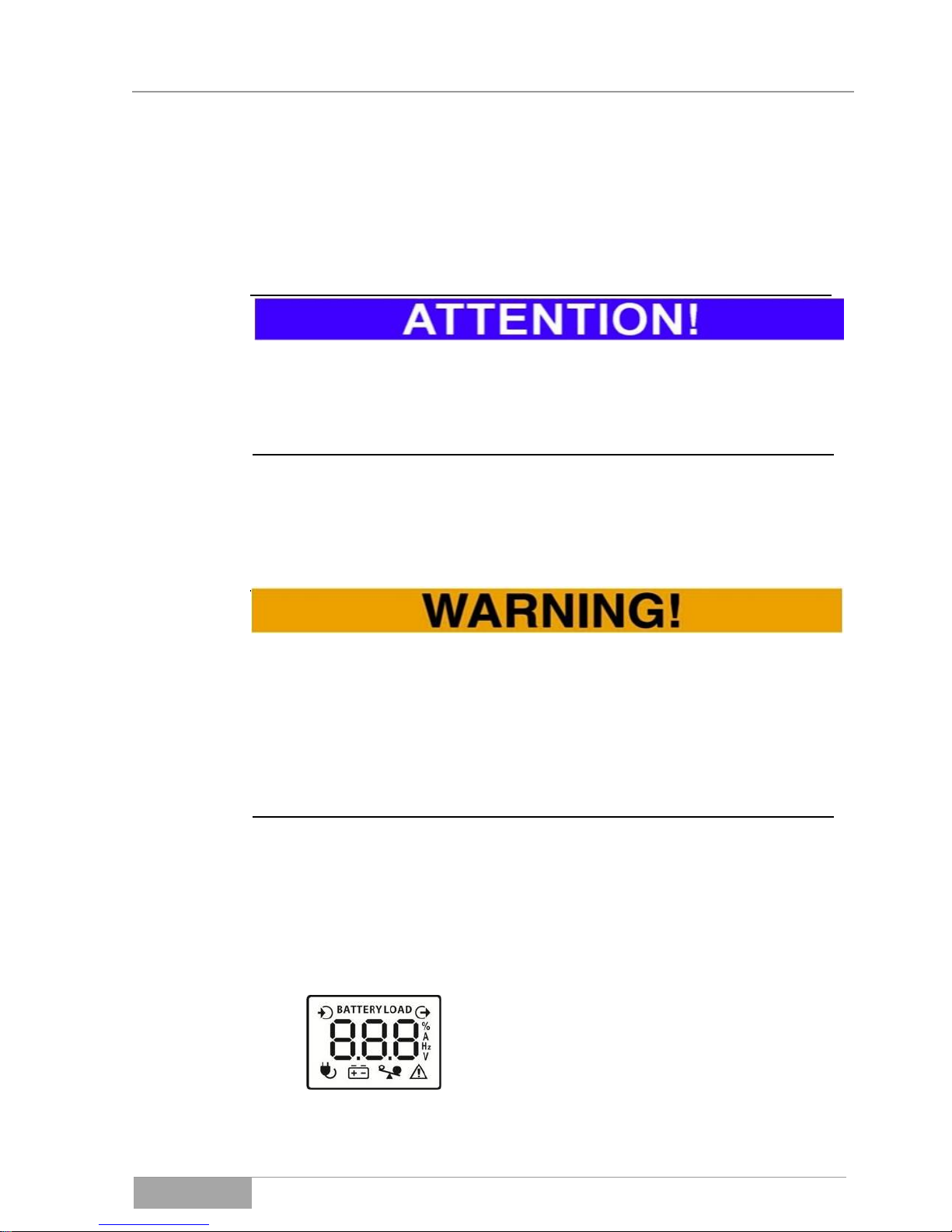
6.1.7 Overload mode of the UPS
If the UPS is overloaded from the output side,
the device displays its status with the blinking
overload symbol ( ). The loads will be further supplied temporarily depending on the
overload. The display shown here occurs
(here, for example, 112 % load).
During the overload mode, a rapid beeping occurs (0.5 s interval).
In the event of a subsequent error, a continuous acoustic signal occurs.
6.1.8 Error mode of the UPS
When the UPS switches to the error mode,
e.g. due to overload, the device switches the
output off. The loads are no longer supplied;
the display shown here occurs.
In the event of an error mode, a continuous
acoustic signal occurs.
A return from the error mode is not automatically carried out by the UPS. It is
necessary here to switch the device off or on again. However, this can only be
carried out if the error source that occurred has first been removed.

USV: OFFICE 400 - 2000
Inbetriebnahme
OFFICE Series
34
7. Initial operation of the UPS
The initial operation generally requires that all previous chapters of this manual
have already been successfully read or processed.
Additionally, check that all connected loads are switched off.
The initial operation of UPS devices is exclusively reserved for accredited per-
sonnel.
Please conduct the initial operation in the following order:
Connect the UPS to the mains power supply;
Then the UPS starts up automatically and switches to the charging mode. The
UPS output remains off. The corresponding image occurs in the display. Now
switch the UPS on and, from here, the UPS switches to the standard mode; the
UPS output is now active;
Check all the status information on the display;
Turn on the loads individually, under the observation of the indicated
power levels;
Briefly test the autonomous mode similarly under the observation of
the power levels and status information;
The UPS can be left in the mains operation (standard mode), the
loads are secured via the UPS;
Switching off the UPS occurs in the reverse order.
Should errors occur during the initial connection, these must first be analyzed
and removed before the initial operation can be continued.

UPS: OFFICE 400 - 2000
Error Messages
OFFICE Series
35
8. Error messages and support
In the event the UPS device is not working properly, please first check the operation information on the operation unit.
Please try to localize the problem with the aid of the following table:
Problem/Display:
Possible cause:
Corrective actions:
The UPS is not starting although it is
connected to the
network.
The power cord is not
functional or not
properly plugged in.
Check the power cord or network connection.
Short circuit on the
UPS output.
Remove the loads and restart the UPS.
Overload on the UPS
output.
Remove the loads and restart the UPS.
Overcharging the internal battery bank.
Immediately contact the service hotline.
Degenerated or completely discharged battery bank.
Have qualified personnel change the
accumulator and check the charging
unit.
Output voltage error.
Immediately contact the service hotline.
Device internal overtemperature.
Switch the UPS off for some time or reduce the load or see to a lower ambient
temperature.
The autonomy time
is shorter than indicated.
Either the accumulator
was not completely
loaded or the battery is
degenerate.
Charge the accumulator for at least 12h
and measure the autonomy time again.
If this was unsuccessful, exchange the
battery.
Never try to start up the UPS when there is an error status. Always remove the
error source first and then switch the device on again.

UPS: OFFICE 400 - 2000
Error Messages
OFFICE Series
36
9. Troubleshooting
Over the course of time, failures or malfunctions of the UPS, the accumulator or
their surroundings can arise. In this event, please contact our customer service
(service hotline) as soon as possible.
When contacting the service center, please provide the following information to
ensure swift resolution:
– Model number, serial number and configuration of the device;
– Progress of the issue and date on which the it first occurred
– Control panel LCD/LED display information (status or warning or
alarm messages);
– Condition of the mains power supply, load condition, environment
conditions, temperature and moisture, ventilation conditions;
– Information of the condition, such as the age, of the accumulator;
Most importantly, name the respective qualified contact persons for the clarification of the issue and its resolution.
10. Service-Hotline
Should you encounter any general problems or require any information regarding safety, please contact our service hotline:
Phone: 0049 / (0) 741 – 17451-52
Fax: 0049 / (0) 741 – 17451-29
You can also reach us via email at:
kundendienst@effekta.com
In addition, you can contact the relevant department or branch office directly as
listed on our website:
http://www.effekta.com

USV: OFFICE 400 - 2000
Software
OFFICE Series
37
11. Software
The UPS management software runs as a client / server application for heterogeneous networks or on a local computer.
It works on any common platform (Win, Linux, UNIX).
Remote access to the UPS and its data is possible and recordable.
The software shows all relevant UPS data such as the accumulator condition,
temperature, condition of the mains power supply, etc. in a clear graphic interface.
Malfunctioning of the system can be reported easily via e-mail, mobile phone or
fax.
The range of services can roughly be summarized as follows:
– The availability for Windows 95/98/2000/NT/XP/Vista/Win7, Novell,
Linux etc.;
– Local or network SHUTDOWN;
– The integrated SNMP-sub-agent;
– The graphic interface with all UPS information;
– Event-based sending of network news;
– Event-based sending of emails and text messages;
– Recording (LOGGING) all UPS status data and measurements;
– The timetable (SCHEDULER) for time controlled execution of func-
tions such as REBOOT, SHUTDOWN, etc.;
A software package is included in the scope of delivery of the device. Please
see the respective manual on the CD for additional information on the performance, installation, use, etc.

UPS: OFFICE 400 - 2000
Maintenance and
Service
OFFICE Series
38
12. Maintenance and service
You can expect a long service life and interference-free operation from this
product. The service life and reliability of the UPS is greatly dependent on the
conditions of its environment. The ambient temperature and humidity in the vicinity of the device must remain within the specified range. In addition, the area
around the UPS should preferably be kept clean and free of dust.
At an ideal ambient temperature of approximately 20-15°C, the service life of an
accumulator is typically about 4 years. Through the use of special accumulators,
the service life can be significantly increased (up to 8 years).
It should be regularly checked (6-12 months) if the remaining autonomy time
(back-up time) is sufficient for the intended purposes. Should this no longer be
the case, the accumulators will have to be replaced.
.
12.1 Measuring the support time (autonomous time)
Before beginning with this procedure, it is obligatory that all open data files must
be secured. Also, inform all concerned employees of your intentions.
There are essentially two methods to measure the support time.
Method A is suitable for measuring the actual back-up duration whereby the
loads are required to be currentless at the end of the autonomy time. For this
purpose, force the UPS into the autonomous mode and measure the time until it
automatically shuts down.
Method B allows for the determination of the remaining capacity after a defined
back-up period. Also for this method, first force the UPS into the autonomous
mode for a specific duration. In returning to the mains operation mode, note the
remaining capacity. Then calculate the autonomy duration through an estimation
(linear).
Please remember that after measuring the autonomous period, the accumulator
may be discharged. This means that the UPS device must remain in standard
mode for several hours (min. 6 h) to recharge the accumulator bank accordingly,
before this is again up to 70 % operational (capable of supporting).

UPS: OFFICE 400 - 2000
Maintenance and
Service
OFFICE Series
39
If the backup-time is not measured due to local conditions or regulations, we
recommend the prophylactic replacement of the accumulators every other year
to avoid any risk of an insufficient autonomous period (back-up time) caused by
degenerated accumulators.
If a defective accumulator is detected within the UPS, an acoustic signal is sent
(Beeping at intervals of 2 s).
In addition, the fans and ventilation ducts of the device should be inspected regularly and cleaned, if needed, to ensure full output power. The frequency of the
inspection and cleaning depends very much on the environment of the equipment. (Key word: dust).
12.2 Replacing components / accumulators
Only EFFEKTA Regeltechnik service personnel or personnel of other accredited
service points is allowed to replace accumulators or other UPS components.
During the replacement of accumulators and other components, the loads are
directly connected to the mains power supply via an external by-pass. Therefore, there is no protection or support function by the UPS during this period.
Mains power failures or other grid problems are directly transferred to the load.
.
12.3 Maintenance and service contracts
EFFEKTA Regeltechnik GmbH offers corresponding maintenance and service
contracts to guarantee the best possible reliability and availability of your UPS
equipment. Under a maintenance contract, our service personnel can, in addition, support and help you in the following areas:
Periodical inspection of the equipment, in particular, the accumulators, and their timely replacement.

UPS: OFFICE 400 - 2000
Maintenance and
Service
OFFICE Series
40
Inspection of the UPS installation and its functionality.
Measuring the remaining back-up time or autonomous period.
Professional cleaning, of particular importance for the ventilation areas.
Proper disposal of defective or degenerate components.
Environmentally sound disposal of accumulators.
Please contact our service hotline listed above for a complete list of our services
or send us an email request.

UPS: OFFICE 400 - 2000
Maintenance and
Service
OFFICE Series
41
Service Log
Please always enter all maintenance and service work performed on the UPS
into the service log.
Date
Performed tasks
Performed by

USV: OFFICE 400 - 2000
Zubehör
Serie OFFICE
42
13. Technical Data
OFFICE:
400
400 VA, 240 W
600
600 VA, 360 W
800
800 VA, 480 W
UPS Input
Network
1 Phase, neutral conductor and PE conductor
Nominal Voltage
230 VAC
Voltage Range
170 - 280 VAC
Frequency Range
46 Hz – 54 Hz (50 Hz)
UPS Output
Network
1 Phases, neutral conductor and PE conductor
Nominal Voltage
230 VAC
Voltage Accuracy
10 % (Inverter mode)
AVR (Boost)
+10% (Mains operation mode)
AVR (Buck)
-10% (Mains operation mode)
Frequency
50Hz 1 % (Inverter mode)
Wave Form
Sine
Switchover Time
typical 4-6 ms, maximal 10 ms
Battery
Bank
Voltage
12 VDC
Capacity
1x 4.5 Ah
1x 7 Ah
1x 9 Ah
Charging Time
12 h (80 % of capacity reached)
Device
Device Protection
Overload, Deep Discharge, Overcharge
Overvoltage Protection
Protection of a data line RJ11, (not with the RS variant)
Dimensions
300 x 101 x 142 mm (D x W x H)
Weight
3.7 kg
4.4 kg
5.0 kg
Device Class
Class 2
Communication
USB, RS232 (RS variant), MegaTec Protocol
Standards / Guidelines
Safety: EN 62040-1
EMC: EN 62040-2
Service: EN 62040-3
Environment
Temperature Ranges
Operation: 0 ... 40 °C
Recommended *: 15 … 25°C
Storage: -25 ... 55 °C (without accumulators)
Storage: 0 ... 40 °C (with accumulators)
Rel. Humidity
0 – 90 % (not condensing)
Noise Level
< 40 dB (without fan)

UPS: OFFICE 400 - 2000
Scope of Delivery
Serie OFFICE
43
OFFICE:
1000
1000 VA, 600 W
1500
1500 VA, 900 W
2000
2000 VA, 1200 W
UPS Input
Network
1 Phase, neutral conductor and PE conductor
Nominal Voltage
230 VAC
Voltage Range
170 - 280 VAC
Frequency Range
46 Hz – 54 Hz (50 Hz)
UPS Output
Network
1 Phases, neutral conductor and PE conductor
Nominal Voltage
230 VAC
Voltage Accuracy
10 % (Inverter mode)
AVR (Boost)
+10% (Mains operation mode )
AVR (Buck)
-10% (Mains operation mode)
Frequency
50Hz 1 % (Inverter mode)
Wave Form
Sine
Switchover Time
typical 4-6 ms, maximal 10 ms
Battery
Bank
Voltage
24 VDC
Capacity
2x 7 Ah
2x 9 Ah
2x 9 Ah
Charging Time
6 h (90 % of capacity reached)
Device
Device Protection
Overload, Deep Discharge, Overcharge
Overvoltage Protection
Protection of a data line RJ11, (not with the RS variant)
Dimensions
320 x 130 x 182 mm (Dx W x H)
Weight
8.2 kg
10.4 kg
11.0 kg
Device Class
Class 2
Communication
USB, RS232 (RS variant), MegaTec Protocol
Standards / Guidelines
Safety: EN 62040-1
EMC: EN 62040-2
Service: EN 62040-3
Environment
Temperature Ranges
Operation: 0 ... 40 °C
Recommended *: 15 … 25°C
Storage: -25 ... 55 °C (without accumulators)
Storage: 0 ... 40 °C (with accumulators)
Rel. Humidity
0 – 90 % (not condensing)
Noise Level
< 40 dB
(without Fan)
< 45 dB
* Outside the recommended temperature ranges, the Battery life is significantly reduced.

USV: OFFICE 400 - 2000
Zubehör
Serie OFFICE
44
14. Scope of delivery / Accessories
The following is the list of the scope of delivery; please compare the list with the
delivered goods. Should any items or components be missing in your delivery,
please let us know immediately.
No.
Article no.
Function / View:
Description:
1 x
UPS
OFFICE series,
according to your order;
1 x
Power cable
Network connection,
cold-device cable (Schuko / C13);
1 x
Power cable
Load connection,
cold-device cable (C13 / C14);
1 x
Operating Manual
Operating Manual - English V 1.22
Option
RS232 cable
(M2505)
Port connection between UPS and
PC (etc.);
1 x
USB Cable
Port connection between UPS and
PC (etc.);
1 x
PowerShut Plus
Software package:
PowerShut Plus
CD-ROM network compatible
shutdown, monitor and diagnosis
software;

Notizen
Serie OFFICE
45
15. Optional accessories
The components, devices and/or equipment listed below are accessories that fit
the OFFICE series and that have been tested and approved by EFFEKTA Regeltechnik GmbH.
15.1 Communication adapter SNMP
The SNMP adapter integrates the UPS into a network and communicates via
TCP/IP, Telnet or FTP. After assigning an individual IP-address, the UPS can
be accessed from any location, which is of particular interest for remote
administration and maintenance of the equipment.
Fig. 15-1 SNMP adapter to connect the UPS to a network.
The SNMP adapter can easily be connected to the UPS as an external adapter
via the serial port. A standard patch cable enables access to the network.
For additional information about this product and the accompanying software
package, please contact our sales and service centers.
15.2 External Bypass
An external by-pass system allows the operation of the loads on two different
paths. In the UPS operation mode (Fig. 15-2) the UPS system is integrated into
the current path and the loads are protected in the usual manner. In the by-pass
mode (Fig. 15-4), the loads are directly connected to the mains power supply,
and the UPS input and output are isolated.

Fig. 15-2 UPS operation mode
Fig. 15-3 Bypass mode
In this case, maintenance and service tasks on the UPS or the battery bank can
be performed faster and safer.
On rare occasions, the UPS or its components can also be replaced without interrupting the loads.
Moreover, the application of an external bypass allows for a cost-efficient and
clear installation of the UPS device.
16. Wear parts
The components listed below can show regular wear and are excluded from the
warranty for this UPS:
Wear part
Function
Article nummer
XXXX XX XX **
accumulator (BATTERY)
12 V xx Ah
Energy storage
Dependent upon assemby!
** The name and identification of the accumulators can be found in the delivery
documents or are available upon request.

Notizen
Serie OFFICE
47
17. Declaration of conformity
All units labeled with a CE sign fulfill the EU harmonized standards and regulations.
The EU declaration of conformity for this product is available upon request.
Please contact our 10 Service hotline.
You can also find the declaration of conformity for this product on our website:
http://www.effekta.com

EFFEKTA Regeltechnik GmbH
Rheinwaldstraße 34
D – 78628 Rottweil
 Loading...