

Effekta ACX11CIS2K000SXL, ACX11CIS1K000000, ACX11CIS3K000000, ACX11CIS2K000000, ACX11CIS70000SXL Operating Manual
...
Uninterruptible Power Supply
MCI- Series 700, 1000, 2000, 3000 VA
(including the XL variants)
Online Double Converter, TOWER Format
Operating Manual V 2.1
Article Number: ACX11CIS70000000
ACX11CIS1K000000
ACX11CIS2K000000
ACX11CIS3K000000
ACX11CIS70000SXL
ACX11CIS1K000SXL
ACX11CIS2K000SXL
ACX11CIS3K000SXL
Translation of the original Operating Manual

MCI 700, 1000, 2000, 3000 VA (XL)
Legal notice
MCI series
2
Legal notice
by EFFEKTA Regeltechnik GmbH
This documentation is solely intended for the operator and his staff. The content
of this documentation (texts, figures, drawings, graphics, plans, etc.) may not be
copied or distributed in part or in full without our consent in writing, nor can it be
used without authorization for competitive purposes or given or made accessible
to third parties.
The publication and copyright of this documentation are retained by:
EFFEKTA Regeltechnik GmbH
Rheinwaldstraße 34
D – 78628 Rottweil, Germany
Phone: + 49 (0) 741 17451 - 0
Fax: + 49 (0) 741 17451 - 22
E-mail: ups@effekta.com
Web: www.effekta.com
Operating Manual: V 2.1
Language: English
Release date: 01/2018
We reserve the right to make changes to the design and the system that will improve the system, the production process or the product.

MCI 700, 1000, 2000, 3000 VA (XL)
Table of contents
MCI series
3
Table of contents
1. Introduction ............................................................................................................. 5
1.1 Preface ...................................................................................................................... 5
1.2 Validity ....................................................................................................................... 6
1.3 Storage ...................................................................................................................... 6
1.4 Abbreviations, Terms and Symbols............................................................................ 6
1.5 Information Obligation ................................................................................................ 9
1.6 Warranty Conditions ................................................................................................ 10
1.7 Limitation of Liability ................................................................................................ 11
2. Safety Instructions ................................................................................................ 12
2.1 Introduction .............................................................................................................. 12
2.2 Proper Use .............................................................................................................. 12
2.3 Avoiding Personal Injuries / Property Damage ......................................................... 13
2.4 Protecting the environment ...................................................................................... 13
2.5 Transport and Storage ............................................................................................. 13
2.6 Positioning ............................................................................................................... 14
2.7 Connection .............................................................................................................. 14
2.8 Operation................................................................................................................. 15
2.9 Working with Accumulators ...................................................................................... 15
2.10 Maintenance, Service and Malfunctions ................................................................... 16
3. UPS Device Description ................................................................ ....................... 18
3.1 Topology and Operating Modes ................................ ............................................... 18
3.2 The Device Series, Format and Casing Dimensions ................................................ 21
3.3 The USP and its Components in Detail ................................................................... 22
4. Storage and Unpacking ......................................................................................... 29
4.1 Storage of the USP .................................................................................................. 29
4.2 Moving the USP to the Installation Site .................................................................... 29
4.3 Unpacking and Positioning of the USP .................................................................... 30
5. Installation and Connection of the USP ............................................................... 31
5.1 External BYPASS .................................................................................................... 32
5.2 Preparing Linkups .................................................................................................... 33
5.3 Connection of the USP ........................................................................................... 34
6. Operation ............................................................................................................... 39
6.1 Operation and Operating Behavior of the UPS Equipment ....................................... 39
6.2 UPS Settings ........................................................................................................... 45
7. Commissioning of the UPS ................................................................................... 48

MCI 700, 1000, 2000, 3000 VA (XL)
Table of contents
MCI series
4
8. Signals, Error Codes and Troubleshooting Measures ........................................ 49
9. Troubleshooting .................................................................................................... 52
10. Service-Hotline....................................................................................................... 52
11. Software ................................................................................................................. 53
12. Maintenance and Service ...................................................................................... 54
12.1 Measuring Back-up Time (Autonomy Period) ........................................................... 54
12.2 Replacing Components / Accumulators ................................................................... 55
12.3 Maintenance and Service Contracts ........................................................................ 56
12.4 Service Log.............................................................................................................. 57
13. Technical Data ................................................................................................ ....... 58
13.1 Typical Autonomy Periods ....................................................................................... 59
14. Scope of Delivery / Accessories ........................................................................... 60
15. Optional Accessories ............................................................................................ 61
15.1 External Accumulator Bank and Connection Cable .................................................. 61
15.2 External BYPASS .................................................................................................... 61
15.3 Communikation Adapter SNMP ............................................................................... 62
15.4 Communikation Adapter, Relay Card (AS400) ......................................................... 63
16. Wearing Parts List ................................................................................................. 64
17. Conformity Declarations ....................................................................................... 64

MCI 700, 1000, 2000, 3000 VA (XL)
Introduction
MCI series
5
1. Introduction
1.1 Preface
Dear Operator,
This manual is required for the operation of the uninterruptible power supply
described herein.
It should give you support for working responsibly and provide basic information about the uninterruptible power supply, namely on how it operates, its
application and in addition, what you should do in the event of malfunctioning.
Furthermore, this operating manual contains instructions for the transport and
storage as well as the handling and installation of the uninterruptible power
supply.
The planning guidelines in this operating manual only relate to special requirements and characteristics of the uninterruptible power supply. All national and local provisions and regulations for electrical installations have to
be adhered to in the installation process. The same applies to the operation of
the device.
The content of this manual may change due to technological progress. We
have done our best to present the content correctly and clearly. If, however,
we have made errors, we would be grateful if you would let us know.
We do not assume any liability for errors in this operating manual or any consequences resulting thereof.
The uninterruptible power supply is intended to protect sensitive electronic
systems and equipment from interferences that could occur due to bad electric quality or grid failures.
Please read this operating manual carefully and take note particularly of the
safety instructions!
If you have questions about the device, the technical supervisor in your company or our employees will gladly assist you.
Your
EFFEKTA Regeltechnik GmbH

MCI 700, 1000, 2000, 3000 VA (XL)
Introduction
MCI series
6
1.2 Validity
The descriptions in this operating manual relate solely to the uninterruptible
power supply (UPS) defined in the technical data as a whole or as it refers to
modules, components and individual parts that were developed and built by
EFFEKTA Regeltechnik GmbH ( Chapter13. Technical Data).
Read this documentation carefully and familiarize yourself with the product
before you start operating it.
1.3 Storage
The operating manual for the device must be stored in the vicinity of the
equipment at all times so it is immediately available if need be.
Pass this manual on to any subsequent users of the product.
1.4 Abbreviations, Terms and Symbols
In this manual, the abbreviation UPS stands for: uninterruptible power supply.
Typically, accumulators are used as energy storage of the UPS-equipment.
Colloquially these are referred to as batteries or rechargeable batteries. Consequently, accumulator bank is the term used for the aggregation of several
accumulators into a group, which form the energy storage.
Danger, Warning, and Attention references are explicitly marked by the respective symbols (pictograms) and must be adhered to without fail. See the
following list and explanations:
Danger / Warning Levels / Notes:
Text that is marked with DANGER! provides a warning about dangers. If accident prevention measures are not taken, these dangers result in serious (irreversible) injuries or even death!

MCI 700, 1000, 2000, 3000 VA (XL)
Introduction
MCI series
7
Text that is marked with WARNING! provides a warning about hazards. If accident prevention measures are not taken, these dangers may result in serious (irreversible) injuries or even death!
Text that is marked with CAUTION! provides a warning about hazards. If accident prevention measures are not taken, these dangerous situations can lead
to slight or medium reversible injuries.
Text that is marked with NOTICE! contains very important instructions for situations that, if accident prevention measures are not taken, may result in damage to the product and / or its functions or an object in its vicinity.
This symbol indicates text that contains instructions / comments or tips.
Warning about danger spots:
General warning about danger spots!
MCI 700, 1000, 2000, 3000 VA (XL)
Introduction
MCI series
8
Specific warning:
Warning about dangerous electrical voltage!
Warning about proper handling of accumulators!
Instruction symbols:
Take note of the provided documentation(s) and/or instructions!
Disconnect prior to additional work!
Environment protection symbols:
Identifies instructions for recycling.
Identifies components that are subject to the Electronic Scrap Regulation.
Identifies components or parts that must be disposed of. Do not discard these
with household waste.

MCI 700, 1000, 2000, 3000 VA (XL)
Introduction
MCI series
9
Text symbols:
●
This dot marks descriptions of activities that you should carry out.
✓
Requirement that must be fulfilled, for example:
✓The DC circuit breaker is in "OFF" position.
–
This dash marks specification lists.
This arrow marks a cross reference.
If a cross reference to another chapter is necessary in the text, this is shortened for clarity.
Example: OM, 2 Safety Instructions
This means: See Operating Manual,
Chapter 2 Safety Instructions.
If the cross reference refers to a page, figure or position number, this information is added at the end of the cross reference.
Example: Fig. 4-4, Pos. 1
This means: see position number 1 in
figure 4 in chapter 4 of this Operating Manual.
(3)
Numbers in brackets refer to the positions in the figures.
**
Annotations within the text are marked with ** and explained accordingly.
1.5 Information Obligation
This operating manual must be read and understood by all persons and qualified personnel working with this device (this equipment).
This applies in particular to maintenance, operating and cleaning personnel
including persons responsible for transportation and/or disposal.
EFFEKTA Regeltechnik GmbH is not liable for damage incurred or caused by
staff who have not been trained or who have been insufficiently trained!

MCI 700, 1000, 2000, 3000 VA (XL)
Introduction
MCI series
10
1.6 Warranty Conditions
The receipt of delivery is considered as the record for the initial purchase and
should be kept in a safe place. It will be necessary for making any warranty
claims. If the product is passed on to another user, that user has the right to
make warranty claims for the remainder of the warranty period. The purchase
receipt as well as this declaration should also be given to the new owner if the
device is passed on.
We warrant that this device, upon delivery, is in a functional state and technically conforms to the descriptions in the appended documentation.
The warranty period for UPS-devices corresponds to the minimum periods
stipulated by law.
However, the warranty does not apply to the following cases:
– if the defect is caused by: freight damage, accident, natural catas-
trophes, misuse, vandalism;
– in case of improper use, defective maintenance or incorrect repair
by third parties;
– in the event of changes, unauthorized intervention, incorrect oper-
ation, false installation or other modifications not approved by us;
– in case of improper use such as connection of the device to un-
suitable energy sources or unsuitable loads, or in general use in
an unsuitable environment, etc.;
– in the event of failure to follow instructions in the provided docu-
mentation;
– for any defects caused by a lack of due care, e.g. splash water,
etc.;
– in the event that the product is incompatible due to possible tech-
nical innovations or regulations that occur after the purchase;
– in case of malfunctions or damage caused by the connection to
incompatible devices or accessories;
– in the event of developments that are related to the normal aging
process of the product (wear parts), Example: shortened battery
life at elevated ambient temperature (above 25°C).
– in the event of defects that were caused by external fixtures, e.g.
power strips, etc.;
– in the event of failure to provide due maintenance and care for the
product;
The warranty period for replaced and/or repaired parts as part of this warranty
expires together with the original warranty for the product.

MCI 700, 1000, 2000, 3000 VA (XL)
Introduction
MCI series
11
Devices that are supplied without accessories are equally replaced without
accessories. The return of the device is only accepted if this is done in the
original packaging.
Incurred transport costs are generally not included in the warranty.
Repair and exchange of the device will in general be at your cost.
We are not liable for any damage or consequential damage, whether they
were incurred directly, unintentionally or due to negligence.
EFFEKTA Regeltechnik GmbH does not provide either explicit or implicit
warranties with regard to this device's quality, performance, salability or suitability for a certain purpose. In some countries, the exclusion of implicit warranties is not permitted by law. In this case, the validity of all explicit and implicit
warranties is limited to the warranty period. With the expiration of these periods, all warranties lose their validity. In some countries, a limitation of the validity period of implicit warranties is not permitted by law so that the aforementioned limitation does not take effect.
1.7 Limitation of Liability
Claims to damage compensation are excluded unless they involve intent or
gross negligence by EFFEKTA Regeltechnik GmbH or its employees. This
does not affect liability according to the Product Liability Act. Under no circumstances are we liable for:
– claims that third parties make against you due to losses or dam-
age;
– loss or damage of your records or data or the costs of recovering
this data;
– economic subsequent damage (including lost profits or savings) or
concomitant damage, including in the event that we were informed
of the possibility of such damage;
Under no circumstances is EFFEKTA Regeltechnik GmbH responsible for
any accidental, indirect, specific, subsequent or other damage of any kind (including, without any limitation, damage related to a loss of profits, interruption
of business, loss of business information, or any other losses) that result from
use of the device or are connected with the device whether they are based on
the contract, damage compensation, negligence, strict liability or other claims,
even if EFFEKTA Regeltechnik GmbH was informed about the possibility of
such damage in advance. This exemption also includes any liability that can
result from the claims of third parties against the initial purchaser.
In some countries, the exemption or the limitation of concomitant or subsequent damage is not permitted by law so that the aforementioned declaration
does not enter into force.
MCI 700, 1000, 2000, 3000 VA (XL)
Safety Instructions
MCI series
12
2. Safety Instructions
2.1 Introduction
The UPS is a device that has been produced according to the rules and regulations of technology for an uninterruptible power supply.
The device is safe when used properly and under consideration of the safety requirements and
instructions provided in this operating manual.
2.2 Proper Use
The UPS and its related components may only be used for purposes in accordance with its design – to supply electric appliances from a primary source and to
provide a short-term supply for the appliances from a secondary source, which
does not exceed the nominal power in total. Any other use beyond that is considered improper and can result in personal injury, damage to property or to the
device!
The device is not designed for use in
– explosive;
– dusty or humid;
– radioactive or;
– biologically or chemically contaminated atmospheres!
For information of the respective IP protection class of the device please contact
our service centers.
In addition, the device class with regard to “electromagnetic compatibility”
(EMC) has to be taken into consideration. There is no radio interference to be
expected with devices of Class C1. However, devices classified as Class C2
can cause radio interference in the home/residential areas. In this case, the operating party may be requested to take appropriate remedial measures!
Therefore, please take note of the information regarding the device category in
the specifications listed (13 Technical Data).

MCI 700, 1000, 2000, 3000 VA (XL)
Safety Instructions
MCI series
13
2.3 Avoiding Personal Injury / Property Damage
– Please read this operating manual carefully to familiarize yourself
with the device and its functionality. Do not, under any circumstances, ignore the safety instructions.
– In particular, take note of the information regarding the installation
and commissioning of the device.
– Only operate the product only in an appropriate and proper way and
always within the specified performance parameters. (13 Technical
Data).
– Only perform maintenance and service work that is described in the
documentation. Follow the instructions steps as specified. Only use
original replacement parts from EFFEKTA Regeltechnik GmbH
2.4 Protecting the Environment
Send the product back to EFFEKTA Regeltechnik GmbH after the end of its
service life. We will ensure environmentally responsible disposal.
2.5 Transport and Storage
The UPS may only be transported to the intended location in the original packaging. The same applies to moves or returns.
The packaging has a very good protective function with regard to the device. By
inversion of this argument, all devices that were damaged in the course of transportation must be inspected by EFFEKTA Regeltechnik GmbH prior to their
commissioning. The same applies in general for any damage to the device.
If the period of storage exceeds 4 months, the accumulator bank of the UPS
equipment must urgently be charged; see also 4.1 Storage of the UPS.
Due to the possibility of existing energy storage (accumulators) within a UPS,
devices must in general be inspected by EFFEKTA Regeltechnik GmbH or a
qualified service center after transportation damages. Every transportation damage carries the high risk that the energy storage units and/or their electrical connections have been affected. As a result, short circuits and/or the leaking of
electrolytes cannot be ruled out. For this reason, the isolation of the unit is necessary, until an inspection has been performed.
In addition, the device may not be transported or stored upside-down.

MCI 700, 1000, 2000, 3000 VA (XL)
Safety Instructions
MCI series
14
2.6 Positioning
Only operate the UPS in well ventilated rooms, within the specified ambient temperature range (according to 13 Technical Data).
The UPS may not be placed in the vicinity of heat sources.
Always take the operating position into account when positioning the device.
Maintain the minimum distance to adjacent equipment and walls required for
ventilation purposes (see 13 Technical Data and 5 UPS Installation and
Connection). Ensure that the necessary air circulation is provided.
Never place or operate the device in a moist environment. Liquids must generally kept away from the device.
Due to major temperature differences, condensation or dew effects may occur
after the positioning of the UPS. Therefore, an acclimatization period of at least
2 hours is to be observed, before you take additional steps. Make sure that the
temperature adjustment has been completed and that any surfaces with condensation inside and outside the device have completely dried.
Never operate the UPS in an combustible and/or unventilated environment.
2.7 Connection
Always use the connection terminals provided for this purpose for the connection of the UPS.
To avoid electrical hazards, the connection of the unit may only be made under
de-energized conditions.
The PE (protective earth conductor) must be connected without fail. The device
and the connected loads may not, under any circumstances, be used without
the PE!
The UPS output is supplied with power even in the event of a power outage; according to the provisions included in EN62040-1, the lines and power outlets
supplied by the UPS must be clearly marked!
In addition, the following aspects must always be complied with when connecting the UPS:

MCI 700, 1000, 2000, 3000 VA (XL)
Safety Instructions
MCI series
15
– Install all connections appropriately and keep the cable length as
short as possible;
– Only use suitable power cables for the connection of the UPS with
the electricity grid and ensure the required current carrying capacity;
– Only use suitable power cables for the connection of the loads with
the UPS and ensure the required current carrying capacity;
– The safeguarding of any appliance must always be immediately in
front of an appliance and may never be done centrally in front of the
UPS;
– Never operate any household devices or tools like e. g. fan heaters,
vacuum cleaners, electric drills, hair dryers, toasters, etc. via the
UPS.
– Do not connect any appliance to the UPS that could overload the de-
vice;
– Only use appropriate suitable tools for the installation;
2.8 Operation
Access to the unit as well as its operation is reserved to qualified personnel
only.
Attention must always be paid to the fact that the UPS includes an energy storage or is connected to an external energy storage unit. This means that the outlet of the UPS can be current-carrying even when the UPS is already disconnected from the mains power supply.
Consequently, the UPS output is only guaranteed to be de-energized, when the
device is completely shut down and disconnected from the mains power supply
2.9 Working with Accumulators
When handling accumulators there is always a risk of electric shocks, burns
and/or chemical burns.
Therefore, unauthorized persons should never have access to the accumulators.

MCI 700, 1000, 2000, 3000 VA (XL)
Safety Instructions
MCI series
16
Accumulators and their circuit points can cause electric shocks.
In the event of a short-circuit of the accumulators, touching the current-carrying
parts can result in severe burns.
Do not place accumulators in the vicinity of heat sources and do not bring them
in contact with open fire. Explosion hazard!
Furthermore, never open or destroy accumulators. The released electrolyte pre-
sents a great danger to health and the environment. It could result in chemical
burns to skin and eyes, and electrolyte is very toxic.
Defective accumulators have to be disposed of in an environmentally compatible manner!
Never dispose of accumulators with regular household waste!
Local disposal regulations must be observed!
2.10 Maintenance, Service and Malfunctions
Attention – Danger of electric shocks.
Even after switching off the supply with the power button or after disconnecting
the accumulator feed respectively, parts of the UPS can still carry high voltages.

MCI 700, 1000, 2000, 3000 VA (XL)
Safety Instructions
MCI series
17
The following aspects have to be considered, when carrying out work on the
UPS or the accumulators:
– Before you begin any work on the UPS, it must be switched of and
disconnected from the power grid and from all the appliances.
– Remove wrist watches, jewelry and other metallic objects;
– Use only isolated tools;
– Work on live equipment may only be carried out by specially trained
qualified personnel. They must always wear the appropriate personal
protective equipment (PPE);
– As a rule, the UPS may not be disassembled.
– Only trained electricians with sufficient knowledge of the required
safety regulations may perform work on accumulators or supervise
such work tasks;
– Unauthorized persons should not have access to the UPS and the
accumulators;

MCI 700, 1000, 2000, 3000 VA (XL)
Device Description
MCI series
18
3. UPS Device Description
This UPS-unit is an ONLINE-UPS according to the double conversion principle.
The UPS receives the classification "Class 1 (VFI-SS-111) due to the excellent
operating performance pursuant to EN62040-4. Consequently, any appliances
connected via the unit can be ideally supplied, regardless of the performance of
the primary energy source (mains power supply).
Malfunctioning like: mains failure, low voltage on the mains power supply, grid
overvoltage, short-term grid alterations (transients), gradual supply voltage deviations, frequency changes, etc. are not transmitted to the connected loads under normal and autonomous operation.
The UPS is designed to provide a consistent power supply to sensitive devices
and equipment like, e.g.: computers, servers, emergency systems, electronic
cash registers, operations-critical instruments, telecommunication facilities, process control, monitoring and control systems, etc.
The MCI-Series includes an internal accumulator bank as secondary energy
source. A possible extension of autonomy periods is possibly through the adaption of an external accumulator bank or the extension of its capacity. If very high
autonomy periods (capacities) are required, the XL models must be used, as
these models provide a significantly higher charging rate.
3.1 Topology and operating modes
The following diagram (Fig. 3-1), a block diagram of the UPS-unit, clearly shows
the double conversion principle. The mains power supply is converted into the
DC-intermediate circuit, which charges the energy storage (accumulator).
Through an additional conversion (INVERTER) the connected loads on the UPS
output are supplied without malfunction or interruption.
Fig. 3-1 Topology, functional groups of the UPS-equipment.
As can clearly be seen, no power failures or disruptions of and within the mains
power supply reach the UPS output and thus the loads. In addition, all operating
modes of the UPS-system can be derived and described from the above block
diagram:
UPS mains
power supply
input
UPS
output

MCI 700, 1000, 2000, 3000 VA (XL)
Device Description
MCI series
19
Normal operating mode (INVERTER-MODE)
The normal operating mode is characterized here by the typical double conversion. The mains power supply is converted into the DC intermediate circuit,
which in turn feeds the UPS output via the inverter (DC/AC converter). In this
mode, the BYPASS is inactive.
Fig. 3-2 Operating mode: Normal operation.
Back-up or autonomous mode (BATTERY-MODE)
In the event of a temporary mains failure, the inverter feeds directly from the accumulator bank and supplies the UPS-output without interruption this way. The
autonomous mode is limited by the capacity of the accumulator bank and its
charging condition.
Fig. 3-3 Operating mode: Autonomous operation.
Static by-pass mode (FAULT MODE)
Usually due to a device error (fault mode) inside the inverter, the UPS automatically and without interruption switches the UPS output to static BYPASS mode.
This ensures that the power supply to the loads is maintained. from the mains
power supply, however, without the support function of the UPS. Once the malfunction is cleared, the equipment returns to normal operating mode. Malfunction can also be cause by the connected appliances, e.g. when the UPS is overloaded.
UPS
output
UPS
output
UPS mains
power supply
input
UPS mains
power supply
input

MCI 700, 1000, 2000, 3000 VA (XL)
Device Description
MCI series
20
Fig. 3-4 Operating mode: Static BYPASS.
Do not leave the UPS in static by-pass mode or fault mode for any extended period of time. Even though the appliances continue to be supplied, no backup
support function is provided by the UPS.
The static BYPASS mode can also be set manually on purpose, e.g. for inspection purposes.
The energy saving mode (ECO MODE)
One special feature of the MCI series is its "energy saving mode", called ECOMODE. For this, the UPS device is intentionally operated in static BYPASS
mode. In this mode, the inverter remains inactive but ready for operation, and as
a result, the system consumes significantly less power (LINE-INTERACTIVE).
Only in the event of a mains failure / mains malfunction or disruption the UPS
automatically switches into autonomous mode. However, the application of the
ECO-MODE recommended, if the loads are “robust” devices that are able to tol-
erate the minor switching and grid fluctuations during BYPASS mode.
Fig. 3-5 Operating mode: ECO-MODE (static BYPASS).
Inverter on standby!
UPS mains
power supply
input
UPS mains
power supply
input
UPS
output
UPS
output

MCI 700, 1000, 2000, 3000 VA (XL)
Device Description
MCI series
21
This operating mode (ECO-MODE) is not recommended for sensitive loads, as
certain disturbances like, for example, transients can penetrate the by-pass and
can affect the loads. The same is true, if the UPS is not supplied from the public
power grid, but alternatively from a generator.
Converter Mode (CVF MODE)
In addition to the standard operating modes, the UPS can also be switched into
a converter mode. In this mode, the UPS operates functionally equivalent to its
normal operating mode, however, the UPS output is not mapped to the mains
input, rather, the INVERTER operates (convertingly) according to defined output
parameters, irrespective of the power units at the input. This means, an appliance can be supported and operated that would in fact not be compatible with
the available grid.
3.2 The device series, format and casing dimensions
The MCI series is produced in several performance variations including an XL
model for each variant. See the following table:
Description
Capacity
[VA]
Article number:
Casing:
Note:
MCI-700
700
ACX11CIS70000000
M
standard
MCI-1000
1000
ACX11CIS1K000000
M
standard
MCI-2000
2000
ACX11CIS1K000000
L
standard
MCI-3000
3000
ACX11CIS1K000000
L
standard
MCI-700 XL
700
ACX11CIS70000SXL
M
high charging capacity
MCI-1000 XL
1000
ACX11CIS1K000SXL
M
high charging capacity
MCI-2000 XL
2000
ACX11CIS1K000SXL
L
high charging capacity
MCI-3000 XL
3000
ACX11CIS1K000SXL
L
high charging capacity
All variants are housed in the standard free-standing case (TOWER). Correlating to the power output values, two casing sizes are being used (M and L).
All models can in general be operated with an external accumulator bank,
whereby the total capacity equals the sum of the capacity of the internal and the
external accumulator bank. The accumulator banks too are housed in casings of
the same dimensions (M and L), depending on the UPS model.
Models of the XL variation are equipped with more powerful charging units, to
load external accumulator banks with high capacities within the regular charging
time, and as a result to reduce recovery times.

MCI 700, 1000, 2000, 3000 VA (XL)
Device Description
MCI series
22
3.3 The UPS and its components in detail
All components for the operation of the device are located in the font and all
components for its connection or the installation are located at the back of the
device (see Fig. 3-6):
Fig. 3-6 Exemplary front and back view of MCI 1000.
The back views of the models of the MCI series differ slightly from each other in
the individual model variations, as presented below, and the individual components are numbered:
MCI 700, 1000
MCI 2000

MCI 700, 1000, 2000, 3000 VA (XL)
Device Description
MCI series
23
MCI 3000
MCI 3000 XL
(1) EPO port;
(7) Load port (UPS output);
(2) USB-port;
(7b) Load port (16 Ampere);
(3) RS232 port;
(8) Fuse(s) load port;
(4) Fan unit (FAN);
(9) Port for external accumulator bank;
(5) Fuse (mains connection);
(10) Slot for extension modules;
(6) Mains connection (UPS input);
(INTELLIGENT SLOT)
3.3.1 Ventilation
During the operation of the UPS,
some heat loss occurs by nature of
the operation, this heat has to be diverted convectively. For this purpose
a ventilation unit (4) is provided that
allows for sufficient air flow along the
sides of the device. The built-in
vent(s) supports the circulation of air
as needed.
The air intake areas in the housing
are front right side and in the front at
the bottom of the device.
External accumulator banks must be
positioned to the left of the UPS.

MCI 700, 1000, 2000, 3000 VA (XL)
Device Description
MCI series
24
3.3.2 The port area, back side of the UPS
The Figure shows the UPS input (6, mains IEC
connector) and an input circuit breaker (5). The
connection is labeled as "AC INPUT" and can differ between the individual models. The MCI 3000
XL model even has a permanent connection. The
same is true for the input breaker "BREAKER",
which consequently shows different values.
The UPS output "AC OUTPUT" (7) is equipped
with a IEC multi-socket. The current carrying capacity is marked accordingly.
The models MCI 3000 and MCI 3000 XL are furthermore equipped with a high voltage outlet (7b).
The outlets of the ICE multi-socket are equipped
with fuses in this variant.
The interface area provides the following communication or signal ports:
"USB" interface;
"RS232" interface;
"EPO", emergency/power off signal (EMER-
GENCY POWER OFF); allows to drop loads
with the emergency/power off button.
The UPS accumulator bank port (9) serves for the
connection of the UPS with a (suitable) external
accumulator bank. The nominal accumulator bank
voltage is stated right next to the port and must be
complied with under any circumstances.
The slot for additional extension modules (INTELLIGENT SLOT) is in general equipped with an
SNMP adapter or with a contact interface.

MCI 700, 1000, 2000, 3000 VA (XL)
Device Description
MCI series
25
3.3.3 Specification plate of the equipment
On the specification plate of the UPS you will find the following information,
among others:
the model name;
information regarding supply
data;
article number;
CE designation;
serial number (& bar code) of
the device;
Please check the specification plate of the device with the information on the
present manual to ensure they correspond. This eliminates the possibility of an
incorrect use of the manual and the UPS.
3.3.4 Control panel of the UPS
All control and display elements of the device are reduced to one control panel
(PANEL) which makes a clear presentation of all status data or device information, or the control of the UPS (equipment) possible.
All relevant data can be displayed, retrieved, or adjusted via the control panel of
the UPS. The depiction of all the device data and parameters is done via the
LC-DISPLAY. This includes operating parameter, status data, or error codes. A
complete table of all status messages of all UPS operating modes is summarized under 8 Signals, Error Codes and Troubleshooting Measures.
The LCD DISPLAY is equipped with additional background lighting that is automatically activated for a certain period of time, whenever a key is pressed or an
activity change occurs. It furthermore starts blinking, when there is an error.
The navigation and data entry is performed via the keypad below.

MCI 700, 1000, 2000, 3000 VA (XL)
Device Description
MCI series
26
Keypad and Control Panel:
Selection key (SELECT): by pressing this key,
the selection (blinking of the item) scrolls through
the list of parameters.
Enter key (ENTER): by pressing this key you can
confirm a selection that had previously been selected with the selection key.
Off key (OFF): by pressing this key, the device is
being turned off (or put into standby mode, for as
long as there is an active connection to the supply
network).
On key (ON) or buzzer "OFF" (BUZZER OFF): by
pressing this key, the device is being turned on, or
in the event that an acoustic signal is active,
pressing the key will deactivate the buzzer of the
device for this signal.
3.3.1 Acoustic operating, warning, and alarm signals
In addition to the displayed information, some operating, warning and alarm signals and the pressing of keys are supported acoustically by the builtin buzzer (BUZZER).
For the codes of the acoustic messages, please see 8 Signals, Error Codes
and Troubleshooting Measures.
Select
Enter
LCD Display
ON button
or buzzer off
OFF button

MCI 700, 1000, 2000, 3000 VA (XL)
Device Description
MCI series
27
3.3.1.1 DISPLAY information of the control panel
The Status and other information regarding the device can be read from the
control panel, or the LC display respectively, and important parameters can be
set there. Of particular relevance are especially the latest operating information
and the displayed energy flow. Warning and alarm CODES are displayed in the
event of an error.
Due to continuous improvements to the software, additional information may already be available that has not yet been included here in detail.
The DISPLAY fields contain in particular the following information:
Supply input data:
Displayed are the current input voltage (in VAC)
and the input frequency (in Hz).
The letters H (HIGH) and L (LOW) are displayed,
if the input voltage lies outside of the specifications. In that case, the UPS switches into autonomous mode.
UPS output data:
Displayed are the latest output voltage (in VAC)
and the output frequency (in Hz).
INVERTER mode
BYPASS mode
Output data
Device data
Selection data
Input data
Load data
Accumulator bank data

MCI 700, 1000, 2000, 3000 VA (XL)
Device Description
MCI series
28
Load data (UPS output):
The output load is displayed as percentage relative to the max. possible power output. The unit
in W (watt) or VA is displayed which is predominates at that moment. VA with higher idle power
users, W with higher active power.
During overload situations, OVER LOAD is displayed and confirmed acoustically.
An escalation of that is a short circuit, which is
indicated by SHORT.
Accumulator bank data:
The accumulator bank voltage is permanently
displayed in VDC. Right below that, the corresponding charging status of the accumulator
bank is given in %. OVER CHARGE is displayed
in the event of an over charging of the accumulator bank and in order to prevent further progression, the UPS switches into autonomous mode.
Should the accumulator bank be almost fully discharged, the information "LOW" is displayed, to
indicate that the autonomous mode will end
shortly.
, ,
If the cursor is in this field during set-up mode,
the accumulator bank display switches to operating mode set-up. This allows for the operating
modes:
normal operating mode: ,
eco mode: , or
converter mode: to be set.
Device data:
Usually this field includes information on the current operation of the UPS, as well as, in exceptional cases, the warning and alarm statuses
(CODES).
Selection data:
Here, the output parameter (voltage, frequency) can be set during set-up
mode, and in addition, the BYPASS mode can be activated. The dots in front
of the parameters show a typical selection.

MCI 700, 1000, 2000, 3000 VA (XL)
Storage and Unpacking
MCI series
29
4. Storage and Unpacking
4.1 Storage of the UPS
If the UPS or the accumulator bank are to be put into storage after delivery, the
following aspects should absolutely be adhered to:
Always leave the UPS and its accessories in the original packaging;
The recommended storage temperature should be between 10 –
25°C. The maximum temperature values may never rise above or fall
below a certain limit (see also 13 Technical Data);
The delivered goods must also be protected against moisture. The
device must therefore be stored in a dry area;
If the storage period exceeds four months, the accumulator bank (in-
ternal as well as external) have to be connected with the mains
power supply via the UPS, for approximately 24 hours, to avoid a total discharge of the accumulators, which would result in irreversible
damage to the accumulators. For this process, the UPS must be connected to the mains power supply;
4.2 Moving the UPS to the installation site
As the point of delivery is usually not the point of installation, the UPS has to be
transported to the installation site. Please follow these instruction for the
transport of the UPS:
Transport the delivery in its original packaging as close to the installation site as
possible;
– Furthermore, pay attention to device's center of gravity during
transport. As no specific transportation position is prescribed for this
device, please keep the device level while transporting. This avoids
tipping of the device;
– Any device with a high center of gravity always bears a tipping risk;

MCI 700, 1000, 2000, 3000 VA (XL)
Storage and Unpacking
MCI series
30
4.3 Unpacking and positioning of the UPS
At the installation site, the utmost care shall be taken when removing the packaging in order to avoid damage to the equipment or the packing material as far
as possible.
Check the scope of delivery (see 14 Scope of delivery/ Accessories).
Check all packaging materials to ensure that no items are lost.
Inspect the appearance of the UPS after unpacking for visual damage that may
have been incurred during transportation. Do not turn on the unit but notify the
carrier and dealer immediately, if there is any damage or if any parts are missing.
The shipping materials are recyclable. After unpacking, save them for later use
or dispose of them appropriately.

MCI 700, 1000, 2000, 3000 VA (XL)
Installation and
Connection
MCI series
31
5. UPS Installation and Connection
All thresholds listed in the technical specifications regarding ambient and operating conditions must be met, to ensure proper operation of the UPS.
The system may only be installed and connected by trained authorized electricians in accordance with relevant safety rules, applicable standards, and national regulations!
The UPS must be installed in a well-ventilated environment, far away from liquids, flammable gas and corrosive agents.
In general, the following rules apply for the installation site or the installation of
the UPS in a control cabinet etc.:
– Always make sure there is sufficient space behind the UPS to facili-
tate the necessary installation tasks to be carried out there. Make
sure that the base / slide rails are strong enough to carry the weight
of the UPS;
– Ensure compliance with the predefined set-up positions (vertical).
The device may be put horizontal, as long as the vents remain open
and are not blocked (Fig. 5-1);
– Ensure that the installation location is sufficiently ventilated so that
there is a sufficient flow of air for the cooling of the system. As the
UPS is ventilated lengthwise, ventilation at the back of the device
should not be blocked (air discharge);
– Pay attention to the system layout. Due to the heat build-up of the
UPS, it is recommended to maintain a bit of a clearance between the
UPS and the accumulator bank. In addition, the accumulator bank
can also be installed below the UPS. When installing the device in
superordinate systems (e.g. machines, equipment), it has to be ensured, that the UPS and the accumulator bank are operated within
the specified temperature range. In case of a heat build-up in the installation room, it must be removed through adequate powered ventilation.
– The device may only be installed in a clean, dry environment free of
dust;
– Avoid extreme temperatures and humidity. A maximum life cycle can
be achieved, especially with regards to the accumulator bank, if the
environment temperature is at 15 – 25°C;

MCI 700, 1000, 2000, 3000 VA (XL)
Installation and
Connection
MCI series
32
Fig. 5-1 Possible installation and mounting positions for the MCI series.
Fig. 5-2 Arrangement of a combined equipment (accumulator bank and UPS,
here MCI 3000)
In general, please always ensure that the threshold values listed in the 13
Technical Data are observed.
If possible, position the equipment (UPS and accumulator bank) as shown
above (Fig. 5-2). Maintain a clearance of 30 - 50 mm (1-2 inches) between the
two devices.
5.1 External BYPASS
An external “manual by-pas” is a by-pass circuit that is independent of the UPS
and forms a bridge between the mains power supply and the loads. At the same
time, the UPS is set voltage free both at the input and the output, which means
the system is disconnected from the installation.

MCI 700, 1000, 2000, 3000 VA (XL)
Installation and
Connection
MCI series
33
For this reason, the UPS system should be equipped with an external by-pass,
as that allows for the complete system to be replaced without interruption of the
load voltage, should it become necessary.
For connection details please see the relevant operating manual (external bypass).
You can also find additional information in this manual in chapter 15 Optional accessories or please contact our sales and customer service department
at EFFEKTA Regeltechnik GmbH.
5.2 Linkup
Prior to connecting the equipment, the following ambient conditions have to be
ensured:
Always make sure that the UPS equipment is connected to a suitable supply
network according to EN 62040. In general the TNS system is considered suitable.
The neutral wire and the protective earth wire may not be interrupted throughout
the entire installation (all the way to the loads).
The circuit breaker on the supply side must also be available as a breaker for
service and maintenance personnel.
In general, we advise against using an FI switch on the supply side in connection with UPS equipment. On the contrary, the FI should always be at the UPS
output, or better yet, it should be installed right before the load.
5.2.1 Notes regarding the accumulator bank and its connection cable.
This UPS equipment can be operated with a separate (external) accumulator
bank as energy storage. Please read the entire accumulator bank operating
manual prior to connecting the UPS with an external accumulator bank, and
take note of the instructions, warnings and connectivity information contained
therein.
Always make sure that the UPS and the accumulator bank are compatible. Suitable products are being tested by EFFEKTA Regeltechnik GmbH and listed in
14 Scope of delivery/ Accessories. The same holds true for accumulator
bank connection cables, which is also tested in the same way and listed in
14 Scope of delivery/ Accessories.

MCI 700, 1000, 2000, 3000 VA (XL)
Installation and
Connection
MCI series
34
5.2.2 Final inspections and safety measures
Please follow the safety precautions (2.7 Connection) for all components
to be connected, including the mains power supply, before you begin with the
connection procedure. Check all connections and make sure they are de-energized prior to starting any other tasks.
To make the connection with the external accumulator bank, it is necessary to
work on live equipment. Please follow all safety precautions in relation to this.
Check once again and make sure that the temperature equalization between the
UPS / accumulator bank and the environment has been completed, to prevent
any condensation effects (2.6 Positioning).
Furthermore, ensure that the Installation and wiring comply with the local regulations.
5.3 Connecting the UPS
The MCI series is equipped with ICE plugs according to ICE 60320. This means
you can connect the UPS, using the included power cord, to a regular wall
socket (mains power supply) Only the MCI 3000 XS model requires a permanent connection for the power input.
MCI3000 XL
(L=Phase; G=PE; N=Neutral)
Once you connected the UPS with the mains power supply, switch it into
STANDBY mode, the display shows that it is in charging mode.

MCI 700, 1000, 2000, 3000 VA (XL)
Installation and
Connection
MCI series
35
You should always make sure that the wall socket is properly fused and that a
protective earth conductor connection is established.
Furthermore, the load/s can in general be connected to the UPS with a corresponding power cord.
Please ensure that the protective earth connection and the relevant protection of
the loads are established.
If the UPS is connected via a permanent, fixed connection (e.g. MCI 3000 XS),
please see the following connection diagram and the connection values listed
below.
Fig. 5-3 Connection diagram for the connection of the UPS with the mains
power supply and the loads.

MCI 700, 1000, 2000, 3000 VA (XL)
Installation and
Connection
MCI series
36
Device:
Conductor
cross-section(1):
Circuit breaker
(S):
Outlet connection:
MCI 700, 1000 (XL)
1.5 mm²
10 A ( > 7 A)
3x IEC C13
MCI 2000 (XL)
2.5 mm²
20 A ( > 14 A)
6x IEC C13
MCI 3000 (XL)
2.5 mm²
32 A ( > 19 A)
4x IEC C13
1x IEC C19
The protective earth conductor must be connected without fail and the loop resistance must be maintained to the last load.
Another possibility is to protect the loads individually against overcurrent and
fault current and to earth them directly.
Always pay attention to the correct polarity (L, N) between input and output of
the UPS.
If the UPS-system is installed within an emergency stop circuit, it has to be installed in such a manner that the UPS output will not be currentless if the emergency stop is activated. The appliances will continue to be supplied with power
for the duration of the UPS autonomy mode period.
The UPS contains components with high voltage and high current. Improper
handling can result in electrical accidents potentially resulting in death, or in
property damages.
5.3.1 Connection of the external accumulator bank
Always connect the accumulator bank with the connection cord specified for that
purpose (see accessories). Furthermore, please note the illustration below (Fig.
5-4) and the following connection instructions:
Fig. 5-4 Connection of the UPS with the external accumulator bank.
MCI 700, 1000, 2000, 3000 VA (XL)
Installation and
Connection
MCI series
37
If you open the end caps, all subsequent steps will be carried out on a live system. For this, all safety measures must be observed. Please make sure beforehand, that the supply data of both devices match.
After ensuring that the supply data of the UPS and the external accumulator
bank match, please carry out the accumulator bank connection on both devices
in the following order:
• Open the end caps on the connection cable;
• Open the end cap on the UPS and plug the connection cable in. Se-
cure the cable with the lock screws.
• Open the end cap on the accumulator bank and also plug the connec-
tion cable in there. Secure the cable with the lock screws.
If you have connected the UPS to the accumulator bank according to the instructions above, there should not be any reaction by the UPS. There should
neither be any information displayed in the control panel, nor should the UPS be
active.
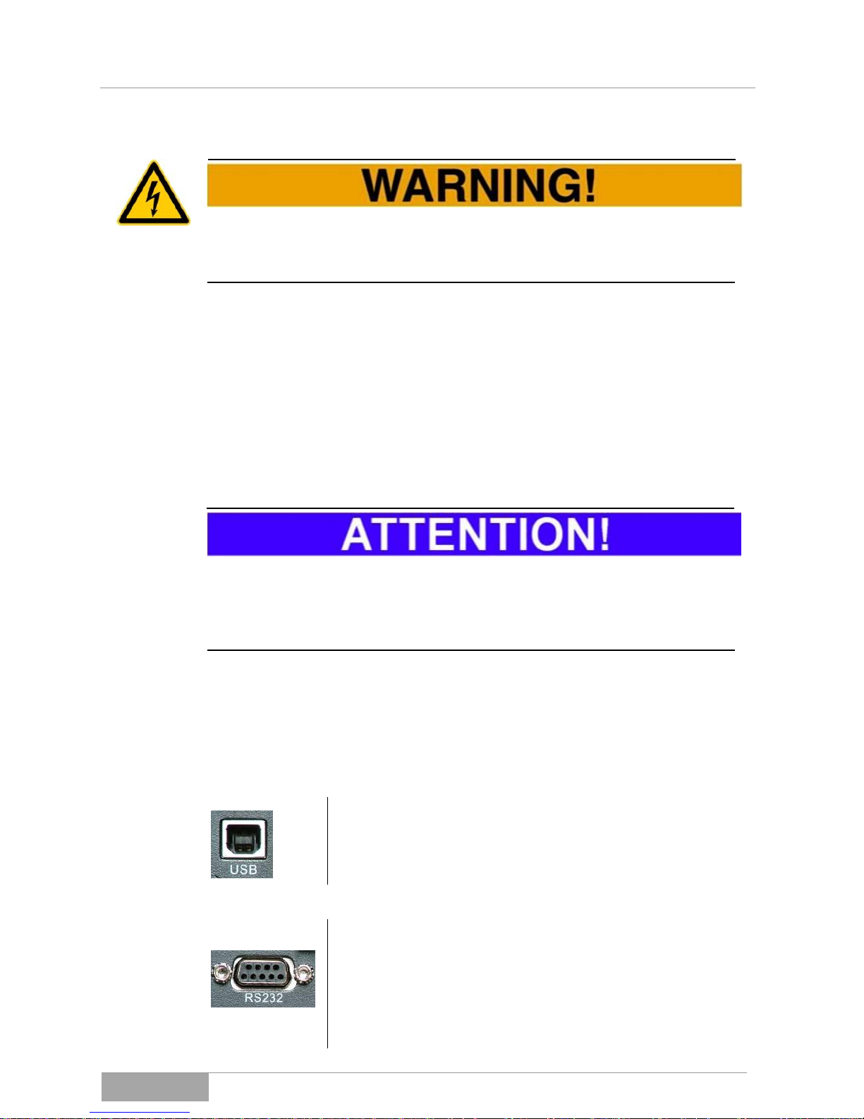
5.3.2 Connection of the USB and serial communication interfaces
There are two standard interfaces available to create direct communication with
the UPS. However, you cannot use both at the same time:
USB interface:
Connect the USB interface via a USB cable (type A to type
B) to your Computer or a suitable superordinate control
system. The interface works pursuant to USB protocol 1.1.
Serial RS232 interface:
Connect the serial interface via a serial cable (1:1) to your
Computer or a suitable superordinate control system. The
interface works pursuant to Megatec protocol. You will see
the configuration (on the side of the UPS) as follows:

MCI 700, 1000, 2000, 3000 VA (XL)
Installation and
Connection
MCI series
38
Pin Sub-D:
Description:
Function:
2
TxD
Send (output)
3
RxD
Receive (input)
5
PE
PE
5.3.3 EPO connector (EMERGENCY POWER OFF), dropping of loads
The EPO can be used as an external emergency/off function.
EPO, emergency/off contact:
Use the supplied double-pole plug for this and connect one
opener contact to it (e.g. emergency/off button). When the
button is activated, the UPS outlet is switched off (dropped).
If no emergency/off button or anything similar is being used,
the contact must be linked directly at the connector.
Lock the connector additionally with the lock screws to make sure it can never
become loose.
If the contact is open, the output is switched off.

MCI 700, 1000, 2000, 3000 VA (XL)
Operation
MCI series
39
6. Operation
Due to the extensive protective functions the device performs in relation to the
appliance/s, the UPS operates almost automatically.
The operational control of the device / equipment is thus limited to only a few
steps which is in addition to the limitation of authority. Consequently, the handling is divided into the "general operation" and the "maintenance and service
operation" of the UPS device.
In general, the operating personnel should inform any affected employees (keyword: consumer network) in advance about all planned tasks with regard to the
UPS.
Have the signals listed in chapter 8 Signalsready, so you are able to immediately interpret the operation display in the event of a fault.
6.1 Operation and operating behavior of the
UPS equipment
In general, the switching on or starting and the shutting down of the system is
performed by the operating personnel.
The operator of the UPS-equipment must always adhere to the instructions in
this operating manual. The operator may only carry out the following steps and
must always exercise particular care:
– Switching the UPS on / off;
– Reading of the display messages and interpretation of the acoustic
signals.
– Switching from normal operating mode to autonomous mode and
vice versa;
The operation of the UPS / equipment is premised on the condition that all previous chapters of this manual have already been successfully implemented and
inspected.

MCI 700, 1000, 2000, 3000 VA (XL)
Operation
MCI series
40
6.1.1 Switching the UPS on and starting of the equipment
Switching into STANDBY mode and starting the UPS equipment is performed
by way of the following procedure. Always follow the steps in the order described here:
• Check if EPO contact is closed.
• Turn on the circuit breaker of the mains power supply
or connect the UPS with the supply network via
power cord.
The UPS switches automatically
into STANDBY mode (mode 0).
The display message as shown
here is displayed. Furthermore
clearly to be seen, the charging
mode is already active. The loads
are not yet connected.
• Now press the ON button. Always keep the button
pressed until the selection is confirmed by an acoustic signal (beep).
The display changes to normal operating mode (mode 2). The charging mode continues to be active.
The UPS output is now connected,
or the loads are now fully supplied
and supported.
This concludes the procedure of turning on the equipment, the UPS or equipment can remain in this state, the loads may still have to be connected.
The starting process or switching into another operating mode may take a few
seconds, due to internal synchronizing processes being performed.

MCI 700, 1000, 2000, 3000 VA (XL)
Operation
MCI series
41
6.1.2 Turning-off the UPS
The following procedure lists the necessary steps switch off the UPS. Always
follow the steps in the order described here:
✓ The initial state of the equipment is normal operating
mode!
• First switch off all loads, one after the other, to en-
sure that they are shut down in a controlled manner;
• Stop the operation of the UPS by pressing the Off
button. The UPS returns into STANDBY mode, the
UPS output is switched off.
• Turn off the circuit breaker of the mains power supply
or disconnect the supply by unplugging the power
cord.
This completes the switching off process, the UPS equipment can remain in that
state.
6.1.3 Switching into autonomous mode
A disruption of the mains power supply forces the UPS into autonomous mode.
Follow the following instructions:
✓ The starting position for the equipment is normal op-
erating mode.
• Turn off the circuit breaker (mains power supply) or
unplug the power cord from the wall socket. The UPS
switches directly and thus without interruption of the
load supply, into autonomous mode;
The display changes to autonomous operating mode (mode 3).
The UPS output continues to be
connected, the loads are fully supplied and supported. The accumulator bank is now being discharged.
During the autonomous mode, the
buzzer will sound, emitting a beeping signal (interval: beep/45 seconds).
When the circuit breaker turns on again. or when the power cord is reconnected
with the mains power supply, the UPS switches back into normal operating
mode.

MCI 700, 1000, 2000, 3000 VA (XL)
Operation
MCI series
42
Often, a forced switch to autonomous mode is performed on purpose to text the
duration of the autonomous period (backup time) or the UPS equipment.
6.1.4 Direct switching to autonomous mode (COLD START)
Even if no connection to the mains power supply is established, the UPS can be
switched directly into autonomous mode. Follow the following instructions for
this process:
✓ Initial state, the equipment is completely turned off,
there is no connection to the mains power supply!
• Now press the ON button. Always keep the button
pressed until the selection is confirmed by an acoustic signal (beep).
The UPS turns on and remains in
STANDBY mode (mode 0). The
UPS only remains in this operating
state for a few seconds, as there is
no connection to the mains power
supply.
If the ON button is not reconfirmed
right away, the device will shut off
again by itself.
• Now please press the ON button a second time Al-
ways keep the button pressed until the selection is
confirmed by an acoustic signal (beep).
The display changes to autonomous operating mode (mode 3).
The UPS output is connected, the
loads are fully supplied and supported. The accumulator bank is
now being discharged.
During the autonomous mode, the
buzzer will sound, emitting a beeping signal (interval: beep/45 seconds).

MCI 700, 1000, 2000, 3000 VA (XL)
Operation
MCI series
43
A COLD START, also called BLACK START, is frequently used to perform
some load or static load tests with connected appliances in advance. While doing so, always monitor the load display (LOAD) on the control unit.
Do not leave the device / equipment in this state. Turn the device off again or
make sure, that the mains power supply is connected and that the device
switches into normal operating mode.
6.1.5 Turning the device mute during autonomous mode (MUTE MODE)
During the autonomous period, the acoustic signal, the buzzer (BUZZER) of the
UPS can be turned off.
✓ Initial state, the equipment is in autonomous mode,
the buzzer is active!
• Now press the ON button. Always keep the button
pressed until the selection is confirmed by an acoustic signal (beep).
The buzzer is now deactivated. No acoustic signal will sound until the UPS
changes into another operating mode. E.g. if the accumulator bank status "low"
(LOW) is reached due to the discharging of the accumulator bank, or if a warning or alarm signal is generated.
6.1.6 Test mode, inspection of the UPS
During the normal operating phase, the UPS can be run in test mode at any
time. This entails a brief test of the autonomous mode.
✓ The starting position for the equipment is normal op-
erating mode.
• Now press the ON button. Always keep the button
pressed until the selection is confirmed by an acoustic signal (beep).
The UPS immediately switches to autonomous mode, for about 10 s, and then
switches back to normal operating mode.

MCI 700, 1000, 2000, 3000 VA (XL)
Operation
MCI series
44
6.1.7 Warning signals of the UPS
If the UPS reaches a state of overload, e.g. due to load behavior, it emits a
warning signal in the form of a status display and an acoustic signal.
The UPS reports the issue by displaying a WARNING-CODE (here
29).
The signal is always also supported
acoustically.
See also the complete table of warnings for all operating modes of the UPS in
8 Signals, Error Codes and Troubleshooting Measures.
6.1.8 Fault mode of the UPS
If the UPS switches to fault mode due to an internal issue, it turns off the output.
The loads are no longer supplied, the display shows the information below (example):
The UPS reports the issue by displaying a FAULT-CODE (here 28).
The signal is always also supported
acoustically.
For safety reasons, the UPS cannot return from a fault mode into another oper
ating mode by itself. To achieve that, the device has to be manually switched off
and restarted. However, this step may only be taken, if the source of the fault
had first been identified and eliminated.
You find a complete list of all error codes summarized under
8 Signals, Error Codes and Troubleshooting Measures.
MCI 700, 1000, 2000, 3000 VA (XL)
Operation
MCI series
45
6.2 UPS settings
In general, all settings relevant to the UPS are set via the UPS control panel.
These include first and foremost:
Settings regarding the initial configuration of the UPS;
Turning the BYPASS mode on and off;
Selecting the UPS operating mode ( , , );
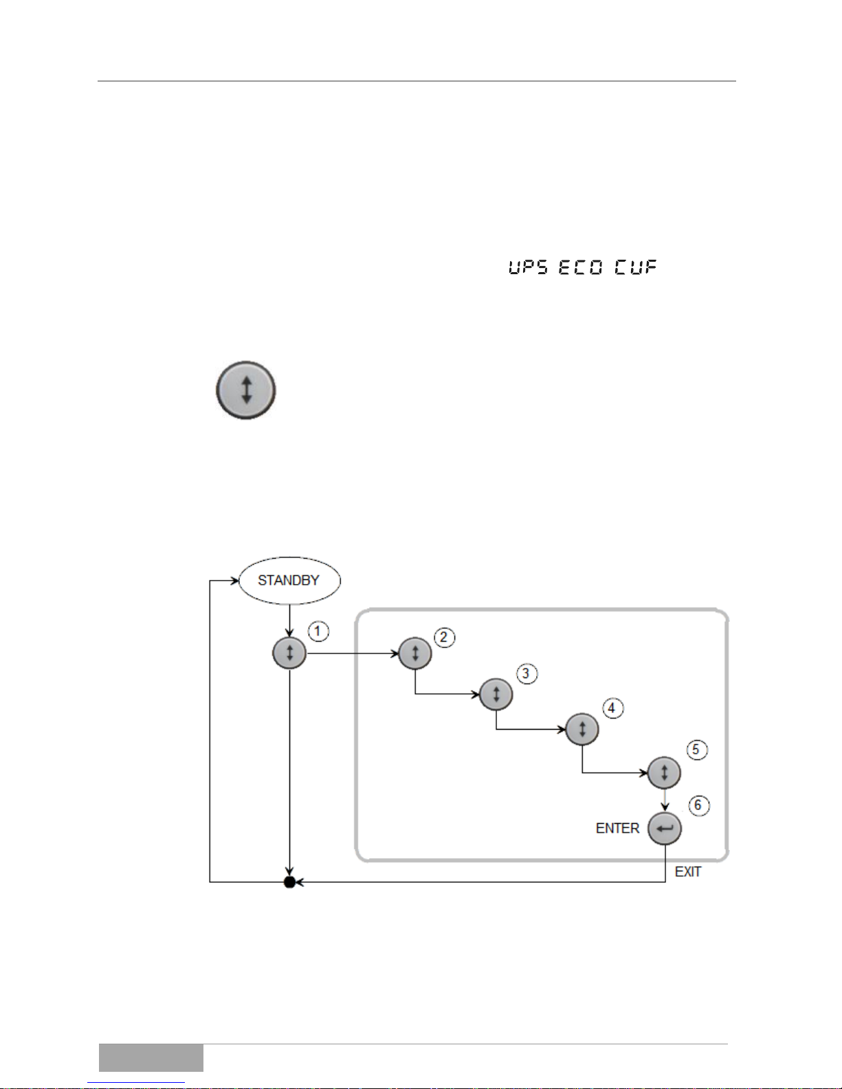
However, the UPS must be switched into STANDBY mode, before any settings
can be configured (Fig. 6-1):
• Now you can press the Selection key Always keep
the key pressed until the selection is confirmed by an
acoustic signal (beep).
The UPS immediately switches to the settings area and the current setting or
operating parameter are displayed as blinking. The parameter to be set is
selected by repeatedly pressing the selection key [(2), (3), (4), (5)], and then the
ENTER key (6) to confirm the desired selection. At the same time, by hitting the
Enter button, you automatically exit the settings area automatically.
Fig. 6-1 Diagram for the configuration of the parameters.
Additional parameter changes can be made by again pressing the selection key.
Once all parameters are set, the UPS can be switched back from STANDBY
mode into normal operating mode.
Settings Area

MCI 700, 1000, 2000, 3000 VA (XL)
Operation
MCI series
46
The following illustration additionally depicts the path of the CURSOR by hitting
the selection key through the individual parameters of the UPS.
Below, several settings are listed as examples:
Setting of output voltage of 230:
✓ The starting position for the equipment is STANDBY mode!
• Press the selection key to reach the selection mode;
• Press the Selection key again several times until you reach the pa-
rameter "230 VAC", that parameter should be blinking;
• Press the enter key, to confirm the selection. You will automatically
exit the settings area;
• Start the UPS again to operate it in support mode, here normal oper-
ating mode;
Setting the operating mode "ECO-MODE":
✓ The starting position for the equipment is STANDBY mode!
• Press the selection key to reach the selection mode;
• Press the Selection key again several times until you reach the pa-
rameter „ “ that parameter should be blinking;
• Press the enter key, to confirm the selection. You will automatically
exit the settings area;
• Start the UPS again to operate it in support mode (here: ECO-MODE,
LINE INTERACTIVE);

MCI 700, 1000, 2000, 3000 VA (XL)
Operation
MCI series
47
After starting the UPS it will only switch to ECO mode very slowly (approx. 20 s),
as several tests are run internally. Please have patience.
Setting the operating mode "BYPASS":
✓ The starting position for the equipment is STANDBY mode!
• Press the selection key to reach the selection mode;
• Press the selection key again several times until you reach the pa-
rameter "BYPASS ENABLE", that parameter should be blinking;
• Press the enter key, to confirm the selection. You automatically leave
the settings area and the UPS immediately switches into BYPASS
mode.
Do not leave the UPS in by-pass mode for any prolonged period of time. The
support function of the UPS is not active in this operating mode.
Deactivating the operating mode "BYPASS":
✓ The starting position for the equipment is "BYPASS" mode!
• Press the selection key to reach the selection mode;
• Press the selection key again several times until you reach the pa-
rameter "BYPASS DISABLE", that parameter should be blinking;
• Press the enter key, to confirm the selection. You automatically leave
the settings area and the UPS immediately switches into STANDBY
mode.
• Switch, or turn on the UPS, for the equipment to work in normal oper-
ating mode again, and consequently to provide the full support
backup function;

UPS: MPR 2000 (RACKMOUNT)
Commissioning
MCI series
48
7. Commissioning of the UPS
The commissioning is premised on the condition that all previous chapters of
this manual have already been successfully implemented and inspected.
In addition, check whether all connected loads are and turned off. The commissioning of the UPS equipment may only be performed by accredited service personnel.
Please proceed with the commissioning tasks in the following sequence:
✓ Initial situation: If an external accumulator bank is being use, it is al-
ready connected to the device.
• Switch the circuit breaker or the mains power supply on;
The UPS switches into STANDBY mode and begins charging.
It is possible to operate the device in charging mode for several hours, to
achieve a fully charged accumulator bank, prior to commissioning the UPS to
assume its full support function.
• Now start the equipment by pressing the ON button. The UPS
switches to normal operating mode (mains operation) and the UPS
output is now active;
• Check all the status information and parameters on the display;
• Now turn on the individual loads one after the other, while checking
the displayed power output values;
• Briefly test the autonomous mode operation, while again checking the
power output values and status information;
• You can leave the UPS in normal operating mode (mains operation),
the loads are now fully protected by the UPS.
• Turning the UPS off requires the same process in reversed order.
In the event that any errors occur during the commissioning procedure, these
errors must first be analyzed and eliminated before you continue with the commissioning.

MCI 700, 1000, 2000, 3000 VA (XL)
Error messages
MCI series
49
8. Signals, Error Codes and Troubleshooting Measures
Status messages of the UPS
The following list shows the status messages of the individual operating modes
of the UPS in a table:
Operating mode:
Reporting number
(MODE):
Additional
symbols:
STANDBY mode
0
BYPASS mode
1
x
Normal operating mode
2
Autonomous mode
3
x
Test mode
4
x
ECO mode
5
Converter mode
6
Warning signals of the UPS
The following list shows the warning messages of the individual operating
modes of the UPS in a table:
Operating state:
Report number
(WARNING):
Additional
symbols:
Polarity, mains power supply
(L and N)
09
x
Vent fault
10
x
Accumulator bank voltage too
high
11
x
Accumulator bank voltage low
12
x
Charging error
13
x
DC converter temperature high
21
x
INVERTER temperature high
24
x
ambient temperature high
25
x
Mains voltage high
26
x
Accumulator bank not connected
27
x
Overload at output
29
x
EPO triggered!
30
EPO
x

MCI 700, 1000, 2000, 3000 VA (XL)
Error messages
MCI series
50
Error messages of the UPS
The following list shows the error messages of the individual operating modes of
the UPS in a table:
Error status:
Report number
(FAULT):
Additional
symbols:
Internal Bus fault
05
x
INVERTER error
06
x
Overload at output
07
x
Over temperature error
08
x
INVERTER short circuit
14
x
Internal Bus short circuit
28
x
Cause of error and troubleshooting
If the UPS equipment does not operate correctly, please first check the status,
warning, and error messages on the LC-display.
You can furthermore attempt to narrow down the problem using the following
table:
Problem:
Possible cause
Troubleshooting measures:
No display, UPS
does not turn on:
The connection to the
mains power supply is not
fully functional or not
plugged in right.
Check the power line / cable or the
mains power supply.
The display
shows MODE 00
despite existing
mains power
supply:
The UPS is not turned on.
Press the ON button.
The display
shows MODE 03
despite existing
mains power
connection:
The mains supply is down
(voltage, frequency) or
outside the thresholds.
Check the mains power supply.
The autonomous
time span is
shorter than indicated.
Either the accumulator
bank has not been fully
charged, or the accumulators are faulty or their capacity degenerate.
Charge the accumulator bank for at
least 10 hours and then meter the autonomy time span again. If this
should not be successful or if the remaining autonomy time span is insufficient for your needs, the accumulators have to be changed.
Vent fault
WARNING 10:
Vent is faulty or blocked.
Check whether the vent can rotate
freely.

MCI 700, 1000, 2000, 3000 VA (XL)
Error messages
MCI series
51
The accumulator
bank voltage too
high
The end of charging voltage of the accumulator
bank is too high.
In this case, the UPS automatically
switches to autonomous mode to discharge the accumulator bank and
later switches back to normal operating mode.
The accumulator
bank voltage is
low during autonomous mode:
The accumulator bank
voltage is almost fully discharged.
The equipment will automatically shut
down after the end voltage is
reached.
Charging error:
Charging is not possible.
The UPS has to be returned to the
manufacturer for inspection.
The DC converter is too
high:
Parts of the UPS have
overheated.
Check the ventilation of the UPS or
the ambient temperature.
The INVERTER
temperature is
too high
Parts of the UPS have
overheated.
Check the ventilation of the UPS or
the ambient temperature.
The mains voltage is too high:
The connected mains
voltage is too high.
In this case the device switches to
autonomous mode and then automatically switches back, once the mains
voltage is within the limits again.
The accumulator
bank is not connected
The accumulator voltage
is interrupted or not exiting:
Check the accumulator bank circuit. It
must be closed and connected to
voltage.
Overload at output:
The load response of the
loads is too high.
Check the loads or turn one load after the other off while monitoring the
load values on the display.
EPO display,
emergency/Off is
active:
The EPO function is activated or the contact is
open.
Close the EPO contact. Then turn off
the device completely. After that you
can restart the UPS again.
Internal Bus
fault:
Crucial internal error.
Send the device back for inspection.
INVERTER error:
Crucial internal error.
Send the device back for inspection.
Over temperature fault:
Crucial internal error.
Send the device back for inspection.
Internal Bus
short circuit:
Crucial internal error.
Send the device back for inspection.
Never try to start the UPS when there is any error. Always eliminate the cause
of error first and then restart the device.

MCI 700, 1000, 2000, 3000 VA (XL)
Error messages
MCI series
52
9. Troubleshooting
Over the course of time malfunctioning or failures of the UPS, the accumulator
bank or their periphery may occur. Should this be the case, please contact our
customer service (service hot-line) as soon as possible.
When you contact the service center, please provide the following information to
ensure swift resolution:
– Model number, serial number and configuration of the equipment;
– Date on which the issue first occurred and process;
– Control panel LCD/LED display information (status or warning or
alarm messages);
– Condition of the mains power supply, load condition, environment
conditions, temperature and moisture, ventilation conditions;
– Information on the condition, like the age of the accumulator bank;
Please always name the responsible competent contact person for the clarification of the issue and its resolution.
10. Service hot-line
Should you in general encounter any problems or need any information regarding safety, please contact our service hot-line:
Phone: 0049 / (0) 741 – 17451-52
Fax: 0049 / (0) 741 – 17451-29
You can also reach us via e-mail at:
kundendienst@effekta.com
In addition you can contact the central area or branch office directly as listed on
our website:
http://www.effekta.com

UPS: MPR 2000 (RACKMOUNT)
Software
MCI series
53
11. Software
The UPS management software runs as a client / server application for heterogeneous networks or on a local computer.
It works on any common platform (Win, Linux, UNIX).
Remote access to the UPS and its data is possible and can be logged.
The software shows all relevant UPS data like accumulator condition, tempera-
ture, condition of the mains power supply, among others in a clear and simple
graphic interface.
Malfunctioning of the system can be reported easily via e-mail, mobile phone or
fax.
The range of services can be roughly summarized as follows:
– available for Windows 95/98/2000/NT/XP/Vista/Win7, Novell, Linux,
etc.;
– local or network SHUTDOWN;
– integrated SNMP-sub-agent;
– graphic user interface with all UPS data;
– event-based sending of network news;
– event-based sending of e-mails and texts;
– recording (LOGGING) of all UPS status data and measurements;
– scheduler (SCHEDULER) for time controlled execution of functions
like REBOOT, SHUTDOWN, etc.;
The software package is included in the scope of delivery of the equipment.
Please see the respective manual on the CD for additional in-formation on the
performance, installation, use etc.

MCI 700, 1000, 2000, 3000 VA (XL)
Maintenance and
Service
MCI series
54
12. Maintenance and Service
You may expect a long service life and interference-free operation of your UPS.
However, the service life and reliability of the UPS is greatly dependent on the
ambient conditions. The ambient temperature and humidity must remain within
the specified thresholds. In addition, the area around the UPS should be kept
clean and free of dust.
At an ideal ambient temperature range of about 20-25°C, the service life of the
accumulators is typically around 4 years. Through the use of special accumulators the service life can be significantly increased (up to 8 years).
You should periodically (every 6 - 12 months) check, whether the remaining autonomy time (backup time) is sufficient for the intended purposes. Once that is
no longer the case, the accumulators of the accumulator bank(s) have to be replaced.
12.1 Measuring back-up time (autonomy period)
Before you begin this procedure, please make sure to save all open data. Furthermore, inform all affected employees about your intended task.
Basically there are two different methods for measuring the back-up time.
Method a) measures the actual back-up time, which means that at the end of
that autonomy period the appliances would be without a power supply.
Method b)
allows to determine the residual capacity after a defined backup-period. In this
case the appliances will usually not be without power in the end. To use either
method, you have to force the UPS into backup mode, by disconnecting the
power supply of the UPS (pull the power plug). After the measurement has been
carried out, turn the power supply back on (plug the power plug back in ) and/or
turn on the UPS as usual.
Remember that after the measuring of the autonomy time, the accumulators of
the system may possibly be discharged. I.e. the UPS must operate in normal
operating mode for several hours (min. 6 hours) to charge the accumulator
bank, before it is operational (able to provide backup support) again at about
80%.

MCI 700, 1000, 2000, 3000 VA (XL)
Maintenance and
Service
MCI series
55
If the backup time is not measured due to local conditions or instructions, we
recommend a prophylactic replacement of the accumulators
every two years, to avoid any risk of insufficient autonomy time (backup time)
because of degenerated accumulators.
In addition, the fans and ventilation ducts of the equipment should be inspected
regularly and cleaned if needed. This ensures, among other things, full output
power. The frequency of the inspection and cleaning depends very much on the
environment of the equipment (key word: dust).
12.2 Replacing components / accumulators
Only EFFEKTA Regeltechnik service personnel or personnel of other accredited
service points is authorized to replace accumulators in the UPS or in an external
accumulator bank, as well as other UPS components.
During the replacement of accumulators and other components, the loads are
directly connected to the mains power supply via a manual by-pass, which
means there is no protection or back-up function by the UPS during this period.
Mains power failures or other grid problems are directly transferred to the load.

MCI 700, 1000, 2000, 3000 VA (XL)
Maintenance and
Service
MCI series
56
12.3 Maintenance and service contracts
EFFEKTA Regeltechnik GmbH also offers the related maintenance services to
ensure the highest possible reliability and availability of the UPS. In addition, we
offer maintenance contracts to support and assist you in the following areas with
our qualified staff:
Regular testing of the UPS, in particular the accumulators,
as well as timely replacement of accumulators.
Inspection of the UPS installation and functionality.
Measuring the remaining autonomous period.
Professional cleaning, which is of particular importance for
the ventilation components.
Proper disposal of defective or degenerated components.
Environmentally acceptable disposal of accumulators.
Please contact our Service hot-line listed above for a complete list of our services or send us an e-mail request.

MCI 700, 1000, 2000, 3000 VA (XL)
Maintenance and
Service
MCI series
57
12.4 Service-Log
Please always enter all maintenance and service work conducted on the UPS
equipment into the service-log.
Date
Performed tasks
Performed by

MCI 700, 1000, 2000, 3000 VA (XL)
Technical Data
MCI series
58
13. Technical Data
MCI:
700 (XL)
1000 (XL)
2000 (XL)
3000 (XL)
UPS input:
Connection
1 phase, neutral and protective earth
Voltage range
110 - 300 VAC
BYPASS range
110 - 276 VAC
Frequency range
45~55 Hz, 54~66 Hz (50/60 Hz automatic detection)
Input current
3,5 (5,0) A
4,8 (6,4) A
9,8 (14,0) A
14,4 (18,5) A
UPS output
Power output values * **
***
700 VA
630 W
1000 VA
900 W
2000 VA
1800 W
3000 VA
2700 W
Connection
1 phase, neutral and protective earth
Nominal voltage
208 / 220 / 230 / 240 VAC
Voltage accuracy
2 % (INVERTER mode)
Frequency
50/60 Hz 0,2 % (INVERTER mode)
Wave form
pure sinus
POWER FACTOR
0,9
Overload
105~110 %: 60 s, 110~125 %: 30 s, 125~150 %: 10 s, >150 %: 1
s
THD
< 3 % with linear load, < 5 % with non-linear load
Switching time
Mains <> INVERTER: 0 ms
Switching time (ECO)
BYPASS <> INVERTER: max. 4 ms
Charging unit
nom. charging voltage
36 VDC
36 VDC
96 VDC
96 VDC
Charging current
1 A (8 A)
1 A (8 A)
1 A (4,8,12 A)
1 A (4,8,12 A)
Charging time / capacity
< 6 h / 90 % of capacity (XL: depending on assembly)
Internal accumulator bank
Number of accumulators
3 3 8
8
Type of accumulator
AGM (12 V)
7 Ah (9 Ah)
7 Ah (9 Ah)
7 Ah (9 Ah)
7 Ah (9 Ah)
Device
Efficiency factor
> 94 % ECO, > 88 % normal operating mode, > 85 % autonomy
mode

MCI 700, 1000, 2000, 3000 VA (XL)
Technical Data
MCI series
59
Device protection
Overload, total discharge, over-charging
Measurements W x D x
H [mm]
145x400x220
145x400x220
192x460x347
192x460x347
Weight [kg]
13
13
31
31
UPS category
VFI-SS-111
Device protection class
IP20
Integrated communication
RS232, USB (not simultaneously usable)
Communication (option)
Intelligent interface cards: SNMP, contact interface
Standards / Guidelines
Safety: EN 62040-1
EMV: EN 62040-2
Operation: EN 62040-3
CE
EMV class
C1
Temperature ranges
Operation: 0 ~ 40 °C
recommended: + 15 ~ + 25 °C
(Outside the recommended range, the battery life is considerably
reduced)
Storage: -25 ~ 55 °C (without accumulator bank!)
rel. humidity
0 ~ 95 % (not condensing)
Noise level
approx. 50 dB
Cooling
Vent cooling, force convection;
* the power output is reduced to 90 % at an output voltage of 208 VAC,
** the power output is reduced to 80 % at an output voltage of 200 VAC,
*** power output up to 1000 m (MSL) 100% (* 90%, ** 80%), >1000 m reduces the power output by 1% /
100 m.
13.1 Typical autonomy periods
MCI:
700
1000
2000
3000
UPS autonomy periods
Load 50 %
approx. 20
min.
approx. 10
min.
approx. 18
min.
approx. 10
min.
Load 100 %
> 10 min.
> 4 min.
> 8 min.
> 4 min.
XL model
depending on assembly
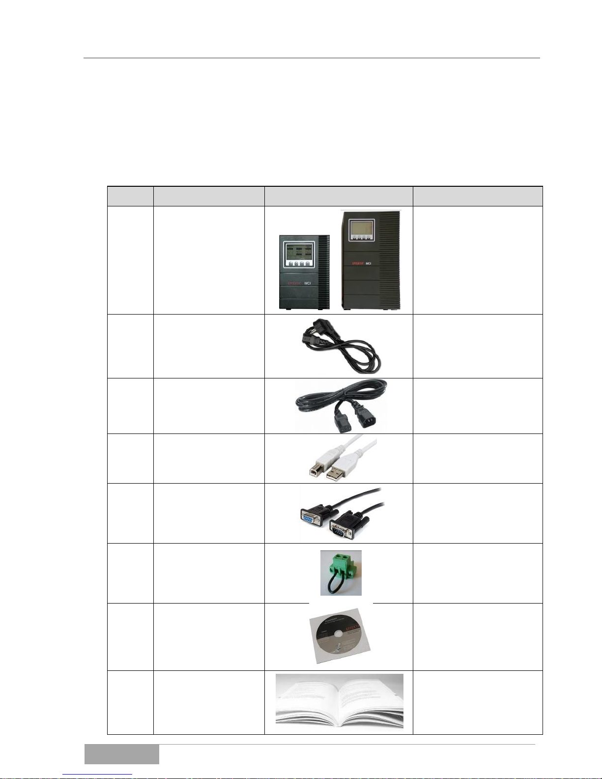
MCI 700, 1000, 2000, 3000 VA (XL)
Accessories
MCI series
60
14. Scope of delivery/ Accessories
Below you find the list of the scope of delivery, please check your delivery for
completeness. Please let us know immediately, should any items or components be missing in your delivery.
Number
Article or Article No.
Function / View:
Description:
1 x
UPS
MCI series,
(according to your order)
1 x
power cord:
CEE power cable pursuant to IEC 60320
Connector types:
C13 (700, 1000),
C19 (2000, 3000);
1x
Output cable:
CEE power cable pursuant to IEC 60320
Connector types:
C13 / C14;
1x
USB
Connector types:
type A, to type B
1x
serial
RS232 cable (1:1)
1x
EPO
EPO plug with bridge,
screwable;
1x
Software
PowerShut Plus for all
common operating systems
1 x
Operating Manual
Operating Manual - English V 2.1;
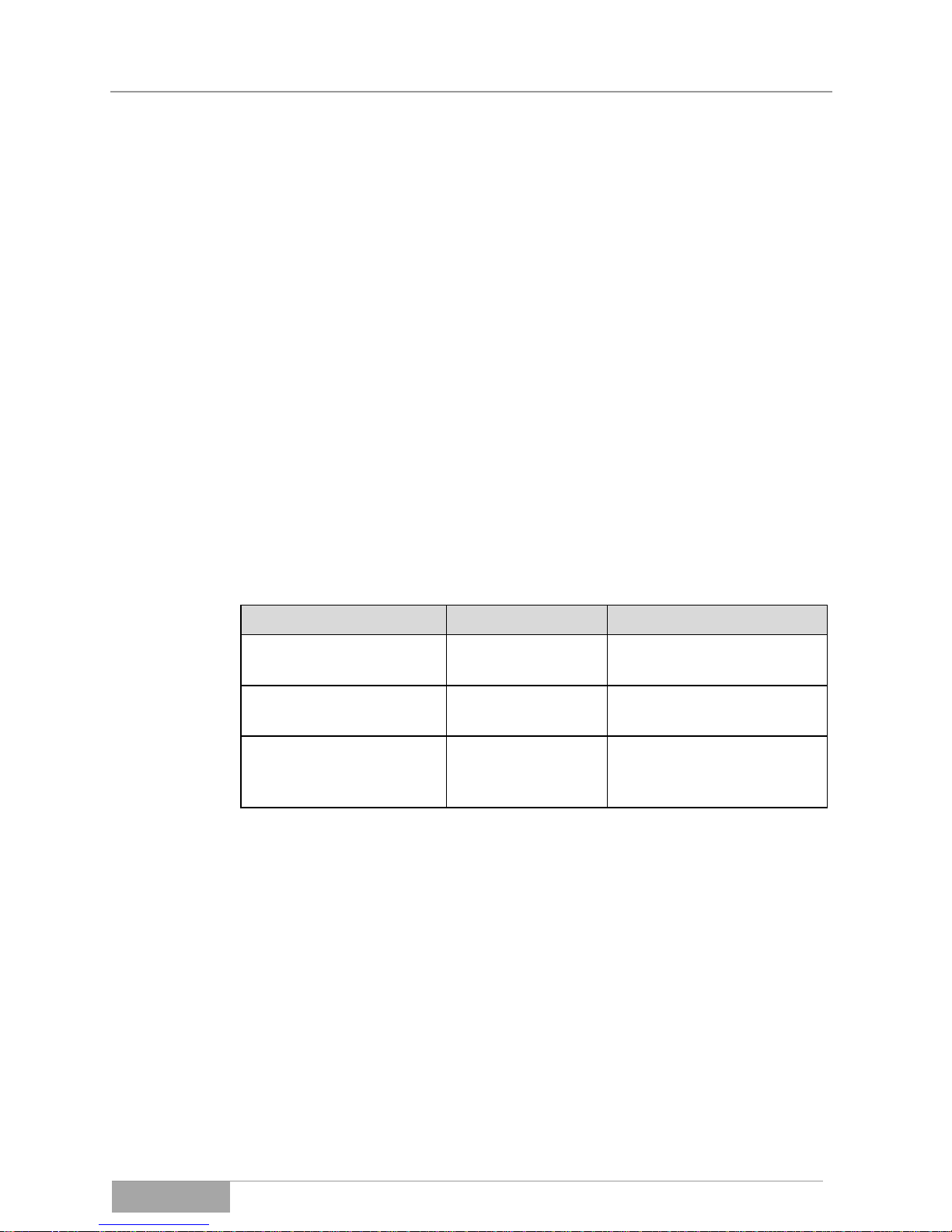
MCI 700, 1000, 2000, 3000 VA (XL)
Accessories
MCI series
61
15. Optional accessories
The components, devices and/or equipment listed below are accessories that fit
the MCI series and that have been tested and approved by EFFEKTA Regeltechnik GmbH.
15.1 External accumulator bank and connection cable
Every UPS system requires an energy storage to supply the stored power to the
loads during a power failure. The external accumulator banks can either be
used as the sole energy storage or in addition to an internal accumulator bank,
to extend the autonomous period and/or adjust the necessary load balance.
Due to the different requirements of customers, the accumulator banks are built
and assembled individually with regard to their size. In addition, several standard sizes are offered. The MCI series is already equipped for the adaptation of
an external accumulator bank. In addition, the following tested accumulator
bank components are available for the MCI series, which can be configured in
their capacity and voltage through the assembly of accumulators:
Article or Article No.
Function / View:
Description:
ABC8XXXXXXXXX300
Energy storage.
Accumulator bank (standalone unit, casing size M).
ABC9XXXXXXXXX300
Energy storage.
Accumulator bank (standalone unit, casing size L).
DC connection
Connection cord (80 cm)
accumulator bank <->
UPS.
Please contact our sales and service point to develop a suitable accumulator
bank concept for your needs.
15.2 External BYPASS
An external by-pass system allows the operation of the loads in two different
paths. In UPS operating mode (Fig. 15-1) the UPS system is integrated into the
current path and the loads are protected in the usual manner. In BYPASS mode
(Fig. 15-2) the load is directly connected to the mains power supply and the
UPS input and output are isolated.

MCI 700, 1000, 2000, 3000 VA (XL)
Accessories
MCI series
62
Fig. 15-1 UPS mode
Fig. 15-2 BYPASS mode
In this case, maintenance and service tasks of the UPS or the accumulator bank
can be performed in a fast and safe manner.
On rare occasions, the UPS or its components can also be replaced without interruption of the loads. In addition, using an external by-pass results in a more
cost efficient and transparent installation of the UPS system.
The following tested BYPASS components are available for the MCI series:
Article or Article No.
Function / View:
Description:
ZBBEFBEINBYP1012
ext. BYPASS
1-phase
Ext. manual BYPASS, 10 A
for MCI 700, MCI1000
ZBBEFBEINBYP1610
ext. BYPASS
1-phase
Ext. manual BYPASS, 10/16 A
for MCI 2000
ZBBEFBEINBYP1612
ext. BYPASS
1-phase
Ext. manual BYPASS, 16 A
for MCI 3000
ZBBEFBEINBYP16XL
ext. BYPASS
1-phase
Ext. manual BYPASS, 20 A
for MCI 3000XL
15.3 Communication adapter SNMP
The SNMP adapter integrates the UPS into a network and communicates via
TCP/IP, Telnet or FTP. After assigning an individual IP-address, the UPS can
be accessed from any location, which is of particular interest for remote administration and maintenance of the equipment.
Fig. 15-3 SNMP adapter to connect the UPS to a network.
The SNMP adapter can easily be slid into the adapter slow (INTELLIGENT
SLOT) of the UPS and only has to be connected with an Ethernet cable.

MCI 700, 1000, 2000, 3000 VA (XL)
Accessories
MCI series
63
For additional information about this product and the associated software please
contact our sales and service centers.
15.4 Communication adapter, relay card (Z0C/AS400)
The relay card is also an intelligent extension card and is used for the direct and
floating coupling with external controls and/or machines. This allows for the UPS
status to be transmitted to higher-level controls in real time.
Fig. 15-4 Relay card AS400 or real-time monitoring of the UPS.
The following signals are available for the monitoring and control:
Function:
Connection
type:
Mains failure
Output
Accumulator bank voltage low
Output
BYPASS mode
Output
UPS fault
Output
SHUT DOWN process
Output
UPS collective alarm
Output
Test mode
Output
Overload
Output
Remote trigger:
Shut down (SHUT DOWN)
Input
EPO
Input
Remote trigger UPS on/off
Input
All inputs and outputs have protective insulation or are floating. The relay card
can easily be slid into the adapter slot (INTELLIGENT SLOT) of the UPS and
has to be connected with an upstream control unit via a signaling cable. Furthermore, the card can be configured in a way that overall, the allocation and the
switching characteristics can be defined.
For details regarding the card and the connection, please see the operating
manual of the relay card.

MCI 700, 1000, 2000, 3000 VA (XL)
Conformity
MCI series
64
For additional information about this product please contact our sales and service centers.
16. Wearing parts list
The following list of components are related to regular wear and are therefore
not subject to the warranty of the UPS:
Wearing part
Function
Article number
XXXX XX XX **
Accumulator (BATTERY)
12 V xx Ah
Energy storage
Depending on assembly!
** Please check your accumulator delivery documents for the name and identification of the accumulators, or contact the service hot-line.
17. Conformity Declarations
All units labeled with a CE sign fulfill the EU harmonized standards and regulations.
The EU-declaration of conformity for this product is available upon request.
Please contact our 10 Service hot-line.
You can also find the declaration of conformity for this product on our website:
http://www.effekta.com

MCI 700, 1000, 2000, 3000 VA (XL)
Notes
MCI series
65

MCI 700, 1000, 2000, 3000 VA (XL)
Notes
MCI series
66

MCI 700, 1000, 2000, 3000 VA (XL)
Notes
MCI series
67

MCI 700, 1000, 2000, 3000 VA (XL)
Notes
MCI series
68
EFFEKTA Regeltechnik GmbH
Rheinwaldstraße 34
D – 78628 Rottweil/Germany
 Loading...