

Page 1
Installation Instructions for Cat. 105 Series
Adverse Location Visual Signals
Description
The 105 Series visual signals are heavy duty, reliable, UL,
cUL (General Utility) and CSFM listed (misc. device/control
unit accessory) beacons which, when assembled in accordance with installation instructions, constitute a UL listed
T ype 4X enclosure and are UL Listed for Marine Use. They
are designed for use in industrial applications or in appli-
T able 1. Hazardous Location Ratings
Cat. No. Class Division Group Operating Temperature
105FINH*-G1 I 2 A, B, C, D T2D (215C, 419F)
105SINH*-G1 I I 2 F, G T4A (120C, 248F)
105FINH*-G5 I I I T4A (120C, 248F)
105SINH*-G5
105FINH*-N5 I 2 A, B, C, D T2 (300C, 572F)
105SINH*-N5 I I 2 F, G T4 (135C, 275F)
I I I T4 (135C, 275F)
105HIST*-N5 I 2 A, B, C, D T2 (300C, 572F)
105HIST*-R5 I I 2 F, G T3B (165C, 329F)
I I I T3B (165C, 329F)
105HIST*-EK I 2 A, B, C, D T2A (280C, 536F)
I I 2 F, G T3B (165C, 329F)
I I I T3B (165C, 329F)
105ST*-G1 I 2 A, B, C, D T3 (200C, 392F)
105ST*-N5 I I 2 F, G T4A (120C, 248F)
105ST*-R5 I I I T4A (120C, 248F)
105FLED*-N5 I 2 A, B, C, D T5 (100C, 212F)
105SLED*-N5 I I 2 F, G T5 (100C, 212F)
105FLED*-G1 I I I T5 (100C, 212F)
105SLED*-G1
cations where a T ype 4X enclosure is required. The units
are available in steady-on halogen or LED, flashing halogen or LED, 3 Joule strobe or 8 Joule high intensity strobe.
When assembled in accordance with these instructions,
the 105 Series visual signals are UL Listed for use in Hazardous Locations with Operating Temperatures listed in
T able 1.
For specification details, see T able 2.
Installation
WARNING
To prevent electrical shock, do not connect power
until instructed to do so.
Installation must be in accordance with local codes. The
lens should be positioned up for outdoor applications.
1. Select a mounting configuration (Figure 6).
NOTE: When mounting using the Cat. No. 105BM
mounting bracket, the Cat. No. 105BX outlet
box attachment must also be used as shown in
Figure 1.
2. Pull field wiring into the mounting attachment.
WARNING
The 105BX junction box, 105BM mounting bracket
and 105PM pipe mount attachments are non-conductive plastic fixtures and do not provide earth-ground
continuity when attached to metallic wiring systems.
Therefore, they are intended for use with the 105
series visual signals only when earth-grounding is
not required.
WARNING
The 105BX junction box, 105BM mounting bracket
and 105PM pipe mount attachments can be used with
metallic wiring systems only when installed at the
end of a run.
3. Install the mounting attachment as follows:
a. Cat. No. 105BX: Screw the outlet box attachment
to the mounting surface using two screws (not
supplied). suitable for the surface. Attach the
adhesive backed gasket to the top of the 105BX
mounting box, being careful to line up the holes
in the gasket with the mounting holes in the outlet
box.
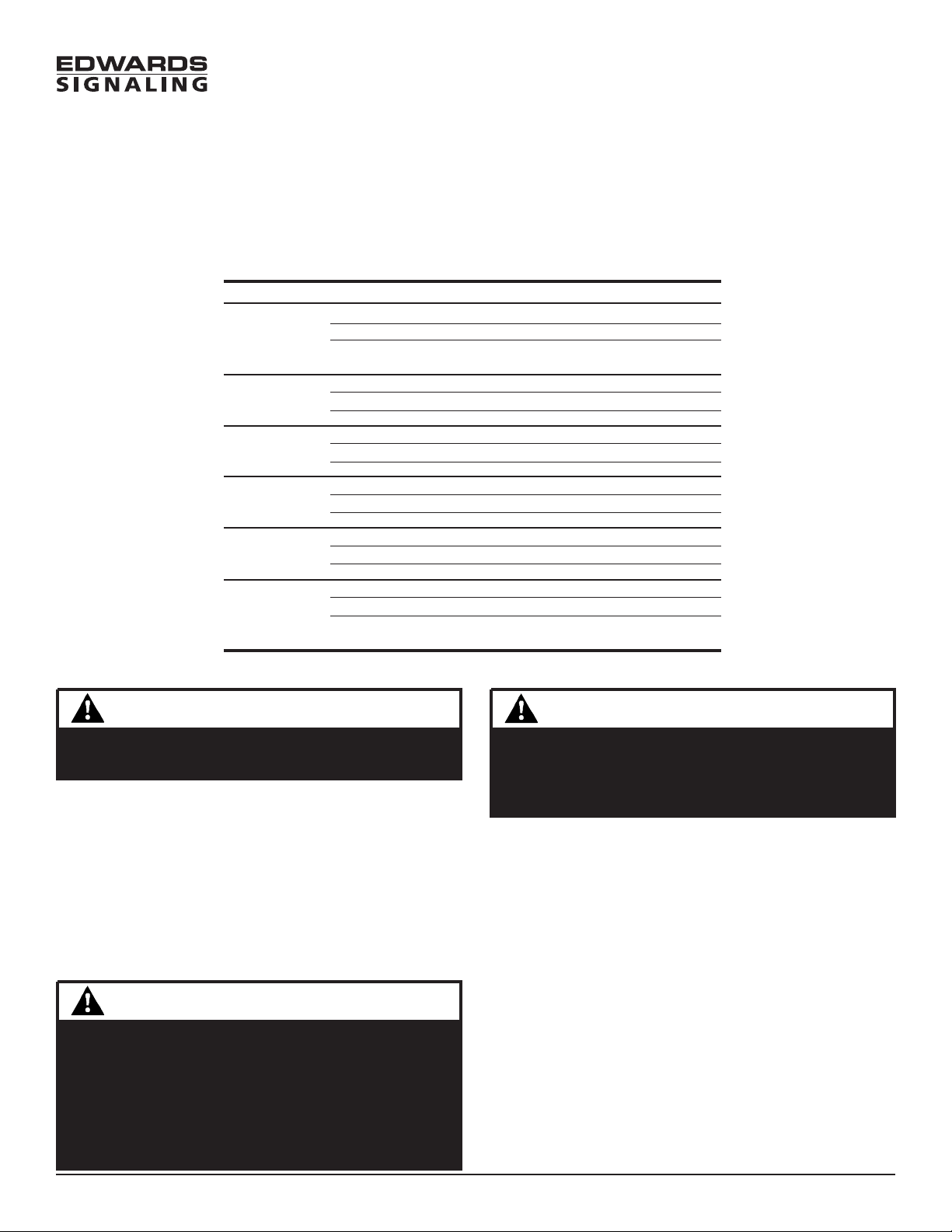
b. Cat. No. 105BM: Using the four supplied screws,
secure the mounting bracket to Cat. No. 105BX
outlet box attachment as shown in Figure 1. Attach
the adhesive backed gasket to the top of the 105BM
mounting bracket, being careful to line up the
holes in the gasket with the mounting holes in
the outlet box.
c. Cat. No. 105PM: Install 3/4" (19 mm) conduit.
Screw the pipe mount attachment onto the 3/4"
(19 mm) conduit. Attach the adhesive backed
gasket to the top of the 105PM pipe mount
attachment, being careful to line up the holes in
P/N 3100290 ISSUE 3 © 2002
Page 2
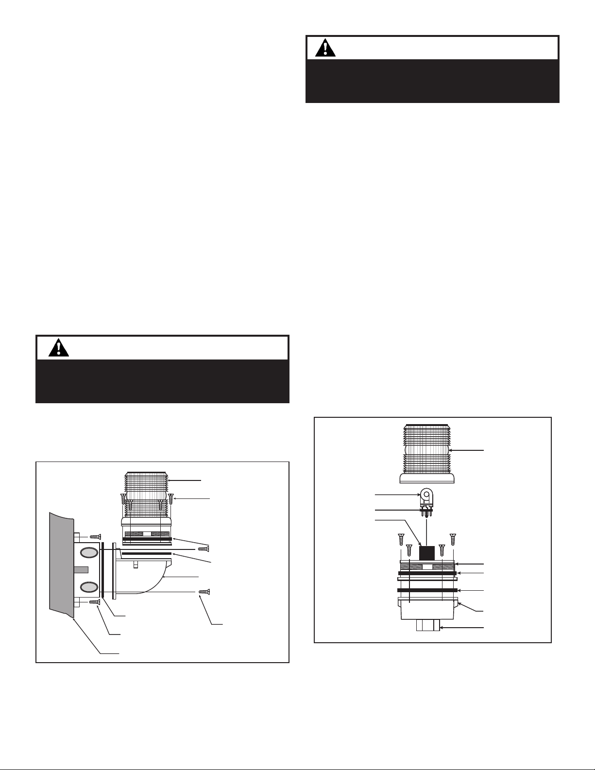
Strobe tube
Strobe tube base
Strobe tube
socket
105-L Series
Lens
Beacon Base
Gasket
Adhesive backed
gasket
105PM Pipe Mount
Attachment
3/4" (19 mm) conduit
nipple
the gasket with the mounting holes in the outlet
box.
NOTE: It is not necessary to remove the lens from the
Hi-Intensity Strobe Base to install the 105HIST
series beacons.
4. Mount 105SLED, 105FLED, 105SINH, 105FINH, and 105ST
Series as follows. Unscrew the gasketed base from the
lens assembly as shown in Figure 2 and remove the
clear gasket from around the base.
5. Secure the base to the appropriate mounting
attachment using four screws (supplied). Replace the
clear gasket on the base with the flared, open end
facing down.
6. Attach the unit's wire leads to the field wiring as shown
in Figure 4.
7. Ensuring that the light source is in place, screw the
lens back on the base.
8. Mount the 105HIST Series as follows. Secure the
hi-intensity strobe base to the appropriate mounting
attachment using four screws (supplied) as shown in
Figure 3.
9. Apply power and verify operability .
CAUTION
Do not touc h the strobe tube or halogen bulb with
bare fingers. Grasp the light source either by the
base or using a soft, clean cloth.
Light Source Replacement
1. Unscrew the lens from the base.
2. For Halogen Bulb Replacement:
a. While pressing down on the bulb, turn and then
pull straight up and out of the socket.
b. Insert the new halogen bulb into the socket, press
down and turn until the bulb is locked into place.
3. For Strobe T ube Replacement:
a. Grasp the strobe tube by its base and pull straight
up out of the strobe tube socket (Figure 2).
b. Grasp the new strobe tube by the strobe tube base
and press into the strobe tube socket.
4. Screw the lens onto the base.
5. Apply power and verify operability .
Maintenance
WARNING
To prevent electrical shock, before starting work on
units disconnect po wer and, for strobe modules
wait 5 minutes f or stored energy to dissipate.
The lens should be periodically cleaned using a mild detergent and water on a soft, clean, lint-free cloth.
105-L Series
Lens
(4) Countersunk screws
to mount lens to 105BM
(supplied)
Gasket
Adhesive backed
gasket
105BM Mounting
Bracket
P/N 3100290 ISSUE 3
Adhesive backed
gasket
(2) Screws to mount
105BX to the
mounting surface
Mounting
Surface
(4) Screws to mount
105BM to 105BX
(supplied)
Figure 1. Mounting Cat. No. 105BM Mounting
Bracket
Figure 2. Securing the Beacon to the Mounting
Attachment
(Pipe Mount Attachment shown)
Page 3
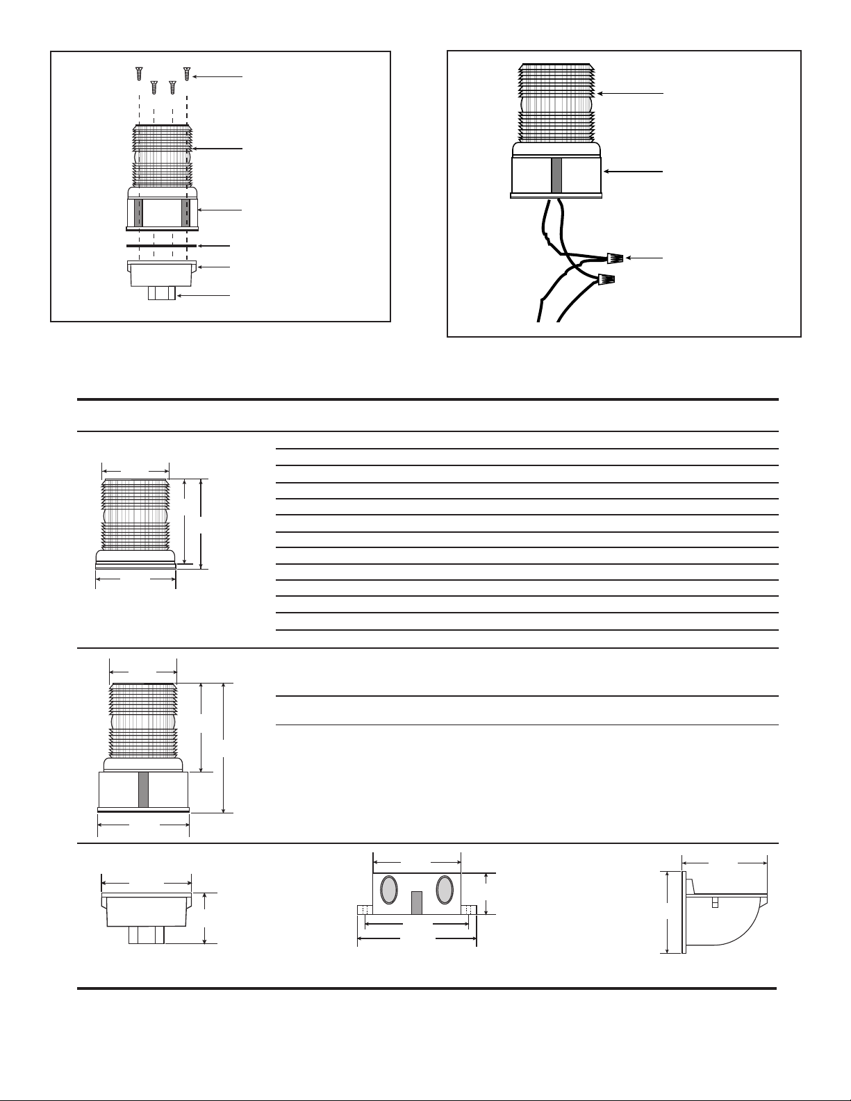
(4) Screws to mount
3.625"
(92 mm)
4.375"
(111 mm)
4.625"
(117 mm)
4.5"
(114 mm)
lens to 105PM
(supplied)
105HI-L Series
Lens
Hi-Intensity Strobe Base
Adhesive backed
gasket
105PM Pipe Mount
Attachment
3/4" (19 mm) conduit
nipple
Figure 3. Securing the 105HIST Beacon to the
Mounting Attachment (Pipe Mount Attachment
shown)
Cat. No. Type Ratings Voltage Current
105SLED*-G1 Steady-On LED 100,000 hours
105SLED*-N5 Steady-On LED 100,000 hours
105FLED*-G1 Flashing LED 100,000 hours
105FLED*-N5 Flashing LED 100,000 hours
105SINH**-G1 Steady-On Halogen 20W, 226 Lumens, 20,000 hours
105SINH**-G5 Steady-On Halogen 20W, 226 Lumens, 20,000 hours
105SINH**-N5 Steady-On Halogen 25W, 175 Lumens, 20,000 hours
105FINH**-G1 Flashing Halogen 20W, 226 Lumens, 20,000 hours
105FINH**-G5 Flashing Halogen 20W, 226 Lumens, 20,000 hours
105FINH**-N5 Flashing Halogen 25W, 175 Lumens, 20,000 hours
105ST**-G1 3 Joule Strobe 300,000 Peak Candela, 3,000 hours324V DC 0.3A
105ST**-N5 3 Joule Strobe 300,000 Peak Candela, 3,000 hours3120V 60 Hz 0.1A
105ST**-R5 3 Joule Strobe 300,000 Peak Candela, 3,000 hours3240V 60 Hz 0.02 A
3.625"
(92 mm)
4.75"
(121 mm)
6.75"
(171 mm)
105HIST**-EK High Intensity 800,000 Peak Candela, 3,000 hours312V DC 1.2A
105HIST**-N5 High Intensity 800,000 Peak Candela, 3,000 hours3120V 60 Hz 0.1A
105HIST**-R5 High Intensity 800,000 Peak Candela, 3,000 hours3240V 60 Hz 0.05 A
105HI-L Series
Lens
Hi-Intensity Strobe Base
Wire nuts
(not supplied)
Figure 4. Wiring the 105 Series Beacons
(Hi-Intensity Strobe shown)
T able 2. Specifications
Module Lamp
1,2
1,2
1,2
1,2
8 Joule Strobe 24V DC 0.8A
8 Joule Strobe
8 Joule Strobe
24V DC 0.062A
120V 60 Hz 0.022A
24V DC 0.062A
120V 60 Hz 0.022A
1,2
24V DC 0.8A
1,2
24V 60 Hz 0.8A
1,2
120V 60 Hz 0.2A
1,2
24V DC 0.8A
1,2
24V 60 Hz 0.8A
1,2
120V 60 Hz 0.2A
48V DC 0. 38A
4.5"
(114 mm)
4.5"
4.5"
(114 mm)
2.25"
(57 mm)
105PM Pipe Mount Attachment 105BM Mounting Bracket
105BX Outlet Box Attachment
(114 mm)
5.25"
(133 mm)
6"
(152 mm)
2"
(51 mm)
4.5"
(114 mm)
5"
(127 mm)
(use with 105BX)
*Lens and light source (LED) color: A - amber, B - blue, G - green, R - red.
**Lens color: A - amber, B - blue, C - clear, G - green, M - magenta, R - red.
1
At nominal operating voltage.
2
Projected lamp life based on manufacturer's calculated lamp life @ 65 fpm and 50% duty cycle.
3
Strobe tube life @ operating power to 75% efficiency.
P/N 3100290 ISSUE 3
Page 4

Mounted on a Cat. No. 105PM Pipe
Mount Attachment
105SLED, 105FLED, 105SINH,
105FINH, 105ST Series 105HIST Series
Mounted on a Cat. No. 105BX Outlet
Box Attachment
Mounted on a Cat. No. 105BM
Mounting Bracket with the
Cat. No. 105BX Outlet Box
Attachment
Figure 6. Mounting Configurations
P/N 3100290 ISSUE 3
Page 5

Installation Instructions f or Cat. No. 105DHIST-FJ
Adverse Location Visual Signals
Description
The 105DHISTC-FJ (clear lens only) visual signal is a heavy duty,
reliable, 8 Joule high intensity strobe that is both UL 1971 and
CSFM listed for Hearing Impaired indoor use in compatible fire
alarm systems. See Figure 6 for light output patterns and Table 2
for operating current information.
The 105DHIST*-FJ (*with amber, blue, clear, green, magenta, and
red lenses) are UL and cUL (General Utility) and CSFM Listed (Misc.
Devices/Control Unit Accessories). The units also utilize an 8 joule
strobe. See Table 2 for current information.
Table 1. Hazardous Location Ratings
Cat. No. Class Division Group Operating Temperature
105DHIST*-FJ I 2 A, B, C, D T2A (280oC, 536oF)
I I 2 F, G T3B (165
I I I T3B (165
*Insert lens color: A - Amber, B - Blue, C - Clear, G - Green, M - Magenta, R - Red.
Installation
WARNING
To prevent electrical shock, do not connect power
until instructed to do so.
Installation must be in accordance with local codes. The lens should
be positioned up for outdoor applications.
1. Select a mounting configuration (Figure 5).
NOTE: When mounting using the Cat. No. 105BM mounting
bracket, the Cat. No. 105BX outlet box attachment
must also be used as shown in Figure 1.
2. Pull field wiring into the mounting attachment.
3. Install the mounting attachment as follows:
WARNINGS
The 105BX junction box, 105BM mounting bracket
and 105PM pipe mount attachments are non-conductive plastic fixtures and do not provide earth-ground
continuity when attached to metallic wiring systems.
Therefore, they are intended for use with the
105DHIST series visual signals only when earth-
grounding is not required.
These strobes, when assembled in accordance with installation
instructions, constitute a UL listed Type 4X enclosure. They are
designed for use in industrial applications or in applications where
a Type 4X enclosure is required. For General Utility (non-fire alarm)
use, all units are UL and cUL Listed for Marine and outdoor visual
signaling applications. When assembled in accordance with these
instructions, 105 Series visual signals are UL listed for use in Hazardous Locations with Operating Temperatures listed in Table 1.
For specification details, see Tables 2 - 3.
o
C, 329oF)
o
C, 329oF)
b. Cat. No. 105BM: Using the four supplied screws, secure
the mounting bracket to Cat. No. 105BX outlet box
attachment as shown in Figure 1. Attach the adhesive
backed gasket to the top of the 105BM mounting bracket,
being careful to line up the holes in the gasket with the
mounting holes in the outlet box.
c. Cat. No. 105PM: Install 3/4" (19 mm) conduit. Screw the
pipe mount attachment onto the 3/4" (19 mm) conduit.
Attach the adhesive backed gasket to the top of the 105PM
pipe mount attachment (Figure 3), being careful to line up
the holes in the gasket with the mounting holes in the
outlet box.
4. Attach the unit's wire leads to the field wiring as shown in
Figure 4.
NOTE: It is not necessary to remove the lens from the Hi-
5. Secure the high intensity strobe base to the appropriate
6. Apply power and verify operability.
Intensity Strobe Base to install the 105DHIST series
beacons. See Figures 1, 3 or 4.
mounting attachment using four screws (supplied) as shown
in Figure 3.
The 105BX junction box, 105BM mounting bracket
and 105PM pipe mount attachments can be used with
metallic wiring systems only when installed at the
end of a run.
a. Cat. No. 105BX: Screw the outlet box attachment to the
mounting surface (Figure 1) using two screws (not
supplied) suitable for the surface. Attach the adhesive
backed gasket to the top of the 105BX mounting box,
being careful to line up the holes in the gasket with the
mounting holes in the outlet box.
P/N 3100394 ISSUE 2 © 2002
Page 6

Maintenance
The lens should be periodically cleaned using a mild detergent and
water on a soft, clean, lint-free cloth.
Light Source Replacement
WARNING
To prevent electrical shock, before starting work on
units disconnect po wer and, for strobe modules
wait 5 minutes f or stored energy to dissipate.
1. Unscrew the lens from the base.
CAUTION
Do not touc h the strobe tube or halogen b ulb with
bare fingers. Grasp the light sour ce either by the
base or using a soft, clean cloth.
2. For Strobe Tube Replacement:
a. Grasp the strobe tube by its base and pull straight up out
of the strobe tube socket (Figure 2).
b. Grasp the new strobe tube by the strobe tube base and
press into the strobe tube socket.
3. Ensure that the clear gasket is on the base with the flared, open
end facing down. Screw the lens onto the base.
4. Apply power and verify operability.
Strobe tube
Strobe tube base
Strobe tube
socket
Figure 2. Strobe Tube Replacement
105-L Series
Lens
Beacon Base
Gasket
(4) Screws to mount
lens to 105PM
(supplied)
105HI-L Series
Lens
Hi-Intensity Strobe Base
(4) Screws to mount
lens to 105BM
(supplied)
105HI-L Series
Lens
Hi-Intensity Strobe Base
Adhesive backed
gasket
105BM Mounting
Bracket
Adhesive backed
gasket
(2) Screws to mount
105BX to the
mounting surface
Mounting
Surface
(4) Screws to mount
105BM to 105BX
(supplied)
Figure 1. Mounting Cat. No. 105BM Mounting Bracket
Adhesive backed
gasket
105PM Pipe Mount
Attachment
3/4" (19 mm) conduit
nipple
Figure 3. Securing the 105DHIST Series Beacon
to the 105PM Pipe Mount Attachment
P/N 3100394 ISSUE 2
Page 7

NOTE: DC polarity of circuit shown in supervisory state (signal inactive). Circuit polarity to reverse to activate signal.
Electrical supervision requires wire run to be broken at each device.
Device for constant input voltage. Do not connect to ìcodedî or pulsating voltage.
(-)
From Power Source
Previous Signaling Device
or
(+)
Red
105DHISTC-FJ 105DHISTC-FJ
Black
(-)
(+)
Red
Black
(-)
(+)
Red
Black
(-)
(+)
Red
Black
(-)
KEY:
Light symbol -
Wire nut symbol -
End-of-Line Resistor,
when required with
supervised system
(+)
NOTE: For non-fire alarm stand-alone use tie the two red leads together and tie the two black leads together.
Figure 4. Wiring Diagram for the 105DHIST-FJ Series
Table 2. 105DHIST-FJ Series Electrical Specifications
Operating Current* Initial Surge Inrush Current Repetitive Surge Current
Voltage RMS Current (A) Mean Current (A) Current (A) Time (mS) Current (A) Time (mS)
20V DC 1.08 0.84 2.70 1.10 2.24 450
24V DC 0.95 0.69 2.97 1.13 2.21 400
28V DC 0.85 0.66 3.06 1.24 2.16 381
30V DC 0.83 0.64 3.14 1.27 2.14 360
*Use the operating current to establish the wire gauge and standby power requirements. Consult the control unit manufacturer to
determine surge and peak current effects and maximum number of strobes on the system.
Mounted on a Cat. No. 105PM Pipe
Mount Attachment
Mounted on a Cat. No. 105BX Outlet
Box Attachment
Mounted on a Cat. No. 105BM
Mounting Bracket with the
Cat. No. 105BX Outlet Box
Attachment
Figure 5. Mounting Configurations
105DHIST Series
P/N 3100394 ISSUE 2
Page 8

Product Light
Intensity as %
UL Limit as
of UL 0 axis
% of 0 axis
Intensity
Angle
(Cd)
90 94.4 12 % 363 %
85 58.9 12 % 227 %
80 30.9 12 % 119 %
75 22.2 13 % 85 %
70 21.6 15 % 83 %
65 23.8 16 % 92 %
60 26.6 18 % 102 %
55 28.6 22 % 110 %
50 29.4 27 % 113 %
45 29.6 34 % 114 %
40 29.2 46 % 112 %
35 29.8 65 % 115 %
30 32.2 90 % 124 %
25 31.7 90 % 122 %
20 28.5 90 % 110 %
15 27.0 90 % 104 %
10 24.2 90 % 93 %
5 25.8 90 % 99 %
0 26.0 100 % 100 %
-5 25.8 90 % 99 %
-10 24.2 90 % 93 %
-15 27.0 90 % 104 %
-20 28.5 90 % 110 %
-25 31.7 90 % 122 %
-30 32.2 90 % 124 %
-35 29.8 65 % 115 %
-40 29.2 46 % 112 %
-45 29.6 34 % 114 %
-50 29.4 27 % 113 %
-55 28.6 22 % 110 %
-60 26.6 18 % 102 %
-65 23.8 16 % 92 %
-70 21.6 15 % 83 %
-75 22.2 13 % 85 %
-80 30.9 12 % 119 %
-85 58.9 12 % 227 %
-90 94.4
rating
rating
12 %
363 %
Wall Mount, Dome Horizontal, Vertical and Horizontal Viewing Plane
Intensity (Cd)
UL Rating
0o axis looking at
end of dome
UL 1971 Hearing Impaired: 26 cd wall rating
UL 1638 General Utility: 26 cd at 0o axis
90
85
80
100.0
90.0
80.0
70.0
60.0
50.0
40.0
30.0
20.0
10.0
75
70
65
60
55
50
45
40
35
30
25
20
15
10
0.0
-55
-60
-65
-70
-75
-80
-85
-90
5
0
-5
-10
-15
-20
-25
-30
-35
-40
-45
-50
Product Light
UL Limit as
% of 0 axis
rating
UL Limit
as % of 0
axis rating
Intensity as %
of UL 0 axis
rating
Product Light
Intensity as %
of UL 0 axis
rating
Intensity
Angle
(Cd)
90 0.8 3 %
85 0.8 3 %
80 1.8 7 %
75 3.7 16 %
70 4.7 19 %
65 6.9 29 %
60 7.5 31 %
55 7.7 32 %
50 8.2 34 %
45 9.5 39 %
40 11.4 48 %
35 14.1 59 %
30 14.8 62 %
25 19.0 79 %
20 21.6 90 %
15 22.1 92 %
10 30.8 129 %
5 58.8 245 %
0 94.2 100 % 393 %
-5 58.8 90 % 245 %
-10 30.8 90 % 129 %
-15 22.1 90 % 92 %
-20 21.6 90 % 90 %
-25 23.8 90 % 99 %
-30 26.6 90 % 111 %
-35 28.5 65 % 119 %
-40 29.4 46 % 122 %
-45 29.5 34 % 123 %
-50 29.1 27 % 121 %
-55 29.8 22 % 124 %
-60 32.2 18 % 134 %
-65 31.6 16 % 132 %
-70 29.2 15 % 122 %
-75 27.0 13 % 112 %
-80 24.2 12 % 101 %
-85 25.7 12 % 107 %
-90 26.0 12 % 108 %
Intensity
Angle
(Cd)
90 94.4 25 % 363 %
85 58.9 25 % 227 %
80 30.9 30 % 119 %
75 22.2 30 % 85 %
70 21.6 35 % 83 %
65 23.8 35 % 92 %
60 26.6 40 % 102 %
55 28.6 45 % 110 %
50 29.4 55 % 113 %
45 29.6 75 % 114 %
40 29.2 75 % 112 %
35 29.8 75 % 115 %
30 32.2 75 % 124 %
25 31.7 90 % 122 %
20 28.5 90 % 110 %
15 27.0 90 % 104 %
10 24.2 90 % 93 %
5 25.8 90 % 99 %
0 26.0 100 % 100 %
-5 25.8 90 % 99 %
-10 24.2 90 % 93 %
-15 27.0 90 % 104 %
-20 28.5 90 % 110 %
-25 31.7 90 % 122 %
-30 32.2 75 % 124 %
-35 29.8 75 % 115 %
-40 29.2 75 % 112 %
-45 29.6 75 % 114 %
-50 29.4 55 % 113 %
-55 28.6 45 % 110 %
-60 26.6 40 % 102 %
-65 23.8 35 % 92 %
-70 21.6 35 % 83 %
-75 22.2 30 % 85 %
-80 30.9 30 % 119 %
-85 58.9 25 % 227 %
-90 94.4 25 % 363 %
Wall Mount, Dome Down, Vertical Viewing Plane
Intensity of Horizontal plane is same as 0o angle of vertical, 360o around
90
85
100.0
90.0
80.0
70.0
60.0
50.0
40.0
30.0
20.0
10.0
0.0
o
0
axis looking at
Intensity (Cd)
UL Rating
side of dome
UL 1971 Hearing Impaired: 24 cd wall
UL 1638 General Utility: 94 cd at 0o axis
Ceiling Mount
Intensity (Cd)
UL Rating
-90
-85
0o axis looking at
end of dome
UL 1971 Hearing Impaired: 26 cd ceiling
100
90
80
70
60
50
40
30
20
10
0
-80
-75
-70
-65
-60
-55
-50
-45
-40
-35
-30
-25
-20
-15
-10
-5
-85
-
15
10
5
0
UL 1638 General Utility: 26 cd at 0o axis
Figure 6. Light Output Patterns for 105DHISTC-FJ (Unit with clear lens only)
80
75
70
65
60
55
50
45
40
35
30
25
20
15
10
5
0
-5
-10
-15
-20
-25
-30
-35
-40
-45
-50
-55
-60
-65
-70
-75
-80
90
85
80
75
70
65
60
55
50
45
40
35
30
25
20
P/N 3100394 ISSUE 2
Page 9

3.625"
(92 mm)
4.5"
(114 mm)
4.75"
(121 mm)
6.75"
(171 mm)
Table 3. Specifications
Cat. No. Type Ratings Voltage Current
105DHIST*-FJ High Intensity 800,000 Peak Cd Table 2 Table 2
Module Lamp
8 Joule Strobe 3,000 Hou rs
1
4.5"
4.5"
(114 mm)
2.25"
(57 mm)
105PM Pipe Mount Attachment 105BM Mounting Bracket
105BX Outlet Box Attachment
(114 mm)
5.25"
(133 mm)
6"
(152 mm)
2"
(51 mm)
4.5"
(114 mm)
5"
(127 mm)
(use with 105BX)
*Insert lens color: A - Amber, B - Blue, C - Clear, G - Green, M - Magenta, R - Red.
1
Strobe tube life @ operating power to 75% efficiency.
P/N 3100394 ISSUE 2
 Loading...