

Page 1

Dialer card
Card slot on
plastic assembly
Plastic assembly
Main circuit board
Ribbon cable to connector
J8 on main circuit
board (top-center)
#6 plastite screws
J8
SA-DACT Dialer Installation Sheet
EN FR
EN: Installation Sheet
Operation
The SA-DACT provides communications between the control
panel and the central station over a telephone line system. The
DACT transmits system status changes (events) to a
compatible digital alarm communicator receiver over the public
switched telephone network. The DACT queues messages and
transmits them based on priority (alarm, supervisory, trouble,
disable, test, monitor, and system). The dialer is capable of
single, dual, or split reporting of events to two different account
and telephone numbers. The modem feature of the DACT can
also be used for uploading and downloading panel
configuration, history, and curr ent status to a PC running the
configuration utility. The modem feature uses line 1 only.
Note: The SA-DACT is compat ible with Contact ID (CID) only.
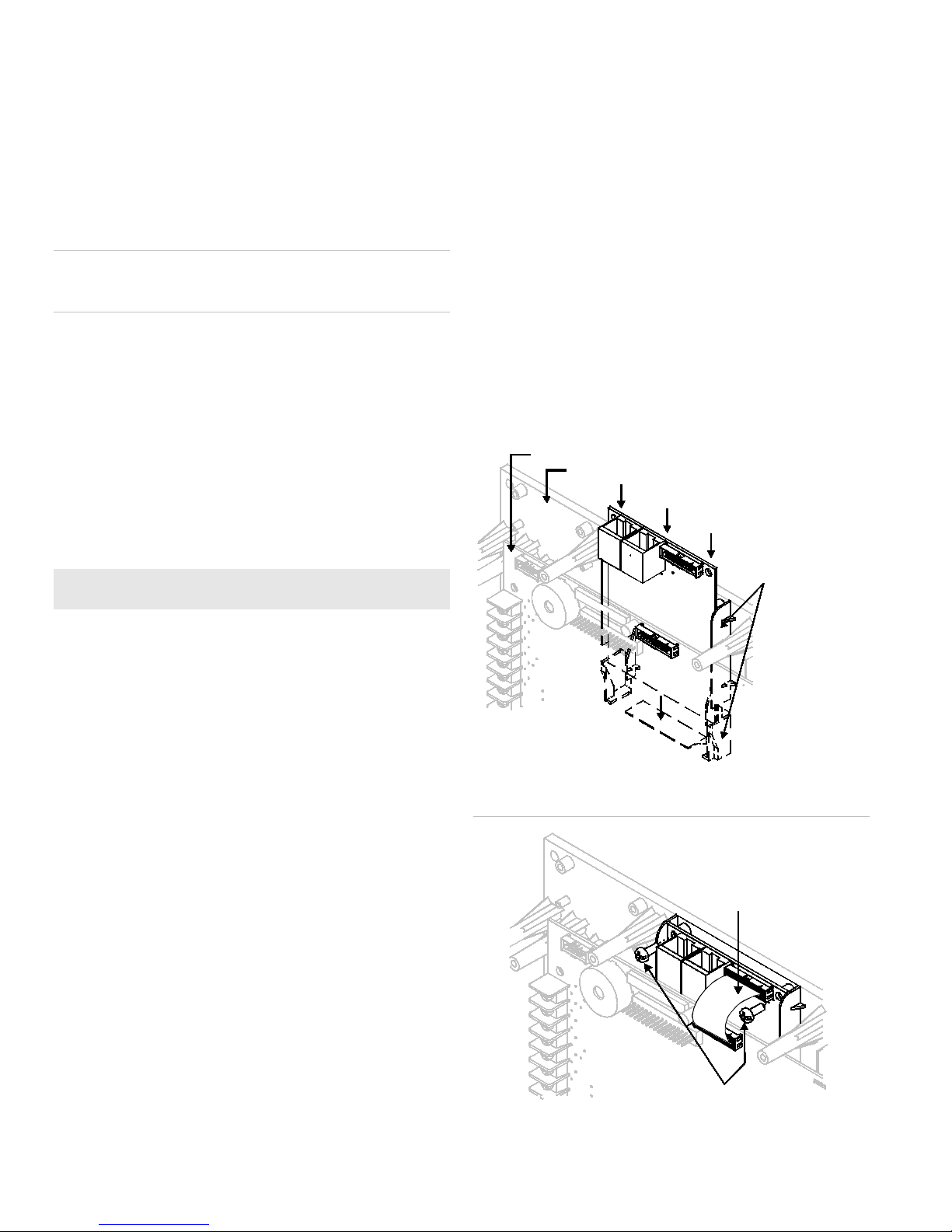
Figure 1: Slide the DACT into its slot
Installation
The DACT is installed on the plastic assembly and connects to
the main circuit board via a ribbon cable.
To install the DACT:
1. Power down the panel and disconnect the batteries.
2. Locate the dialer card slot on the plastic assembly behind
the main circuit board and connector J8 on the main circuit
board (at the top-center of the main board).
3. Slide the DACT into the slot on the plastic assembly as
shown in the diagram.
4. Attach the DACT to the plastic assembly using two #6
plastite screws as shown in the diagram.
5. Connect the ribbon cable (P/N 7140188) from the DACT to
connector J8 on the main circuit board.
6. Connect the phone lines. See “Wiring.”
7. Power up the panel and connect the batteries.
Figure 2: Screw the DACT in place and connect the ribbon cable
© 2013 UTC Fire & Security. All rights reserved. 1 / 8 P/N 3101099 • REV 03 • REB 25JAN13
Page 2

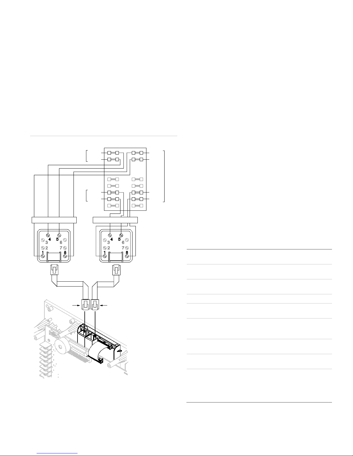
Wiring
Tip
Ring
Tip
Ring
Tip
Ring
Tip
Ring
Prot ected pr em i ses
punch down block
TELCO
Line 2
TELCO
Line 1
PBX
RJ-31X block
(supplied by installer)
8-positi on, 4-condu ct or
modular cords
(supplied by installer)
LIN E 2
2
3
4 5
7
6
81
LIN E 1
2
3
4 5
7
6
81
J1
J4
Telephone protector Telephone protector
Phone line type
Phone line connector
Communication f
Operating voltage
Operating current
FCC registration number
Industry Canada
Registration number
Ringer equivalence
number
Operating environment
Testing
The dialer phone lines connect to connectors on the dialer's
main circuit board. Phone line 1 connects to connector J1 and
phone line 2 connects to connector J4.
The card typically connects to an RJ-31X block using an
8-position, 4-conductor modular cord. Wire the RJ-31X block
as shown below.
Note: Install a listed secondary telephone protector between
the telco network and the SA-DACT card. The SA-DACT card
must be the next piece of equipment that connects to the
telephone company (TELCO) telephone lines.
Figure 3: SA-DACT wiring
A dialer test is a test of the telephone line for each dialer
account. When a dialer is tested, a normal or abnormal test
message (depending on the state of the system) is sent to the
selected account. If the dialer is set up for dual line operation,
a test message is sent to both lines regardless of the success
of the transmission for either account.
Note: Before conducting a test, configure the dialer’s accounts
for proper operation.
To conduct a dialer test:
1. Press the control panel's Menu button.
2. Choose Test.
3. Choose Dialer.
4. Select the account that you want to test.
5. Press Enter.
Note: The test message is sent to the CMS account that
you selected. For verification of the CMS account
receiving the test message, you must be in contact with
the CMS account during the test. Nothing is displayed on
the LCD display.
6. Press Cancel to return to the previous menu.
– or –
Press the Menu button to exit menu mode.
Specifications
ormats Contact ID (SIA DC-05)
24 VDC
Temperature
Humidity
One or two loop-start lines on a public,
switched network
RJ-31/38X (C31/38X)
Standby/Alarm: 41 mA
Max.: 100 mA
GESAL01BSADACT
3944A-SADACT
0.1B
32 to 120°F (0 to 49°C)
0 to 93% RH, noncondensing at 90°F
(32°C)
2 / 8 P/N 3101099 • REV 03 • REB 25JAN13
Page 3

Compatibility
Receiver
Ademco
FBII
Osborne
Radionics
Silent Knight
Sur
The dialer is listed for use with the following DACRs.
Models Formats
685 Contact ID
CP220 Contact ID
-Hoffman
D6600 Contact ID
9500, 9800 Contact ID
-Gard
OH2000 and
OH2000E (with a
OH2000E-LC line
card installed)
MLR1, MLR2, MCDI
TLR, TLR+, SG-SLR,
MLR2000
Contact ID
Contact ID
FCC information
Cautions
• To ensure proper operation, this dialer must be installed
according to the enclosed installation in str u ctio ns. To
verify that the dialer is operating properly and can
successfully report an alarm, it must be tested immediately
after installation, and periodically thereafter, according to
the enclosed test instructions.
• In order for the dialer to be able to seize the phone line to
report an alarm or other event when other customer
equipment (telephone, answering system, computer
modem, etc.) connected to the same line is in use, the
dialer must be connected to a properly installed RJ-31X
jack. The RJ-31X jack must be connected in series with,
and ahead of, all other equipment attached to the same
phone line. Series installation of an RJ-31X jack i s
depicted in the wiring diagram. If you have any questions
concerning these instructions, you should consult your
telephone company or a qualified installer.
Testing
When programming emergency numbers or making test calls
to emergency numbers, remain on the line and briefly explain
to the dispatcher the reason for the call. Perform programming
and testing activities in the off-peak hours, such as early
morning or late evenings.
Compliance
dialer contains, among other information, a product
identifier in the format US:AAAEQ##TXXXX. If requested,
this information must be provided to the telephone
company.
• The plug and jack used to connect the dialer to the
premises wiring and telephone network must comply with
the applicable FCC Part 68 rules and requirements
adopted by ACTA. The dialer must be connected to a
compliant RJ-31X or RJ-38X jack using a compliant cord.
If a modular telephone cord is supplied with the dialer, it is
designed to meet these requirements. See installation
instructions for details.
• A ringer equivalence number (REN) is used to determine
how many devices you can connect to a telephone line. If
the total REN value for all devices connected on a
telephone line exceeds that allowed by the telephone
company, the devices may not ring on an incoming call. In
most (but not all) areas the total REN value should not
exceed 5.0. To be certain of the total REN value allowed
on a telephone line, contact the local telephone company.
For products approved after July 23, 2001, the REN is part
of the product identifier in the format
US:AAAEQ##TXXXX. The digits ## represent the REN
without a decimal point. Example: 03 is an REN of 0.3. For
earlier products the REN is listed separately.
• If the dialer is harming the telephone network, the
telephone company will notify you in advance that
temporary discontinuance of service may be required. If
advance notice isn’t practical, the telephone company will
notify you as soon as possible. You will also be advised of
your right to file a complaint with the FCC, if you believe it
is necessary.
• The telephone company may make changes to its
facilities, equipment, operations, or procedures that could
affect the operation of the dialer. If this happens, the
telephone company will provide advance notice in order
for you to make necessary modifications to maintain
uninterrupted service.
• If you are experiencing problems with the dialer, contact
EST Technical Support for repair or warranty information.
If the dialer is harming the telephone network, the
telephone company may request that you disconnect the
dialer until the problem is resolved.
• The dialer contains no user serviceable parts. In case of
defects, return the dialer for repair.
• You may not connect the dialer to a public coin phone or a
party line service provided by the telephone co mpa ny .
• For equipment approved before July 23, 2001: This
dialer complies with Part 68 of the FCC rules. A label
attached to the dialer contains, among other information,
the FCC registration number and ringer equivalence
number (REN) for this equipment. If requested, this
information must be provided to the telephone company.
For equipment approved after July 23, 2001: This dialer
complies with Part 68 of the FCC rules and the
requirements adopted by the Administrativ e Co unc il for
Terminal Attachments (ACTA). A label attached to the
P/N 3101099 • REV 03 • REB 25JAN13 3 / 8
Industry Canada information
Note: The Industry Canada label identifies certified equipment.
This certification means that the equipment mee ts certa in
telecommunications network protective, operational, and safety
requirements. Industry Canada does not guarantee the
equipment will operate to the user’s satisfaction.
Before installing this equipment, users sho uld ens ure that it is
permissible to be connected to the facilities of the local
telecommunications company. The equipment must also be
Page 4
installed using an acceptable method of connection. The
Carte de circ uits im p rim é s prin c ip ale
Montage plastique
C arte du composeur
Fentes de la carte sur
montage plastique
Câble ruban au connecteur
J8 sur carte de circuits
imprimés principale
(centre supérieur)
J8
Vis plastie n 6
o
customer should be aware that compliance with the above
conditions may not prevent degradation of service in some
situations.
Repairs to certified equipment should be made by an
authorized Canadian maintenance facility designated by the
supplier. Any repairs or alterations made by the user to this
equipment, or equipment malfunctions, may give the
telecommunications company cau se to request the user
disconnect the equipment.
Caution: Users should not attempt to make conne cti ons
themselves, but should contact the appropriate electric
inspection authority, or electrician, as appropriate
Installation du DACT :
1. Coupez l’alimentation au panneau et débranchez les piles.
2. Localisez l’emplacement de la carte du composeur
automatique sur le montant en plastique derrière la carte
de circuits imprimés et le connecteur J3 (coin supérieur
gauche de la carte de circuits imprimés principale).
3. Glissez le DACT dans la coche du montant en plastique
comme indiqué dans le diagramme.
4. Attachez le DACT au montant en plastique à l’aide de vis
plastie no 6 comme indiqué dans le diagramme.
5. Branchez le câble ruban (P/N 7140188) du DACT au
connecteur J8 de la carte de circuits imprimés principale.
Users should ensure for their own protection that the ele ctri c al
ground connections of the power utility, telephone lines, and
internal metallic water pipe system, if present, are connected
together. This precaution may be particularly important in rural
areas.
Note: The Load Number (LN) assigned to each terminal device
denotes the percentage of the total load to be connected to a
telephone loop which is used by the device, to prevent
overloading. The termination on a loop may consist of any
combination of devices subject only to the requirements that
the sum of the Load Numbers of all the devices does not
exceed 100.
FR: Fiche D’Installation
Fonctionnement
Le SA-DACT établit les communications entre le panneau de
commande et le poste central au moyen d’une ligne
téléphonique. Le DACT transmet les modifications apportées à
l’état du système (événements) à un récepteur de
communication d’alarme numérique compatible par le
truchement d’un réseau téléphonique commuté public. Il
dresse une liste de message et les transmet selon un ordre de
priorité (alarme, supervision, trouble, désactivation, test,
surveillance et système). Le composeur automatique peut
signaler des événements uniques, double s ou séparé s à deux
comptes et numéros de téléphone différents. Son modem
permet également de télécharger en amont ou télécharger en
aval la configuration, l’historiq ue et l’état a ctuel du panneau sur
un ordinateur personnel qui exécute l’utilitaire de configuration.
Le modem utilise la ligne 1 seulement.
Remarque : Le SA-DACT est compatible avec le code
d’identité des CFP (CID) seulement.
Installation
Le DACT est installé sur le montant en plastique et est
branché à la carte de circuits imprimés principale à l’aide d’un
câble ruban.
6. Branchez les lignes téléphoniques. Voir la section
« Filage ».
7. Rétablissez l’alimentation au panneau et rebranchez les
piles.
Figure 1 : Glissez le DACT dans la fente
Figure 2 : Vissez le DACT en place et branchez le câble ruban
4 / 8 P/N 3101099 • REV 03 • REB 25JAN13
Page 5
Filage
Bloc de protection des lieux
TELCO
Ligne 2
Bloc RJ-31X
(fourni par l'installateur)
Ligne 2
Rallonges modulaires
à 8 positions et 4 conducteurs
(fournies par l'installateur
Ligne 1
J4
J1
Pointe
Anneau
Pointe
Anneau
PBX
Pointe
Anneau
TELCO
Ligne 1
Pointe
Anneau
Protecteur téléphonique
Protecteur téléphonique
Type de ligne
téléphonique
Connecteur
téléphonique
Formats de
communication
Tension de service
Courant opérationnel
N
Commission fédérale des
com
N
d’Industrie Canada
Numéro d’équivalence de
sonnerie
Environnement
opérationnel
Test
Les lignes du composeur automatique se branchen t aux
connecteurs sur la carte de circuits imprimés principale de ce
dernier. La ligne téléphonique 1 se branche au con nec teur J 1
et la ligne téléphonique 2 au connecteur J4.
Généralement, la carte se branche sur un bloc RJ-31X à l’aide
d’une rallonge modulaire à huit (8) positions et à quatre (4)
conducteurs. Câblez le bloc RJ-31X comme indiqué cidessous.
Remarque : Installez un protecteur télépho nique secondaire
entre le réseau de la compagnie de téléphone et la carte
SA-DACT. La carte SA-DACT doit être la pièce d’équipement
suivante qui se branche aux lignes téléphoniques de la
compagnie de téléphone (TELCO).
Figure 3 : Filage du SA-DACT
Un test de composition vérifie la ligne téléphonique de chacun
des comptes du composeur automatique. Lorsqu’un
composeur a été testé, un message normal ou anormal (selon
l’état du système) est envoyé au compte choisi. Si le
composeur est réglé pour une ligne double, un message de
test est envoyé aux deux lignes peu importe la qualité de la
transmission des deux comptes.
Remarque : Avant d’effectuer un essai, configurez les
comptes du composeur afin d’assurer un bon fonctionnement.
Tester le composeur automatique :
1. Appuyez sur le bouton Menu du panneau de commande.
2. Choisissez Test.
3. Choisissez Dialer (Composeur)
4. Sélectionnez le compte que vous désirez tester.
5. Appuyez sur Enter (Entrer)
Remarque : Le message test est envoyé au compte CMS
que vous avez sélectionné. Pour vérifier si le compte a
bien reçu le message test, vous devez être en
communication avec ce compte pendant le test. Rien
n’apparaît sur l’affichage DEL.
6. Appuyez sur Cancel (Annuler) pour revenir au menu
précédent.
- ou Appuyez sur le bouton Menu pour quitter le mode.
Fiche technique
de ligne
o
d’enregistrement de la
munications (CFC)
o
d’enregistrement
Température
Humidité
24 VDC
Lignes de départ à une ou deux boucles
d’un réseau public commuté.
RJ-31/38X (C31/38X)
Identification de contact (SIA DC-05)
En attente et alarme : 41 mA
Maximum : 100 mA
GESAL01BSADACT
3944A-SADACT
0.1 B
0 à 49 °C (32 à 120 °F)
0 à 93 % RH, non-condensation à 32 °C
(90 °F)
P/N 3101099 • REV 03 • REB 25JAN13 5 / 8
Page 6

Compatibilité
Récepteur
Ademco
FBII
Osborne
Radionics
Silent Knight
Sur
Le composeur est utilisable avec les DACR ci-dessous.
Modèles Formats
685
CP220
-Hoffman
D6600
9500, 9800
-Gard
OH2000 et OH2000E
(avec une carte de
ligne OH2000E-LC
installée)
MLR1, MLR2, MCDI
TLR, TLR+, SG-SLR,
MLR2000
Identification de
contact
Identification de
contact
Identification de
contact
Identification de
contact
Identification de
contact
Identification de
contact
Information de la FCC (Commission
fédérale des communications)
Avertissements
• Ce composeur doit être installé conformément aux
instructions d’installation incluses afin d’en assurer un bon
fonctionnement. Afin de vérif ie r que ce composeur
fonctionne et signale correctement une alar me, il doit être
testé conformément aux directives incluses,
immédiatement après son installation, puis
périodiquement par la suite.
• Le composeur doit être installé correctement à une fiche
RJ-31X de manière à ce qu’il puisse saisir une ligne
téléphone et signaler une alarme ou tout autre événement
lorsque d’autres équipements du client (téléphones,
répondeurs, modems, etc.) sont branchés et utilisent la
même ligne. La fiche RJ-31X doit être branchée en série
avec et en amont de tout autre équipement relié à la
même ligne téléphonique. L’installation en série d’une
fiche RJ -31X est décrite dans le diagramme du filage.
Pour toute question concernant ces instructions, consultez
votre compagnie de téléphone locale ou un installateur
qualifié.
Test
Lorsque vous programmez des numéros d’urgence ou que
vous effectuez des appels de test à des numéros d’urgence,
restez en ligne et expliquez brièvement au répartiteur la raison
de votre appel. Effectuez la programmation et les tests en
dehors des heures de pointe comme tôt le matin et tard en
soirée.
Conformité
• Pour les équipements approuvés avant le 23 juillet
2001 : Ce composeur est comporte à la partie 68 des
règlements de la FCC (Commission fédérale des
communications) Une étique tt e jointe au com pos eur
contient, entre autres choses, le numéro d’enregi stre men t
de la FC et le numéro d’équivalence de sonnerie (REN)
pour cet équipement. Sur demande, cette information doit
être fournie à la compagnie de téléphone.
Pour les équipements approuvés après le 23 juillet
2001 : Ce composeur est conforme à la partie 68 des
règlements de la FCC et aux exigences adoptées par
l’ACTA (Administrative Council for Terminal Attachments).
Une étiquette jointe au composeur contient, entre autres
choses, une identification américaine de produit qui
ressemble à ceci : AAAEQ##TXXXX. Sur demande, cette
information doit être fournie à la compagnie de téléphone.
• La fiche utilisée pour brancher le composeur au filage des
lieux et au réseau téléphonique doit être conforme à la
partie 68 des règlements de la FCC et aux exigences
adoptées par l’ACTA. Le composeur doit être branché à
une fiche RJ-31X ou RJ-38X au moyen d’une rallonge
électrique également conforme. Si une rallonge
téléphonique modulaire est fournie av ec le compos eur ,
elle est conçue pour être conforme à ces conditi ons .
Consultez les instructions d’installation pour les détails.
• Un numéro d’équivalence de sonnerie (REN) permet de
déterminer le nombre d’appareils que vous pouv ez
brancher à une ligne téléphonique. Si la valeur totale du
REN de tous les appareil s bra nché s à une ligne
téléphonique dépasse ce qui est permis par la compagnie
de téléphone, ceux-ci risquent de ne pas sonner lors d’un
appel entrant. Dans la plupart (mais pas dans tous) des
régions, la valeur totale du REN ne devrait pas dépasser
5,0. Afin de vous assurer de la valeur totale du REN sur
une ligne téléphonique, communiquez avec votre
compagnie de téléphone locale.
Pour les produits approuvés après le 23 juillet 2001, le
REN fait partie de l’identification américaine d’un produit et
ressemble à ceci : AAAEQ##TXXXX. Les chiffres (##)
représentent le REN sans point décimal. Exemple : 03 est
un REN de 0,3. Pour les produits fabriqués avant cette
date, le REN est inscrit séparément.
• Si le composeur endommage le réseau téléphonique, la
compagnie de téléphone vous avisera à l’avance qu’une
interruption temporaire du service peut s’avérer
nécessaire. Si un avis préalable n’est pas pratique, la
compagnie de téléphone vous avisera le plus tôt possible.
Vous serez également avisé de votre droit de porter
plainte auprès de la FCC si vous le jugez nécessaire.
• La compagnie de téléphone peut apporter des
modifications à ses installation s, son équi pem ent, se s
activités ou ses procédures et celles-ci peuv ent affe cter le
bon fonctionnement du composeur. Dans un tel cas, la
compagnie de téléphone vous informera au préalable de
manière à ce que vous puissiez apporter les modifications
nécessaires afin de ne pas interrompre le service.
6 / 8 P/N 3101099 • REV 03 • REB 25JAN13
Page 7

• Si vous éprouvez des diffi cul té s avec le compo seur,
communiquez avec le soutien technique de EST pour le
réparer ou obtenir de l’information en regard de la
garantie. Si le composeur endommage le réseau
téléphonique, la compagnie de téléphone peut vous
demander de le débrancher jusqu’à ce que le problème
soit réglé.
• Le composeur ne contient aucune pièce requérant un
entretien par l’utilisateur. En cas de défectuosité,
retournez le composeur pour être réparé.
• Vous ne devez pas brancher le composeur à une cabine
téléphonique publique ou à une ligne partagée fournie par
la compagnie de téléphone.
Information d’Industrie Canada
Remarque : L’étiquette d’Industrie Canada identifie les
équipements certifiés. Cette attestation signifie que
l’équipement satisfait à certaines exigences des réseaux de
télécommunication en matière de protection, de
fonctionnement et de sécurité. Industrie Canada ne garantit
pas que l’équipement fonctionnera à la satisfacti on de
l’utilisateur.
Avant de l’installer, les utilisateurs devraient s’assurer qu’ils ont
l’autorisation de se brancher aux installations de la compagnie
de téléphone locale. L’équipement doit également être installé
selon des méthodes de connexion acceptables. Le client
devrait être conscient que la conformité aux conditions
mentionnées ci-dessus n’empêchera pas la détérioration du
service en certaines situations.
Toute réparation à des équipements certifiés devrait être
effectuée par des établissements d’entretien canadiens
autorisés et reconnus par le fournisseur. Toute réparation ou
modification effectuée à cet équipement par l’utilisateur, ou
tout mauvais fonctionnement dudit équipement peut être une
cause de débranchement de service par la compagnie de
téléphone.
Avertissement : Les utilisateurs ne devraient pas effectuer
eux-mêmes des branchements, mais communiquer avec les
autorités d’inspection électrique appropriées ou un électricien,
s’il y a lieu.
Pour leur propre protection, les utilisateurs devraient s’assurer
que les connexions de mise à la terre du service public
d’électricité, les lignes téléphoniques et les circuits
hydrauliques métalliques internes, s’ils existent, sont branchés
ensemble. Cette précaution peut s’avérer tout particulièrement
importante en milieu rural.
Remarque : L’indice de charge (IC) assigné à chaque terminal
indique le pourcentage de la charge totale à brancher sur une
boucle téléphonique utilisée par l’appareil afin de prévenir
toute surcharge. L’impédan ce termi nal e d’une boucle peut
consister en une combinaison de dispositifs assujettis
seulement aux exigences que la somme des indices de charge
de tous ces dispositifs ne dépasse pas 100.
P/N 3101099 • REV 03 • REB 25JAN13 7 / 8
Page 8

8 / 8 P/N 3101099 • REV 03 • REB 25JAN13
 Loading...