

Page 1

Instruction Manual
RV3, RV5, RV8 and RV12 Rotary Vane Pumps
A652–01–880
Issue Y
A 65X-YY-ZZZ
Pump Type Variant Motor Description
X YY ZZZ
2 = RV3 01 to 99 903 = 220-240 V, 50/60 Hz, Single phase
3 = RV5 904 = 100/200 V, 50/60 Hz, Single phase
4 = RV8 905 = 200-230/380-460 V, 50/60 Hz, Three phase
5 = RV12 906 = 110-115/120 V 50/60 Hz, Single phase
925 = 200-230/380-460 V, 50/60 Hz, Three phase
Original Instructions
Page 2

This product has been manufactured under a quality management system certified to ISO 9001:2015.
P200-00-540 Issue L
2006/42/EC
Machinery directive
2014/35/EU
Low voltage directive (LVD) as applicable to electrical sub-assemblies
2011/65/EU
Restriction of certain hazardous substances (RoHS) directive
EN 1012-2:1996
+A1:2009
Compressors and vacuum pumps. Safety requirements. Vacuum pumps
EN 60034-1:2010
Rotating electrical machines. Rating and performance
EN 61010-1:2010 *
Safety requirements for electrical equipment for measurement, control and laboratory use.
General requirements
CSA-C22.2 No.77-2014#
Motors with inherent overheating protection
CSA-C22.2 No.100-2014#
Motors and generators
CSA-C22.2
No.61010-1-12
Safety requirements for electrical equipment for measurement, control and
laboratory use – Part 1: General requirements
UL61010-1
3rd Edition
Safety requirements for electrical equipment for measurement, control and
laboratory use – Part 1: General requirements
Mr Ian Keech
Declaration of Conformity
Edwards Ltd,
Innovation Drive,
Burgess Hill,
West Sussex,
RH15 9TW, UK
The following product
A65X – YY – ZZZ
Pump type Variant Motor descri ption
X YY ZZZ
2 = RV3 01 to 99 903 = 220-240V, 50/60Hz, Single phase
3 = RV5 904 = 100/200V, 50/60Hz, Single phase
4 = RV8 905 = 200-230/380-460V, 50/60Hz, Three phase
5 = RV12 906 = 110-115/120, 50/60Hz, Single phase
925 = 200-230/380-460V, 50/60Hz, Three phase set to low voltage
Is in conformity with the relevant requirements of European CE legislation:
Based on the relevant requirements of harmonised standards:
*1-phase pumps only The pumps comply with EN 61010-1 when installed in accordance with the instruction manual supplied
with the pumps.
The product also complies with the following:
#1-phase pumps only Canadian Standards Authority and Underwriters Laboratory
This covers all product serial numbers from the date of this declaration onwards.
19.03.2018, Burgess Hill
Vice President Engineerin g, Hi gh V ac uu m Division
Date and Place
This declaration is based on the requirements of EN ISO 17050-1 and the relevant directives.
Page 3

P200-10-019
Issue D
Material Declaration
In accordance with the requirements of the Chinese regulatory requirement on the Ma nagement Methods for the
Restriction of the Use of Hazardous Substances in Electrical and Electronic Products Order No. 32 (also known as
‘China RoHS2’) and SJ/T 11364 Marking for the Restricted Use of Hazardous Substances in Electronic and Electrical
Products:
Product Labels
Product Product Label Meaning
This product contains hazardous substances in at least one of the
All pumps in the
list below
Pump Type Pump Size
RV Pumps RV3,5,8,12, E Lab, nRVi
EM Small Pumps E2M0.7, 1.5, E1M18, E2M18, 28, 30, nE2M40i
nEXT Pumps nEXT 85, 240, 300, 400, Splitflow
nXDS pumps nXDS 6, 10, 15, 20
EXT pumps EXT75DX
XDS pumps XDS35, 46, 100
Diaphragm XDD 1, D lab
Turbo Pump Carts T station, nEXPT, nEXT station
部件名称
Part name
铸铝
Cast Aluminium
铜管管件
Brass pipe Fittings
铜接头
Brass Connectors
2020
铅
Lead
(Pb)
Mercury
X O O O O O
X O O O O O
X O O O O O
homogeneous materials used which are above the limit requirement
in GB/T 26572 as detailed in the declaration table below.
These parts can safely be used for the environmental protection use
period as indicated.
材料成分声明
Materials Content Declaration
质
汞
(Hg)
镉
Cadmium
(Cd)
危险物
六价铬
Hexavalent
Chromium
(Cr VI)
多溴联苯
Polybrominated
biphenyls (PBB)
Polybrominated
diphenyl ethers
多溴二苯醚
(PBDE)
O: 表示该有害物质在该部件的所有均质材料中的含量低于 GB/T 26572 标准规定的限量要求。
O: Indicates that the hazardous substance contained in all of the homogeneous materials for this part is below
the limit requirement in GB/T 26572.
X: 表示该有害物质在该部件的至少一种均质材料中的含量超出 GB/T26572 标准规定的限量要求。
X: Indicates that the hazardous substance contained in at least one of the homogeneous materials used for
this part is above the limit requirement of GB/T26572.
NOTES: These products are EU RoHS compliant, the following Exemptions apply:
6(b) Lead as an alloying element in aluminium containing up to 0.4% by weight.
6(c) Copper alloy containing up to 4% lead by weight
Packaging Information
Pallet Over-shipper Protection Pieces Support Braces
NWNW
Recyclable Natural Wood Recyclable Cardboard Recyclable Polypropylene Recyclable Mild Steel
Page 4

This page has been intentionally left blank.
Page 5

A652–01–880 Issue Y
Contents
Section Page
1 Introduction .......................................................................................1
1.1 Scope and definitions ...................................................................................................1
1.2 ATEX directive implications ............................................................................................2
1.3 Description ................................................................................................................4
1.4 Performance modes and controls .....................................................................................4
1.4.1 Mode selector ............................................................................................................4
1.4.2 Gas-ballast control ......................................................................................................5
1.5 Construction .............................................................................................................. 5
2 Technical data ....................................................................................7
2.1 Operating and storage conditions .....................................................................................7
2.2 Performance .............................................................................................................. 7
2.2.1 General .................................................................................................................. ..7
2.2.2 Performance characteristics ..........................................................................................11
2.3 Mechanical data .........................................................................................................12
2.4 Noise and vibration data ...............................................................................................12
2.5 Lubrication data ........................................................................................................12
2.6 Electrical data: single-phase pumps .................................................................................14
2.6.1 Electrical cables ........................................................................................................14
2.7 Electrical data: three-phase pumps .................................................................................15
Contents
3 Installation ....................................................................................... 17
3.1 Safety .....................................................................................................................17
3.2 System design considerations .........................................................................................17
3.3 Unpack and inspect .....................................................................................................18
3.4 Locate the pump ........................................................................................................18
3.5 Fill the pump with oil ..................................................................................................18
3.6 Electrical installation: single-phase pumps .........................................................................19
3.6.1 Check and configure the motor .......................................................................................19
3.6.2 Connect the pump to the electrical supply .........................................................................19
3.6.3 Check the direction of rotation .......................................................................................19
3.7 Electrical installation: three-phase pumps .........................................................................21
3.7.1 Check and configure the motor .......................................................................................21
3.7.2 Connect the pump to the local electrical supply ..................................................................21
3.7.3 Check the direction of rotation .......................................................................................23
3.8 Inlet and outlet connections ..........................................................................................23
3.9 Leak-test the system ...................................................................................................24
4 Operation ........................................................................................ 25
4.1 ATEX directive implications ...........................................................................................25
4.1.1 Introduction .............................................................................................................25
4.1.2 Flammable/pyrophoric materials ....................................................................................25
4.1.3 Gas purges ...............................................................................................................26
4.2 How to use the pump controls ........................................................................................26
4.2.1 Introduction .............................................................................................................26
4.2.2 Mode selector ...........................................................................................................27
4.2.3 Gas-ballast control .....................................................................................................27
4.3 Start-up procedure .....................................................................................................28
4.4 To achieve ultimate vacuum ..........................................................................................28
4.5 To pump condensable vapours ........................................................................................29
4.6 To decontaminate the oil ..............................................................................................29
cg/01/18
© Edwards Limited 2018. All rights reserved. Page i
Edwards and the Edwards logo are trade marks of Edwards Limited.
Page 6

A652–01–880 Issue Y
Contents
4.7 Unattended operation ..................................................................................................29
4.8 Shut-down ................................................................................................................30
5 Maintenance ..................................................................................... 31
5.1 Safety information ......................................................................................................31
5.2 Maintenance plan .......................................................................................................32
5.3 Check the oil-level ......................................................................................................32
5.4 Replace the oil ..........................................................................................................33
5.5 Inspect and clean the inlet-filter .....................................................................................33
5.6 Inspect and clean the gas-ballast control ...........................................................................34
5.7 Clean the oil-level sight-glass .........................................................................................35
5.8 Clean the motor fan-cover and enclosure ..........................................................................36
5.9 Clean and overhaul the pump .........................................................................................36
5.10 Fit new blades ...........................................................................................................36
5.11 Test the motor condition ..............................................................................................36
5.12 Fault-finding .............................................................................................................36
5.12.1 Introduction .............................................................................................................36
5.12.2 The pump has failed to start ..........................................................................................36
5.12.3 The pump has failed to achieve the specified performance (has failed to reach ultimate vacuum) ......37
5.12.4 The pump is noisy .......................................................................................................37
5.12.5 The pump surface temperature is above 100°C ...................................................................37
5.12.6 The vacuum is not fully maintained after the pump is switched off ...........................................37
5.12.7 The pumping speed is poor ............................................................................................38
5.12.8 There is an external oil leak ..........................................................................................38
6 Storage and disposal ........................................................................... 39
6.1 Storage ...................................................................................................................39
6.2 Disposal ...................................................................................................................39
7 Service and spares .............................................................................. 41
7.1 Introduction .............................................................................................................41
7.2 Service ....................................................................................................................41
7.3 Spares .....................................................................................................................41
7.4 Accessories ...............................................................................................................43
7.4.1 Introduction .............................................................................................................43
7.4.2 Inlet catchpot ...........................................................................................................43
7.4.3 Inlet dust filter ..........................................................................................................43
7.4.4 Inlet desiccant trap .....................................................................................................43
7.4.5 Inlet chemical trap .....................................................................................................44
7.4.6 Foreline trap .............................................................................................................44
7.4.7 Outlet mist filter ........................................................................................................44
7.4.8 Gas-ballast adaptor .....................................................................................................44
7.4.9 Gravity oil drain kit .....................................................................................................44
7.4.10 Oil drain-extension .....................................................................................................44
7.4.11 Exhaust nozzle kit ......................................................................................................44
7.4.12 Vibration isolators ......................................................................................................44
7.4.13 Solenoid operated gas-ballast valve .................................................................................44
7.4.14 Solenoid operated pipeline valve ....................................................................................44
8 PFPE-prepared RV pumps ...................................................................... 47
8.1 Summary .................................................................................................................47
8.2 Installation ...............................................................................................................47
8.3 Operation ................................................................................................................47
8.4 Maintenance .............................................................................................................47
For return of equipment, complete the HS Forms at the end of this manual.
Page ii © Edwards Limited 2018. All rights reserved.
Edwards and the Edwards logo are trade marks of Edwards Limited.
Page 7

A652–01–880 Issue Y
Illustrations
Figure Page
1 The RV pump .............................................................................................................3
2 Performance characteristics in High Vacuum mode (pumping speed against inlet pressure) ...............11
3 Dimensions (mm) ........................................................................................................13
4 Motor voltage configuration: single-phase pumps .................................................................20
5 Three-phase electrical connections: 200–230 V ....................................................................22
6 Three-phase electrical connections: 380–460 V ....................................................................22
7 Inlet-filter assembly ....................................................................................................33
8 Gas-ballast control assembly ..........................................................................................34
9 Sight-glass assembly ....................................................................................................35
10 Accessories ...............................................................................................................45
Tables
Table Page
Contents
1 Operating and storage conditions .....................................................................................7
2 General performance data ............................................................................................. 7
3 Performance data: High Vacuum mode ..............................................................................8
4 Performance data: High Throughput mode .......................................................................... 9
5 Performance characteristics ..........................................................................................10
6 Mechanical data .........................................................................................................12
7 Noise and vibration data ...............................................................................................12
8 Lubrication data ........................................................................................................12
9 Electrical data (single-phase pumps with Part Numbers ending in -903 or -906) .............................14
10 Electrical data (single-phase pumps with Part Numbers ending in -904) ......................................14
11 Recommended regional supply protection ..........................................................................14
12 Recommended cord sets ...............................................................................................15
13 Electrical data (three-phase pumps with Part Numbers ending in -905) .......................................15
14 Maintenance plan .......................................................................................................32
15 Spares and maintenance kits ..........................................................................................42
16 Accessory item numbers ...............................................................................................43
Associated publications
Publication title Publication number
Vacuum pump and vacuum system safety P400–40–100
Trademark credits
Fomblin® is a registered trademark of Ausimont SpA.
© Edwards Limited 2018. All rights reserved. Page iii
Edwards and the Edwards logo are trade marks of Edwards Limited.
Page 8

A652–01–880 Issue Y
This page has been intentionally left blank.
Page iv © Edwards Limited 2018. All rights reserved.
Edwards and the Edwards logo are trade marks of Edwards Limited.
Page 9

A652–01–880 Issue Y
1 Introduction
1.1 Scope and definitions
This manual provides installation, operation and maintenance instructions for the Edwards RV3, RV5, RV8 and RV12
Rotary Vane Pumps. The pump must be used as specified in this manual.
Read this manual before installing and operating the pump. Important safety information is highlighted as WARNING
and CAUTION instructions; these instructions must be obeyed. The use of WARNINGS and CAUTIONS is defined below.
WARNING
Warnings are given where failure to observe the instruction could result in injury or death to
people. The actual symbol shown varies according to the hazard.
CAUTION
Cautions are given where failure to observe the instruction could result in damage to the equipment, associated
equipment and/or process.
Introduction
The units used throughout this manual conform to the SI international system of units of measurement.
The following warning labels may be present on the pump and used throughout the product documentation:
Warning – an appropriate safety instruction should be followed or a caution to a potential hazard exists.
Warning – dangerous voltage. Indicates hazards arising from dangerous voltages.
Warning – hot surfaces. To indicate that the marked item can be hot and should not be touched without
taking precautions.
Warning – heavy object. Indicates the potential risk of physical injury and requires suitable lifting
equipment to move.
Warning – use protective equipment. Indicates that protective equipment must be used.
© Edwards Limited 2018. All rights reserved. Page 1
Edwards and the Edwards logo are trade marks of Edwards Limited.
Page 10

A652–01–880 Issue Y
Introduction
1.2 ATEX directive implications
This equipment is designed to meet the requirements of Group II Category 3 equipment in accordance with
Directive 94/9/EC of the European Parliament and the Council of 23rd March 1994 on the approximation of
the laws of the Member States concerning equipment and protective systems intended for use in potentially
explosive atmospheres. (The ATEX Directive).
The ATEX Category 3 applies in respect of potential ignition sources internal to the equipment. An ATEX Category
has not been assigned in respect of potential ignition sources on the outside of the equipment as the equipment
has not been designed for use where there is an external potentially explosive atmosphere.
There is no potential source of ignition within the pump during normal operation but there may be potential
sources of ignition under conditions of predicted and rare malfunction as defined in the Directive. Accordingly,
although the pump is designed to pump flammable materials and mixtures, operating procedures should ensure
that under all normal and reasonably predicted conditions, these materials and mixtures are not within
explosive limits. Category 3 is considered appropriate for the avoidance of ignition in the case of a rare
malfunction which allows flammable materials or mixtures to pass through the pump while within their explosive
limits.
When flammable or pyrophoric materials are present within the equipment:
Do not allow air to enter the equipment.
Ensure that the system is leak tight.
For further information, please contact Edwards: refer to the Addresses page at the end of this manual for
details.
Page 2 © Edwards Limited 2018. All rights reserved.
Edwards and the Edwards logo are trade marks of Edwards Limited.
Page 11

Figure 1 - The RV pump
A652–01–880 Issue Y
Introduction
1. Electrical inlet-connector
2. Voltage indicator
3. Lifting handle
4. NW25 inlet-port
5. Gas-ballast control
6. Oil filler-plug
7. NW25 outlet-port
*
RV3 and RV5 pumps only; a lifting bracket is
fitted to RV8 and RV12 pumps.
Note: Single-phase RV3/RV5 pump shown.
*
8. Oil-level sight-glass
9. Oil drain-plug
10.Rubber feet (4 off)
11.Mode selector
12.On-off switch
13.Motor fan-cover
14.Correct direction of rotation
†
Single-phase pumps only.
†
© Edwards Limited 2018. All rights reserved. Page 3
Edwards and the Edwards logo are trade marks of Edwards Limited.
Page 12

A652–01–880 Issue Y
Introduction
1.3 Description
The Edwards RV rotary vane pump is shown in Figure 1. Refer to Figure 1 for item numbers in brackets in the following
descriptions. The RV pumps are two-stage, oil-sealed, sliding-vane vacuum pumps. The pump has NW25 inlet (4) and
outlet (7) ports, a gas-ballast control (5) and a mode selector (11). When the pump is switched off, an inlet-valve
seals the inlet and prevents the suck-back of air and oil into the vacuum system.
The RV3 and RV5 pumps have a retractable lifting handle (3). The RV8 and the RV12 pumps are fitted with a lifting
bracket for use with suitable lifting equipment.
An oil-pump delivers pressurised oil to the vacuum pumping mechanism in the RV pump. The oil level and condition
can be inspected in the oil-box through a sight-glass (8). Two oil filler-plugs (6) and an oil drain-plug (9) are provided
on the oil-box.
The pump mechanism is driven directly by a single-phase or three-phase electric motor through a flexible
motor-coupling. The motor is totally enclosed and is cooled by the motor cooling-fan which directs air along the
motor fins. The pumps are cooled by an additional fan attached to the motor-coupling.
Single-phase motors are fitted with an on/off switch (12) and a thermal overload device. When the motor is too hot,
the thermal overload device switches off the pump. The thermal overload device has an automatic reset; when the
motor cools down, the device resets and (unless suitable control equipment has been incorporated which must be
manually reset: see Section 3.6.2 and Section 3.7.2), the motor will restart.
As of the end of 2009 improved motors have been fitted to RV pumps. These motors benefit from being fitted with
an aluminium terminal box and externally accessible voltage change-over switches. The introduction of these motors
has resulted in the range of motors covering all voltage and frequency conditions being reduced from four variants
to two. All motors are interchangeable and pump performance is not affected.
The pump is mounted on a base plate on rubber feet (10). Details of suitable vibration isolators and other accessories
are provided in Section 7.
Refer to Section 8 for additional information if the pump is PFPE-prepared.
1.4 Performance modes and controls
The pump has two controls: the mode selector (11) and the gas-ballast control (5). Six possible combinations of these
controls allow for a wide choice of operating characteristics to optimise the performance of the pump for a given
application.
1.4.1 Mode selector
The mode selector has two positions; refer to Section 4.2 to select these positions. Throughout the rest of this
manual, the following convention is used:
The High Vacuum mode is specified by the symbol.
The High Throughput mode is specified by the symbol.
With the mode selector set to High Vacuum mode , pressurised oil is fed to the low vacuum stage only. In this mode
of operation, the pump provides the best possible ultimate vacuum.
With the mode selector set to High Throughput mode
stages. In this mode of operation, the pump can sustain long-term high inlet pressures.
, pressurised oil is fed to the high vacuum and low vacuum
Page 4 © Edwards Limited 2018. All rights reserved.
Edwards and the Edwards logo are trade marks of Edwards Limited.
Page 13

A652–01–880 Issue Y
1.4.2 Gas-ballast control
To pump high vapour loads, gas-ballast is delivered into the pump to prevent condensation of the vapour carried by
the pumped gases.
Air can be introduced to the low vacuum stage through the gas-ballast valve. Alternatively, an inert gas such as
nitrogen can be supplied through a suitable external valve.
The gas-ballast control has three positions:
Closed (position ‘0’)
Low flow (position ‘I’)
High flow (position ‘II’).
1.5 Construction
The pump-shafts and rotors are made of high-grade cast-iron. The pump-body and oil-box are made from
cast-aluminium. All surfaces of the pump which are exposed to the pumped gases are free from copper, zinc and
cadmium.
Other materials of construction include fluorocarbon elastomer, nitrile, silicon, chemically-resistant polymers, nickel
and stainless steel.
Introduction
© Edwards Limited 2018. All rights reserved. Page 5
Edwards and the Edwards logo are trade marks of Edwards Limited.
Page 14

A652–01–880 Issue Y
This page has been intentionally left blank.
Page 6 © Edwards Limited 2018. All rights reserved.
Edwards and the Edwards logo are trade marks of Edwards Limited.
Page 15

2 Technical data
2.1 Operating and storage conditions
Table 1 - Operating and storage conditions
Parameter Reference data
Ambient temperature range (operation) +12 to +40°C
Ambient temperature range (storage) –30 to +70°C
Normal surface temperature of the pump-body * +50 to +70°C
Maximum humidity (operation) 90% RH
Maximum altitude (operation) 2000 m
Pollution degree 2
Installation category II
Area of use Indoor use
* At ultimate vacuum, with ambient temperature of 20°C.
A652–01–880 Issue Y
Technical data
2.2 Performance
2.2.1 General
Note: In Table 2 and Table 3, total pressures have been measured by a capacitance diaphragm gauge on a vacuum
chamber without a cold trap, as specified by Pneurop Standard 6602 (1979).
Table 2 - General performance data
Parameter Reference data
High Vacuum mode performance See Table 3
High Throughput mode
Suckback protection 1 x 10
Maximum initial pressure rise with no gas-ballast flow 1 x 10⁻¹ mbar, 10 Pa
Maximum displacement: m
50 Hz electrical supply
60 Hz electrical supply
Maximum pumping speed
(Pneurop 6602, 1979): m
50 Hz electrical supply
60 Hz electrical supply
Maximum permitted inlet pressure and gas-ballast inlet pressure
bar gauge 0.5 0.5 0.5 0.5
Pa 1.5 x 10
Maximum permitted outlet pressure
bar gauge 0.2 0.2 0.2 0.2
Pa 0.2 x 10
performance See Table 4
-5
mbar l s-1, 1 x 10⁻³ Pa l s
RV3 RV5 RV8 RV12
3 h-1
3.7
4.5
3 h-1
3.3
3.9
5
5
-1
5.8
5.0
5.1
6.2
1.5 x 1051.5 x 1051.5 x 10
0.2 x 1050.2 x 1050.2 x 10
9.7
11.7
8.5
10.0
14.2
17.0
12.0
14.2
5
5
© Edwards Limited 2018. All rights reserved. Page 7
Edwards and the Edwards logo are trade marks of Edwards Limited.
Page 16

Technical data
Page 8 © Edwards Limited 2018. All rights reserved.
Parameter Units
Gas-ballast control closed (position ‘0’)
Ultimate total pressure mbar 2 x 10
Pa 2 x 10
Gas-ballast control low flow (position ‘I’)
Ultimate total pressure mbar 3 x 10
Edwards and the Edwards logo are trade marks of Edwards Limited.
Pa3333
Gas-ballast flow l min
Maximum water vapour pumping rate kg h
Maximum water vapour inlet pressure mbar 27 18 16 11 10 7 7 5
Pa 2.7 x 10
Gas-ballast control high flow (position ‘II’)
Ultimate total pressure mbar 1.2 x 10
Pa 1.2 x 10
Gas-ballast flow l min
Maximum water vapour pumping rate kg h
Maximum water vapour inlet pressure mbar 80 54 50 32 38 34 32 28
Pa 8 x 10
Table 3 - Performance data: High Vacuum mode
HIGH VACUUM MODE
RV3 RV5 RV8 RV12
1-phase 3-phase 1-phase 3-phase 1-phase 3-phase 1-phase 3-phase
-3
-1
-2
-1
-1
-1
-1
0.06 0.04 0.06 0.04 0.06 0.04 0.06 0.04
0.22 0.12 0.22 0.12 0.22 0.20 0.29 0.25
5555
3
1.8 x 10
3
1.6 x 10
-1
1
14 14 16 16
3
5.4 x 10
3
5 x 10
2 x 10
2 x 10
3 x 10
3
1 x 10
1 x 10
3
-3
-1
-2
1.1 x 10
-1
1
3.2 x 10
3
3
1 x 10
3.8 x 10
-3
2 x 10
-1
2 x 10
-2
3 x 10
3
6 x 10
7 x 10
-2
2
7 x 10
66
3
3.4 x 10
3
3.2 x 10
2 x 10
2 x 10
3 x 10
2
6 x 10
3
-3
-1
-2
5 x 10
-2
2.8 x 10
A652–01–880 Issue Y
2
3
Page 17

© Edwards Limited 2018. All rights reserved. Page 9
Edwards and the Edwards logo are trade marks of Edwards Limited.
Table 4 - Performance data: High Throughput mode
HIGH THROUGHPUT MODE
Parameter Units
1-phase 3-phase 1-phase 3-phase 1-phase 3-phase 1-phase 3-phase
RV3 RV5 RV8 RV12
Gas-ballast control closed (position ‘0’)
Ultimate total pressure mbar 3 x 10
-2
3 x 10
-2
3 x 10
-2
3 x 10
Pa3333
Gas-ballast control low flow (position ‘I’)
Ultimate total pressure mbar 6 x 10
-2
6 x 10
-2
4 x 10
-2
4 x 10
Pa6644
Gas-ballast flow l min
Maximum water vapour pumping rate kg h
-1
-1
0.06 0.04 0.06 0.04 0.06 0.04 0.06 0.04
5555
Maximum water vapour inlet pressure mbar 27 18 16 11 10 7 7 5
Pa 2.7 x 10
3
1.8 x 10
3
1.6 x 10
3
1.1 x 10
3
1 x 10
3
7 x 10
2
7 x 10
2
Gas-ballast control high flow (position ‘II’)
Ultimate total pressure mbar 1.2 x 10
Pa 1.2 x 10
Gas-ballast flow l min
Maximum water vapour pumping rate kg h
-1
-1
0.22 0.12 0.22 0.12 0.22 0.20 0.29 0.25
14 14 16 16
-1
1
1 x 10
1 x 10
-1
1
-2
6 x 10
6 x 10
66
Maximum water vapour inlet pressure mbar 80 54 50 32 38 34 32 28
Pa 8 x 10
3
5.4 x 10
3
5 x 10
3
3.2 x 10
3
3.8 x 10
3
3.4 x 10
3
3.2 x 10
3
-2
-2
5 x 10
-2
2.8 x 10
2
3
A652–01–880 Issue Y
Technical data
Page 18

Technical data
Page 10 © Edwards Limited 2018. All rights reserved.
MODE
SELECTOR
POSITION
Closed (position ‘0’) Low flow (position ‘I’) High flow (position ‘II’)
High Vacuum mode Ultimate total pressure Ultimate total pressure Ultimate total pressure
mbar Pa mbar Pa mbar Pa
-3
2 x 10
2 x 10
Use for the best
ultimate pressure
Edwards and the Edwards logo are trade marks of Edwards Limited.
High Throughput mode
Ultimate total pressure Ultimate total pressure Ultimate total pressure
mbar Pa mbar Pa mbar Pa
-2
3 x 10
Use for continuous inlet pressure
above
50 mbar/5 x 10
3
Pa
Table 5 - Performance characteristics
-1
3 x 10
-2
Maximum water vapour pumping rate Maximum water vapour pumping rate
1-phase pumps 3-phase pumps 1-phase pumps 3-phase pumps
0.06 kg h
3 6 x 10⁻² (RV3/5)
4 x 10
-1
-2
(RV8/12)
Maximum water vapour pumping rate Maximum water vapour pumping rate
1-phase pumps 3-phase pumps 1-phase pumps 3-phase pumps
0.06 kg h
-1
GAS BALLAST CONTROL
3 1.2 x 10⁻¹ (RV3)
0.04 kg h
-1
6 (RV3/5)
4 (RV8/12)
0.04 kg h
-1
1.0 x 10
6 x 10
0.22 kg h-1 (RV3/5/8)
0.29 kg h
1.2 x 10
1.0 x 10
6 x 10
0.22 kg h-1 (RV3/5/8)
0.29 kg h
-1
(RV5)
-2
(RV8/12)
-1
(RV12)
-1
(RV3)
-1
(RV5)
-2
(RV8/12)
-1
(RV12)
1.2 x 10
1.0 x 10
1
1
6.0 (RV8/12)
-1
0.12 kg h
0.20 kg h
0.25 kg h
1.2 x 10
1.0 x 10
(RV3/5)
-1
(RV8)
-1
1
1
6.0 (RV8/12)
-1
0.12 kg h
0.20 kg h
0.25 kg h
(RV3/5)
-1
(RV8)
-1
A652–01–880 Issue Y
(RV3)
(RV5)
(RV12)
(RV3)
(RV5)
(RV12)
Page 19

A652–01–880 Issue Y
2.2.2 Performance characteristics
Note: The performance characteristics described below are for use with hydrocarbon oil.
The positions of the mode selector and the gas-ballast control define the performance characteristics of the pump.
These performance characteristics are listed fully in Table 3 and Table 4.
Table 5 gives the ultimate vacuum and maximum water vapour inlet pressure for each of the six possible
combinations of control positions. The curves 0, I, and II in Figure 2 show the relationship between inlet pressure and
pumping speed for High Vacuum mode
Figure 2 - Performance characteristics in High Vacuum mode (pumping speed against inlet pressure)
Technical data
© Edwards Limited 2018. All rights reserved. Page 11
Edwards and the Edwards logo are trade marks of Edwards Limited.
Page 20

A652–01–880 Issue Y
Technical data
2.3 Mechanical data
Table 6 - Mechanical data
Parameter Reference data
Dimensions See Figure 3
Degree of protection (IEC 34-5: 1981)
Single-phase pumps
Three-phase pumps
Maximum tilt angle 10°
Motor rotational speed
50 Hz electrical supply
60 Hz electrical supply
Maximum mass RV3 RV5 RV8 RV12
Pumps with motor, without oil 25.0 kg 25.0 kg 28.0 kg 29.0 kg
2.4 Noise and vibration data
IP44
IP54
1470 r min
1760 r min
-1
-1
Table 7 - Noise and vibration data
Parameter Reference data
Sound pressure
Single-phase pumps
Three-phase pumps
Vibration severity
Single-phase pumps
Three-phase pumps
*
Measured at ultimate vacuum 1 metre from the end of the pump to ISO 11201, High Vacuum mode ,
50 Hz operation.
†
Measured at the inlet port to ISO 2372 (1974)
*
48 dB (A)
50 dB (A)
†
Class 1C
Class 1C
2.5 Lubrication data
Note: Edwards Material Safety Data sheets for the rotary pump oils are available on request.
Table 8 - Lubrication data
Parameter Reference data
Recommended oil
Hydrocarbon-prepared pumps
PFPE-prepared pumps
Oil capacity RV3 RV5 RV8 RV12
Maximum 0.70 litres 0.70 litres 0.75 litres 1.00 litres
Minimum 0.42 litres 0.42 litres 0.45 litres 0.65 litres
*
To operate the pump when the ambient temperature is outside the limits specified in Section 2.1, or to
optimise the pump performance when pumping condensable vapours, a different oil may be needed.
*
Edwards Ultragrade 19
Krytox 1506 or Fomblin 06/6
Page 12 © Edwards Limited 2018. All rights reserved.
Edwards and the Edwards logo are trade marks of Edwards Limited.
Page 21

Figure 3 - Dimensions (mm)
A652–01–880 Issue Y
Technical data
A. Top view of single-phase pump
1. On-off switch (single-phase pumps only)
2. Lifting bracket (RV8 and RV12 pumps only; a
lifting handle is fitted to RV3 and RV5 pumps.)
Pump
RV3 430 429 158 225 127 29 78 230 120 37 32 –
RV5 430 429 158 225 127 29 78 230 120 37 32 –
RV8 470 469 158 225 161 35 78 230 120 37 32 261
RV12 490 489 158 225 181 35 78 230 120 37 32 261
*
Single-phase pumps.
†
Three-phase pumps.
© Edwards Limited 2018. All rights reserved. Page 13
Edwards and the Edwards logo are trade marks of Edwards Limited.
*
A
†
A
BCDEFGHI JK
B. Side view of single-phase pump
C. Side view of three-phase pump
D. Front view of single-phase pump
Page 22

A652–01–880 Issue Y
Technical data
2.6 Electrical data: single-phase pumps
Note: Edwards recommends using regional supply protection of the maximum ratings specified in Table 9
and Table 10. Protection of a higher rating must not be used.
The dual-voltage, dual-frequency motor is designed for a single-phase electrical supply and is suitable
for 50 Hz or 60 Hz operation. The motor can be manually switched between nominal supply voltages of 110–120 V
and 220-240 V (refer to Section 3.6.1).
When a cold pump is started, the motor will draw the start-up current shown in Table 9 and Table 10 for up to several
seconds. An appropriate rated and pre-approved time-lag fuse must be used to prevent unnecessary fuse failure
during pump start-up (in accordance with local and regional electrical codes). Within five minutes, as the oil in the
pump warms up, the current drawn will slowly reduce to the full load current specified in Table 9 and Table 10.
Table 9 - Electrical data (single-phase pumps with Part Numbers ending in -903 or -906)
Nominal
Pump
RV3, RV5, RV8 and
RV12
Table 10 - Electrical data (single-phase pumps with Part Numbers ending in -904)
Pump
RV3, RV5, RV8 and
RV12
Table 11 - Recommended regional supply protection
supply
(V)
220–240 50 450 3.4
230–240 60 550 3.0
110 50 450 6.8
115–120 60 550 6.9
Nominal
supply
(V)
200 50 450 4.2
200–210 60 550 4.1
100 50 450 8.3
100–105 60 550 8.0
Area Voltage (V) Rating (A)
UK 230 5
Europe 230 5
USA 110 13
Japan 100 13
Frequency
(Hz)
Frequency
(Hz)
Power
(W)
Power
(W)
Full load
current
(A)
Full load
current
(A)
2.6.1 Electrical cables
Recommended cord sets and fuses for regional requirements.
Page 14 © Edwards Limited 2018. All rights reserved.
Edwards and the Edwards logo are trade marks of Edwards Limited.
Page 23

Table 12 - Recommended cord sets
Description Rating Coupler type Item number
Cord set assembly, UK Cable style = H05VV-F, 3 x 1.0 mm
70 °C, maximum length of 2.0 metres
Plug type = BS1363 UK plug
Appliance coupler = IEC60320 style C14
Fuse type = BS1363 10 Amp fuse, to an
IEC60320 style
Cord set assembly, Europe Cable style = H05VV-F, 3 x 1.0 mm
70 °C, maximum length of 2.0 metres
Plug type = European Schuko VDE approved,
16 A 250 V rated with dual earthing contact
Appliance coupler = IEC60320 style C14
Cord set assembly,
USA/Canada (200 - 230 V)
Cable style = SJT, 3 x 14 AWG, 300 V,
90 °C, VW-1 maximum length of 3.0 metres
2
, 300 V,
2
, 300 V,
A652–01–880 Issue Y
Technical data
Straight entry A50505000
Straight entry A50506000
N/A
Plug type = NEMA, 6-15P plug
Appliance coupler = IEC60320 style C14
2.7 Electrical data: three-phase pumps
The dual-voltage, dual-frequency motor is designed for a three-phase electrical supply and is suitable for 50 Hz or
60 Hz operation. The motor can be manually configured for nominal supply voltages of 220–240 V or 380–460 V (refer
to Section 3.7.1). Pumps are supplied preset for nominal 380–460 V electrical supplies.
When a cold pump is started, the motor will draw the start-up current shown in Table 13 for up to 0.5 seconds. The
current will then reduce quickly as the motor reaches the rated rotational speed. Within 5 minutes, as the oil and
pump warms up, the current drawn will slowly reduce to a maximum of the full load current specified in Table 13.
When a warm pump is started, the motor will draw the start-up current shown in Table 13 for up to 0.5 seconds. The
current drawn will then immediately fall to the full load current.
Electrical short-circuit and ground-fault protection of the pump will be provided by fitting appropriate pre-approved
branch circuit protector or Class CC fuses of the values shown in Table 13 at the point of connection to the supply.
Table 13 - Electrical data (three-phase pumps with Part Numbers ending in -905)
Nominal
Pump
RV3 and RV5 200–220 50 250 1.7 10.2 2.5
RV8 and RV12 200–208 50 450 2.5 14.0 4.0
*
Observe requirements of local and regional electrical codes with respect to supply protection.
supply
(V)
200–230 60 300 1.7 10.2 2.5
380–415 50 250 1.0 5.7 2.5
460 60 300 1.0 7.0 2.5
200–230 60 550 2.9 12.0 4.0
380–415 50 450 1.5 9.0 2.5
460 60 550 1.5 8.7 2.5
Frequency
(Hz)
Power
(W)
Full load
current
(A)
Start-up
current
(A)
Recommended
supply
protection (A)
*
© Edwards Limited 2018. All rights reserved. Page 15
Edwards and the Edwards logo are trade marks of Edwards Limited.
Page 24

A652–01–880 Issue Y
This page has been intentionally left blank.
Page 16 © Edwards Limited 2018. All rights reserved.
Edwards and the Edwards logo are trade marks of Edwards Limited.
Page 25

3 Installation
3.1 Safety
Ensure that the installation technician is familiar with the safety procedures which relate to the
pump oil and the products handled by the pumping system.
Edwards recommends that a hydrocarbon-prepared RV pump is not used for pumping hazardous
substances. PFPE-prepared pumps are suitable for oxygen applications: refer to Section 8.
Obey the safety instructions in this Section and take note of appropriate precautions. If not, injury
to people and damage to equipment can result.
Prevent any part of the human body from coming into contact with the vacuum.
A652–01–880 Issue Y
Installation
WARNING
WARNING
Ensure that the RV pump is suitable for the application. If there is any doubt as to the suitability of the RV pump for
the application, refer to the Edwards guidelines on vacuum pump and vacuum system safety (see the Associated
publications at the end of the Contents list at the front of this manual), or contact Edwards for advice.
A suitably trained and supervised technician must install the RV pump. Obey the safety instructions listed below when
installing the pump, especially when connecting the pump into an existing system. Details of specific safety
precautions are given at the appropriate point in the instructions.
Wear the appropriate safety-clothing when coming into contact with contaminated components is
anticipated. Dismantle and clean contaminated components inside a fume cupboard.
Vent and purge the vacuum system before starting installation work.
Take suitable precautions to avoid the inhalation of oil mist and excessive skin contact with pump-oil, as
prolonged exposure can be harmful.
Disconnect the other components in the pumping system from the electrical supply so that they cannot be
operated accidentally.
Safely route any electrical supply cables to prevent a trip hazard.
3.2 System design considerations
Consider the following points when designing the pumping system:
Edwards recommends the use of a foreline vacuum isolation valve to allow the pump to warm up before
pumping condensable vapours or if a vacuum needs to be maintained when the pump is not running.
Avoid high levels of heat input to the pump from the process gases, otherwise the pump may overheat and
seize, and cause the motor thermal overload device to open.
If using the pump in a high ambient temperature with a high gas throughput, the temperature of the
pump-body may exceed 70°C. Edwards recommends the use of additional guarding to prevent contact with
hot surfaces under these conditions.
Make sure that the exhaust pipeline cannot become restricted. Maximum exhaust pressure is shown in
Table 2. If an exhaust-isolation valve is fitted, ensure the pump cannot be operated the pump with the valve
closed.
© Edwards Limited 2018. All rights reserved. Page 17
Edwards and the Edwards logo are trade marks of Edwards Limited.
Page 26

A652–01–880 Issue Y
Installation
Provide for a purge of inert gas when shutting down the pumping system, to dilute dangerous gases to safe
concentrations. A suitable gas ballast adaptor for introduction of purge gas into the pump is available as an
accessory (see Section 7.4.8). Contact the Edwards Application team for further advice on dilution
requirements if required.
3.3 Unpack and inspect
WARNING
The mass of the RV8 and RV12 pumps is approximately 29 kg.
For the RV8 and RV12 pumps attach the mechanical lifting equipment to the lifting bracket on the
pump. Slings do not need to be used to move the RV8 and RV12 pumps.
1. Remove all packing materials, and remove the pump from its packing-box.
2. Remove the protective covers from the inlet and outlet-ports and inspect the pump. If the pump is damaged,
notify the supplier and the carrier in writing within three days; state the Item Number of the pump together
with the order number and the supplier’ s invoice number. R etain all the packing materials for inspection. Do not
use the pump if it is damaged.
If the pump is not to be used immediately, replace the protective covers. Store the pump in the conditions, described
in Section 6.1. Refer to Section 6.2 for disposal of materials.
3.4 Locate the pump
The RV3 and RV5 pumps have a lifting handle enabling the pump to be moved by hand. If using mechanical lifting
equipment, do not attach the equipment to the handle; for stability, use slings around the motor and the pump-body.
Provide a firm, level platform for the pump. Locate the pump so that the oil-level sight-glass is visible and the oil
filler-plug, oil drain-plug, mode selector and gas-ballast control are accessible.
If the pump will be located inside an enclosure, to ensure the ambient temperature around the pump does not exceed
40°C, adequate ventilation is required at both ends of the pump. There must be a minimum space of 25 mm between
the pump and the enclosure walls.
3.5 Fill the pump with oil
WARNING
A hydrocarbon-prepared pump must not be used to process oxygen in concentrations greater than
25% in volume. As there is a risk of fire or explosion in the oil-box of the pump. PFPE-prepared
pumps are available: refer to Section 8.
Fill the pump with oil as described below. Refer to Section 2.5 for the recommended oil. Refer to Figure 1 for the
item numbers in brackets.
1. Remove one of the oil filler-plugs (6).
2. Pour oil into the pump until the oil-level just reaches the MAX mark on the bezel at the top of the sight-glass (8).
If the oil-level goes above the MAX mark, remove the drain-plug (9) and drain the excess oil from the pump.
3. After a few minutes, recheck the oil-level. If the oil-level is now below the MAX mark, pour more oil into the
pump.
4. Refit the oil filler-plug. Tighten the plug firmly by hand. Do not overtighten.
Page 18 © Edwards Limited 2018. All rights reserved.
Edwards and the Edwards logo are trade marks of Edwards Limited.
Page 27

A652–01–880 Issue Y
3.6 Electrical installation: single-phase pumps
3.6.1 Check and configure the motor
CAUTION
Ensure that the motor is correctly configured for the local electrical supply. If the pump is operated when the
motor is not correctly configured for the electrical supply, the motor will be damaged.
Refer to Figure 4 for the item numbers in brackets.
Ensure that the voltage shown on the voltage selector switch (3) in the motor-cover corresponds with the local
electrical supply voltage. If it does not, change the configuration of the pump-motor to match the local electrical
supply voltage; use the following procedure.
1. Undo the two retaining screws (6) securing the voltage selector switch cover (5).
2. Remove the voltage selector switch cover (5) and toggle the voltage selector switch (3) into the alternate
position.
3. Invert the voltage selector switch cover (5) and refit over the voltage selector switch (3).
4. Refit the two retaining screws (6).
Installation
3.6.2 Connect the pump to the electrical supply
WARNING
Ensure that the electrical installation of the RV pump conforms with local and national safety
requirements. The pump must be connected to a suitably fused and protected electrical supply
with a suitable earth point. For recommended cord sets refer to Section 2.4.
Note: To prevent automatic restart of the pump-motor if the electrical supply is restored after an electrical
supply failure, connect the pump to the electrical supply through suitable control equipment which must
be reset manually after an electrical supply failure.
1. Ensure that the on/off switch on the motor (Figure 4, item 4) is in the ‘off’ position.
2. Insert the moulded IEC connector at the end of the cable into the electrical inlet-connector on the motor
(Figure 4, item 2).
3. Connect the plug (if fitted) at the other end of the cable to the electrical supply. If a plug is not fitted, connect
the wires in the cable to the correct terminals of the electrical supply.
3.6.3 Check the direction of rotation
CAUTION
Ensure that the pump-motor rotates in the correct direction. If it does not, the pump and the vacuum system
can become pressurised.
Refer to Figure 1 for the item numbers in brackets.
1. Watch the motor cooling-fan through the motor fan-cover (13).
2. Use the on/off switch (12) to switch-on the electrical supply to the motor for a few seconds.
3. Check that the motor cooling-fan rotates in the correct direction (14) shown by the arrow on the motor
fan-cover. If the direction of rotation is incorrect, switch off the electrical supply immediately and contact the
supplier or Edwards for advice.
© Edwards Limited 2018. All rights reserved. Page 19
Edwards and the Edwards logo are trade marks of Edwards Limited.
Page 28

A652–01–880 Issue Y
Installation
Figure 4 - Motor voltage configuration: single-phase pumps
A. Top view of motor
B. View of voltage selector switch cover
C. View of On-off switch
Page 20 © Edwards Limited 2018. All rights reserved.
Edwards and the Edwards logo are trade marks of Edwards Limited.
1. Terminal box
2. Electrical inlet-connector
3. Voltage selector switch
4. On-off switch
5. Voltage selector switch cover
6. Retaining screws
7. Position 'I' (on)
8. Position '0' (off)
Page 29

A652–01–880 Issue Y
3.7 Electrical installation: three-phase pumps
3.7.1 Check and configure the motor
CAUTION
Ensure that the motor is correctly configured for the local electrical supply. If the pump is operated when the
motor is not correctly configured for the electrical supply, the motor will be damaged.
1. Remove the screws which secure the cover of the motor terminal-box. Remove the cover.
2. Remove the cable-gland from the inside of the terminal-box and fit the cable-gland to the cable leadthrough
hole in the side of the terminal-box.
3. Ensure that the motor is correctly configured for the local electrical supply. If necessary, reconfigure the links
(Figure 5 and Figure 6, item 1) to suit the local electrical supply:
For 200–230 V electrical supplies, the links must be configured as shown in Figure 5.
For 380–460 V electrical supplies, the links must be configured as shown in Figure 6.
3.7.2 Connect the pump to the local electrical supply
Installation
WARNING
Ensure that the electrical installation of the RV pump conforms with local and national safety
requirements. It must be connected to a suitably fused and protected electrical supply and a
suitable earth (ground) point.
Notes: To prevent automatic restart of the pump-motor if the electrical supply is restored after an electrical
supply failure, connect the pump to the electrical supply through suitable control equipment which
must be reset manually after an electrical supply failure.
Edwards recommends that the electrical supply is connected to the motor through a starter or circuit breaker which
has thermal over-current protection which can be adjusted to suit the full load current ratings shown in Table 13.
The fuse ratings in Table 13 are provided for guidance only. The supplier of the thermal over-current protection
device may specify different values to ensure correct operation of the fuse and the over-current protection device.
Ensure that the fuse used is suitable for the starting currents given in Table 13.
1. Remove the cover from the motor terminal box.
2. Remove the cable-gland from the inside of the terminal box and fit the cable-gland to the cable leadthrough
hole in the side of the terminal box. Using a tool this should be tightened to a torque of 3.75 Nm.
3. Pass the electrical supply cable through the cable-gland. The diameter of the electrical supply cable should be
in the range 7 to 11 mm.
4. Use insulated crimped connectors to connect the wires in the cable to the terminals U1, V1 and W1 and Earth
(ground) in the terminal-box as shown in Figure 5 and Figure 6. The earth (ground) terminal connection must be
tightened to a torque of 2.13 to 2.87 Nm.
5. Tighten the dome-shaped nut on the cable-gland until the outer sheath of the cable is firmly gripped. Using a
tool this should be tightened to a torque of 2.5 Nm, do not overtighten.
6. Ensure that the cover gasket is correctly positioned, then refit the cover to the terminal-box and secure with the
screws.
© Edwards Limited 2018. All rights reserved. Page 21
Edwards and the Edwards logo are trade marks of Edwards Limited.
Page 30

A652–01–880 Issue Y
Installation
Figure 5 - Three-phase electrical connections: 200–230 V
A. Starter/contactor
B. Motor terminal-box
Figure 6 - Three-phase electrical connections: 380–460 V
A. Starter/contactor
B. Motor terminal-box
1. Links
1. Links
Page 22 © Edwards Limited 2018. All rights reserved.
Edwards and the Edwards logo are trade marks of Edwards Limited.
Page 31

A652–01–880 Issue Y
3.7.3 Check the direction of rotation
CAUTION
Ensure that the pump-motor rotates in the correct direction. If it does not, the pump and vacuum system can
become pressurised.
1. Refer to Figure 1. Watch the motor cooling-fan through the motor fan-cover (13).
2. Switch-on the electrical supply to the motor for a few seconds.
3. Check that the motor cooling-fan rotates in the correct direction shown by the arrow on the motor mounting
plate. If the direction of rotation is incorrect:
Switch off the electrical supply immediately.
Isolate the pump from the electrical supply.
Remove the terminal-box cover and swap wires L1 and L3: see Figure 5 and Figure 6.
Refit the cover to the terminal-box.
3.8 Inlet and outlet connections
Installation
WARNING
Connect the exhaust to a suitable treatment plant to prevent the discharge of dangerous gases and
vapours to the surrounding atmosphere. Use a catchpot to prevent the drainage of contaminated
condensate back into the pump.
Before connecting the pump to the vacuum system, fit the centring-ring and inlet-filter (supplied with the pump) to
the pump inlet-port (see Figure 3 (item 4)).
Take note of the following information when connecting the pump to the vacuum system. Refer to Section 7 for
details of the accessories mentioned below. Use standard NW25 fittings (not supplied) when connecting the pump.
For optimum pumping speeds, ensure that the pipeline connected to the pump-inlet is as short as possible
and has an internal diameter of 25 mm or larger.
Support the vacuum pipelines to prevent loading of the coupling-joints.
If necessary, incorporate flexible bellows in the system pipelines to reduce the transmission of vibration and
to prevent loading of coupling-joints. If using flexible bellows, ensure that bellows which have a maximum
pressure rating which is greater than the highest pressure that can be generated in the system are used.
Edwards recommends using Edwards flexible bellows.
Use a suitable inlet trap if pumping condensable vapours or if the pump is to be used for very dusty
applications.
Use a suitable valve to isolate the pump from the vacuum system if pumping condensable vapours or to
maintain vacuum when the pump is switched off.
Ensure that sealing surfaces are clean and scratch-free.
© Edwards Limited 2018. All rights reserved. Page 23
Edwards and the Edwards logo are trade marks of Edwards Limited.
Page 32

A652–01–880 Issue Y
Installation
In any of the following circumstances, fitting an oil mist filter to the pump outlet is recommended:
If using the pump with the gas ballast control open (in position ‘I’ or position ‘II’).
If operating the pump with an inlet pressure greater than 10 mbar (1 x 10³ Pa) for extended periods.
If the pump is frequently pumped down from atmospheric pressure.
The oil mist filter will trap the oil exhausted from the pump; the oil can be reused if it is not contaminated.
3.9 Leak-test the system
Leak-test the system and seal any leaks found after installing the RV pump, to prevent leakage of substances out of
the system and leakage of air into the system.
Page 24 © Edwards Limited 2018. All rights reserved.
Edwards and the Edwards logo are trade marks of Edwards Limited.
Page 33

A652–01–880 Issue Y
4 Operation
WARNING
Do not expose any part of the human body to vacuum as it can cause injury.
4.1 ATEX directive implications
4.1.1 Introduction
This equipment is designed to meet the requirements of Group II Category 3 equipment in accordance with
Directive 94/9/EC of the European Parliament and the Council of 23rd March 1994 on the approximation of the laws
of the Member States concerning equipment and protective systems intended for use in potentially explosive
atmospheres. (The ATEX Directive)
The ATEX Category 3 applies in respect of potential ignition sources internal to the equipment. An ATEX Category has
not been assigned in respect of potential ignition sources on the outside of the equipment as the equipment has not
been designed for use where there is an external potentially explosive atmosphere.
Operation
There is no potential source of ignition within the pump during normal operation but there may be potential sources
of ignition under conditions of predicted and rare malfunction as defined in the Directive. Accordingly, although the
pump is designed to pump flammable materials and mixtures, operating procedures should ensure that under all
normal and reasonably predicted conditions, these materials and mixtures are not within explosive limits. Category 3
is considered appropriate for the avoidance of ignition in the case of a rare malfunction which allows flammable
materials or mixtures to pass through the pump while within their explosive limits.
4.1.2 Flammable/pyrophoric materials
WARNING
The instructions must be obeyed and note taken of the precautions given below, to ensure that
pumped gases do not enter their flammable ranges.
When flammable or pyrophoric materials are present within the equipment:
Do not allow air to enter the equipment.
Ensure the system is leak tight.
Use an inert gas purge (for example, a nitrogen purge) to dilute any flammable gases or vapours entering the
pump inlet, and/or use an inert gas purge to reduce the concentration of flammable gases or vapours in the
pump and in the exhaust pipeline to less than one quarter of the gases’ published lower explosive limits
(LEL).
Use an inert gas purge into the pump gas ballast connection to prevent the condensation of flammable
vapours within the pump mechanism and exhaust pipeline.
© Edwards Limited 2018. All rights reserved. Page 25
Edwards and the Edwards logo are trade marks of Edwards Limited.
Page 34

A652–01–880 Issue Y
Operation
4.1.3 Gas purges
WARNING
If using inert gas purges to dilute dangerous gases to a safe level, ensure that the RV3, RV5, RV8
and RV12 rotary vane pump is shut down if an inert gas supply fails.
WARNING
The instructions must be obeyed and note taken of the precautions given below, to ensure that
pumped gases do not enter their flammable ranges.
Switch on the inert gas purge to remove air from the pump and the exhaust pipeline before the process starts. Switch
off the purge flow at the end of the process only after any remaining flammable gases or vapours have been purged
from the pump and exhaust pipeline.
If liquids that produce flammable vapours could be present in the pump foreline, then the inert gas purge to the RV3,
RV5, RV8 and RV12 rotary vane pump should be left on all the time this liquid is present. Flammable liquids could be
present in the foreline as a result of condensation, or may be carried over from the process.
When calculating the flow rate of inert gas required for dilution, consider the maximum flow rate for the flammable
gases/vapours that could occur. For example, if a mass flow controller is used to supply flammable gases to the
process, assume a flow rate for flammable gases that could arise if the mass flow controller is fully open.
Continually measure the inert gas purge flow rate: if the flow rate falls below that required, stop the flow of
flammable gases or vapours into the pump.
Note: Please read the Vacuum Pump and Vacuum System Safety manual (publication number P400–40–100),
supplied with the pump.
4.2 How to use the pump controls
4.2.1 Introduction
Use the mode selector (Figure 1, item 11) and the gas-ballast control (Figure 1, item 5) to optimise the performance
of the RV pump for the application. The performance characteristics of the pump with the different control settings
are shown in Table 3 and Table 4. The position of both the mode selector and the gas-ballast control can be changed
when the pump is off or when the pump is operating.
Page 26 © Edwards Limited 2018. All rights reserved.
Edwards and the Edwards logo are trade marks of Edwards Limited.
Page 35

A652–01–880 Issue Y
4.2.2 Mode selector
Note: The pump is supplied with High Vacuum mode selected. If High Vacuum mode is selected and the mode
selector cannot be turned by hand to select the High Throughput mode, use a suitable tool fitted to the flat
part of the mode selector to turn the selector.
The mode selector controls the flow of pressurised oil to the high vacuum stage of the pump (see Section 1.4.1). The
mode selector can be turned to one of two positions, as follows:
To select the High Vacuum mode , turn the mode selector fully clockwise and tighten by hand. When High Vacuum
mode is selected, there is a gap of approximately 3 mm between the mode selector and the inner face of the side
panel of the pump. Use this mode:
to achieve ultimate vacuum
to pump clean gases
to pump clean condensable vapours.
Operation
To select the High Throughput mode
the side panel of the pump, then gently tighten by hand. Use this mode:
for long-term operation with high gas throughput (that is, inlet pressure > 50 mbar)
to pump dirty condensable vapours
to decontaminate the oil.
, turn the mode selector fully anticlockwise until it touches the inner face of
4.2.3 Gas-ballast control
Use the gas-ballast control to change the amount of air (or inert gas) introduced into the low vacuum stage of the
pump (refer to Section 1.4.2). Use of gas-ballast will prevent the condensation of vapours in the pump; the
condensates would contaminate the oil. The gas-ballast control can be turned to select one of three positions, as
follows:
To select gas-ballast closed, turn the control to position ‘0’. Use this setting:
to achieve ultimate vacuum
to pump dry gases.
To select low flow gas-ballast, turn the control to position ‘I’. Use this setting:
to pump low concentrations of condensable vapours
to decontaminate the oil.
To select high flow gas-ballast, turn the control to position ‘II’. Use this setting:
to pump high concentrations of condensable vapours.
When using either low flow or high flow gas-ballast, there will be an increased rate of oil loss from the pump. Where
possible, Edwards recommends that low flow gas-ballast (position ‘I’) is selected, rather than high flow gas-ballast
(position ‘II’), to minimise the loss of oil.
© Edwards Limited 2018. All rights reserved. Page 27
Edwards and the Edwards logo are trade marks of Edwards Limited.
Page 36

A652–01–880 Issue Y
Operation
4.3 Start-up procedure
WARNING
Ensure that the system design does not allow the exhaust pipeline to be blocked.
If the oil is contaminated, or if the pump temperature is below 12°C, or if the electrical supply voltage is more than
10% below the lowest voltage specified on the voltage indicator (Figure 4, item 3), the pump may operate at a
reduced speed for a few minutes. On single-phase pumps, if the pump continues to operate at reduced speed, the
motor thermal overload device will open and stop the pump. When the motor has cooled, the thermal overload device
will reset automatically and the pump will restart.
1. Check that the pump oil-level is between the MAX and MIN marks on the bezel of the oil-level sight-glass; if it is
not, refer to Section 5.3.
2. Turn the mode selector fully clockwise to select High Vacuum mode or fully anticlockwise to select High
Throughput mode
3. Turn the gas-ballast control to position ‘0’, ‘I’ or ‘II’, as required (refer to Section 4.2.3).
4. Switch on the electrical supply to the pump; on single-phase pumps, use the on/off switch.
, as required (refer to Section 4.2.2).
5. In order to achieve ultimate vacuum, to pump condensable vapours or to decontaminate the pump oil, refer to
the procedures in Section 4.4, 4.5 and 4.6 respectively. Otherwise, open the vacuum system isolation-valve.
4.4 To achieve ultimate vacuum
If the pump does not achieve the performance specified in Section 2.2, make sure that this is not due to the system
design before contacting the supplier or Edwards for advice. In particular, the vapour pressure of all materials used
in the vacuum system (including pump oil, see below) must be much lower than the specified ultimate vacuum of the
pump. Refer to Section 5.12.3 for a list of possible causes for failure to achieve the specified performance; note
however that the most common causes are:
The pressure measurement technique or gauge head is unsuitable or the gauge head is faulty.
If an oil other than the recommended oil has been used, and the vapour pressure of the oil is higher than the
specified ultimate vacuum of the pump.
Use the following procedure to achieve ultimate vacuum:
1. Isolate the RV pump from the vacuum system.
2. Turn the mode selector to select High Throughput mode
and operate the pump for at least 1 hour (or overnight) to thoroughly purge the oil of contaminants.
3. Turn the mode selector to select High Vacuum mode and close the gas-ballast control (position ‘0’).
Open the vacuum system isolation-valve and pump down to ultimate vacuum.
, set the gas-ballast control to low flow (position ‘I’)
Page 28 © Edwards Limited 2018. All rights reserved.
Edwards and the Edwards logo are trade marks of Edwards Limited.
Page 37

A652–01–880 Issue Y
4.5 To pump condensable vapours
Use gas-ballast (gas-ballast control in position ‘I’ or ‘II’) when there is a high proportion of condensable vapours in
the process gases.
1. Close the vacuum system isolation-valve.
2. Turn the mode selector fully clockwise to select High Vacuum mode or fully anticlockwise to select High
Throughput mode
3. Turn the gas-ballast control to high flow (position ‘II’) and operate the pump for 30 minutes to warm the oil; this
will help to prevent vapour condensation in the pump.
4. Set the gas-ballast control to the position required for the application (refer to Section 4.2.3 and the data in
Table 3 and Table 4).
5. Open the vacuum system isolation-valve.
After pumping condensable vapours, decontaminate the oil if necessary: use the procedure in Section 4.6.
, as required (refer to Section 4.2.2).
4.6 To decontaminate the oil
Operation
The oil in the pump should be clear; if the oil is cloudy or discoloured, it is contaminated with process vapours.
1. Look at the condition of the oil in the oil-level sight-glass (Figure 1, item 8). If the oil is cloudy or discoloured,
continue with the procedure at Step 2 below.
2. Close the vacuum system isolation-valve.
3. Turn the mode selector fully anticlockwise to select High Throughput mode
flow (position ‘I’).
4. Operate the pump until the oil is clear.
. Set the gas-ballast control to low
4.7 Unattended operation
The RV pump is designed for unattended operation under the normal operating conditions specified in Section 2.1.
However, Edwards recommends checking the pump at regular intervals of not more than 14 days, or more frequently
if pumping high volumes of gas or vapour.
On single-phase pumps, the motor is protected by an overload device which isolates the pump from the electrical
supply when critical temperature or current levels are exceeded. The overload device resets automatically when the
motor has cooled. When checking the pump, make sure that the pump is not going through a repetitive cycle of
thermal overload failures and automatic resets. If necessary, change the mode selector to High Throughput mode
and reduce the thermal load from the pumped gases, to prevent overheating of the pump.
© Edwards Limited 2018. All rights reserved. Page 29
Edwards and the Edwards logo are trade marks of Edwards Limited.
Page 38

A652–01–880 Issue Y
Operation
4.8 Shut-down
Edwards recommends, as described in the following procedure, decontaminating the oil before shutting down the
pump; this will prevent damage to the pump by the contaminates in the oil.
1. Refer to Section 4.6 and decontaminate the oil, as required.
2. Close the vacuum system isolation-valve (if not already closed).
3. Close gas-ballast (set the gas-ballast control to position ‘0’).
4. On single-phase pumps, use the on/off switch to switch off the pump.
5. Switch off the electrical supply to the pump.
Page 30 © Edwards Limited 2018. All rights reserved.
Edwards and the Edwards logo are trade marks of Edwards Limited.
Page 39

A652–01–880 Issue Y
5 Maintenance
5.1 Safety information
WARNING
Obey the safety instructions given below and take note of appropriate precautions. Failure to do
so can cause injury to people and damage to equipment.
WARNING
Allow the pump to cool (so that it is at a safe temperature for skin contact) before starting
maintenance work. Make sure the pump is switched off in case the thermal overload device
restarts the pump.
If the pump is PFPE-prepared, refer to Section 8 before maintaining the pump.
A suitably trained and supervised technician must maintain the pump. Obey local and national safety
requirements.
Maintenance
Ensure that the maintenance technician is familiar with the safety procedures which relate to the pump-oil
and the products processed by the pumping system.
Check that all the required parts are available and of the correct type before starting work.
Isolate the pump and other components from the electrical supply so that they cannot be operated
accidentally.
Do not reuse O-rings and seals if they are damaged.
After maintenance is completed, recheck the direction of pump rotation if the electrical supply has been
disconnected.
The pump and the pump-oil will be contaminated with the process chemicals that have been pumped during
operation. Ensure that the pump is decontaminated before maintenance and that adequate precautions are
taken to protect people from the effects of dangerous substances if contamination has occurred.
Do not touch or inhale the thermal breakdown products of fluorinated materials which may be present if the
pump has been heated to 310°C and above. Fluorinated materials are safe in normal use but can decompose
into very dangerous substances (which may include hydrofluoric acid) if they are heated to 310°C and above.
The pump may have overheated if it was misused, if it malfunctioned, or if it was in a fire. Material Safety
Data Sheets for fluorinated materials used in the pump are available on request: contact the supplier or
Edwards.
If necessary, maintain the motor as specified in the manufacturers information supplied with the motor.
© Edwards Limited 2018. All rights reserved. Page 31
Edwards and the Edwards logo are trade marks of Edwards Limited.
Page 40

A652–01–880 Issue Y
Maintenance
5.2 Maintenance plan
The plan shown in Table 14 details the routine maintenance operations necessary to maintain RV pumps in normal
use. Instructions for each operation are given in the section shown.
More frequent maintenance may be required if the pump is used to pump corrosive or abrasive gases and vapours,
such as solvents, organic substances and acids; in these circumstances, Edwards recommends replacing the pump
seals every year (refer to Section 7.3 for details of available spares). If necessary, adjust the maintenance plan
according to prior experience.
When maintaining the RV pump, use Edwards spares and maintenance kits; these contain all of the components
necessary to complete maintenance operations successfully. The Item Numbers of the spares and kits are given in
Section 7.3
Check the oil-level Monthly 5.3
Replace the oil Every 3000 hours of operation 5.4
Inspect and clean the inlet-filter Yearly 5.5
Inspect and clean the gas-ballast control Yearly 5.6
Clean the oil-level sight-glass Yearly 5.7
Clean the motor fan-cover and enclosure Yearly 5.8
Clean and overhaul the pump Every 15000 hours of operation 5.9
Fit new blades Every 30000 hours of operation 5.10
Test the motor condition Every 15000 hours of operation 5.11
.
Table 14 - Maintenance plan
Operation Frequency Refer to Section
5.3 Check the oil-level
Note: If required, the oil-level can be checked while the pump is operating. The pump must be switched off and
the pump and other components in the pumping system isolated from the electrical supply before pouring
oil into the pump.
Refer to Figure 1 for the items in brackets.
1. Check that the oil-level in the sight-glass (8) is between the MAX and MIN level marks on the bezel of the
sight-glass.
2. If the oil-level is near to or below the MIN level mark, remove one of the filler-plugs (6) and pour more oil into
the reservoir until the oil reaches the MAX level mark. If the oil-level goes above the MAX mark, remove the
drain-plug (9) and drain the excess oil from the pump. Refit the filler-plug.
3. If the oil is contaminated, drain and refill the pump with clean oil as described in Section 5.4.
Page 32 © Edwards Limited 2018. All rights reserved.
Edwards and the Edwards logo are trade marks of Edwards Limited.
Page 41

A652–01–880 Issue Y
5.4 Replace the oil
1. Refer to Figure 1. Operate the pump for approximately ten minutes to warm the oil, then switch off the pump
(this lowers the viscosity of the oil and enables it to be drained from the pump more easily).
2. Isolate the pump from the electrical supply and disconnect it from the vacuum system.
3. Remove one of the oil filler-plugs (6).
4. Place a suitable block under the pump-motor to tilt the pump and place a suitable container under the
drain-plug (9). Remove the drain-plug and allow the oil to drain into the container.
5. If the oil drained from the pump is contaminated, pour clean oil into the filler-hole and allow it to drain out of
the pump. Repeat this step until the oil reservoir in the pump has been thoroughly cleaned.
6. Refit the drain-plug, remove the block and reconnect the pump to the vacuum system.
7. Fill a suitable container with clean oil and pour the oil into the filler hole until the oil-level reaches the MAX
level mark on the bezel of the sight-glass (8).
8. Allow a few minutes for the oil to drain into the pump. If necessary, add more oil. Refit the filler-plug.
5.5 Inspect and clean the inlet-filter
Maintenance
1. Refer to Figure 7. Disconnect the vacuum system from the pump inlet-port (3) and remove the centring-ring and
filter assembly (1) and the O-ring (2). Inspect the centring-ring and the O-ring. If they are clean, continue at
Step 5. If they are not clean, continue at Step 2.
2. Remove the O-ring (2) from the centring-ring and filter assembly (1). Do not allow the O-ring to come into
contact with the cleaning solution.
3. Wash the centring-ring and filter assembly in a suitable cleaning solution and allow it to dry.
4. If necessary, wipe the O-ring with a clean, dry, lint-free cloth.
5. Refit the centring-ring and filter assembly and the O-ring to the inlet-port. R efit the vacuum system to the pump
inlet-port.
Figure 7 - Inlet-filter assembly
1. Centring-ring and filter assembly
2. O-ring
3. Inlet-port
© Edwards Limited 2018. All rights reserved. Page 33
Edwards and the Edwards logo are trade marks of Edwards Limited.
Page 42

A652–01–880 Issue Y
Maintenance
5.6 Inspect and clean the gas-ballast control
Note: The gas-ballast filter element (Figure 8, item 7) is retained in its seating with adhesive; do not try to
remove it.
1. Refer to Figure 8. Turn the gas-ballast control (1) to the high flow position (position ‘II’).
2. Push the control down against the compression spring (6) as far as it will go, then turn the control anticlockwise
slightly to release the bayonet-lugs (5) and remove the control.
3. If necessary, wipe the control with a clean, dry, lint-free cloth and check that the air-hole (3) is not blocked.
4. Refit the control into the gas-ballast inlet and ensure that the compression spring locates correctly between the
bayonet-lugs.
5. Push the control down as far as it will go and turn the control clockwise slightly until the bayonet-lugs engage
correctly.
6. Reset the gas-ballast control to the required position.
Figure 8 - Gas-ballast control assembly
1. Gas-ballast control
2. O-ring
3. Air-hole
4. O-ring
5. Bayonet-lugs
6. Compression spring
7. Filter element
Page 34 © Edwards Limited 2018. All rights reserved.
Edwards and the Edwards logo are trade marks of Edwards Limited.
Page 43

A652–01–880 Issue Y
5.7 Clean the oil-level sight-glass
Refer to Figure 9 for the item numbers in brackets.
1. Drain the oil as described in Section 5.4.
2. Undo the two screws (1) and remove the bezel (2), the sight-glass (3) and the O-ring (4) from the oil-box (5).
3. Clean the screws, bezel and sight-glass with a suitable cleaning solution.
4. Wipe the O-ring with a clean, dry, lint-free cloth.
5. Wipe the sight-glass recess in the oil-box with the cloth.
6. Refit the O-ring, sight-glass and bezel and secure with the two screws.
7. Refill the pump with oil as described in Section 5.4.
8. Check that the sight-glass does not leak.
Figure 9 - Sight-glass assembly
Maintenance
1. Screws (2 off M6 x 20)
2. Bezel
3. Sight-glass
4. O-ring
5. Oil-box
© Edwards Limited 2018. All rights reserved. Page 35
Edwards and the Edwards logo are trade marks of Edwards Limited.
Page 44

A652–01–880 Issue Y
Maintenance
5.8 Clean the motor fan-cover and enclosure
If the motor fan-cover and enclosure are not kept clean, the air-flow over the motor can be restricted and the pump
may overheat.
1. Switch off the pump and disconnect it from the electrical supply.
2. Use a dry cloth and a soft brush to remove dirt and deposits from the fan-cover and enclosure.
5.9 Clean and overhaul the pump
Clean and overhaul the pump as described in the instructions supplied with the clean and overhaul kit (see
Section 7.3).
5.10 Fit new blades
Fit new blades to the pump as described in the instructions supplied with the blade kit (see Section 7.3).
5.11 Test the motor condition
Test the earth (ground) continuity and the insulation resistance of the pump-motor, in accordance with local
regulations for periodic testing of electrical equipment.
The motor of single-phase RV pumps complies with IEC 1010–1. Edwards recommends that, to maintain compliance
with IEC 1010–1, the earth continuity is less than 0.1 and the insulation resistance is greater than 10 M.
If the motor fails these tests, the motor must be replaced.
5.12 Fault-finding
5.12.1 Introduction
A list of fault conditions and their possible causes is provided in the following sections to assist in fault-finding. If a
fault cannot be rectified using this guide, call the nearest Edwards Service Centre for help.
5.12.2 The pump has failed to start
The electrical supply fuse has failed.
The electrical supply voltage does not match that of the motor.
The outlet pipeline or the outlet-filter (if fitted) is blocked.
The oil temperature is below 12°C.
The oil is too viscous.
The oil is contaminated.
The pump has seized after long storage.
The pump has been left to stand after contaminants have been pumped and has seized.
The motor is faulty.
Page 36 © Edwards Limited 2018. All rights reserved.
Edwards and the Edwards logo are trade marks of Edwards Limited.
Page 45

A652–01–880 Issue Y
5.12.3 The pump has failed to achieve the specified performance (has failed to reach
ultimate vacuum)
The pressure measurement technique or gauge head is unsuitable or gives an incorrect indication of
pressure. For example, a contaminated Pirani gauge can indicate a pressure which is several times higher
than the actual pressure in the system.
The pump has been filled with the wrong type of oil.
There is a leak in the vacuum system.
The mode selector and gas-ballast control are set incorrectly.
The oil-level is below minimum level.
The oil is contaminated.
The vacuum fittings are dirty or damaged.
The inlet-filter is blocked.
The pump has not warmed up.
5.12.4 The pump is noisy
Maintenance
The motor fan-cover is damaged.
The motor bearings are worn.
The oil is contaminated with solid particles.
5.12.5 The pump surface temperature is above 100°C
Note: If the inlet pressure is continuously higher than 100 mbar (1 x 10⁴ Pa), the surface temperature of the RV12
pump can reach 115°C when the ambient temperature is 40°C.
The ambient temperature is too high.
The cooling-air supply is insufficient or is too hot.
The electrical supply voltage is too high.
The outlet-filter or the outlet pipeline is blocked.
The oil-level is below minimum level.
The pump has been filled with the wrong type of oil.
The oil is contaminated.
The process gas is too hot or the throughput is too high.
5.12.6 The vacuum is not fully maintained after the pump is switched off
The gas-ballast control is open (in position ‘I’ or ‘II’).
The inlet valve-pad is damaged.
The inlet valve has not closed.
© Edwards Limited 2018. All rights reserved. Page 37
Edwards and the Edwards logo are trade marks of Edwards Limited.
Page 46

A652–01–880 Issue Y
Maintenance
5.12.7 The pumping speed is poor
The connecting pipelines are too small in diameter.
The connecting pipelines are too long.
The inlet-filter is blocked.
5.12.8 There is an external oil leak
The outer shaft-seal is worn or damaged.
The oil-box gaskets have deteriorated.
There is an oil leak from the gas-ballast control.
There is an oil leak from the drain-plug.
There is an oil leak from the sight-glass.
Page 38 © Edwards Limited 2018. All rights reserved.
Edwards and the Edwards logo are trade marks of Edwards Limited.
Page 47

A652–01–880 Issue Y
6 Storage and disposal
6.1 Storage
CAUTION
Observe the storage temperature limits stated in Section 2.1. Storage below -30°C will permanently damage the
pump seals.
Note: If a new pump is to be stored in conditions of high humidity, remove the pump from its cardboard packaging
box; dispose of the box (refer to Section 6.2).
Use the following procedure to store the pump:
1. Shut-down the pump as described in Section 4.8.
2. Disconnect the pump from the electrical supply.
3. Purge the vacuum system and the pump with dry nitrogen and disconnect the pump from the vacuum system.
4. Replace the oil as described in Section 5.4.
Storage and disposal
5. Place and secure protective covers over the inlet and outlet-ports.
6. Store the pump in cool, dry conditions until required for use. When required, prepare and install the pump as
described in Section 3. If the pump has been stored for more than a year, before installing the pump it must be
cleaned and overhauled as described in the instructions supplied with the clean and overhaul kit.
6.2 Disposal
Dispose of the pump and any components removed from it safely in accordance with all local and national safety and
environmental requirements.
Take particular care with components and waste oil which have been contaminated with dangerous process
substances.
Do not incinerate fluoroelastomer seals and O-rings.
© Edwards Limited 2018. All rights reserved. Page 39
Edwards and the Edwards logo are trade marks of Edwards Limited.
Page 48

A652–01–880 Issue Y
This page has been intentionally left blank.
Page 40 © Edwards Limited 2018. All rights reserved.
Edwards and the Edwards logo are trade marks of Edwards Limited.
Page 49

A652–01–880 Issue Y
7 Service and spares
7.1 Introduction
Edwards products, spares and accessories are available from Edwards companies in Belgium, Brazil, China, France,
Germany, Israel, Italy, Japan, Korea, Singapore, United Kingdom, U.S.A and a world-wide network of distributors.
The majority of these centres employ Service Engineers who have undergone comprehensive Edwards training
courses.
Order spare parts and accessories from the nearest Edwards company or distributor. When ordering, state for each
part required:
Model and Item Number of the equipment
Serial number
Item Number and description of part.
7.2 Service
Edwards products are supported by a world-wide network of Edwards Service Centres. Each Service Centre offers a
wide range of options including: equipment decontamination; service exchange; repair; rebuild and testing to factory
specifications. Equipment which has been serviced, repaired or rebuilt is returned with a full warranty.
Service and spares
The local Service Centre can also provide Edwards engineers to support on-site maintenance, service or repair of the
equipment.
For more information about service options, contact the nearest Service Centre or other Edwards company.
7.3 Spares
See Table 15 for the spares and maintenance kits available for the RV pumps.
As of the end of 2009 improved motors have been fitted to RV pumps. These motors benefit from being fitted with
an aluminium terminal box and externally accessible voltage change over switches. The introduction of these motors
has resulted in the range of motors covering all voltage and frequency conditions being reduced from four variants
to two. All motors are interchangeable and pump performance is not affected.
© Edwards Limited 2018. All rights reserved. Page 41
Edwards and the Edwards logo are trade marks of Edwards Limited.
Page 50

A652–01–880 Issue Y
Table 15 - Spares and maintenance kits
Item Numbers
Spare
Ultragrade 19 oil, 1 litre
Ultragrade 19 oil, 4 litres
Fomblin 06/6 oil, 1 kg
Fomblin 06/6 oil, 5 kg
Clean and overhaul kit (Standard) A652–01–131 A652–01–131
RV3 Blade kit A652–01–130 A652–01–130
RV5 Blade kit A653–01–130 A653–01–130
RV8 Blade kit A654–01–130 A654–01–130
RV12 Blade kit A655–01–130 A655–01–130
RV3 Cartridge Kit A652–01–032 A652–09–032
RV5 Cartridge Kit A653–01–032 A653–09–032
RV8 Cartridge Kit A654–01–032 A654–09–032
RV12 Cartridge Kit A655–01–032 A655–09–032
Inlet-valve kit A652–01–036 A652–01–036
Motor Starting Relay Kit* A505–74–000 A505–74–000
Outer Shaft-Seal Kit A652–01–134 A652–01–134
Rotor Sleeve Kit A652–01–136 A652–09–136
RV3/RV5 Motor Kit (Europe/USA/Japan)
50/60 Hz, 250/300 W, 3 phase, 200–230/380–460 V
RV8/RV12 Motor Kit (Europe/USA/Japan)
50/60 Hz, 450/550 W, 3 phase, 200–230/380–460 V
Clean and Overhaul Kit (Nitrile) A652–01–137 –
This page has been intentionally left blank.
Hydrocarbon-
prepared
pumps
H110–25–015
H110–25–013
–
–
A652–97–000 A652–97–000
A654–97–000 A654–97–000
PFPE-
prepared
pumps
–
–
H113–06–019
H113–06–020
* For use with motors fitted with a plastic terminal box manufactured before January 2010.
Page 42 © Edwards Limited 2018. All rights reserved.
Edwards and the Edwards logo are trade marks of Edwards Limited.
Page 51

A652–01–880 Issue Y
7.4 Accessories
7.4.1 Introduction
The accessories which can be fitted to the RV pump are shown in Figure 10, and their Item Numbers are listed in
Table 16.
These accessories are briefly described in Section 7.4.2 to 7.4.14.
Table 16 - Accessory item numbers
Accessory Refer to Section Item Number
ITO20K Inlet catchpot 7.4.2 A441–10–000
ITF20K Inlet dust filter 7.4.3 A442–15–000
ITD20K Inlet desiccant trap 7.4.4 A445–10–000
ITC20K Inlet chemical trap 7.4.5 A444–10–000
FL20K Foreline trap 7.4.6 A133–05–000
EMF10 Outlet mist filter 7.4.7 A462–26–000
EMF20 Outlet mist filter 7.4.7 A462–29–000
Gas-ballast adaptor 7.4.8 A505–02–000
Gravity oil drain kit 7.4.9 A505–01–000
Oil drain-extension 7.4.10 A505–03–000
Exhaust nozzle kit 7.4.11 A505–09–000
Vibration isolators (pack of four) 7.4.12 A248–01–404
EBV20 Solenoid Operated Gas-Ballast Valve
220–240 V 50/60 Hz
100–120 V 50/60 Hz
PV25EK Pipeline Valve (aluminium)
220–240 V 50/60 Hz
110–127 V 50/60 Hz
PV25EK Pipeline Valve (stainless steel)
220–240 V 50/60 Hz
110–127 V 50/60 Hz
7.4.13
A500–06–930
A500–06–984
7.4.14
C413–01–000
C413–03–000
7.4.14
C413–02–000
C413–04–000
Service and spares
7.4.2 Inlet catchpot
The inlet catchpot traps any liquid droplets and prevents their entry into the pump.
7.4.3 Inlet dust filter
The inlet dust filter protects the pump against abrasive dust.
7.4.4 Inlet desiccant trap
Use a desiccant trap when the pump limited quantities of water vapour at high pumping speeds to a low vapour
pressure.
© Edwards Limited 2018. All rights reserved. Page 43
Edwards and the Edwards logo are trade marks of Edwards Limited.
Page 52

A652–01–880 Issue Y
Service and spares
7.4.5 Inlet chemical trap
The inlet chemical trap protects the pump against chemically active gases.
7.4.6 Foreline trap
Use a foreline trap on a clean pumping system to prevent back-migration of pump-oil vapour into the vacuum system.
7.4.7 Outlet mist filter
The outlet mist filter separates and traps oil droplets in the pump outlet to prevent oil mist discharge.
7.4.8 Gas-ballast adaptor
Fit the gas-ballast adaptor in place of the gas-ballast control on the pump. The adaptor allows fitting of a solenoid
operated gas-ballast valve or a controlled supply of inert gas to the pump.
7.4.9 Gravity oil drain kit
Fit the oil drain kit between the drain port of the outlet mist filter and the oil filler-plug on the pump. When the kit
is fitted, oil will be returned from the mist filter to the pump when the pump is switched off or when the gas-ballast
control is closed (in the ‘0’ position) and there is no process gas being pumped.
7.4.10 Oil drain-extension
Fit the oil drain-extension between the oil drain port on the pump and the oil drain-plug to make the drainage of oil
from the pump easier.
7.4.11 Exhaust nozzle kit
The exhaust nozzle replaces the outlet flange. Use the exhaust nozzle to connect the pump outlet to 12 mm internal
diameter plastic hose.
7.4.12 Vibration isolators
Vibration isolators reduce vibration and noise when the pump is floor or frame mounted and help to reduce strain
when the mounting area is uneven.
7.4.13 Solenoid operated gas-ballast valve
Fit the gas-ballast valve in place of the built-in gas-ballast control on the pump; the gas-ballast adaptor (see
Section 7.4.8) must be fitted with the solenoid operated gas-ballast valve. The valve provides automatic on/off
control of the gas-ballast and isolates the gas-ballast inlet when the pump is switched off.
7.4.14 Solenoid operated pipeline valve
Fit the pipeline valve between the vacuum system and the pump-inlet to provide additional system protection when
the pump is switched off.
Page 44 © Edwards Limited 2018. All rights reserved.
Edwards and the Edwards logo are trade marks of Edwards Limited.
Page 53
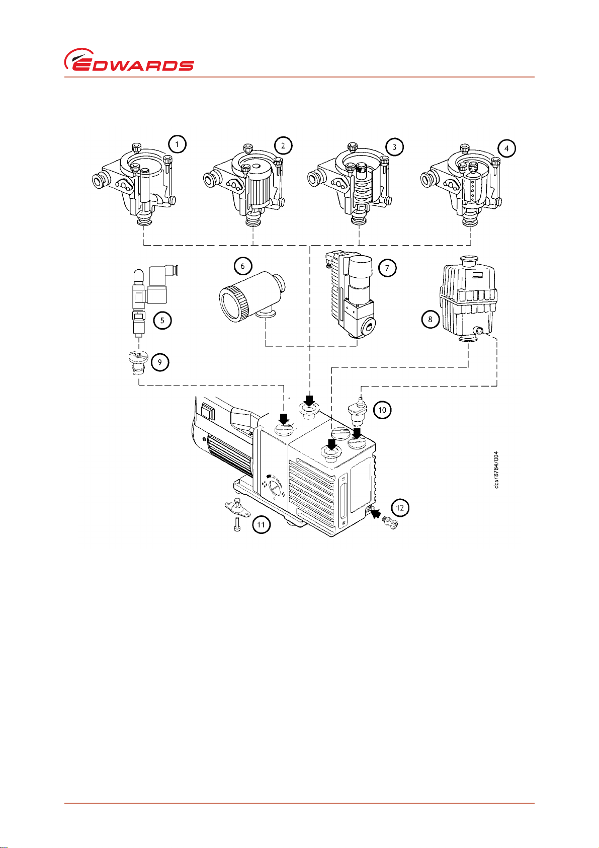
Figure 10 - Accessories
A652–01–880 Issue Y
Service and spares
1. Inlet catchpot
2. Inlet dust filter
3. Inlet desiccant trap
4. Inlet chemical trap
5. Solenoid operated gas-ballast valve
6. Foreline trap
7. Solenoid operated pipeline valve
© Edwards Limited 2018. All rights reserved. Page 45
Edwards and the Edwards logo are trade marks of Edwards Limited.
8. Outlet mist filter
9. Gas-ballast adaptor
10.Gravity oil drain kit
11.Vibration isolators
12.Oil drain-extension
Page 54

A652–01–880 Issue Y
This page has been intentionally left blank.
Page 46 © Edwards Limited 2018. All rights reserved.
Edwards and the Edwards logo are trade marks of Edwards Limited.
Page 55

A652–01–880 Issue Y
8 PFPE-prepared RV pumps
8.1 Summary
If a PFPE-prepared RV pump has been ordered, the pump will be supplied prepared for use with Edwards PFPE
mechanical pump oils, such as Fomblin YVAC 06/6 and Krytox 1506.
PFPE-prepared RV pumps are suitable for pumping high concentrations of oxygen.
Refer to Edwards publication P400–40–100 (Vacuum pump and Vacuum System Safety) before installing and using a
PFPE-prepared RV pump.
8.2 Installation
CAUTION
Never use hydrocarbon lubricants in a PFPE-prepared pump.
When filling the RV pump with oil (as described in Section 3.5), a suitable Edwards PFPE oil must be used. Do not use
a hydrocarbon oil.
PFPE-prepared RV pumps
8.3 Operation
WARNING
PFPE-prepared RV pumps are suitable for pumping high concentrations of oxygen, but Edwards
recommends that PFPE-prepared RV pumps are not used for the pumping of hazardous materials.
Operation of a PFPE-prepared RV pump is as specified in Section 4, but take note of the warning above.
8.4 Maintenance
WARNING
Obey the safety instructions given below and take note of appropriate precautions. Failure to do
so can cause injury to people.
Take additional care if it is suspected that the pump (and hence the PFPE oil) has overheated.
Do not touch or inhale the thermal breakdown products of PFPE oil which may be present if the pump has
been heated to 260°C and above. PFPE oils are safe in normal use but can decompose into very dangerous
substances if they are heated to 260°C and above. The pump may have overheated if it was misused, if it
malfunctioned, or if it was in a fire. Material Safety Data Sheets for PFPE oils used in the pump are available
on request: contact the supplier or Edwards.
Fomblin oil has different properties from other pump oils, therefore:
If the PFPE-prepared RV pump is filled with Fomblin oil, Edwards recommends regular checks for oil leaks are
carried out, particularly around the shaft seals.
If an oil leak is detected, contact the supplier or Edwards for advice.
© Edwards Limited 2018. All rights reserved. Page 47
Edwards and the Edwards logo are trade marks of Edwards Limited.
Page 56

A652–01–880 Issue Y
This page has been intentionally left blank.
Page 48 © Edwards Limited 2018. All rights reserved.
Edwards and the Edwards logo are trade marks of Edwards Limited.
 Loading...