

Page 1
Instruction Manual
iXH, iXL and pXH Dry Pumping Systems
M561-00-880
Issue C Original
Page 2
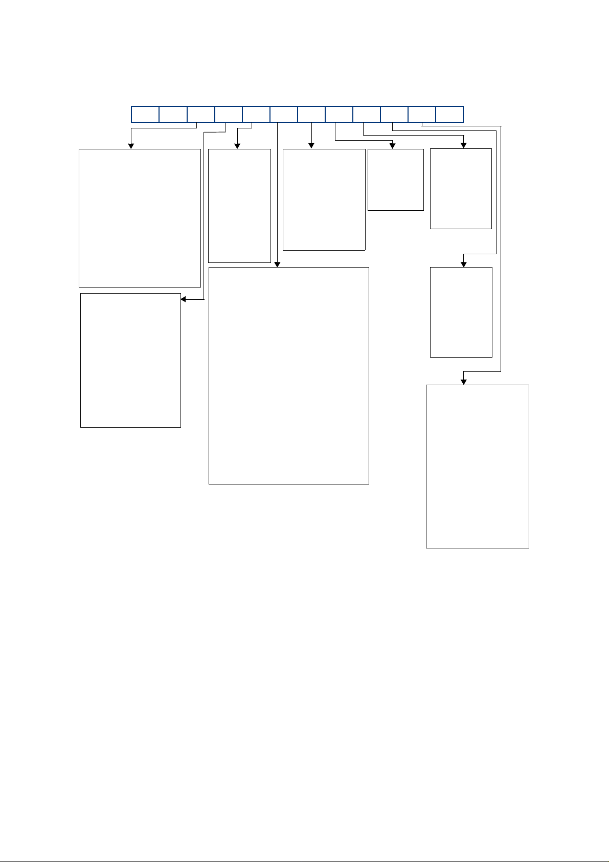
iXH and pXH Dry Pumping Systems
ACXXXXXXXXX0
Booster Size
Low Voltage
0 = None
1 = 600G
2 = r
3 = 1200
4 = 1800
5 = 3000
6 = 4500
7 = 6000
Dry Pump
Standard
0 = None (pXH)
1 = 100
2 = 200
3 = 300
4 = r
5 = r
6 = r
7 = r
TMS System
0 = Standard
1 = T-Variant
2 = T-Variant
+ heated
booster
3 = r
4 = r
5 = r
Gas Module
0 = None (pXH) 6 = Single Mode +
1 = Loadlock (44 slm flow)
(4 slm flow)
2 = Single Mode 7 = Single Mode +
(44 slm flow) (96 slm flow)
3 = Single Mode 8 = Single Mode +
(96 slm flow) (133 slm flow)
4 = Single Mode 9 = Single Mode +
(133 slm flow) (204 slm flow)
5 = Single Mode A = Multi Mode
(204 slm flow) (44 slm flow)
B = Multi Mode
(96 slm flow)
C = Multi Mode
(133 slm flow)
D = Multi Mode
(204 slm flow)
Exhaust
0 = r
1 = Standard
without
check valve.
2 = r
3 = Standard with
check valve.
Seals
0 = r
1 = r
2 =Standard
Pump
Motor
0 = None
1 = 4.5 kW
2 = 7.5 kW
3 = 11 kW
Booster
Motor
0 = None
1 = 1.9 kW
2 = 4.5 kW
3 = 7.5 kW
4 = r
High Voltage
A = None
B = 600G
C = r
D = 1200
E = 1800
F = 3000
G = 4500
H = 6000
Harsh
A = 100
B = 200
C = 300
D = 450
E = 500
Where r = reserved for future use
Special
Features
0 = None
1 = Application Specific
2 = Application Specific
3 = Application Specific
4 = Application Specific
5 = Application Specific
6 = Application Specific
7 = Application Specific
8 = Application Specific
9 = Application Specific
Page 3
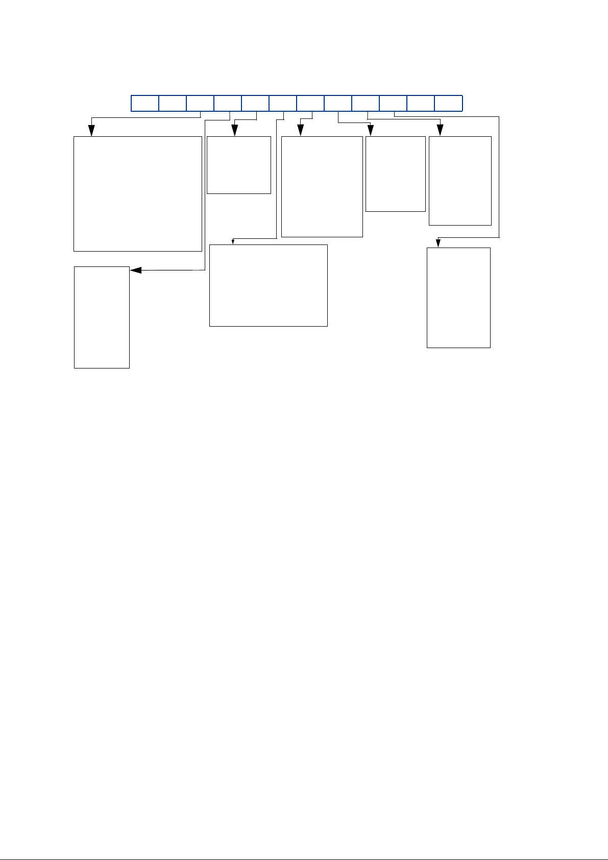
iXL Dry Pumping Systems
ASXXXXXXXX00
Where r = reserved for future use
Booster Size
Low Voltage
0 = None
1 = r
2 = r
3 = r
4 = 1800
5 = 3000
High Voltage
A = None
B = r
C = r
D = r
E = 1800
F = 3000
TMS System
0 = Standard
1 = r
Exhaust
0 = r
1 = Standard
without
check valve.
2 = r
3 = r
Seals
0 = r
1 = r
2 = Standard
3 = EES
Pump
Motor
0 = None
1 = 4.5 kW
2 = 7.5 kW
3 = 11 kW
Booster
Motor
0 = None
1 = r
2= 4.5 kW
3 = 7.5 kW
4 = r
Gas Module
0 = None
1 = Loadlock (4 slm flow)
2 = r
3 = r
4 = r
Dry Pump
0 = None
1 = r
2 = r
3 = 250
4 = r
5 = 500
6 = 750
Page 4

d
Declaration of Conformity
We, Edwards Limited,
Crawley Business Quarter,
Manor Royal,
Crawley,
West Sussex RH10 9LW, UK
declare under our sole responsibility, as manufacturer and person within the EU authorised to assemble the
technical file, that the product(s)
Low Volt Systems High Volt Systems
(200 - 230V) (380 - 460V)
iXH100 AC010xy21000 ACA10xy21000
iXH200H AC0B0xy22000 ACAB0xy22000
iXH610 AC110xy21100 ACB10xy21100
iXH1210 AC310xy21200 ACD10xy21200
iXH1210H AC3A0xy22200 ACDA0xy22200
iXH1210HT AC3A1xy22200 ACDA1xy22200
iXH1220H AC3B0xy22200 ACDB0xy22200
iXH1220HT AC3B1xy22200 ACDB1xy22200
iXH1220HTX AC3B2xy22200 ACDB2xy22200
iXH1820 AC420xy22200 ACE20xy22200
iXH1820H AC4B0xy22200 ACEB0xy22200
iXH1820T AC421xy22200 ACE21xy22200
Where x = 1, 2, 3, 4, 5, 6, 7, 8, 9, A, B, C or D depending on gas module type
Where y=1 means 'no check valve' and y=3 means 'check valve supplied'
to which this declaration relates is in conformity with the following standard(s) or other normative document(s):
EN1012-2: 1997 Compressor and Vacuum Pumps Safety Requirements; Part 2 - Vacuum Pumps.
EN61010-1: 2010 Safety Requirements for Electrical Equipment for Measurement, Control and
Laboratory Use; Part 1 – General Requirements.
EN 61326-1: 2006 Electrical equipment for measurement, control and laboratory use -
EMC requirements (Industrial Location Immunity – Class A Emissions)
EN50581:2012 Technical Documentation for the Assessment of Electrical and Electronic Products
with respect to the Restriction of Hazardous Substances
ANSI/UL 61010-1 and CAN/CSA-C22.2 No. 61010-1, 2
Safety Requirements for Electrical Equipment for Measurement, Control and Laboratory Use, Part 1: General
Requirements
SEMI S2-0709 - Environmental, Health, and Safety Guideline for Semiconductor Manufacturing Equipment
when installed in accordance with the instruction manual supplied with the pump, following the provisions of:
2006/95/EC Low Voltage Directive.
2004/108/EC Electromagnetic Compatibility Directive.
2006/42/EC Machinery Safety Directive.
2011/65/EU* Restriction of Certain Hazardous Substances (RoHS) Directive
* i.e. The product(s) contain less than - 0.1wt% for hexavalent chromium, lead, mercury, PBB and PBDE; 0.01wt%
for cadmium - in homogeneous materials (subject to the exemptions allowed by the Directive ). The RoH S
Directive does not legally apply to industrial vacuum equipment until July 2019 (July 2017 for instruments).
Note: This declaration covers all product serial numbers from the date this Declaration was signed
onwards.
22.10.2013, Burgess Hill
Mr Mark Hope, Global Technical Support Manag er Date and Place
nd
Edition July 12, 2004, including revision July 22, 2005 -
This product has been manufactured under a quality system certifie
to ISO9001:2008
P200-02-320 Issue J
Page 5

Declaration of Conformity
We, Edwards Limited,
Crawley Business Quarter
Manor Royal,
Crawley,
West Sussex RH10 9LW, UK
declare under our sole responsibility, as manufacturer and person within the EU authorised to assemble the
technical file, that the product(s)
Low Volt Systems High Volt Systems
(200-230V) (380-460V)
iXH3030 AC530xy22300 ACF30xy22300
iXH3030T AC531xy22300 ACF31xy22300
iXH3030TX AC532xy22300 ACF32xy22300
iXH3045H AC5D0xy23310 ACFD0xy23310
iXH4545HT AC6D1xy23300 ACGD1xy23300
iXH4545HT - ACGD1B123390
iXH6045H AC7D0xy23300 ACHD0xy23300
iXH6045H AC7D02123310 ACHD02123310
iXH6045HT AC7D1xy23300 ACHD1xy23300
iXH450H AC0D0xy23000 ACAD0xy23000
pXH4500 AC6000120300 ACG000120300
pXH4500 - ACG000120310
pXH6000 AC7000120300 ACH000120300
iXL500Q AS450zy23300 ASE50zy23300
Where y = 1 means 'no check valve' and y=3 means 'check valve supplied'
Where z = 1, 2, 3, 5, A or B depending on gas module type for iXL
EN 61326-1: 2006 Electrical equipment for measurement, control and laboratory use - EMC requirements
(Industrial Location Immunity – Class A Emissions)
22.10.2013, Burgess Hill
Mr Mark Hope, Global Technical Support Manager Date and Place
iXL500R AS550zy23300 ASF50zy23300
Where x = 1, 2, 3, 4, 5, 6, 7, 8, 9, A, B, C or D depending on gas module type
to which this declaration relates is in conformity with the following standard(s)
or other normative document(s)
EN1012-2: 1997 Compressor and Vacuum Pumps Safety Requirements. Part 2 - Vacuum Pumps
EN61010-1: 2010 Safety Requirements for Electrical Equipment for Measurement, Control and Laboratory
EN50581:2012 Technical Documentation for the Assessment of Electrical and Electronic Products
ANSI/UL 61010-1 and CAN/CSA-C22.2 No. 61010-1, 2
Safety Requirements for Electrical Equipment for Measurement, Control and Laboratory Use, Part 1: General
Requirements
SEMI S2-0709 - Environmental, Health, and Safety Guideline for Semiconductor Manufacturing Equipment
when installed in accordance with the instruction manual supplied with the pump,
following the provisions of:
2006/95/EC Low Voltage Directive
2004/108/EC Electromagnetic Compatibility Directive
2006/42/EC Machinery Safety Directive
2011/65/EU* Restriction of Certain Hazardous Substances (RoHS) Directive
* i.e. The product(s) contain less than - 0.1wt% for hexavalent chromium, lead, mercury, PBB and PBDE; 0.01wt% for
cadmium - in homogeneous materials (subject to the exemptions allowed by the Directive). The RoHS Directive does
not legally apply to industrial vacuum equipment until July 2019 (July 2017 for instruments).
Note: This declaration covers all product serial numbers from the date this Declaration was signed onwards.
This product has been manufactured under a quality system certified to ISO9001:2008
Use. Part 1 – General Requirements.
with respect to the Restriction of Hazardous Substances
nd
Edition July 12, 2004, including revision July 22, 2005 -
P200-02-720 Issue K
Page 6

Declaration of Conformity
We, Edwards Limited,
Crawley Business Quarter,
Manor Royal,
Crawley,
West Sussex, RH10 9LW, UK
declare under our sole responsibility, as manufacturer and person within the EU authorised to assemble the
technical file, that the product(s)
Low Volt Systems High Volt Systems
(200-230V) (380-460V)
iXH500H AC0E0xy23000 ACAE0xy23000
iXH3050H AC5E0xy23310 ACFE0xy23310
iXH3050HTX AC5E2xy23300 ACFE2xy23300
iXH4550HT AC6E1xy23300 ACGE1xy23300
iXH6050H AC7E0xy23300 ACHE0xy23300
iXH6050HT AC7E1xy23300 ACHE1xy23300
Where x = 1, 2, 3, 4, 5, 6, 7, 8, 9, A, B, C or D depending on gas module type
to which this declaration relates is in conformity with the following standard(s) or other normative document(s)
EN1012-2:1996, A1: 2009 Compressors and Vacuum Pumps. Safety Requirements.
Part 2 - Vacuum Pumps.
EN61010-1: 2010 Safety Requirements for Electrical Equipment for Measurement,
EN 61326-1: 2006 Electrical equipment for measurement, control and laboratory
EN50581:2012 Technical Documentation for the Assessment of Electrical and Electronic Products
ANSI/UL 61010-1 and CAN/CSA-C22.2 No. 61010-1, 2nd Edition July 12, 2004, including revision July 22, 2005 – Safety
Requirements for Electrical Equipment for Measurement, Control and Laboratory Use - Part 1: General Requirements
and fulfils all the relevant provisions of
2006/42/EC Machinery Directive
2006/95/EC Low Voltage Directive
2004/108/EC Electromagnetic Compatibility (EMC) Directive
2011/65/EU* Restriction of Certain Hazardous Substances (RoHS) Directive
* i.e. The product(s) contain less than - 0.1wt% for hexavalent chromium, lead, mercury, PBB and PBDE; 0.01wt% for
cadmium - in homogeneous materials (subject to the exemptions allowed by the Directive). The RoHS Directive does
not legally apply to industrial vacuum equipment until July 2019 (July 2017 for instruments).
Note: This declaration covers all product serial numbers from the date this Declaration was signed onwards.
22.10.2013, Burgess Hill
Where y = 1 means ‘no check valve’ and y = 3 means ‘check valve supplied’
Control and Laboratory Use. Part 1 - General Requirements.
Use - EMC requirements. (Industrial Location Immunity
- Class A Emissions)
with respect to the Restriction of Hazardous Substances
Mr Mark Hope, Global Technical Support Manager Date and Place
This product has been manufactured under a quality system certified to ISO9001:2008
P200-06-000 Issue C
Page 7

Declaration of Conformity
We, Edwards Limited,
Crawley Business Quarter,
Manor Royal,
Crawley,
West Sussex RH10 9LW, UK
declare under our sole responsibility, as manufacturer and person within the EU authorised to assemble the
technical file, that the product(s)
Low Volt Systems High Volt Systems
(200-230V) (380-460V)
iXL250Q AS43001x2300 ASE3001x2300
iXL750Q AS46001x4300 ASE6001x4300
Where x = 2 means 'standard booster oilbox evacuation' and x=3 means 'external booster oilbox evacuation'
EN 61326-1: 2006 Electrical equipment for measurement, control and laboratory use - EMC requirements
(Industrial Location Immunity – Class A Emissions)
iXL750R AS56001x4300 ASF6001x4300
to which this declaration relates is in conformity with the following standard(s) or other normative document(s)
EN1012-2: 1997 Compressor and Vacuum Pumps Safety Requirements. Part 2 - Vacuum Pumps
EN61010-1: 2010 Safety Requirements for Electrical Equipment for Measurement, Control and Laboratory
ANSI/UL 61010-1 and CAN/CSA-C22.2 No. 61010-1, 2
Safety Requirements for Electrical Equipment for Measurement, Control and Laboratory Use, Part 1: General
Requirements
when installed in accordance with the instruction manual supplied with the pump,
following the provisions of:
2006/95/EC Low Voltage Directive
2004/108/EC Electromagnetic Compatibility Directive
2006/42/EC Machinery Safety Directive
Note: This declaration covers all product serial numbers from the date this Declaration was signed onwards.
Mr Mark Hope, Global Technical Support Manager Date and Place
This product has been manufactured under a quality system certified to ISO9001:2008
Use. Part 1 – General Requirements.
nd
Edition July 12, 2004, including revision July 22, 2005 -
22.10.2013, Burgess Hill
P200-06-620 Issue B
Page 8
P601-01-100
2020
NWNW
Issue C Original
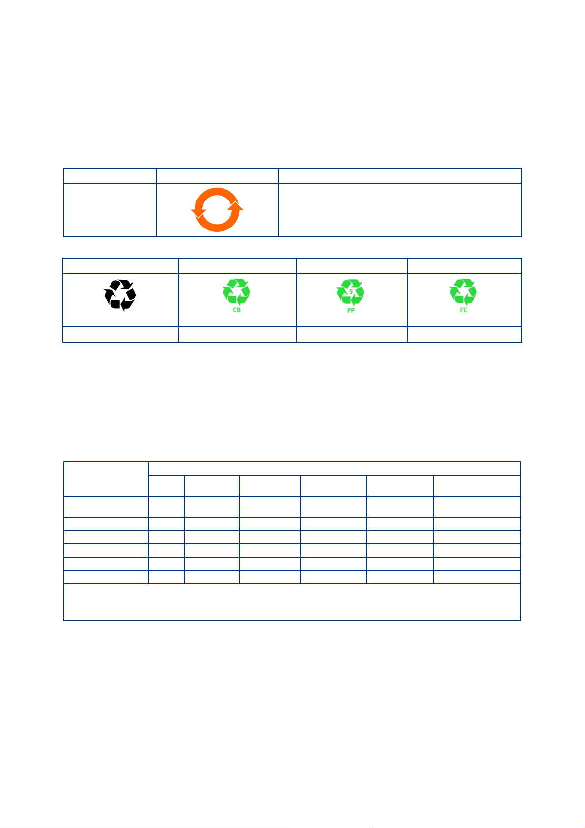
The Chinese regulatory requirement on the Control of Pollution Caused by Electronic Information Products No. 39
(also known as ‘China RoHS’) mandates that manufacturers of certain categories of electronic products sold in Ch ina
after 1st March 2007 –
Mark the product and packaging
Define the Product’ s Environment Protection Use Period (EPUP)
Provide a Materials Content Declaration.
Product Labels
Product Product Label Meaning
All iXH, iXL500 and
pXH models
Indicates toxic or hazardous substance contained in at least
one of the homogeneous materials used for this part is
above the limit requirement in SJ/T11363-2006.
Environmental Protection Use Period is 20 years.
Packaging information
Pallet Overshipper Protection Pieces Support Braces
Recyclable Natural Wood Recyclable Cardboard Recyclable Polypropylene Recyclable Mild Steel
Environment Protection Use Period (EPUP)
This is the period in years during which the toxic or hazardous substances or elements contained in this product will
not leak or mutate under normal operating conditions so that the use of such electronic information products will
not result in any severe environmental pollution, any bodily injury or damage to any assets.
The Environmental Protection Use Period is 20 years for this product.
For the purposes of EPUP, normal operating conditions are considered to be use in accordance with the product’s
instruction manual.
Materials Content Declaration for all iXH, iXL & pXH models
Toxic or Hazardous Substances and Elements
Part name
Motor (Mechanical
Booster)
Motor (pump) O O O O O O
Pump & Booster O O O O O O
Electronics and Controls O O X O O O
Cooling System O O O O O O
Purge System O O O O O O
O: Indicates that this toxic or hazardous substance contained in all of the homogeneous materials for this part is below the limit requirement in
SJ/T11363-2006.
X: Indicates that this toxic or hazardous substance contained in at least one of the homogeneous materials used for this part is above the limit
requirement in SJ/T11363-2006.
Lead (Pb) Mercury (Hg) Cadmium (Cd)
OO O O O O
Hexavalent
Chromium (Cr (VI))
Poly brominated
biphenyls (PBB)
Poly bromi nat ed
diphenyl ethers (PBDE)
DJD 24/03/10
Page 9

M561-00-880 Issue C
Contents
Section Page
1 Introduction .......................................................................................1
1.1 Scope and definitions ................................................................................................... 1
1.2 Applications ............................................................................................................... 2
1.3 Description ................................................................................................................ 2
1.4 Priority of control ........................................................................................................ 2
1.5 Active utility control .................................................................................................... 3
2 Technical data ....................................................................................5
2.1 General technical data .................................................................................................. 5
2.2 Performance data ........................................................................................................ 7
2.3 Loading data .............................................................................................................. 8
2.4 Nitrogen purge data ..................................................................................................... 9
2.5 Electrical data ...........................................................................................................11
2.6 Cooling-water data .....................................................................................................17
2.7 T variants ................................................................................................................20
2.8 T rac er gas analysis .....................................................................................................20
Contents
3 Installation .................................................... ................................... 23
3.1 Locate the dry pumping system ......................................................................................24
3.2 Lubric ation ............................................................................................................... 25
3.3 Connect the dry pumping system to your vacuum/exhaust system .............................................25
3.4 Connect to your factory extraction system (optional) ............................................................27
3.5 Connect the nitrogen supply ..........................................................................................28
3.5.1 Flammable/pyrophoric materials ....................................................................................28
3.5.2 Gas purges ...............................................................................................................29
3.6 Leak-test the system ...................................................................................................29
3.7 Electrical supply ........................................................................................................29
3.7.1 Mains supply cable connection .......................................................................................31
3.8 Connect an additional RF earth (ground) (optional) ..............................................................35
3.9 Connect to your emergency stop circuit ............................................................................35
3.10 Connect and set up the cooling-water ..............................................................................36
3.11 Accessories ............................................................................................................... 37
3.12 Commission the system ................................................................................................37
3.13 Install additional safety equipment ..................................................................................38
4 Operation ........................................................................................ 39
4.1 Start-up ..................................................................................................................39
4.1.1 MicroTIM operation .....................................................................................................40
4.1.2 PDT operation ...........................................................................................................40
4.1.3 Front panel control operation ........................................................................................40
4.2 Status indicators ........................................................................................................40
4.3 Manual shut-down ......................................................................................................41
4.3.1 Shut-down modes .......................................................................................................41
4.3.2 MicroTIM operation .....................................................................................................41
4.3.3 PDT operation ...........................................................................................................41
4.3.4 Front panel control operation ........................................................................................41
4.4 Automatic shut-down ..................................................................................................42
4.5 Unplanned shut-down and alarms ....................................................................................43
4.6 Emergency stop .........................................................................................................44
4.7 Restart the pump after an emergency stop or automatic shut-down ..........................................44
4.8 Advanced control and monitoring ....................................................................................44
gea/0179/01/12
© Edwards Limited 2012. All rights reserved. Page i
Edwards and the Edwards logo are trademarks of Edwards Limited.
Page 10

M561-00-880 Issue C
Contents
5 Maintenance ..................................................................................... 45
5.1 Safety and maintenance frequency ..................................................................................45
5.2 Relocate the system for maintenance ...............................................................................46
5.3 Draining the cooling water ............................................................................................47
5.4 General maintenance ..................................................................................................48
5.5 Inspect the connections, pipelines, cables and fittings ..........................................................48
5.6 Gas module configuration .............................................................................................49
5.6.1 iXH single mode and single mode+ ...................................................................................49
5.6.2 Multi mode ...............................................................................................................49
5.6.3 iXL variants ..............................................................................................................50
5.7 System operating temperature configuration ......................................................................50
6 Transportation, storage and disposal ........................................................ 51
6.1 Transportation ..........................................................................................................51
6.2 Storage ...................................................................................................................51
6.3 Disposal ...................................................................................................................51
7 Service, spares and accessories .............................................................. 53
7.1 Introduction .............................................................................................................53
7.2 S ervice ....................................................................................................................53
7.3 Ordering accessories ...................................................................................................54
Appendix A1 Pump display terminal .................................................................. 57
A1.1 LEDs .......................................................................................................................57
A1.2 Pump start / stop and control ........................................................................................57
A1.3 Warning / Alarm display and acknowledgement ...................................................................58
A1.4 Menus ..................................................................................................................... 58
A1.4.1 Normal menu ............................................................................................................58
A1.4.2 Status menu .............................................................................................................59
A1.4.3 SETUP menu .............................................................................................................60
A1.4.4 COMMANDS menu .......................................................................................................61
A1.4.5 INV FAULT HIST (Display Inverter Fault History) menu ...........................................................61
A1.4.6 SOFTWARE VERSION Display menu ...................................................................................62
A1.4.7 FIT ACCESSORY menu ..................................................................................................62
A1.4.8 IP Configuration menu .................................................................................................62
A1.4.9 Display attributes menu ...............................................................................................63
Appendix A2 Troubleshooting .......................................................................... 65
A2.1 Warnings .................................................................................................................65
A2.1.1 LED warning indicators ................................................................................................. 65
A2.1.2 PDT warnings ............................................................................................................65
A2.2 Alarms ....................................................................................................................68
A2.2.1 LED alarm indicators ...................................................................................................68
A2.2.2 PDT alarms ...............................................................................................................68
A2.3 Inverter warnings and alarms .........................................................................................70
A2.4 Other problems .........................................................................................................75
A2.4.1 Pump controller communications ....................................................................................75
For return of equipment, complete the HS Forms at the end of this manual.
Page ii © Edwards Limited 2012. All ri ghts reserved.
Edwards and the Edwards logo are trademarks of Edwards Limited.
Page 11

M561-00-880 Issue C
Illustrations
Figure Page
1 Applications ............................................................................................................... 2
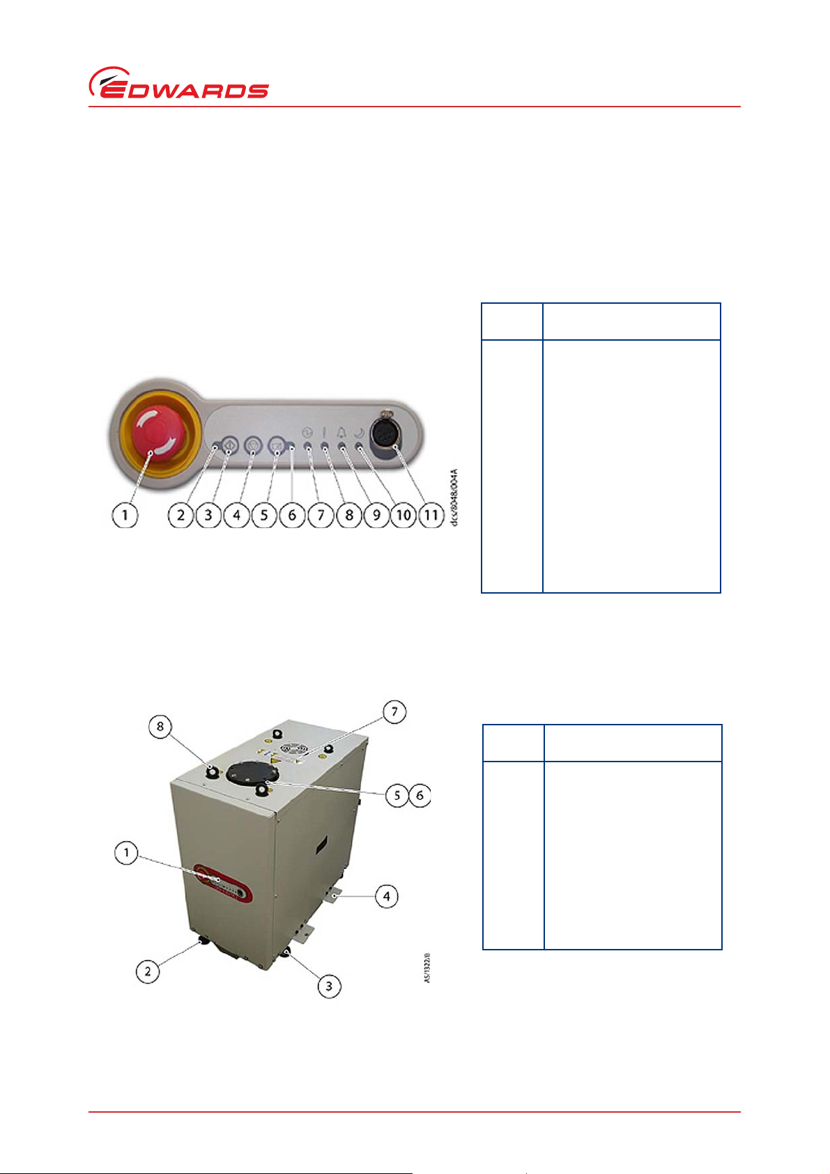
2 The front panel controls ................................................................................................ 3
3 Front view of pumping system ......................................................................................... 3
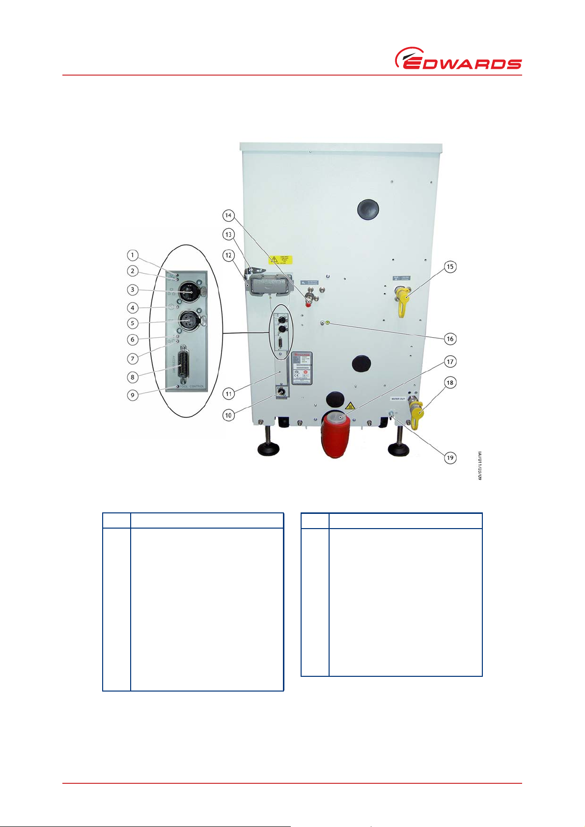
4 The controls/connectors on the rear of the pump ................................................................. 4
5 Centre of gravity and levelling foot loads ........................................................................... 9
6 Reduce the effective system footprint ..............................................................................25
7 Connecting the pump inlet ............................................................................................27
8 The Harting Han
9 The Harting 100A axial screw module cable-mounted connector ...............................................33
10 Customer connection kit - combination low volts iXL750 ........................................................34
11 Electrical connector locking mechanism ............................................................................35
A1 Pump display terminal .................................................................................................57
®
K 4/4 cable-mounted connector ...............................................................32
Tables
Contents
Table Page
1 General technical data .................................................................................................. 5
2 General technical data .................................................................................................. 6
3 Performance data ........................................................................................................ 7
4 Loading data (refer to Figure 5) ....................................................................................... 8
5 Nitrogen purge data for iXH and iXL systems ........................................................................ 9
6 Gas module types and flows ..........................................................................................10
7 Electrical data iXH100 to iXH1820/H/T .............................................................................11
8 General electrical data ................................................................................................14
9 Electrical connections ..................................................................................................15
10 Wire assembly according to VDE 0295 ...............................................................................16
11 Water cooling system data ............................................................................................17
12 Cooling water supply temperature ...................................................................................18
13 Water consumption data ...............................................................................................19
14 Heater data ..............................................................................................................20
15 Tracer gas test parameters ...........................................................................................20
16 Tracer gas test system parameters ..................................................................................20
17 Worst case test results .................................................................................................21
18 Extraction rates required by system variant .......................................................................22
19 Alarm actions ............................................................................................................42
20 Pump protection sensors ..............................................................................................43
21 Dry pump and booster temperature settings .......................................................................50
22 Accessories ...............................................................................................................54
23 Seismic bracket kits ....................................................................................................55
24 Exhaust check valve kits ...............................................................................................55
A1 Pump start control ......................................................................................................57
A2 Pump stop and control .................................................................................................58
A3 Normal menu ............................................................................................................58
A4 Normal menu ............................................................................................................59
A5 Status menu .............................................................................................................59
A6 SETUP menu .............................................................................................................60
A7 COMMANDS menu .......................................................................................................61
A8 GAS VALVES menu ......................................................................................................61
A9 INV FAULT HIST (Display Inverter Fault History) menu ...........................................................61
A10 FIT ACCESSORY menu ..................................................................................................62
© Edwards Limited 2012. All rights reserved. Page iii
Edwards and the Edwards logo are trademarks of Edwards Limited.
Page 12

M561-00-880 Issue C
Contents
A11 IP Configuration menu .................................................................................................62
A12 Display attributes menu ...............................................................................................63
A13 SELECT LINE (Normal display selection menu) .....................................................................63
A14 UNITS (Units to display) ................................................................................................63
A15 Warnings .................................................................................................................65
A16 Alarms ....................................................................................................................68
A17 Hexadecimal to digital conversion ...................................................................................70
A18 Inverter alarm codes ...................................................................................................71
A19 Inverter warnings codes ...............................................................................................72
A20 Inverter diagnostic display text ......................................................................................73
Associated publications
Publication title Publication number
Vacuum Pump and Vacuum System Safety P400-40-100
Semiconductor Pumping Application Guide P411-00-090
Trademark Credits
Han® is a registered trademark of Harting Electric GmbH
EtherCon® is a registered trademark of Neutrik® AG
Fomblin® is a registered trademark of Solvay Solexis SpA
Page iv © Edwards Limited 2012 . All rights reserved.
Edwards and the Edwards logo are trademarks of Edwards Limited.
Page 13
M561-00-880 Issue C
CAUTION
WARNING
1Introduction
1.1 Scope and definitions
This manual provides installation, operation and maintenance instructions for the Edwards iXH, iXL and pXH dry
pumping systems. You must use your pumping system as speci fied i n th is man ual otherw is e the protecti on provided
by the equipment may be impaired.
Read this manual before you install and operate your pump. Important safety information is highlighted as WARNING
and CAUTION instructions; you must obey these instructions. The use of WARNINGS and CAUTIONS is defined below.
Warnings are given where failure to observe the instruction could result in injury or death to
people.
Cautions are given where failure to observe the instruction could result in damage to the equipment, associated
equipment and/or process.
Introduction
The units throughout this manual conform to the SI international system of units of measurement.
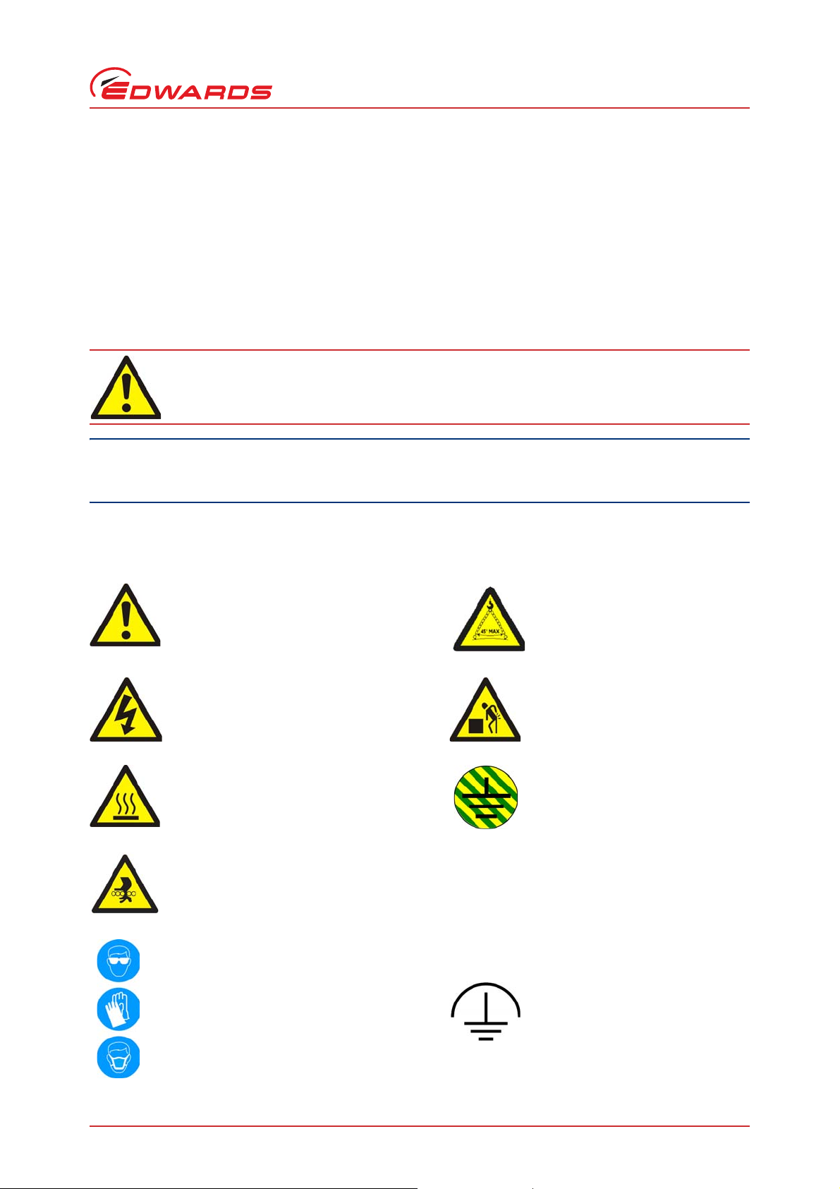
The following warning labels are on the pump:
Warning - Refer to accompanying documentation.
Warning - Risk of electric shock. Warning - Heavy object.
Warning - Hot surfaces. Protective earth (ground).
Warning - Moving parts present.
Warning - Maximum angle between
paired slings
Warning - use protective equipment. RF earth (ground).
© Edwards Limited 2012. All rights reserved. Page 1
Edwards and the Edwards logo are trademarks of Edwards Limited.
Page 14

M561-00-880 Issue C
Introduction
The following warnings only appear in this manual:
Warning - Risk of explosion. Warning - pressurised.
Material Safety Data Sheets for chemicals supplied by Edwards can be obtained by contacting Edwards, or on
www.edwardsvacuum.com.
1.2 Applications
iXH, iXL and pXH pumping systems are intended for use on the Semiconductor, Solar and FPD processes shown in
Figure 1.
Figure 1 - Applications
iXH, iXL and pXH applications
ALD Metal Etch RTP
HDP-CVD Metrology SACVD
Implant Source Oxide etch Silicon Etch
Lithography PECVD Strip/Ashing
Load lock PVD Pre-Clean Transfer
LPCVD PVD Process
MOCVD RTA
The iXL systems are intended for use on clean duty applications.
If you use the system on an application for which it is not suitable, you may invalidate your warranties. If in doubt,
contact Edwards who will advise you as to the suitability of the system for any particular application.
1.3 Description
The iXH dry pump range has been developed to m ee t the demanding requirements for process pumping solutions in
the Semiconductor, Flat Panel and Solar industries. The range se ts new standards for harsh process capability,
reliability and reduced cost of ownership in lo w footprint packages.
The iXL pump range has been developed to meet cyclic loadlock duty applications used in the flat panel and solar
industries.
The pXH booster systems are not intended for use as stand-alone units. Each system must be backed using a suitable
Edwards dry pump selected to match process and performance specifications.
1.4 Priority of control
The pumping system can be controlled by a number of modules: the front control panel (refer to Figure 2), a Pump
Display Terminal (PDT), the Edwards System Controller or by the tool through the MicroTIM or one of the serial
interfaces. Only one of these can have control of the system at any one time. That is, once one of these has control
of the system, control requests from the others are denied.
In addition to the control modules listed above, the pXH proximity booster can control or be controlled by the
Edwards backing pump. C ontact Edwards for more information on how to control a pXH using an iXH or other Edwards
pumping system.
The PDT indicates who is in control. LEDs are also provided on the rear pane l, front panel or PDT, which illuminate
to indicate 'in control'.
Page 2 © Edwards Limited 2012. All rights reserved.
Edwards and the Edwards logo are trademarks of Edwards Limited.
Page 15
M561-00-880 Issue C
Item
Control/connector
identification
1EMS button
2 Running LED (green)
3 Start button
4Stop button
5 Local control button
6 Local control LED (green)
7 Power LED (green)
8 Warning LED (amber)
9Alarm LED (red)
10 Green Mode LED (green)
11 PDT (Pump Display Terminal)
connection
Item
Control/connector
identification
1 Front panel control
2 Levelling feet (4 off)
3Castors (4 off)
4 Seismic bracket (4 off if
fitted)
5 Pumped gas inlet connection
6 RF Earth (ground) cable
7Extraction port
8 Lifting eyebolts (4 off)
1.5 Active utility control
The Active Utility Control (Green Mode) function reduces utility consumption of the system while on stand-by. The
Green Mode functionality is controlled by the on/off process signal from the Tool Interface Module. Contact Edwards
for advice on application and activation.
Figure 2 - The front panel controls
Introduction
Figure 3 - Front view of pumping system
Note: iXH 100, iXH 200H and iXH 610 variants have only two eyebolts provided for lifting.
© Edwards Limited 2012. All rights reserved. Page 3
Edwards and the Edwards logo are trademarks of Edwards Limited.
Page 16
M561-00-880 Issue C
Item Control/connector identification
1 Ethernet LAN LED (green)
2 Ethernet link LED (yellow)
3 Ethernet connection
4Power LED (green)
5System interface
6 Warning LED (yellow)
7 Running and Alarm LEDs (2 colours,
either green or red)
8 Accessory interface
9 MicroTIM in control LED (green)
10 EMS interface
11 Micro TIM connection (if fitted)
12 Electrical supply connection
13 Electrical connector locking
mechanism
14 Nitrogen purge connection
15 Cooling water supply connection
16 Protective earth (ground) stud
17 Exhaust gas outlet connection
18 Cooling water return connection
19 RF earth (ground) stud
Item Control/connector identification
Introduction
Figure 4 - The controls/connectors on the rear of the pump
Page 4 © Edwards Limited 2012. All rights reserved.
Edwards and the Edwards logo are trademarks of Edwards Limited.
Page 17

© Edwards Limited 2012. All rights re served. Page 5
Edwards and the Edwards logo are trademarks of Ed wards Limited.
2Technical data
2.1 General technical data
Table 1 - General technical data
Characteristics
Body dimensions
Pump
Units mm kg dB(A) mm/s kg force kg force mm
iXH100 784 x 390 x 526 260 < 70 < 1.5 < 20 < 4 ISO63 NW40 105
iXH200H 901 x 390 x 526 287 < 70 < 1.5 < 20 < 4 ISO63 NW40 105
iXH450H 1000 x 517 x 650 455 < 70 < 1.5 < 20 < 10 ISO63 NW40 105
iXH500H 1000 x 517 x 650 490 < 70 < 1.5 < 20 < 10 ISO63 NW40 105
iXH610 784 x 390 x 780 355 < 70 < 1.5 < 20 < 4 ISO100 NW40 105
iXH1210/H 784 x 390 x 780 413 - 430 < 70 < 1.5 < 20 < 4 ISO100 NW40 105
iXH1220H/T 901 x 390 x 780 455 - 460 < 70 < 1.5 < 20 < 4 ISO100 NW40 105
iXH1820/H/T 901 x 390 x 780 471 - 487 < 70 < 1.5 < 20 < 4 ISO160 NW40 105
iXH3030/T 915 x 517 x 966 619 - 624 < 70 < 1.5 < 20 < 10 ISO160 NW40 105
iXH3045H 1000 x 517 x 966 776 70 < 1.5 < 20 < 10 ISO160 NW40 105
iXH3050H 1000 x 517 x 966 811 70 < 1.5 < 20 < 10 ISO160 NW40 105
iXH4545HT 1000 x 517 x 966 814 70 < 1.5 < 20 < 10 ISO200 NW40 105
iXH4550HT 1000 x 517 x 966 849 70 < 1.5 < 20 < 10 ISO200 NW40 105
iXH6045H/T 1080 x 517 x 966 860 - 865 74 < 1.5 < 20 < 10 ISO250 NW40 105
iXH6050H/T 1080 x 517 x 966 899 70 < 1.5 < 20 < 10 ISO250 NW40 105
pXH4500 1086 x 517 x 531 400 < 70 < 1.5 < 20 < 10 ISO200 ISO160 -
pXH6000 1086 x 517 x 531 435 < 70 < 1.5 < 20 < 10 ISO250 ISO160 -
iXL250Q 1092 x 390 x 830 515 <64 <1.5 <20 <10 ISO160 NW40 105
iXL500Q 1186 x 517 x 966 860 < 70 < 1.5 < 20 < 10 ISO160 NW50 105
iXL500R 1186 x 517 x 966 874 < 70 < 1.5 < 20 < 10 ISO160 NW50 105
Length x Width x
Height
(excludes exhaust
enclosure)
*
Mass
(excluding
packaging)
Noise level
(at ultimate)
Typical
vibration
level at inlet
Initial force
to push the
pump
†
Sustained
force to push
the pump
†
Pump inlet
flange
(bolted)
Exhaust gas
outlet
Extraction
diameter
port
M561-00-880 Issue C
Technical data
Page 18

Technical data
Page 6 © Edwards Limited 2012. All rights reserved.
Body dimensions
Pump
Units mm kg dB(A) mm/s kg force kg force mm
iXL750Q 1622 x 517 x 1031 918 <70 <1.5 22 <10 ISO160 NW50 105
iXL750R 1622 x 517 x 1031 976 <70 <1.5 22 <10 ISO160 NW50 105
*
Contact Edwards for installation drawings
†
Measured in laboratory on level concrete surface
Edwards and the Edwards logo are trademarks of Edwards Limited.
Item Description Rating Units
Operating conditions
Materials in contact with process gas
Degree of protection provided by
enclosure
Length x Width x
Height
(excludes exhaust
enclosure)
*
Mass
(excluding
packaging)
Intended use Indoor
Ambient temperature range:
Operating 5 to 40 °C
Storage -45 to 55 °C
Maximum relative humidity: 80% for temperatures up to 31 °C decreasing linearly to 50% relative
Maximum operating altitude 2000 m
Pollution degree 2 (IEC 61010)
Pump, shaft and rotors Ca st Iron, Steel
Seals PTFE and fluoroelastomer
Gas system Stainless steel, aluminium, brass, PTFE and fluoroelastomer
Enclosure protection when installed IP21D (IEC60529)
Table 1 - General technical data (continued)
Characteristics
Noise level
(at ultimate)
Table 2 - General technical data
Typical
vibration
level at inlet
humidity at 40 °C
Initial force
to push the
pump
†
Sustained
force to push
the pump
†
Pump inlet
flange
(bolted)
Exhaust gas
outlet
Extraction
port
diameter
M561-00-880 Issue C
Page 19

© Edwards Limited 2012. All rights re served. Page 7
Edwards and the Edwards logo are trademarks of Ed wards Limited.
2.2 Performance data
Table 3 - Performance data
Characteristics
Pump
Units m
Typical peak pumping speed
3
/h mbar mbar
iXH100 100 < 3 x 10
iXH200H 215 < 3 x 10
iXH450H 500 < 3 x 10
iXH500H 500 < 3 x 10
iXH610 665 < 5 x 10
iXH1210/H 1025 - 1065 < 5 x 10
iXH1220H/T 1200 - 1250 < 5 x 10
iXH1820/H/T 1700 - 1900 < 5 x 10
iXH3030/T 2750 - 2900 < 5 x 10
iXH3045H 3225 < 5 x 10
iXH3050H 3200 < 5 x 10
iXH4545HT 4450 < 5 x 10
iXH4550HT 4220 < 5 x 10
iXH6045H/T 5000 - 5200 < 5 x 10
iXH6050H/T 5000 - 5200 < 5 x 10
pXH4500 N/A < 5 x 10
pXH6000 N/A < 5 x 10
iXL250Q 1900 < 1 x 10
iXL500Q 2150 < 5 x 10
iXL500R 3100 < 5 x 10
iXL750Q 2300 < 1 x 10
iXL750R 3450 < 1 x 10
*
Speed may be limited
†
Ultimate achieved when pXH used in conjunction with an appropriate backing pump. Please contact Edwards to discuss your application. The pXH does not
have a shaft seal purge.
Ultimate
(shaft seal purge only)
-2
-2
-2
-2
-3
-3
-3
-3
-3
-3
-3
-3
-3
-3
-3
-3†
-3†
-3
-3
-3
-3
-3
Maximum continuous inlet pressure
1000
1000
*
1000
*
1000
1000
1000
1000
1000
*
1000
*
1000
*
1000
*
1000
*
1000
*
1000
*
1000
*
1000
*
1000
*
1000
*
1000
*
1000
*
1000
*
1000
M561-00-880 Issue C
Technical data
Page 20
Technical data
Page 8 © Edwards Limited 2012. All rights reserved.
M561-00-880 Issue C
2.3 Loading data
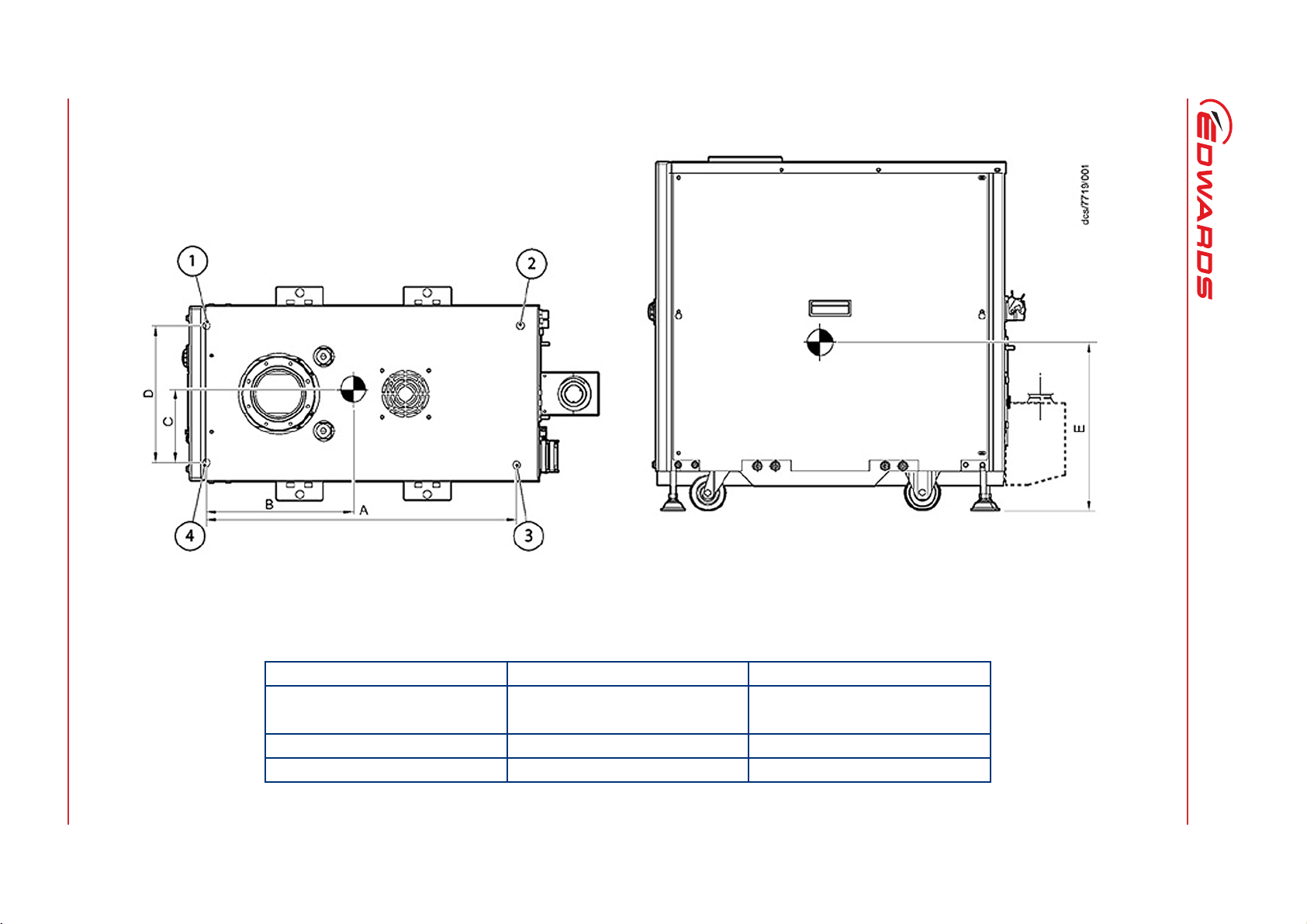
Table 4 - Loading data (refer to Figure 5)
Pump
Unitsmmmmmmmmmm kg kg kg kg
iXH100 697 295 165.5 311 280 80 59 51 70
iXH200H 814 403 165.5 311 261 77 76 66 68
iXH450H 924 443 220 427 323 122 112 106 115
iXH500H 924 422 220 427 324 137 115 109 129
iXH610 697 329 165.5 311 374 100 89 78 88
iXH1210/H 697 330 165.5 311 430 122 106 94 108
Edwards and the Edwards logo are trademarks of Edwards Limited.
iXH1220H/T 814 457 165.5 311 430 107 136 120 94
iXH1820/H/T 814 400 165.5 311 433 134 127 112 118
iXH3030/T 829 395 230 436 545 183 147 131 164
iXH3045H 924 422 220.5 427 534 218 183 171 203
iXH3050H 924 409 220 427 524 233 185 174 219
iXH4545HT 924 422 220.5 427 539 228 192 180 214
iXH4550HT 924 411 220.5 427 529 243 195 183 228
iXH6045H/T 1004 398 220.5 427 549 269 177 166 252
iXH6050H/T 1004 388 220.5 427 539 285 179 168 267
pXH4500 990 460.5 225 438 325 110 96 90 104
pXH6000 990 422 224.5 438 326 128 95 90 122
iXL250Q 1038 421 130.5 261 463 154 103 103 154
iXL500Q 1110 497 219 427 468 212 172 164 202
iXL500R 1110 497 219 427 468 241 195 185 229
iXL750Q 1547 730.9 169 338 512.2 215 244 244 215
iXL750R 1547 722.1 169 338 534.6 229 259 259 229
ABCDE1234
Dimension to centre of gravity Load at levelling foot position
Page 21
© Edwards Limited 2012. All rights re served. Page 9
Edwards and the Edwards logo are trademarks of Ed wards Limited.
Figure 5 - Centre of gravity and levelling foot loads
2.4 Nitrogen purge data
Table 5 - Nitrogen purge data for iXH and iXL systems
Characteristics Rating Units
Nitrogen supply pressure range 2.5-6.9 bar gauge
Nitrogen supply quality To ISO 8573
Nitrogen inlet connection 1/4 inch tube fitting
Note: pXH systems do not have a nitrogen purge facility.
M561-00-880 Issue C
36 - 100 psi gauge
Technical data
Page 22

Technical data
Page 10 © Edwards Limited 2012. All rights reserved.
Edwards and the Edwards logo are trademarks of Edwards Limited.
Note: If you are not sure which gas module is fitted to your system, find the product code number on the label on the rear of the pump and then refer to the
product configurators at the start of this manual.
Table 6 - Gas module types and flows
For iXH systems:
Gas module
type
Loadlock Shaft seal only 4 4 - - - - -
Single mode
Single mode +
Multi mode
*
Contact Edwards
Note: H variant pumps fitted with Single Mode+ modules include the innovative Gas Buster
Description
Gas ballast purge with harsh/medium
manually selected
Gas ballast purge with harsh/medium
manually selected + inlet purge
Gas ballast purge with electronically selected
harsh/medium + inlet purge + exhaust purge
Module
sizes
available
44 44 28 - - - slm
96 96 56 - - - slm
133 133 88 - - - slm
204 204 133 - - - slm
44 44 28 60 - - slm
96 96 56 122 - - slm
133 133 88 173 - - slm
204 204 133 264 - - slm
44 44 22 60 94 110 slm
96 96 34 122 146 172 slm
133 133 65 173 183 223 slm
204 204
Total fl ow,
harsh
setting
Total flow,
medium
setting
*
TM
inlet purge for improved powder handling.
Total flow
with inlet
purge
264 254 314 slm
Total fl ow
with
exhaust
purge
Total flow
with inlet
and exhaust
purge
Units
M561-00-880 Issue C
For iXL systems:
iXL systems are designed for use on clean applications only.
Page 23

© Edwards Limited 2012. All rights reserved. Page 11
Edwards and the Edwards logo are trademarks of Ed wards Limited.
2.5 Electrical data
Table 7 - Electrical data iXH100 to iXH1820/H/T
Characteristics iXH100 iXH200H iXH450H iXH500H iXH610 iXH1210 iXH1210H iXH1220H/T iXH1820/H/T Units
Dry pump motor rating 4.5 7.5 11 11 4.5 4.5 7.5 7.5 7.5 kW
Mechanical booster
motor rating
Current rating
(200 - 230 V systems)
Current rating
(380 - 460 V systems)
Recommended branch
circuit fuse UL
(200 - 230 V systems)
Recommended branch
circuit fuse IEC
(200 - 230 V systems)
Recommended branch
circuit fuse UL
(380 - 460 V systems)
Recommended branch
circuit fuse IEC
(380 - 460 V systems)
Min cable size for 200 230 V systems (or
corresponding AWG
size)
Min cable size for 380 460 V systems (or
corresponding AWG
size)
Mains connector Han
----1.94.54.54.54.5kW
21 38 44 44 28 28 38 38 38 A
11 20 23 23 14 14 20 20 20 A
25 45 55 55 35 35 45 45 45 A
25 40 45 45 30 30 40 40 40 A
15 25 30 30 20 20 25 25 25 A
15 20 25 25 15 15 20 20 20 A
*
6 (8)
*
6 (8)
®
K 4/4 Han® K 4/4 Han® K 4/4 Han® K 4/4 Han® K 4/4 Han® K 4/4 Han® K 4/4 Han® K 4/4 Han® K 4/4 -
10 (6) 10 (6) 10 (6) 6 (8)
6 (8)
*
6 (8)
*
6 (8)
*
6 (8)
*
*
6 (8)
6 (8)
*
*
10 (6) 10 (6) 10 (6) mm2 (AWG)
6 (8)
*
6 (8)
*
6 (8)
*
mm2 (AWG)
M561-00-880 Issue C
*
The minimum geometric wire gauge for Han® K 4/4 is 6mm2 and minimum AWG size is 8 AWG
Technical data
Page 24

Technical data
Page 12 © Edwards Limited 2012. All rights reserved.
M561-00-880 Issue C
Table 7 - Electrical data iXH3030/T to pXH6000 (continued)
Characteristics iXH3030/T iXH3045H iXH3050H iXH4545HT iXH4550HT iXH6045H/T iXH6050H/T pXH4500 pXH6000 Units
Dry pump motor rating7.5111111111111 - - kW
Mechanical booster
7.5 7.5 7.5 7.5 7.5 7.5 7.5 7.5 7.5 kW
motor rating
Current rating
44 63 63 63 63 63 63 28 28 A
(200 - 230 V systems)
Current rating
23 32 32 32 32 32 32 14 14 A
(380 - 460 V systems)
Recommended branch
55 80 80 80 80 80 80 35 35 A
circuit fuse UL
(200 - 230 V systems)
Recommended branch
45 65 65 65 65 65 65 30 30 A
circuit fuse IEC
Edwards and the Edwards logo are trademarks of Edwards Limited.
(200 - 230 V systems)
Recommended branch
30 40 40 40 40 40 40 20 20 A
circuit fuse UL
(380 - 460 V systems)
Recommended branch
25 35 35 35 35 35 35 15 15 A
circuit fuse IEC
(380 - 460 V systems)
Min cable size for 200 -
10 (6) 25 (4) 25 (4) 25 (4) 25 (4) 25 (4) 25 (4) 6 (8)
*
6 (8)
*
mm2 (AWG)
230 V systems (or
corresponding AWG
size)
Min cable size for 380 -
6 (8)
*
10 (6)
†
10 (6)
†
10 (6)
†
10 (6)
†
10 (6)
†
10 (6)
†
6 (8)
*
6 (8)
*
mm2 (AWG)
460 V systems (or
corresponding AWG
size)
®
Mains connector Han
K 4/4 Han® 100 A
module
*
The minimum geometric wire gauge for Han® K 4/4 is 6mm² and minimum AWG size is 8 AWG
†
The minimum geometric wire gauge for Han® 100A module is 10mm² and minimum AWG size is 6 AWG
Han® 100 A
module
Han® 100 A
module
Han® 100 A
module
Han® 100A
module
Han® 100A
module
Han® K 4/4 Han® K 4/4 -
Page 25

© Edwards Limited 2012. All rights reserved. Page 13
Edwards and the Edwards logo are trademarks of Ed wards Limited.
Table 7 - Electrical data iXL250Q, iXL500Q/R and iXL750Q/R (continued)
Characteristics iXL250Q iXL500Q iXL500R i XL750Q iXL750R Units
Dry pump motor rating 7.5 11 11 22 22 kW
Mechanical booster motor rating 4.5 7.5 7.5 7.5 705 kW
Current rating (200 - 230 V systems) 38 75 63 140 135 A
Current rating (380 - 460 V systems) 20 40 32 78 74 A
Recommended branch circuit fuse UL (200 - 230 V
systems)
Recommended branch circuit fuse IEC (200 - 230 V
systems)
Recommended branch circuit fuse UL (380 - 460 V
systems)
Recommended branch circuit fuse IEC (380 - 460 V
systems)
Min cable size for 200 - 230 V systems (or corresponding
AWG size)
Min cable size for 380 - 460 V systems (or corresponding
AWG size)
Mains connector for 200 - 230 V systems Han
Mains connector for 380 - 460 V systems Han® K 4/4 Han® 100 A
†
The minimum geometric wire gauge for Han® 100A module is 10mm² and minimum AWG size is 6 AWG
50 100 80 170 160 A
35 80 65 140 135 A
25 50 40 95 90 A
20 50 35 80 75 A
10 (8) 25 (4) 25 (4) 50 (1/0) 50 (1/0) mm
*
6 (8)
®
K 4/4 Han® 100 A
10 (6)
module
module
†
Han® 100 A
Han® 100 A
10 (6)
module
module
†
25 (4) 25 (4) mm2 (AWG)
Han® 200 A
module
Han® 100 A
module
Han® 200 A
module
Han® 100 A
module
2
(AWG)
-
-
M561-00-880 Issue C
Technical data
Page 26

Technical data
Page 14 © Edwards Limited 2012. All rights reserved.
Description Rating Units
Supply voltage 3-phase either 200 - 230 or 380 - 460 (see rating plate) V a.c.
Frequency 50/60 Hz
Wiring configuration 3 wire plus earth (ground)
Branch circuit protection requirement Current rating, refer to Table 7
Fuse Class gG (IEC 60269), UL class T, class J or class RK5, Bussmann type JJS or equivalent
Voltage tolerance range +/- 10%
Installation category II (IEC 60664)
Input supply voltage unbalance Should not exceed 2% when assessed over any one minute period
Short circuit current rating (when installed with
Edwards and the Edwards logo are trademarks of Edwards Limited.
class T or class J fuses)
Second protective earth (ground) conductor Must be fitted with cross-sectional area at least equal to phase conductor size up to 16 mm
Maximum permitted overcurrent protection for
systems with the Han
for 200 - 230 V systems 60 A
for 380 - 460 V systems 35 A
Typical earth leakage
For 200 - 230 V systems
- for iXL750Q and iXL750R
- for all other systems
For 380 - 460 V systems
- for iXL750Q and iXL750R
- for all other systems
*
If you use overcurrent protection above the ra tings in Table 7 for systems with the Han® K 4/4, the minimum cable sizes no longer apply and you must
ensure that the pump cable size is appropriately rated and in accordance with local legislation and electrical regulations. Ensure that cable size is
compatible with the mains connector, refer to Table 9.
†
Typical earth leakage values were measured at steady-state conditions.
Note that higher leakage currents ma y occur:
i) under transient conditions such as power on or pump acceleration or
ii) with abnormal supply configurations such as a missing or earthed phase or unbalanced supply voltages.
®
K 4/4 mains connector
†
2
t characteristic rate d to 600 V
I
200 kA
*
9
<5
18
<10
Table 8 - General electrical data
2
mA
mA
mA
mA
M561-00-880 Issue C
Contact Edwards for more information about configuration requirements for earth leakage reduction.
Page 27

© Edwards Limited 2012. All rights reserved. Page 15
Edwards and the Edwards logo are trademarks of Ed wards Limited.
Table 9 - Electrical connections
Description Mating Connector description / external supply rating Internal supply rating
Mains connection
Refer to insta llation section for wiring diagram
Harting Han® Axial Screw module 100A (2 off required), 09 14 002 2753 10-25 mm
Harting Han® Axial Screw module 200A (3 off required), part number of mating
40 - 70 mm2 wire. Use fine stranded wire (VDE 0295 class 5, refer to Table 10)
PDT Interface (front) XLR type 5-way plug 24 V d.c. 0.2 A
System Interface (rear) XLR type 5-way plug 24 V d.c. 0.75 A
Ethernet interface
EMS interface
External emergency stop switch
Pin 1 - supply, Pin 2 - return
Note: If there is no external connection a link
plug must be fitted to operate the pump.
Internal emergency stop switch
Pin 3 - common, Pin 4 - normally open 30 V a.c. 1 A, 60 V d.c. 0.55 A
Comms 24 V supply
Pin 5 - supply, Pin 6 - 0 V supply common
Chassis
Refer to Table 7 for the mains connector fitted to each variant.
Connector is either:
Harting Han® K 4/4-F finger safe
09 38 008 2703, 6-16 mm
(VDE 0295 class 5, refer to Table 10), 8.9mm max insulation diameter
or 09 14 002 2751, 16-35 mm2 fine stranded wire
(VDE 0295 class 5, refer to Table 10)
2
half suitable for 25 - 40 mm
Standard RJ45 type or Neutrik® EtherCon® RJ45 (IEEE802.3i
wire is 09 14 001 2763 or 09 14 001 2762 for
XLR type 6-way plug
2
fine stranded wire
Or
Or
2
10 Base T Ethernet)
24 V d.c. 100 mA
24 V d.c. 0.75 A
*
*
M561-00-880 Issue C
Technical data
Page 28

Technical data
Page 16 © Edwards Limited 2012. All rights reserved.
Description Mating Connector description / external supply rating Internal supply rating
Accessory interface 15-way D socket
Analogue measurement for water flow meter
Pin 1 - input, Pin 5 common
Active accessory module
Pin 3 - RS485 +, Pin 10 - RS485 –
Pump running status contacts
Pin 6 - Dry pump (normally open)
Pin 14 - Mechanical booster (normally open)
Pin 15 – common 30 V a.c. 1 A, 60 V d.c. 0.5 A
Gate valve
Pin 4 - Gate valve drive transistor (open collector)
Edwards and the Edwards logo are trademarks of Edwards Limited.
Gate valve position sense
Pin 7 - ‘Closed’, Pin 8 - ‘Open’
Power Supplies
Pin 12 - Accessory 24 V supply
Pin 13 - Accessory 24 V supply
Pin 5 - 0 V supply common
*
The System interface, the EMS interface and the Accessory interface have a combined current rating of 0.75 A.
†
This supply will be disconnected in the event of an emergency stop.
†
Table 9 - Electrical connections (continued)
24 V d.c. 0.75 A
24 V d.c. 0.2 A
*
M561-00-880 Issue C
Table 10 - Wire assembly according to VDE 0295
Wire Size (mm²) Fine stranded wires VDE 0295 class 5
6 84 x 0.30
10 80 x 0.40
16 128 x 0.40
25 200 x 0.40
35 280 x 0.40
50 400 x 0.40
Page 29

© Edwards Limited 2012. All rights reserved. Page 17
Edwards and the Edwards logo are trademarks of Ed wards Limited.
2.6 Cooling-water data
Table 11 - Water cooling system data
Description Rating Units
Maximum supply pressure 6.9 barg
100 psig
Maximum allowable system differential pressure 5.5 bar
Minimum required pressure differential across supply and return Refer to Table 13
Supply temperature range Refer to Table 12
Water type Treated or non-corrosive industrial
Maximum particle size 0.03 mm
Acidity 6.5 to 8.0 pH
Hardness <100 ppm of CaCO
Resistivity 1k ≤ ρ ≤ 1000k ohm-cm
Materials in contact with
cooling water
Water inlet connection 3/8 inch BSP male quick connector
Water outlet connection 3/8 inch BSP female quick connector
Stainless steel, Nitrile, PTFE, brass and
fluoroelastomer
(<100 mg of CaCO3 per litre)
3
2
M561-00-880 Issue C
Technical data
Page 30

Technical data
Page 18 © Edwards Limited 2012. All rights reserved.
Table 12 - Cooling water supply temperature
Cooling water supply temperature Units Applies to pump models
10 - 30 °C iXH100
iXH200H
iXH610
iXH1210/H
iXH1220H/T
iXH1820/H/T
iXH3030/T
iXL250Q
10 - 25 °C iXH450H
Edwards and the Edwards logo are trademarks of Edwards Limited.
iXH500H
iXH3045H
iXH3050H
iXH4545HT
iXH4550HT
iXH6045H/T
iXH6050H/T
pXH4500
pXH6000
iXL500Q
iXL500R
iXL750Q
iXL750R
M561-00-880 Issue C
Page 31

M561-00-880 Issue C
Table 13 - Water consumption data
Characteristics
Pump
Units l/min l/min bar
iXH100 22 1
iXH200H 42.7 1
iXH450H 66 1.25
iXH500H 66 1.25
iXH610 43 1
iXH1210 54 1
iXH1210H 64.2 1
iXH1220H/T 74.7 1
iXH1820 64.2 1
iXH1820H 74.7 1
iXH1820T 6 3.5 1
iXH3030 87 1.5
iXH3030T 88 1.5
iXH3045H 12 11 2
iXH3050H 12 11 2
iXH4545HT 12 11 2
iXH4550HT 12 11 2
iXH6045H/T 12 11 2
iXH6050H/T 12 11 2
pXH4500 66 1.25
pXH6000 66 1.25
iXL250Q 7 61
iXL500Q 12 11 2
iXL500R 12 11 2
iXL750Q 10 92.5
iXL750R 10 92.5
*
Water consumption varies with pump operating temperature and water temperature; these figures measured
at factory default internal pump temperature, 15°C water inlet temperature and ultimate inlet pressure.
†
The TMS is a valved system and the ‘Rated Min Pressure Differential’ may not correlate with water flow
rates stated in the table under all operating conditions. The ‘Rated Min Pressure Differential’ is required to
maintain adequate cooling water flow under adverse operating conditions.
Min flow rate required
(for low temp operation)
Typical water flow rate
*
Rated Min Pressure Differential
†
Technical data
© Edwards Limited 2012. All rights reserved. Page 19
Edwards and the Edwards logo are trademarks of Edwards Limited.
Page 32

M561-00-880 Issue C
Technical data
2.7 T variants
Table 14 - Heater data
Description Rating Units
Exhaust heater control temperature 160 °C
Exhaust heater power consumption 0.2 kW
Typical booster heater control
temperature
Typical booster heater power
consumption
2.8 Tracer gas analysis
Tracer gas fugitive emission testing was carried out in accordance w ith the method given in Appendix A2 of SEMI S6
on three different systems, iXH100, iXH1820 and iXH6045H.
Table 15 - Tracer gas test parameters
Test Parameters
Tracer gas SF
Tracer gas concentration 100%
Tracer gas release rate 2 slpm
Tracer gas release points Tracer gas flow evenly split between 2 release points
Process gas Nitrogen
(Sulphur Hexafluoride)
6
1) exhaust flange on pump
2) exhaust elbow joint within exhaust extraction cover
106 °C
1kW
Table 16 - Tracer gas test system parameters
System Parameters iXH100 iXH1820 iXH6045H Units
3
Extraction flow rate:
From port on top of enclosure
From port on exhaust extraction kit
Volume of enclosure 0.13 0.24 0.46 m
Free volume of enclosure 0.074 0.118 0.229 m
Air changes per minute 40.54 25.4 11.2
Hardware configuration:
- 150mm duct connected to port on top of enclosure
- Exhaust extraction cover kit fitted
- 50mm duct connected to exhaust extraction kit
180
0
x
180
0
x
310
60
/h
m
3
3
Page 20 © Edwards Limited 2012. All rights reserved.
Edwards and the Edwards logo are trademarks of Edwards Limited.
Page 33

Table 17 - Worst case test results
M561-00-880 Issue C
Technical data
Process Gas
Chlorine Cl
Ammonia NH
Arsine AsH
Boron
BCl
2
3
3
3
Trichloride
Carbon
CO 1 25 6.25 2 0.079 0.04 Pass
Monoxide
Chlorine
ClF
3
Trifluoride
DCS SiCl2H
Diborane B
Fluorine F
Hydrogen H
Hydrogen
2H6
2
2
HCl 20 5 1.25 2 0.079 0.79 Pass
Chloride
Hydrogen
HF 2 3 0.75 2 0.079 0.08 Pass
Fluoride
Nitrogen
NF
3
Trifluoride
Phosphine PH
Silane SiH
Sulphur
SF
3
4
6
Hexafluoride
TEOS SiC
Tungsten
WF
8H20O4
6
Hexafluoride
Maximum
Gas Flow
(slm)
TLV/LEL
(ppm)
25% TLV/
LEL (ppm)
SF
6
Release
rate (slm)
Max SF
Detected
outside
enclosure
6
1 0.5 0.125 2 0.079 0.04 Pass
10 25 6.25 2 0.079 0.40 Pass
0.1 0.05 0.0125 2 0.079 0.00 Pass
1 5 1.25 2 0.079 0.04 Pass
0.5 0.1 0.025 2 0.079 0.02 Pass
2 5 1.25 2 0.079 0.08 Pass
2
0.05 0.1 0.025 2 0.079 0.00 Pass
4.5 1 0.25 2 0.079 0.18 Pass
150 4000 1000 2 0.079 5.93 Pass
10 10 2.5 2 0.079 0.4 Pass
0.2 0.3 0.075 2 0.079 0.01 Pass
6 5 1.25 2 0.079 0.24 Pass
2 1000 250 2 0.079 0.08 Pass
2 10 2.5 2 0.079 0.08 Pass
1 3 0.75 2 0.079 0.04 Pass
ERC
(ppm)
Pass/
Fail *
* where Pass indicates acceptable enclosure (satisfies SEMI S2 criteria of less than 25.0% of the TLV)
The pumps tested represent the extremes of the full range of systems. The results in Table 17 are therefore
considered representative across the full range of iXH and iXL systems. Extraction flow rates required for each system
are detailed in Table 18.
© Edwards Limited 2012. All rights reserved. Page 21
Edwards and the Edwards logo are trademarks of Edwards Limited.
Page 34

M561-00-880 Issue C
Technical data
Table 18 - Extraction rates required by system variant
System
iXH100 180 0
iXH200H 180 0
iXH450H 310 60
iXH500H 310 60
iXH610 180 0
iXH1210/H 180 0
iXH1220H/T 180 0
iXH1820/H/T 180 0
iXH3030/T 310 60
iXH3045H 310 60
iXH3050H 310 60
iXH4545HT 310 60
iXH4550HT 310 60
iXH6045H/T 310 60
iXH6050H/T 310 60
iXL250Q 180 60
iXL500Q 310 60
iXL500R 310 60
iXL750Q 310 60
iXL750R 310 310
Extraction rate required at top of enclosure
3
/h)
(m
Extraction rate required at exhaust cover
(m3/h)
Page 22 © Edwards Limited 2012. All rights reserved.
Edwards and the Edwards logo are trademarks of Edwards Limited.
Page 35

M561-00-880 Issue C
WARNING
WARNING
WARNING
3 Installation
Obey the safety instructions given below and take the appropriate precautions. If you do not, you
can cause injury to people and damage to equipment.
The system should not be operated with the enclosure panels removed.
The system contains electrolytic capacitors which may emit dangerous fumes under certain fault
conditions. Ensure the system is installed in a well-ventilated area.
Potential hazards on the dry pumping system include electricity, hot surfaces, process chemicals, F ombli n® oil,
nitrogen and water under pressure.
Installation
Detailed safety information is given in Section 4 and Edwards Safety Manual Publication Number P400-40-100 Vacuum
Pump and Vacuum Systems.
Only Edwards trained engineers may install the dry pumping system. Users can be trained by Edwards to
conduct the tasks described in this manual, contact your local service centre or Edwards for more
information.
Do not remove the temporary cover or blanking plate from the dry pumping system inlet and exhaust until
you are ready to connect the dry pumping system to your vacuum or exhaust-extraction system. Do not
operate the dry pumping system unless the inlet and exhaust are connected to your vacuum and
exhaust-extraction system.
V ent and purge the process system (if the dry pumping system is to replace an existing pumping system) with
nitrogen for 15 minutes before you start installation work. Refer to Section 5.
Systems containing the Loadlock gas module must not be used with hazardous process gases. If you are not
sure which gas module is fitted to your system, find the product code number on the label on the rear of the
pump and then refer to the product configurators at the start of this manual. If in doubt, consult Edwards.
Disconnect the other components in the process system from the electrical supply so that they cannot be
operated accidentally.
Electrical, nitrogen and water supplies are all potentially hazardous energy sources. Before carrying out any
maintenance the supply of these sources should be locked and tagged out.
The pump system includes provision for ventilation extraction and secondary containment of oil and water
leaks. Any unintended overflows or spills must be removed immediately to avoid risk of slips.
Obey all national and local rules and safety regulations when you install the dry pumping system. Consult
Edwards Safety Manual Publication Number P400-40-100 before you pump hazardous materials. This
publication is available on request: contact your supplier or Edwards.
Route and secure cables, hoses and pipework during installation to avoid possible risk of trips.
Before you locate the pump, ensure that the installation area is clean and free from de bris and
contamination (such as oil).
In order for the pumping system to perform to specification, you must provide appropriate facilities as detailed in
this manual.
© Edwards Limited 2012. All rights reserved. Page 23
Edwards and the Edwards logo are trademarks of Edwards Limited.
Page 36

M561-00-880 Issue C
WARNING
WARNING
WARNING
Installation
3.1 Locate the dry pumping system
You must use suitable lifting equipment to move the system. It is too heavy to lift by hand.
Do not exceed the to pple angle o f 10 ° when m oving the pump. Wheel the system on its castors to
move it into its operating position. The system should only be wheeled short distances over flat
surfaces. If the floor surface is uneven or has obstacles the system should be lifted with suitable
lifting equipment. If lifting the system is impractical, or there are other site difficulties, please
consult Edwards for further advice.
Ensure that the maximum angle between paired slings used to lift the system is 45°.
Use the following procedure to locate the system in its operating position. The system must be loca ted on a firm,
level surface, to ensure that it works correctly and the system is not d amaged. The pump must be level to a maximum
of 3 degrees in any direction, measured at the pump inlet.
It is important to note that the castors are intended only to aid manoeuvre of the system into its final operating
position. The force required to push a pump on its castors varies greatly depending on the surface finish and
cleanliness of the floor and any slopes or inclines. It is the user's responsibili ty to carry out a risk assessm ent of their
own location and take appropriate measures to ensure that the system is manoeuvred safely and in accordance w ith
local and national manual handling guidelines.
1. Use suitable lifting equipment attached to all four lifting eyebolts to move the system close to its final operating
position.
Note: The iXH100, iXH200H and iXH 610 variants have only two eyebolts provided for lifting. Figure 3, item 8.
2. Adju st the lev el lin g fe et ( Figure 3, item 2) to make sure that the system is level and is not supported by the
castors, suggested jacking height is 5 mm.
3. Remove the lifting eyebolts and replace with the lifting eyebolt hole plugs supplied with the systems.
4. Ensure that access is possible to the emergency stop button (refer to Figure 2, item 1), if not use an iXH
Disconnect Box (refer to Section 7.3).
If you want to secure the system in place to prevent inadvertent movement (for example, during an earthquake),
take note of the following:
The seismic brackets (Figure 3, item 4) are designed to withstand a level 4 earthquake in a ground floor
installation (available as an accessory, refer to Section 7.3).
The system can be secured to the floor by fitting suitable bolts or studs (not supplied) through the 17.5 mm
diameter hole in the seismic brackets.
If vibration transmission to the floor is a concern, suitable vibration isolators (not supplied) should be fitted
between the seismic brackets and the bolt or stud.
Ensure that the bolt spacing is adequate for the floor strength and loads anticipated.
Page 24 © Edwards Limited 2012. All rights reserved.
Edwards and the Edwards logo are trademarks of Edwards Limited.
Page 37

M561-00-880 Issue C
WARNING
WARNING
WARNING
Figure 6 - Reduce the effective system footprint
The pumping system has provision to attach four seismic brackets however on the smaller systems, two
brackets are capable of restraining the system during an earthquake. The smaller systems can therefore
be secured as shown in Figure 6 for example, to reduce the effective system footprint if required. Refer
to Section 7.3 to determine the correct seismic bracket kit for your system and for information about the
systems which may be restrained with only two brackets.
Installation
3.2 Lubrication
The pumping systems are given a charge of oil before leaving the factory. There is no requirement to check and adjust
the oil level.
3.3 Connect the dry pumping system to your vacuum/exhaust
system
Pipe the exhaust to a suitable treatment plant to prevent the discharge of dangerous gases or
vapours to the surrounding atmosphere.
Do not touch the pump exhaust and check-valve (if fitted) whilst the pump is running since the
temperatures of these parts can cause burns. These parts will remain hot after the pump has
stopped.
Do not operate the system with the exhaust pipeline blocked. If the exhaust pipeline is blocked,
the system can generate exhaust pipeline pressures of up to 10 bar (10 x 105 Pa). Note that a
pressure spike up to a maximum 15 bar (15 x 10
the exhaust pipeline on large pumps (iXH450H, iXH500H and iXL500*) if the inlet is instantaneously
exposed to atmospheric pressure when the pump is running and the exhaust is blocked.
*
If you are not sure which dry pump you have, find the product code number on the label on the rear of the
pump and then refer to the product configurator at the front of this manual.
5
Pa) can be generated for less than 1 second in
© Edwards Limited 2012. All rights reserved. Page 25
Edwards and the Edwards logo are trademarks of Edwards Limited.
Page 38

M561-00-880 Issue C
CAUTION
Installation
Use a catchpot to prevent the drainage of condensate back into the system. Condensate that drains back into
the system could damage the pump.
Do not reuse any O-ring or O-ring assembly and do not allow debris to get into the system during installation.
When you connect your pumping system to your vacuum system, take note of the following:
To get the best pumping speed, ensure that the pipeline which connects the vacuum system to the pumping
system is the minimum length possible and has an internal diameter not less than the system inlet-port.
Ensure that all components in the vacuum pipeline have a maximu m pressure rating which is gre ater than the
highest pressure that can be generated in your system.
Incorporate flexible pipelines in the vacuum pipeline to reduce the transmission of vibration and to prevent
loading of coupling-joints. We recommend that you use Edwards braided flexible pipelines.
For T variants and systems containing the iXH450H and iXH500H dry pumps, ensure that exhaust pipelines are
rated for 160 °C at the point of connection to the pump. For all other pump variants, ensure that pipelines
are rated for 110 °C. Edwards recommends the use of metal seals at any joint where the continuous
operating temperature of the exhaust is greater than 160 °C.
Adequately support vacuum/exhaust pipelines to prevent the transmission of stress to pipeline
coupling-joints.
Incorporate a pressure gauge in the inlet pipeline, so that you can determine that the dry pumping system
operates correctly.
You must be able to isolate the dry pumping system inlet from the atmosphere and from your vacuum system
if you have pumped or produced corrosive chemicals.
The outlet of the iXH and iXL exhaust pipe can have a check-valve fitted which prevents the suck-back of
exhaust vapours after the pumping system is shutdown. The check-valve also provides additional attenuation
of the pulses in exhaust pressure.
On very dusty applications, use a low-impedance inlet-filter to minimise damage to the pump.
1. Referring to Figure 7, remove the temporary cover or blanking plate from the inlet of the pumping system. Take
care not to drop screws, tools etc into the pump inlet. Retain the nuts, bolts, washers and blanking plate for
future use. Retain the temporary cover for future use on non-contaminated pumps only. The inlet O-ring is
supplied with the pump, it is fitted underneath the inlet flange cover.
2. Use the O-ring supplied and suitable nuts, bolts and washers (not supplied) to connect the inlet-flange
(Figure 3, item 5) to your vacuum system. The inlet flange is not designed for use with a trapped O-ring or
centering ring. Use Edwards half claw clamps when connecting an ISO style foreline flange to the pumping
system inlet. Refer to Figure 7.
3. For iXH and iXL use the trapped O-ring seal and clamp supplied to connect the exhaust outlet (Figure 4, item 17)
on the exhaust pipe, to your exhaust extraction system.
underneath the product.
Note: The system is supplied with either a trapped O-ring or a metal seal depending on pump type and anticipated
exhaust temperatures. Ensure that you always replace seals with the same type.
For pXH systems, the exhaust connection is situated
Page 26 © Edwards Limited 2012. All rights reserved.
Edwards and the Edwards logo are trademarks of Edwards Limited.
Page 39

Figure 7 - Connecting the pump inlet
M561-00-880 Issue C
Installation
Use Edwards half claw clamps:
Flange diameter
ISO63 C10007093 4 5
ISO100 C10007093 8 5
ISO160 C10011093 8 5
ISO200 C10011093 12 5
ISO250 C10011093 12 5
Half Claw Clamp
Part No.
Qty Required
Tightening T orque
(Nm)
3.4 Connect to your factory extraction system (optional)
An extraction port is provided on iXH and iXL systems to allow secondary exhaust ventilation. Wh en conne cted, the
airflow operates continuously and will extract substances of concern that may be released during a failure.
Refer to Section 2.8 for extraction rates required for each pump model and to Section 7.3 for the required exhaust
extraction cover kit.
Refer to Figure 3, item 7 for location of the extraction port. The pXH does not have facility for extraction.
© Edwards Limited 2012. All rights reserved. Page 27
Edwards and the Edwards logo are trademarks of Edwards Limited.
Page 40

M561-00-880 Issue C
CAUTION
WARNING
Installation
3.5 Connect the nitrogen supply
Ensure that your nitrogen supply conforms to the requirements given in the Technical Data Section. If it doesn’t,
the gas pipelines may become blocked or the system may be damaged.
Refer to Figure 4, item 14 for location of the nitrogen purge port. The gas module inside the system may be adjusted
to suit process demands. Refer to Section 5.6 for instructions on gas module configuration. The pXH does not have
the facility for a nitrogen purge.
Note: Refer to Section 2.4 for nitrogen supply requirements.
3.5.1 Flammable/pyrophoric materials
You must obey the instructions and take note of any precautions given below to ensure that
pumped gases do not enter their flammable ranges.
When flammable or pyrophoric materials are present within the pump there may be additional risks that the user is
responsible for assessing and managing as part of the entire Process Tool installation. The severity of the risks and
the necessary control measures will depend largely on whether the tool exhaust is i n the flammable region, i f this is
part of normal Process Tool operation, or if it might only occur under rare conditions. The additional risks arise
because all dry pumps must be considered a potential source of ignition owing to the heat of compression, or possibly
friction. If ignition occurs then the following may happen:
High pressures could occur within the pump and may not be contained
A flame front could travel back up the foreline
A flame front could travel downstream from the exhaust of the pump.
Industry best practice suggests that the following measures will reduce the risks of pu mping flammable mi xtures and
pyrophoric materials, but it is the user's responsibility to carry out a risk assessment and take appropriate measures:
Do not allow air to enter the equipment
Ensure that the system is leak tight
Ensure that gases in the pump do not enter the flammable range. This may be achieved by diluting gases in
the pump by supplying sufficient inert gas purge. For example, dilution with nitrogen to below one quarter
LEL (lower explosive limit) or, if that is not practical, to below 60% LOC (limiting oxidant concentration).
The gas module supplied with the pump is not intended to perform a safety function. Users may need to
consider adding appropriate measures to monitor the flow of purge gas, for example external sensors.
Systems that are fitted with the loadlock gas module must not be used on applications pumping flammable or
pyrophoric materials.
For further information please refer to Semiconductor Pumping Application Guide (Publication no. P411-00-090) or
contact Edwards.
Page 28 © Edwards Limited 2012. All rights reserved.
Edwards and the Edwards logo are trademarks of Edwards Limited.
Page 41

M561-00-880 Issue C
WARNING
WARNING
WARNING
WARNING
WARNING
3.5.2 Gas purges
If you use inert gas purges to dilute dangerous gases to a safe level, ensure that the pump is shut
down if an inert gas supply fails.
Switch on the inert gas purge to remove air from the pump and the exhaust pipeline before the process starts. Switch
off the purge flow at the end of the process only after the remaining flammable gases or vapours have b een purged
from the exhaust pipeline.
If liquids that produce flammable vapours could be present in the pump foreline, then the inert gas purge to the dry
pumping system should be left on all the time this liquid is present. Flammable liquids could be present in the foreline
as a result of condensation or may be carried over from the process.
When calculating the flow rate of inert gas required for dilution, consider the maximum flow rate for the flammable
gases/vapours that could occur. For example, if a mass flow controller is being used to supply flammable gases to
the process, you should assume a flow rate for flammable gases that could arise if the mass flow controller is fully
open.
Continually measure the inert gas flow rate: if the flow rate falls below that required, then the flow of flammable
gases or vapours to the pump must be stopped.
Installation
3.6 Leak-test the system
Leak test the system after installation and seal any leaks found to prevent leakage of dangerous
substances out of the system and leakage of air into the system.
Note: If you need further information on leak-testing, contact your supplier or Edwards for advice.
3.7 Electrical supply
Ensure that the electrical installation of the pumping system conforms with your local and national
safety requirements. It must be connected to a suitably fused and protected electrical supply and
a suitable earth (ground) point.
This equipment is suitable for Installation Category II as defined in IEC 60664-1. The dry pumping
system must be connected to an isolator that disconnects all current carrying conductors and can
be locked out in the off position (LOTO). The isolator must be in close proximity to the equipment,
within easy reach of the operator and identified as the disconnect device for the equipment.
Isolate the electrical supply before you disconnect the electrical supply cable from the dry
pumping system.
© Edwards Limited 2012. All rights reserved. Page 29
Edwards and the Edwards logo are trademarks of Edwards Limited.
Page 42

M561-00-880 Issue C
CAUTION
CAUTION
CAUTION
WARNING
WARNING
WARNING
Installation
Ensure that the system and your electrical supply cable are suitably protected against earth
(ground) faults and that the earth (ground) conductor of the electrical supply cable is longer than
the phase conductors in the connector. You must fit a second protective earth (ground) conductor
(with a cross-sectional area at least equal to phase conductor size up to 16 mm
earth (ground) stud, Figure 4, item 16.
All connections to the interface control must be double insulated or have equivalent protection.
Do not connect voltages greater than 30 V a.c. or 60 V d.c. to the control/interface connections.
If you do, the interface control will not provide protection against electric shock.
The power wiring to the system must be properly protected.
2
) to the protective
All systems are supplied already configured for your electrical supply. You cannot reconfigure the system
between the low voltage (200 V to 230 V) and high voltage (380 V to 460 V) ranges.
This is an industrial (Class A) product as defined by EN61326. To ensure compliance with European
Electromagnetic Compatibility (EMC) requirements for EMC emissions, please note that it is not intended for use
in domestic buildings, or in properties directly connected to an electrical supply network which also supplies
domestic buildings.
Do not connect voltages greater than specified in Table 9 to the control/interface connections. If you do, the
interface control may be damaged.
Contact Edwards if you wish to use the system with a power supply in a different voltage range to that specified on
the rating plate.
The system is protected from motor overloads and short circuits by solid state electronics. The power wiring be tween
the system and your electrical installation must be protected. When selecting overload protection, refer to
Section 2.5. Pump rating information can be found on the label on the rear of the pump.
If you connect the electrical supply to your system through an ELCB (or RCD depending on territory) it must be
suitable for protection of equipment with a d.c. component in the fault current, and suitable for short duration
switch-on surges, and for high leakage current (for example, type B, according to EN50178).
The secondary protective earth (ground) is required in case of failure of the primary earth and b ecause pump filters
can cause high earth leakage currents, refer to Table 8.
Page 30 © Edwards Limited 2012. All rights reserved.
Edwards and the Edwards logo are trademarks of Edwards Limited.
Page 43

M561-00-880 Issue C
WARNING
3.7.1 Mains supply cable connection
The Harting connector is not approved for connection and disconnection under load.
If you need further information on connecting the electrical supply, contact Edwards for advice.
Three different types of electrical supply connector are used on these pumping systems. Refer to Section 2.5 for
details of the connector types and the systems to which they are fitted. Some pump variants are supplied with the
appropriate parts needed to make up the mating half of the electrical connector
available as an accessory, refer to Section 7.3. Refer to either Figure 8,9 or 10 for the appropriate electrical
connector for your system and follow these instructions to make your electrical supply cable:
1. Screw the strain relief bush onto the connector outer cover.
2. Pass a suitable cable through the strain relief bush and cover. Refer to Section 2.5 for suitable cable sizes and
type. Cables must be bare-ended without ferrules to ensure correct clamping in the connector block.
3. Before starting the assembly, use the hex (Allen) key specified in the appropriate figure to ensure that the axial
cone is screwed fully downward to completely open the contact chamber.
, otherwise the connectors are
Installation
4. Carefully remove the cable insulation to the exact dimension specified in the appropriate figure. Do not twist
the cable strands.
5. Referring to the appropriate figure to identify the connections, insert each wire completely into the contact
chamber until the copper strands reach the bottom. Keep the cable in position while applying the recommended
tightening torque.
6. Fit the earth (ground) wire to the Protective Earth connection as shown in the appropriate figure.
®
Note: The Protective Earth connection on the Han
to use one of the cable shoes (provided in the connecto r kit) to fit the protective earth (ground) wire. The
cable shoe provided for the 380 - 460V systems is intended for 16 mm
includes cable shoe options for 16mm2, 25mm2 and 35mm2 cables - you should choose the most appr opriate
solution for the size of cable that you are using.
7. If coding pins are supplied, fit them to the connector block according to voltage variant as shown in the
appropriate figure.
8. Refit the outer cover to the c onnector block then tighten the strain relief bush.
Note: Harting (the manufacturer of the connector) states that after initial assembly, the recommended
tightening torque must only be reapplied once in order to avoid damage to the individual cable strands.
9. The pumping system has an electrical connector locking mechanism (Figure 4, item 13) which requires use of
a suitable screwdriver to release. Refer to Figure 11, the pumping system is supplied with a protective cover
(item 5) fitted and the locking mechanism (item 1) may be applied. Follow these instructions to fit your
electrical supply cable.
Slacken off the locking screw (item 3) by a few turns to loosen the locking mechanism if necessary.
100A connector is on the hinged frame. It may be necessary
2
wire. The kit for 200 - 230V systems
Move the locking mechanism (item 1) to the left as far as possible, then lift it up so that it rotates around the
pivot screw (item 2) and clears the left hand lever (item 4).
Push back both levers (item 4) to release the protective cover.
Remove the protective cover and fit your electrical supply cable.
Pull both levers back towards you to lock your electrical supply cable connector in place.
Push the locking mechanism down as far as possible and then push to the right so that it prevents the left
hand lever from actuating.
© Edwards Limited 2012. All rights reserved. Page 31
Edwards and the Edwards logo are trademarks of Edwards Limited.
Page 44

M561-00-880 Issue C
Low volt pin configuration
High volt pin configuration
Pin identification
Pin 1 Phase 1
Pin 2 Phase 2
Pin 3 Phase 3
Pin 4 Not connected
PE Protective earth
Torque settings for connector pins
Cable size (mm
2
)
Max torque setting
(Nm)
62
10 3
16 4
Installation
Tighten the locking screw (item 3) to firmly hold the locking mechanism in place.
Connect the other end of your electrical supply cable to your electrical supply through a suitable isolator.
Figure 8 - The Harting Han
®
K 4/4 cable-mounted connector
Page 32 © Edwards Limited 2012. All rights reserved.
Edwards and the Edwards logo are trademarks of Edwards Limited.
Page 45

Figure 9 - The Harting 100A axial screw module cable-mounted connector
Low volt pin configuration
High volt pin configuration
Pin identification
Pin A1 Phase 1
Pin A2 Phase 2
Pin D1 Not connected
Pin D2 Phase 3
Torque settings for connector pins
Cable size (mm2) Max torque setting (Nm)
10 6
16 6
25 7
35 8
M561-00-880 Issue C
Installation
© Edwards Limited 2012. All rights reserved. Page 33
Edwards and the Edwards logo are trademarks of Edwards Limited.
Page 46

M561-00-880 Issue C
Item Identification
124 Frame hood 6 module A-F
2 200A female insert 4-70 mm
2
324 Hood M50
4 CONDUIT SLEEVE KIT 50 MM LV iXL750
5 Cable Gland M50 x 1.5
6 EARTH TERM 24B LV CON KIT iXL750
7 Clamp for 10 mm cable diameter Ground
Term
Installation
Figure 10 - Customer connection kit - combination low volts iXL750
Page 34 © Edwards Limited 2012. All rights reserved.
Edwards and the Edwards logo are trademarks of Edwards Limited.
Page 47

Figure 11 - Electrical connector locking mechanism
Item
Control/connector
identification
1 Electrical connector
locking mechanism
2Pivot screw
3Locking screw
4 Lever (2 off)
5 Protective cover
M561-00-880 Issue C
Installation
3.8 Connect an additional RF earth (ground) (optional)
If you will operate the system in an area subject to high RF (radio frequency) emissions, in accordance with good RF
installation practice, we recommend that you:
Use a star washer to connect the end of the earth (ground) cable (Figure 3, item 6) connected to the system
inlet to one of the bolts that you use to secure the inlet-flange.
Connect an additional earth (ground) cable to the RF earth (ground) stud (Figure 4, item 19). You must use a
suitable low-impedance cable (for example, use braided cable).
3.9 Connect to your emergency stop circuit
The EMS (Emergency Stop) button on the front panel of the system (Figure 2, item 1) is used to stop the pump in an
emergency.
Note: Used on its own, the EMS does not isolate the electrical supply to the pumping system and so does not
provide an EMO (Emergency Off) function.
The pumping system has an external emergency stop circuit that can be connected into your own control equipment.
(In this case, the emergency stop control should be compliant with IEC 60947-5-1 , a red self-latching mushroom p ush
button on a yellow background).
If you wish to operate the pumping system without connecting it to your own control equipment you must fit the
external EMS link plug (suppli ed) to the EMS connection on the rear of the s ystem (Figure 4, item 10). If you do not
fit the EMS link plug the system will not operate.
If you require EMO functionality (for example, to satisfy the requirements of Semi S2) you can install the pumping
system in combination with an Edwards Disconnect Box (available as an accessory, refer to Section 7.3). Refer to the
Disconnect Box manual for installation instructions and information abou t the different ways the pumping system can
be shut down in an emergency.
For pumps that are installed into an integrated system and receive their power from that system, an emergency off
can be achieved by connecting the emergency stop circuit on the pump into the integrated system's emergency off
circuit.
Refer to Section 4.6 for more information about pump behaviour after an emergency stop.
© Edwards Limited 2012. All rights reserved. Page 35
Edwards and the Edwards logo are trademarks of Edwards Limited.
Page 48

M561-00-880 Issue C
WARNING
Installation
3.10 Connect and set up the cooling-water
Do not turn on the cooling-water supply until after you complete the electrical installation of the
pump. If you do, condensation may form inside the enclosure and there may be a risk of electric
shock.
Notes: 1. For optimum water-cooling, ensure that your cooling-water supply meets the specification given in
Section 2.6. Ensure water supplies are connected in parallel. Refer to Figure 4, items 15 and 18. Edwards
recommends that quick connectors be used to reduce the risk of water spillage during connection/
disconnection.
available as an accessory kit, refer to Section 7.3.
2. For minimum water consumption, regulate the cooling-water flow to the system.
Use the following procedure to connect the cooling-water supply and ensure that the system is receiving the correct
water flow rate. Before you start, ensure that the electrical power supply to the system is switched off:
1. Use 3/8 inch BSP male pipe fittings to fit the female quick-release connector to the cooling-water supply hose
and to fit the male quick-release connector to the cooling-water return hose.
2. Remove the dust-caps from the cooling-water inlet and outlet.
Some pump variants are supplied with quick connector mating halves, otherwise they are
3. Connect your water return hose to the cooling-water outlet (Figure 4, item 18), fit a water flow meter into the
water supply line close to the pump and then connect your water supply hose to the cooling-water inlet
(Figure 4, item 15).
4. Turn on the cooling-water supply.
5. Switch on the electrical power to the system. The water valves in the pump cooling system will automatically
open in a pre-determined sequence. 12 Seconds after power is switched on, all the mai n pump water valves will
open for a period of 20 seconds.
6. Whilst the main pump water valves are open, adjust the water flow rate so that it meets the requirements given
in Table 13. Note that the water valves will all close again after 20 seconds and the flow rate displayed by the
water flow meter will decrease - this is normal. If necessary, cycle the power to the p ump to re-open the valves
for a further 20 seconds to continue setting the water flow rate.
7. Once the water flow rate has been set the water flow meter may be removed.
8. Inspect the water hoses, pipelines and connections and check that there are no leaks.
Turn off the water supply while you complete the remainder of the installation procedures.
Page 36 © Edwards Limited 2012. All rights reserved.
Edwards and the Edwards logo are trademarks of Edwards Limited.
Page 49

M561-00-880 Issue C
CAUTION
WARNING
WARNING
WARNING
WARNING
3.11 Accessories
When fitting accessories inside the system enclosure, ensur e that you switch off the pump and lock
and tag out the electrical supply before removing the enclosure panels.
The surfaces of the dry pump, booster and spools are very hot when the system is running. Allow
these surfaces to cool to safe temperatures before installing accessories inside the system
enclosure.
The power to the system must be switched off when the MicroTIM or active accessories module is installed or
removed. If it is not, these modules may be damaged. Refer to the appropriate accessory manual for more
information.
Refer to the individual accessories manuals for information about installation.
Installation
The disconnect box, when fitted, is used to energize and isolate the power to the system. It also allows the isolation
of the electrical supply during an emergency and for maintenance and troubleshooting the syst em, thereby satisfying
SEMI S2 requirements. The photohelic switch / gauge when fitted, allows monitoring for loss of extraction from the
enclosure, thereby satisfying SEMI S2 requirements.
3.12 Commission the system
During some application cycles it is possible that the system may exceed OSHA 1910.95
Occupational Noise Exposure Limits, the EU noise directive 2003/10/EC or other regional noise
limits dependent upon the process, duty cycle, installation or environment in which the pumping
system is being operated. A sound pressure survey must be conducted after installation and, if
necessary, controls implemented to ensure that the relevant limits are not exceeded during
operation and that adequate precautions are taken to prevent personnel from exposure to high
noise levels during operation.
The exhaust of T variant systems will heat up to maximum temperature as soon as the electrical
supply is switched on.
1. Switch on the external electrical supply and check that the POWER LEDs (Figure 2, item 7 and Figure 4, item 4)
go on. If the LEDs do not go on, contact Edwards.
2. Switch on the cooling-water and nitrogen supplies.
3. Ensure that the exhaust-extraction system is not blocked (for example, that valves in the exhaust-extraction
system are open).
4. Ensure that all openings to atmospheric pressure in the foreline vacuum system are closed.
5. Press the LOCAL CONTROL button (Figure 2, item 5) and check that the green LOCAL CONTROL LED
(Figure 2, item 6) comes on and then remains continuously illuminated.
6. Press START button (Figure 2, item 3)
© Edwards Limited 2012. All rights reserved. Page 37
Edwards and the Edwards logo are trademarks of Edwards Limited.
Page 50

M561-00-880 Issue C
WARNING
WARNING
Installation
7. If the system starts and continues to operate, continue at Step 8. If a warning or alarm condition is indicated:
Shut down the system: refer to Section 4.3.
Contact Edwards.
8. Look at the pressure gauge in your inlet pipeline:
If the pressure is increasing, immediately shut down the system, and contact Edwards.
If the pressure is decreasing continue at Step 9.
9. After you have commissioned the system:
If you want to continue to operate the system, refer to Section 4.1.
Otherwise, shut down the system, refer to Section 4.3.
3.13 Install additional safety equipment
If your Process Tool/control system needs to know the total flow rate of nitrogen to the system for
safety reasons, install suitable measurement equipment in the nitrogen supply pipeline.
If you use the nitrogen purges to dilute dangerous gases to a safe level, ensure that the system
shuts down if the nitrogen supply to the system fails.
If the sensors or microprocessors fa il, the total flow ra te of nitrogen displa yed or output by the pumping system ma y
be incorrect. If you need to know the total flow rate of nitrogen to the dry pump for safety reasons, you should
therefore fit suitable measurement equipment in the nitrogen supply pipeline. If you fit a rotameter, ensure that it
is suitable for use with nitrogen and that it is correctly calibrated.
If the nitrogen supply to the pu mping system fails, a warning message will be shown on the Pump Display Terminal
(if fitted) and will be sent to any interfacing system connected to the pum ping system. Ensure that your installatio n
is configured so that it remains safe if there is a failure of the nitrogen supply to the pumping system.
If an alarm condition is detected (and the pumping system is not configured to ‘run til crash’ refer to Section 4.4)
the pumping system will shut down automatically. Yo u must ensure that your installation remain s safe if the pumping
system shuts down automatically.
Page 38 © Edwards Limited 2012. All rights reserved.
Edwards and the Edwards logo are trademarks of Edwards Limited.
Page 51

4 Operation
CAUTION
CAUTION
WARNING
WARNING
WARNING
WARNING
WARNING
Do not operate the system with the lifting eyebolts still fitted or with any enclosure panels
removed or damaged and do not touch any parts of the pump(s) when the system is on. Surfaces
of the pump(s) are very hot and can cause injury to people. In accordance with Semi S2, hot
surface warning labels are applied to the side panels of some iXH T variants because testing has
shown that accessible temperatures can exceed 65°C in small areas at worst case pressure
conditions at an ambient temperature of 40°C. Under normal process operating conditions and an
ambient below 25°C, accessible enclosure temperatures are unlikely to reach this level.
Do not operate the system with any enclosures removed or damaged. If you do there may be a risk
of an electric shock.
4.1 Start-up
M561-00-880 Issue C
Operation
Ensure that it is safe to start the system. If you do not (and, for example, maintenance is being
performed on components downstream of the system), you could cause injury to people.
After the power is applied, all mains circuits will be energised.
The exhaust of T variant systems will heat up to maximum temperature as soon as the electrical
supply is switched on.
The system is designed to ride through transient term power interruption and to automatically restart once the
power is restored.
Do not operate the pump if the pipeline is restricted or blocked as the pump will not operate correctly and may
be damaged.
Refer to Section 1.4.
1. Switch on the cooling-water and nitrogen supply.
2. Switch on the electrical supply.
3. Check that the exhaust-extraction system is not restricted, and that any valves in the exhaust-extraction system
are open.
The pump can be started using either the MicroTIM, the PDT or the fro nt panel control.
© Edwards Limited 2012. All rights reserved. Page 39
Edwards and the Edwards logo are trademarks of Edwards Limited.
Page 52

M561-00-880 Issue C
Operation
4.1.1 MicroTIM operation
If the system is to be operated by your own control equipment using the MicroTIM, ensure that no other devices have
control of the pumping system. If they do, you must first release control before you can start the pump by the
MicroTIM.
Use your control equipment to set the pump start/stop signal to the interface connector and check that the
Running LEDs are illuminated.
The MicroTIM takes control. The message 'MTIM IN CONTROL' will be displayed on the PDT if connected. The
green ‘Tool Control’ LED (Figure 4, item 9) on the rear panel will illuminate.
4.1.2 PDT operation
If the system is to be operated using the PDT:
Connect the PDT to the r equired PDT connection, front (Figure 2, item 11) or rear (iXH/iXL only,
Figure 4 item 5).
Control must be taken with the PDT - press 'Control' button. The message 'PDT1 IN CONTROL' will be
displayed if the front connection is used and the message 'PDT2 IN CONT ROL' will be displayed if the rear
connection of the iXH/iXL is used.
Press START button (refer to Appendix A1 for more information).
Press ENTER.
The system will start and the Run ning LEDs on the pump and the Pump On LED on the PDT will flash whilst
the pump is on and warming up. These LEDs will stop flashing and remain illuminated continuously when the
pump has reached full speed.
4.1.3 Front panel control operation
To operate the system using the front panel controls (refer to Figure 2):
Pres s a nd hold the 'Loca l Control' button ( Figure 2, item 5). The Green ‘Local Control’ LED (Figure 2, item 6)
will illuminate continuously when control is taken. The message 'Keys in Control' will be displayed on the PDT
if connected.
Press and hold the Start button (Figure 2, item 3) until the pumps starts. The Running LED (Figure 2, item 2)
will flash whilst the pump is coming on and will remain illuminated continuously when the pump is running
normally.
4.2 Status indicators
Refer to Figures 2 and 4.
Page 40 © Edwards Limited 2012. All rights reserved.
Edwards and the Edwards logo are trademarks of Edwards Limited.
Page 53

M561-00-880 Issue C
CAUTION
WARNING
WARNING
4.3 Manual shut-down
If you shut the system down and don’t isolate it from the electrical supply, do not disconnect the
Pump Display Terminal or release control from the Pump Display Terminal or front panel. If you do
the system could be started by another Module.
Do not remove the inlet connections until the pump has been allowed to stop rotating and the
power has been isolated. The pump can take up to three minutes to completely stop.
If you stop the pump without the nitrogen purge cycle, for example by using the EMS button, on processes that
have condensable or solid by-products then the pump may not restart.
The pump can be shut down using either the MicroTIM, the PDT or the front panel controls. Note that only the item
in control can stop the pump (refer to Section 1.4).
Operation
Note: The EMS button will always stop the pump. It does not matter which item has contro l. Refer to Section 4.6.
If the pump is not going to be required for some time, switch off the electrical supply and the cooling-water supply.
4.3.1 Shut-down modes
Auto shut-down introduces a nitrogen purge cycle which lasts for 15 minutes befo re the pu mp i s s hut dow n. Th is is
the recommended shut-down mode.
Fast shut-down immediately stops the pump without gas purge.
Ramped shut-down is an optional mode for iXH. In some harsh applications, process residues can accumulate in the
pump mechanism during shut-down, making it difficult to restart the pump next time. To prevent this problem a
special ramped shut-down can be performed. Contact Edwards for more information.
4.3.2 MicroTIM operation
Use your control equipment to reset the pump start/stop signal to the interface connector. The Running LEDs will
then go off, and the pump running status output signal will open.
4.3.3 PDT operation
Press the stop button on the PDT (refer to Appendix A1 for more information). You can choose whether to select
Auto or Fast shut-down mode.
4.3.4 Front panel control operation
Press and hold the stop button (Figure 2, item 4) for 5 seconds to stop the pump in Auto shut-down mode
(recommended, refer to Section 4.3.1 above). Repeat within 10 seconds to stop the pump in Fast shut down-mode.
The running LED (Figure 2, item 2) flashes whilst the pump is slowing down and will then turn off when the pump has
shut down.
© Edwards Limited 2012. All rights reserved. Page 41
Edwards and the Edwards logo are trademarks of Edwards Limited.
Page 54

M561-00-880 Issue C
CAUTION
Operation
4.4 Automatic shut-down
If you select 'Run 'til crash', the pump(s) can be damaged and you may invalidate any warranties on the system
equipment.
Normally, if an alarm condition exists, the control system will shut down the dry pumping system. For pumping
systems containing a dry pump and booster combination, some alarms will cause only the booster to stop, and not
the full system.
Notes: 1. If required you can request 'Run 'til crash' operation. In this mode of operation, most alarm conditions
will be ignored and the pump(s) will continue to operate. For safety reasons, some alarms cannot be
overridden and the system will automatically shut down even if you have selected 'Run 'til crash'.
Refer to Table 19.
2. 'Run 'til crash' is automatically reset to 'off ' when the electrical supply is removed.
3. The Tool Interface overrides the 'Run 'til crash' state selected provided it has control of the pump.
Table 19 - Alarm actions
Alarm Description
EMS or System Configuration (set-up) fault Yes Yes Yes
Exhaust Pressure
Booster Stator or End Cover Temperature
Dry Pump Stator or End Cover Temperature
Booster status
Dry Pump status
*
Not applicable to pXH systems.
†
Not applicable to systems which do not contain a booster.
*
†
*
†
*
Alarm stops dry
pump
Yes Yes Yes
No Yes No
Yes Yes No
No Yes Yes
Yes Yes Yes
Alarm stops booster
pump
Alarm overrides
‘Run ‘til crash’
Page 42 © Edwards Limited 2012. All rights reserved.
Edwards and the Edwards logo are trademarks of Edwards Limited.
Page 55

M561-00-880 Issue C
4.5 Unplanned shut-down and alarms
The system is fitted with a number of pump protection sensors that will give warnings and alarms, refer to Table 20.
Table 20 - Pump protection sensors
Sensor Warning condition triggered Alarm condition triggered
Exhaust pressure transducer
- for iXH excluding systems containing the 450H
dry pump
- for all systems containing iXH450H dry pump 0.2 barg (3.2 psig) 0.35 barg (5 psig)
- for all iXL 500 systems 0.3 barg (4.4 psig) 0.4 barg (5.8 psig)
DP TEMP
- iXH systems containing 100 and 200 dry pumps:
Standard 130 °C 140 °C
T variants 160 °C 170 °C
- iXH systems containing 200H dry pump:
Standard and T variants 160 °C 170 °C
- iXH3030:
Standard 160 °C 170 °C
T variant 170 °C 180 °C
- iXH systems containing 450H and 500H dry
pumps:
Standard and T variants 175 °C 185 °C
- iXL250Q 150 °C 165°C
- all iXL500 systems 139 °C 144 °C
- all iXL750 systems 180°C 190°C
DP TEMP 2
- iXH3030T 140 °C 150°C
- iXH4550HT 145 °C 155 °C
- iXH6050HT 145 °C 155 °C
DP Endcover
- iXH3030T 100°C 110°C
MB Stator
- iXH610 only 60 °C 70 °C
- all other iXH and iXL variants 120 °C 130 °C
MB endcover, T variants only 100 °C 110 °C
0.35 barg (5 psig) 0.55 barg (8 psig)
Operation
Refer to Section 4.4 for information about alarms and automatic shut-down conditions.
If the system has an unplanned shut-down, ensure that the cause of the shut-down is identifi ed and rectified before
restarting. If you are in any doubt, contact Edwards.
Note: The high temperature alarms on Edwards vacuum pumping systems are system protection trips and should
be considered as an abnormal running condition. If a system has tripped due to any high temperature alarm
the system should be investigated and the reason for the alarm established. Once the fault has been
remedied the system should be left for a minimum of 30 minutes before attempting to restart.
© Edwards Limited 2012. All rights reserved. Page 43
Edwards and the Edwards logo are trademarks of Edwards Limited.
Page 56

M561-00-880 Issue C
WARNING
Operation
4.6 Emergency stop
For T variants only, the exhaust heaters will remain powered on even when the emergency stop
is activated.
Note: The emergency stop switch is not an electrical isolator.
To shut down the system in an emergency, press the emergency stop switch (Figure 2, item 1). Alternatively, you can
operate the emergency stop controls in your own control system if you have connected your emergency s top circui t
to the system as described in Section 3.9.
When emergency stop is selected:
The dry pump and/or the booster pump is switched off.
The solenoid-valve(s) in the Gas Module close, to switch off the supply of nitrogen to the pump.
The solenoid-valve(s) in the temperature control manifold(s) de-energise with loss of temperature control.
The Pump Display Terminal will display '1.01 ALARM/STOP ACTIVA TED' (if connected) or it may display
‘ALARM 186.01/ DP INV 0040 000 / EMS’
The Running LED will go off.
The Alarm LED illuminates.
For T variants, the exhaust heaters remain powered on.
Booster heaters on T variants (where fitted) switch off.
4.7 Restart the pump after an emergency stop or automatic shutdown
Note: If the system has automatically shut down because of high pump power, check that the pump is free to
rotate before you restart the system: contact Edwards.
If you have used the emergency stop switch on the front panel to shut down the system, you must reset the
emergency stop switch before you can restart the system. Turn the emergency stop switch to reset it, then restart
the system as described in Section 4.1.
If the system has been automatically shut down because of an alarm condition, the alarm condition must be re ctified
before you can restart the system. Restart the system as described in Section 4.1.
4.8 Advanced control and monitoring
FABworks is a tool that can be used to monitor pumping systems over a network. Contact Edwards for more
information.
For advanced applications, Edwards has a tool that allows the pumping system configuration to be changed. Contact
Edwards for more information.
For some applications it may be desirable to adjust the system operating temperatures to suit process demands.
Contact Edwards to discuss your requirements and refer to Section 5.7 for instructions on configuration.
Page 44 © Edwards Limited 2012. All rights reserved.
Edwards and the Edwards logo are trademarks of Edwards Limited.
Page 57

5Maintenance
WARNING
WARNING
WARNING
WARNING
WARNING
WARNING
Only personnel specially trained to perform electrical maintenance should attempt
troubleshooting inside electrical enclosures. These enclosures contain hazardous voltages and are
not operator areas.
Leak test the system after maintenance and seal any leaks found to prevent leakage of dangerous
substances out of the system and leakage of air into the system.
5.1 Safety and maintenance frequency
Obey the safety instructions given below and take the appropriate precautions. If you do not, you
can cause injury to people and damage to equipment.
M561-00-880 Issue C
Maintenance
Electrical, nitrogen and water supplies are all potentially hazardous energy sources. Before
carrying out any maintenance the supply of these sources should be locked and tagged out.
Do not touch the pump exhaust and check-valve (if fitted) whilst the pump is running since the
temperatures of these parts can cause burns. These parts will remain hot after the pump has
stopped.
Personal protective equipment should be checked and used as specified by its supplier. Hazardous
chemicals that have been pumped are located within the pumps and piping. Use of suitable
protective gloves and clothing along with a respirator is recommended if contact with substances
is anticipated. Particular caution should be exercised when working with fluorinated materials
which may have been exposed to temperatures greater than 260 °C. Refer to Edwards Material
Safety Data Sheets for detailed information.
Ensure that the maintenance technician is familiar with the safety procedures which relate to the products
pumped.
Allow the pumps to cool to a safe temperature before you fit lifting eye bolts or start maintenance work.
Vent and purge the dry pumping system with nitrogen before you start any maintenance work.
Isolate the dry pumping system and other components in the process system from the electrical supply so
that they cannot be operated accidentally. Note that the emergency stop switch on the dry pumping system
is not an electrical isolator, unless a disconnect box accessory is installed.
© Edwards Limited 2012. All rights reserved. Page 45
Edwards and the Edwards logo are trademarks of Edwards Limited.
Page 58

M561-00-880 Issue C
WARNING
WARNING
Maintenance
Wait for at least four minutes after you have switched off the electrical supply before you touch an y
electrical component on the dry pumping system.
Route and secure cables, hoses and pipelines during maintenance to avoid possible risk of trips or
entrapment.
Ensure that any oil or water collected in the secondary containment drip tray is removed before moving the
system.
The enclosure panels should only be removed with the use of a special tool, when the pump system has be en
stopped and allowed to cool sufficie ntly (as an indication the system should be left for one hour with cooling
water still connected with flow characteristics as defined in Section 2).
Wear the appropriate safety-clothing when you come into contact with contaminated components. Dismantle
and clean contaminated components inside a fume-cupboard.
Re-check the pump rotation direction if the electrical supply has been disconnected.
O-ring replacement intervals vary depending on your application.
Dispose of components, grease and oil safely.
Take care to protect sealing-faces from damage.
Do not touch or inhale the thermal breakdown products of fluorinated mate rials which may be present if the
system has been overheated to 260 °C and above. These breakdown products are very dangerous.
Fluorinated materials in the system may include oils, grease s and seals. The system may have overheated if
it was misused, if it malfunctioned or if it was in a fire. Edwards Material Safety Data Sheets for fl uorinated
materials used in the pump are available on request.
The system requires little user maintenance. Pump protection sensors fitted to the system do not require routine
maintenance. The maintenance operations you can carry out are described in the following sections, any other
maintenance must be carried out by Edwards service centres (refer to Section 7). The frequency of maintenance
operations depends on your process. Adjust the frequency of maintenance operations according to your experience.
When you maintain the system, use replacement parts, seals and fittings supplied by Edwards, refer to Section 7.
Ensure that your nitrogen and cooling-water supplies are connected in parallel and that they meet the specifications
given in Section 2. Contact Edwards for more information.
5.2 Relocate the system for maintenance
The substances that accumulate in the exhaust-pipe, elbow and check-valve can be dangerous. Do
not allow these substances to come into contact with your skin or eyes. Do not inhale vapours from
these substances. Fit blanking caps to the inlet and outlet flanges when you move the exhaust
pipe, elbow or check-valve around your workplace.
The majority of synthetic oils/grease can cause inflammation of the skin (dermatitis). Safety
precautions must be taken to prevent prolonged skin contact with these substances. Use of
suitable protective gloves and clothing along with a respirator is recommended if contact with the
substance is anticipated. System process gases and residue can be highly toxic. T ake all necessary
precautions when handling components that have, or could have, come into contact with them,
including O-rings, lubricants and all exhaust accessories.
You must use suitable lifting equipment to move the system. It is too heavy to lift by hand.
Page 46 © Edwards Limited 2012. All rights reserved.
Edwards and the Edwards logo are trademarks of Edwards Limited.
Page 59

M561-00-880 Issue C
CAUTION
WARNING
WARNING
WARNING
Do not exceed the to pple angle o f 10 ° when m oving the pump. Wheel the system on its castors to
move it into its operating position. The system should only be wheeled short distances over flat
surfaces. If the floor surface is uneven or has obstacles the system should be lifted with suitable
lifting equipment. If lifting the system is impractical, or there are other site difficulties, please
consult Edwards for further advice.
Drain the cooling-water from the system if you will transport or store it in conditions where the cooling-water
could freeze. If you do not, cooling-water may freeze in the system and damage the pump(s) and/or the coolingwater pipelines.
If you want to remove the system from its operating location and move it to another location where you will do
maintenance, use the following procedure:
1. Purge the system and shut down as described in Section 4 and allow the system to cool down.
2. Isolate the power and then disconnect the mating-half from the electrical supply connector, then isolate the
water and the gas purge supply.
3. Switch off your nitrogen and cooling water supplies. Disconnect the nitrogen supply, taking care as any trapped
gas under pressure is released. Disconnect the cooling-water supply followed by the cooling-water return.
Maintenance
4. Disconnect the inlet and outlet from the vacuum and exhaust systems and fit blanking caps.
5. If necessary, disconnect the air-extraction port from your factory extraction system.
6. If necessary disconnect any accessories from the system.
7. Adjust the levelling feet so that the system rests on the castors.
8. Move the system to the location where you will do maintenance.
After maintenance is complete, re-install the system as described in Section 3.
5.3 Draining the cooling water
Use of suitable protective gloves and eye protection is recommended when carrying out this
procedure. Personal protective equipment should be checked and used as specified by its supplier.
The exhaust of T variant systems will heat up as soon as the electrical supply is switched on.
1. Relocate the system for maintenance as stated in Section 5.2.
© Edwards Limited 2012. All rights reserved. Page 47
Edwards and the Edwards logo are trademarks of Edwards Limited.
Page 60

M561-00-880 Issue C
CAUTION
WARNING
Maintenance
2. Connect a regulated clean dry air supply (5 barg or 73 psig) to the cooling water supply connection
(Figure 4, item 15). Do not turn on the air supply yet.
3. Connect a drain hose to the cooling water return connection (Figure 4, item 18). Position the open end of the
drain hose in a suitable collection container.
4. Turn on the clean dry air supply.
5. Monitor the drain hose outlet until no further cooling water is purged.
6. Fit the external EMS link plug (supplied) to the EMS connection on the rear of the system (Figure 4, item 10). If
you do not, you will not be able to purge the water system effectively.
7. Connect the system to a suitable mains electrical supply. The control system will now open each temperature
control valve, purging the cooling water from all flow paths. After two minutes, remove the electrical supply.
Wait for 10 seconds and then re-connect the electrical supply and repeat the entire process. Continue repeating
until no further cooling water is purged from the system.
8. The cooling water drain procedure is now complete. Disconnect the air supply, electrical supply and the drain
hoses. Dispose of the drained cooling water appropriately.
5.4 General maintenance
Do not use cleaning materials based on strong alkalis, aggressive or chlorinated solvents. Do not use cleaning
materials containing abrasives.
The system is given a charge of oil before it leaves the factory. You should not need to check or adjust oil levels
between major overhauls.
We recommend that you carry out a monthly visual inspection of the system in situ. Check that the cables, hoses
and pipelines bringing services to the pump are in good condition and ensure that all connections are secure.
The following maintenance can also be carried out on the system, contact Edwards for details and training:
Inspect the connections, pipelines, cables and fittings inside the pump enclosure, refer to Section 5.5.
Inspect and clean exhaust pipe, elbow, and check valve
Note: The system is supplied with either a trapped O-ring or a metal seal for the exhaust connection, depending
on pump type and anticipated exhaust temperatures. Ensure that you always replace seals with the same
type.
5.5 Inspect the connections, pipelines, cables and fittings
Electrical, nitrogen and water supplies are all potentially hazardous energy sources. Before
carrying out any maintenance the supply of these sources should be locked and tagged out.
If the system is not relocated for maintenance, ensure all supplies are locked out and tagged out before starting the
following procedure.
1. Remove the enclosure side and top panels.
2. Check that all the connections are secure; tighten any loose connections. Inspect all cables, pipelines, hoses and
connections and check that they are not corroded or damaged and do not leak; repair or replace any pipelines,
hoses and connections that are corroded or damaged, or which leak.
3. Refit the enclosure side and top panels.
Page 48 © Edwards Limited 2012. All rights reserved.
Edwards and the Edwards logo are trademarks of Edwards Limited.
Page 61

M561-00-880 Issue C
5.6 Gas module configuration
The gas module configuration may be adjusted to suit process demands.
5.6.1 iXH single mode and single mode+
The iXH Single Mode gas module has 2 manually-adjustable operational modes:
Medium
Harsh
In addition to this, the Single Mode + gas module has a further operational mode:
Harsh + Inlet
The factory default setting for all gas modules is Harsh, except for the iXH1220H and iXH1820H models which contain
the SM+96 gas module set to Medium.
Contact Edwards service personnel for instructions on how to access the configuration menu (via the PDT) and for
process-specific recommendations.
Use the following procedure to change the gas module mode:
Maintenance
1. Remove the left hand side panel of the pumping system.
2. Identify the gas module (Contact Edwards for guidance).
3. Use a short flat-blade screwdriver to turn the adjustment screw on the front of the gas module by 1/4 turn.
4. If adjustment screw slot is vertical then turn clockwise for medium mode.
5. If adjustment screw slot is horizontal then turn anticlockwise for harsh mode.
6. Refit side panel.
7. Access the Config menu on the PDT (requires an access code, contact Edwards).
8. Scroll down to Gas Process - press ENTER.
9. Scroll through options Harsh / Med / Harsh + Inlet - use ENTER to select desired option.
10.Scroll down to Default N
11. PDT displays: Set Default Yes (Press Enter) - confirm default - Press ENTER.
Setup - press ENTER.
2
5.6.2 Multi mode
The iXH and iXL Multi Mode gas modules have a number of electronically-adjustable operational modes:
Medium
Harsh
+Inlet purge
+Exhaust purge
Contact Edwards service personnel for instructions on how to access the configuration menu (via the PDT) and for
process-specific recommendations.
© Edwards Limited 2012. All rights reserved. Page 49
Edwards and the Edwards logo are trademarks of Edwards Limited.
Page 62

M561-00-880 Issue C
Maintenance
Use the following procedure to change the gas module mode:
1. Access the Config menu on the PDT (contact Edwards for advice).
2. Scroll down to Gas Process - press ENTER.
3. Scroll through options to choose gas process - use ENTER to select desired option.
4. Scroll down to Default N2 Setup - press ENTER.
5. PDT displays: Set Default Yes (Press Enter) - confirm default - Press ENTER.
5.6.3 iXL variants
iXL variants are not fitted with gas modules.
5.7 System operating temperature configuration
The system operating temperature configuration may be adjusted to su it process demands. Co ntact Edwards service
personnel for instructions on how to access the configuration menu (via the PDT) and for process-specific
recommendations.
Use the following procedure:
1. Access the Config menu on the PDT (requires an access code, contact Edwards).
2. Scroll to Temp Setpoints – press ENTER.
3. Scroll to Set DP Temp or Set MB Temp – press ENTER.
4. Scroll to desired temperature – Press ENTER.
Notes: 1 The Dry Pump set point is the desired surface temperature of the internal low vacuum stage.
2 The Booster set point is the temperature of the booster stator at which additional cooling is deployed
to control booster temperatures. The booster will not necessarily reach the set point temperature at
ultimate conditions.
Refer to Table 21 for default temperature settings and ranges.
Table 21 - Dry pump and booster temperature settings
Temperature Setting
Standard iXH dry pump 70 - 135 110
iXH T variants containing 450H and 500H dry pump 110 - 150 140
iXH3030T 110 - 160 160
All other iXH T variants 110 - 150 150
iXL250Q dry pumps - 105
iXL 500 dry pumps 126 - 136 131
iXL750Q dry pumps - 120
Booster (except iXH610) 60 - 100 100
Booster (iXH610 only) 0 - 55 55
Range in which temperature
can be set (°C)
Default value (°C)
Page 50 © Edwards Limited 2012. All rights reserved.
Edwards and the Edwards logo are trademarks of Edwards Limited.
Page 63

M561-00-880 Issue C
WARNING
WARNING
6 Transportation, storage and disposal
6.1 Transportation
Do not drain the oil from the pump(s) whether dangerous substances have been pumped or not.
You must fit blanking plates to seal all vacuum inlet and outlet ports (to prevent possible oil
leakage). You must ensure that the system is correctly labelled, if in doubt contact Edwards.
Follow the procedure laid out in Section 6.2 and then read form HS1 and fill out form HS2, which can be found at the
back of this manual.
6.2 Storage
Drain the cooling-water from the system if you will transport or store it in conditions where the cooling-water could
freeze (refer to Section 5.3). If you do not, the cooling-water may freeze in the system and damage the pump(s) and/
or the cooling-water pipelines.
Transportation, storage and disposal
Store the system as follows:
1. Follow the procedure set out in Section 5.2.
2. Store the system in clean dry conditions until required.
3. When required for use, prepare and install the system as described in Section 3 of this manual.
6.3 Disposal
Dispose of the system and any components safely and in accordance with all local and national
safety and environmental requirements.
This equipment may contain a lithium manganese dioxide battery which, under California law,
requires notification for the presence of perchlorate: Perchlorate Material - special handling may
apply, refer to www.dtsc.ca.gov/hazardouswaste/perchlorate/
Edwards products are supported by a world-wide network of Edwards Service Centres. Each Service Centre offers a
wide range of options including disposal. Refer to Section 7.2 for more information.
Pump system materials suitable for recycling include cast iron, steel, PTFE, stainless steel, brass, aluminium, zinc
alloy, nickel, mild steel, ABS, polyamide.
Take particular care with the following:
Fluoroelastomers which may have decomposed as the result of being subjected to high temperatures.
Components which have been contaminated with dangerous process substances.
Lithium battery.
© Edwards Limited 2012. All rights reserved. Page 51
Edwards and the Edwards logo are trademarks of Edwards Limited.
Page 64

M561-00-880 Issue C
This page has been intentionally left blank.
Page 52 © Edwards Limited 2012. All rights reserved.
Edwards and the Edwards logo are trademarks of Edwards Limited.
Page 65

M561-00-880 Issue C
WARNING
7 Service, spares and accessories
7.1 Introduction
Whenever you return the system to an Edwards Service Centre or other Edwards company, you
must comply with the requirements of Section 7 and with the requirements of the Return of
Edwards Equipment Procedure (refer to forms HS1 and HS2 at the rear of this manual).
Note: You must not drain the oil from the pumping system. You must clearly state the pump is full of oil when
you complete form HS2.
Edwards products, spares and accessories are available from Edwards companies and distributors world-wide. These
centres employ Service Engineers who have undergone comprehensive Edwards training courses. Order spare parts
and accessories from your nearest Edwards company or distributor. When you order, please state for each part
required:
1. Model and Item Number of your equipment
2. Serial number (if any)
Service, spares and accessories
3. Item Number and description of the part.
7.2 Service
Edwards products are supported by a world-wide network of Edwards Service Centres. Each Service Centre offers a
wide range of options including: equipment decontamination; service exchange; repair; rebuild and testing to factory
specifications. Equipment that has been serviced, repaired or rebuilt is returned with a full warranty. Your local
Service Centre can also provide Edwards engineers to support on-site maintenance, service or repair of your
equipment. For more information about service options, contact your nearest Service Centre or other Edwards
company.
© Edwards Limited 2012. All rights reserved. Page 53
Edwards and the Edwards logo are trademarks of Edwards Limited.
Page 66

M561-00-880 Issue C
Service, spares and accessories
7.3 Ordering accessories
Table 22 - Accessories
Description Item Number
Seismic bracket kits (refer to Table 23): A50767000 or A50768000
Retrofit kit to enable installation of iXH in pla ce of iH1000:
For iXH1210 and iXH1210H A50769000
For iXH1220H A50770000
Exhaust extraction cover kit:
For NW40 exhaust A50780000
For NW50 exhaust A50791000
Exhaust Check Valve Kits:
NW40 (refer to Table 24) A50782000 or A50787000
NW50, PTFE Disc type (for iXL systems) A50790000
Nitrogen flow switches:
Suitable for 0 - 60 slm A50784000
Suitable for 0 - 204 slm A50785000
Utilities kit (contains mating half quick connectors for cooling water and
electrical connector mating parts):
Kit suitable for 380 - 460V systems using the Harting Han® 100A axial screw
module mains connector
Kit suitable for 200 - 230V systems using the Harting Han® 100A axial screw
module mains connector
Kit suitable for all systems using the Harting Han® K4/4 mains connector A50795000
Photohelic switch and gauge kit A50803000
Disconnect box (used with photohelic):
200 – 230 V 60 A max (suitable for systems with the Harting Han® K4/4 mains
connector)
200 – 230 V 100 A max (suitable for systems wi th the Harting Han® 100A axial
screw module mains connector)
pXH drip tray (used to fully satisfy SEMI S2 requirements) Contact Edwards
Accessory modules:
Active Accessory Module (AAM)* D37480500
Passive Accessory Module (PAM)* D37480550
PDT D37280700
A50788000
A50789000
A50802000
A50804000
* AAM includes a PAM
If you wish to restrain your system using seismic brackets you will need to order the correct brackets for your
particular system, refer to Table 23.
Page 54 © Edwards Limited 2012. All rights reserved.
Edwards and the Edwards logo are trademarks of Edwards Limited.
Page 67

Table 23 - Seismic bracket kits
M561-00-880 Issue C
Service, spares and accessories
Seismic bracket kit A50767000
Pumping system models iXH100 iXH450H iXL250Q
iXH200H iXH500H iXL750Q
iXH610 iXH3030/T iXL750R
iXH1210/H iXH3045H
iXH1220H/T iXH3050H
iXH1820/H /T iXH4545HT
*
The systems that use the seismic bracket kit A507-67-000 may be rest rained using only 2 seismic brackets if
desired, as described in Section 3.1.
Note: If you wish to use an exhaust check valve on a system with an NW40 exhaust, you will need to order the
correct kit for your particular system, refer to Table 24.
Table 24 - Exhaust check valve kits
*
A50768000 M56930012
iXH4550HT
iXH6045H/T
iXH6050H/T
pXH4500
pXH6000
iXL500Q
iXL500R
Exhaust Check Valve Kit A50782000 A50787000
Pumping system models iXH100 iXH450H
iXH200H iXH500H
iXH610 iXH3045H
iXH1210 /H iXH3050H
iXH1220H /T iXH4545HT
iXH1820 /H /T iXH4550HT
iXH3030 /T iXH6045H /T
iXH6050H /T
© Edwards Limited 2012. All rights reserved. Page 55
Edwards and the Edwards logo are trademarks of Edwards Limited.
Page 68

M561-00-880 Issue C
This page has been intentionally left blank.
Page 56 © Edwards Limited 2012. All rights reserved.
Edwards and the Edwards logo are trademarks of Edwards Limited.
Page 69

M561-00-880 Issue C
Appendix A1 Pump display terminal
The PDT accessory provides pump on/off and status reporting. Warnings and alarms are also indicated to the user.
Up to two PDTs may be fitted to iXH and iXL systems, up to one PDT may be fitted to pXH systems.
Figure A1 - Pump display terminal
Appendix A1
A1.1 LEDs
Local Control Green illuminates continuously when this PDT has control of the pump.
Pump ON Green (within the Pump Start button) illuminates to indicate that the pump is running.
Warning Yellow illuminates to indicate that a pump warning is present. It flashes when a new warning
occurs until it is acknowledged by pressing 'ENTER' when it goes continuous until the warning clears.
Alarm Red illuminates to indicate that a pump alarm is present. It flashes when a new alarm occurs
until it is acknowledged by pressing 'ENTER' when it goes continuous until the alarm clears.
A1.2 Pump start / stop and control
To Start or Stop the pump the PDT must be in control, indicated by the Local Control LED being illuminated.
To take or release control briefly press Control.
If something else is in control, error message 'Control locked' appears, refer to 'Control Holder' in the Status menu.
Press Start button PDT displays:
Table A1 - Pump start control
Pump State Local Control LED PDT display Operator Pump response
Stopped On START MENU Start
Pump
Running On Pump Running Press
CANCEL
Stopped or Running Off No PDT Control Press
CANCEL
Press ENTER to confirm
Press CANCEL No change (running)
Press CANCEL No change
Pump Starts
© Edwards Limited 2012. All rights reserved. Page 57
Edwards and the Edwards logo are trademarks of Edwards Limited.
Page 70

M561-00-880 Issue C
Appendix A1
Press Stop button PDT displays:
Table A2 - Pump stop and control
Pump State Local Control LED PDT display Operator Pump response
Stopped On PUMP Stopped Press
CANCEL
Running On STOP MENU Fast
Shutdown
Stopped or Running Off No PDT Control Press
CANCEL
A1.3 Warning / Alarm display and acknowledgement
Each new warning / alarm is displayed when it occurs, overwriting any text already present unless another
unacknowledged warning / alarm is currently being displayed. The corresponding Warning / Alarm LED flashes to
indicate a new warning / alarm.
Pressing ENTER acknowledges the warning / a larm currently dis played and th e Warning / Alarm LED stops flashing.
If available the display will show the suggested action, press ENTER again to clear.
Press CANCEL No change (stopped)
If Auto Shutdown is
required press down
arrow. Press ENTER
to confirm
Press CANCEL No change
Pump Stops
If there is another new warning or alarm the Warning / Alarm LED will continue to flash and this is then displayed,
otherwise the display will revert to the original text from before the alarm(s) / warning(s) occurred.
If there are warnings / alarms still present, but they are all acknowledged, then the corresponding LED remains
continuously illuminated. The text indicating acknowledged warning / alarm conditions still present may be viewed
in the Status menu, see below. Some Alarms such as 1.01 STOP ACTIVATED remain present until the pump is manually
started from the PDT or front panel controls.
Once all warning/alarm conditions have gone away, then the corresponding LED is extinguished.
To avoid a build up of out of date Warnings they are automatically acknowledged after 36 hours.
A1.4 Menus
There are three menu buttons Normal, Status and Setup described below.
NR in the data part of a parameter indicates No Reading.
NP in the data part of a parameter indicates a parameter that is Not Present.
A1.4.1 Normal menu
This menu is displayed when the PD T is first p lugge d in to the pum p, or a cce sse d by pressin g th e Normal button. Up
to 4 parameters are displayed, scroll by pressing up/down keys.
Table A3 - Normal menu
Description Typical Display
Serial Number S/N 1234567
Control Holder NONE IN CONTROL
Dry Pump current DP CURRENT 1.1A
Booster current MB CURRENT 1.1A
Page 58 © Edwards Limited 2012. All rights reserved.
Edwards and the Edwards logo are trademarks of Edwards Limited.
Page 71

M561-00-880 Issue C
By default the 4 parameters displayed in the Normal menu are as shown above for the iXH, these may be changed via
the Edit Display attributes menu, accessed from the SETUP menu. For the pXH, the default Normal menu is as shown
below.
Table A4 - Normal menu
Description Typical Display
Serial Number S/N 1234567
Control Holder NONE IN CONTROL
pXH booster current PB CURRENT 1.1A
Dry pump current DP Current NP
A1.4.2 Status menu
Press the Status button to enter. Scroll by pressing up/down keys. Press CANCEL to exit back to Normal menu.
If a device is not fitted the associated parameters will not be displayed. Parameters displayed:
Table A5 - Status menu
Description Typical Display
Serial Number
Control Holder NONE IN CONTROL
Dry Pump current DP CURRENT 1.1A
Booster current MB CURRENT 1.1A
pXH Booster current PB CURRENT 1.1A
Green Mode state GREEN MODE STATE Off
Gate valve open/closed state GATE VALVE Open
Remote Gate valve open/closed state PB VALVE O pen
Dry pump stator reference temperature TCS REF 100C
Dry Pump temperature DP TEMP 100C
Dry Pump exhaust stage temperature DP EXH STG 100C
Dry Pump End Cover temperature DP E/C TEMP 100C
Dry Pump temperature 2 DP TEMP 2 100C
Booster Temperature MB TEMP 100C
Booster MB End Cover temperature MB E/C TEMP 100C
pXH Booster Temperature PB TEMP 100C
pXH End cover Temperature PB E/C TEMP 100C
Flow Rate N2 FLOW 44 slm
N
2
Dry Pump Power DP POWER 1.1 kW
Booster Power MB POWER 1.1 kW
pXH Booster Power PB POWER 1.1 kW
Dry Pump speed in percent DP SPEED 100 %
Dry Pump speed in Hz DP SPEED 100 Hz
Booster speed in percent MB SPEED 100 %
Booster speed in Hz MB SPEED 100 Hz
pXH Booster speed in percent PB SPEED 100 %
*
S/N 1234567
Appendix A1
© Edwards Limited 2012. All rights reserved. Page 59
Edwards and the Edwards logo are trademarks of Edwards Limited.
Page 72

M561-00-880 Issue C
Appendix A1
Table A5 - Status menu (continued)
Description Typical Display
pXH Booster speed in Hz PB SPEED 100 Hz
Dry Pump Inverter Temperature DP INV TEMP 100C
Booster Inverter Temperature MB INV TEMP 100C
pXH Booster Inverter Temperature PB INV TEMP 100C
Dry Pump Exhaust pressure EXHAUST 5 PSI
Dry Pump Exhaust Temperature EXH PIPE 100C
Dry Pump Exhaust gas temperature EXH TEMP 100C
Active gauge pressure AG 1.1E-3 kPa
Water Flow Rate WATER 11.1 l/m
Run Hours RUN HOURS 1000
pXH Run Hours PB RUN HOURS 1000
Number of Pump Starts PUMP STARTS 100
Time to Stop (seconds) TIME TO STOP 900
Active Alarms and Warnings (if present)
*
The PDT returns the serial number of the system it is plugged directly into. For example, if an iXH is being
used to control a pXH, the PDT can be plugged into either system. If it is plugged into the iXH, it returns the
serial number of the iXH and if it is plugged into the pXH it returns the serial number of the pXH.
All warning and alarm codes from the iXH dry pump and booster are in the range 101.01 to 799.15.
All warning and alarm codes from the pXH booster are in the range 801.01 to 899.15.
A1.4.3 SETUP menu
Press the Setup button to enter. Menu title is shown at th e top of the display. Scroll by pressing up/down keys. Press
ENTER to open a sub menu or CANCEL to exit back to Normal menu.
Table A6 - SETUP menu
Description Display
Commands menu
Display Inverter Fault History menu Inv Fault Hist…
Software Version Display menu S/W Version…
Display Serial Number Serial Num…
Fit Accessory menu
Edit IP configuration menu IP Config…
Edit Display attributes menu Display Attr…
Set Time and Date
Display Pump Type Show Pump type...
*
This option requires a security code to access it.
†
Time is set automatically when connected to a Fabworks network.
Each sub menu is described below.
*
*
†
Command Menu…
Fit Accessory…
Set Clock…
Page 60 © Edwards Limited 2012. All rights reserved.
Edwards and the Edwards logo are trademarks of Edwards Limited.
Page 73

M561-00-880 Issue C
A1.4.4 COMMANDS menu
Under the Setup menu. Scroll by pressing up/down keys. Press ENTER to open a sub menu or CANCEL to exit back to
the SETUP menu.
Table A7 - COMMANDS menu
Appendix A1
Gate Valve (Open/Shut)
MB Pump (On/Off)
PB Pump (On/Off)
Green Mode (On/Off)
Green Level (Idle/Sleep/Hibernate/Mode4..8)*
Gas Valves
*
This option requires a security code to access it.
†
The PDT must be in control to perform these functions.
Press the up/down keys to select the new settings and press ENTER to accept or CANCEL to exit back to the
COMMANDS menu.
*
*
†
†
†
A1.4.4.1 GAS VALVES menu
Scroll by pressing up/down keys. Press ENTER to open a sub menu or CANCEL to exit back to the Setup menu. Settings
do not appear if they are not fitted.
Table A8 - GAS VALVES menu
Set N
Seal
2
Set Inlet 1
Set Bypass
Set Exhaust 2
Press the up/down keys to select on / off an d press ENTER to accept or CANCEL to exit back to the GAS VALVES
menu.
A1.4.5 INV FAULT HIST (Display Inverter Fault History) menu
Under the Setup menu. Scroll by pressing up/down keys. Press ENTER to open a sub menu or CANCEL to exit back to
the Setup menu.
Table A9 - INV FAULT HIST (Display Inverter Fault History) menu
DP Inv Fault Hist (Dry Pump Inverter Fault History)
DP2 Inv Fault Hist (Dry Pump 2nd Inverter Fault History)
MB Inv Fault Hist (Booster Inverter Fault History)
PB Inv Fault Hist (pXH Booster Inverter Fault History)
Each inverter fault history contains up to 32 entries, each contains one alarm and one warning, where 1 is the most
recent. Scroll by pressing up/down keys. Press CANCEL to exit back to the Inverter Fault History menu.
The inverter fault information is displayed in the following format:
DP Inv Fault nn
A:aaaa W:wwww
where nn is the number, aaaa is the alarm code, and wwww is the warning code.
Refer to Section A2.3 for more information about inverter warnings and alarms.
© Edwards Limited 2012. All rights reserved. Page 61
Edwards and the Edwards logo are trademarks of Edwards Limited.
Page 74

M561-00-880 Issue C
Appendix A1
A1.4.6 SOFTWARE VERSION Display menu
Under the Setup menu. Scroll through the software version loaded in the processors by pressing up /down keys. Press
CANCEL to exit back to the SETUP menu.
A1.4.7 FIT ACCESSORY menu
Under the Setup menu. Scroll by pressing up/down keys. Press ENTER to open a sub menu or CANCEL to exit back to
the Setup menu.
Table A10 - FIT ACCESSORY menu
Gate Valve…
Water Sensor… (Analogue water flow)
Active Gauge…
Exh Gas Temp… (Exhaust Gas Temperature)
For an accessory press the up/down keys to select Fitted or Not Fitted and press ENTER to accept or CANCEL to exit
back to the COMMANDS menu.
Note: Gate Valves additionally have an option of Fitted No Feedba ck for use where there are n o position feedback
switches fitted to the gate valve.
To configure an accessory connected to the pXH, please contact Edwards.
A1.4.8 IP Configuration menu
Under the Setup menu. Scroll by pressing up/down keys. Press ENTER to open a sub menu or CANCEL to exit back to
the Setup menu.
Table A11 - IP Configuration menu
Host_Name… (display only)
DHCP Enable… (Enabled / Disabled)
IP Address… (xxx.xxx.xxx.xxx)
Address Mask… (xxx.xxx.xxx.xxx)
DNS Server… (xxx.xxx.xxx.xxx)
Gateway… (xxx.xxx.xxx.xxx)
NTP Server… (display only)
SMTP Server… (display only)
MAC Address… (display only)
Domain Name… (display only)
*
Press the up/down keys to select Enabled or Disabled and press ENTER to accept or
CANCEL to exit back to the IP Configuration menu.
†
For each address setting press the up/down keys to set the digit, press ENTER to
accept and move to the next digit or CANCEL to move back to the previous digit.
Pressing ENTER at the end of the line will accept the new setting and exit back to the
Edit IP menu. Pressing CANCEL at the start of the line will cancel and exit back to the
IP Configuration menu.
*
†
†
†
†
Display only items press CANCEL to exit back to the IP Configuration menu.
Page 62 © Edwards Limited 2012. All rights reserved.
Edwards and the Edwards logo are trademarks of Edwards Limited.
Page 75

M561-00-880 Issue C
For systems which contain an iXH or iXL connected to a pXH, it is important to connect the PDT to the iXH or iXL if
you wish to configure the iXH or iXL IP settings and to connect the PDT to the pXH if you wish to configure the pXH
IP settings.
A1.4.9 Display attributes menu
Under the Setup menu. Scroll by pressing up/down keys. Press ENTER to open a sub menu or CANCEL to exit back to
the Setup menu.
Table A12 - Display attributes menu
Normal display (Selects the parameters displayed in Normal)
Units…
SELECT LINE (Normal display selection menu)
Scroll by pressing up/down keys. Press ENTER to open a sub menu or CANCEL to exit back to the Display
Attributes menu.
Table A13 - SELECT LINE (Normal display selection menu)
Top Page 1…
Bottom Page 1…
Top Page 2…
Bottom Page 2…
Appendix A1
In each option the SELECT PARAMETER menu is opened, scroll through the parameters by pressing up/
down keys. Press ENTER to sele ct the para meter for disp lay or CANCEL to exit back to the SELECT LINE
menu.
UNITS (Units to display)
Scroll by pressing up/down keys. Press ENTER to open a sub menu or CANCEL to exit back to the Display
Attributes menu.
Table A14 - UNITS (Units to display)
Pressure... (PSI/kPa)
Temperature... (Centigrade/Farenheit)
Speed... (RPM/Hz)
Active Gauge... (mBar/Torr/kPA)
In each option scroll through the units available by pressing up/down keys. Press ENTER to select t he displayed units
or CANCEL to exit back to the UNITS menu.
Note: The configuration options for the PDT are stored in the PDT itself and are not associated with the pump
that the PDT is connected to. This means a user can transfer a PDT between pumps and keep the same
settings. It also means that different units could be displayed on two PDTs connected to the same pump.
© Edwards Limited 2012. All rights reserved. Page 63
Edwards and the Edwards logo are trademarks of Edwards Limited.
Page 76

M561-00-880 Issue C
This page has been intentionally left blank.
Page 64 © Edwards Limited 2012. All rights reserved.
Edwards and the Edwards logo are trademarks of Edwards Limited.
Page 77

M561-00-880 Issue C
Appendix A2 Troubleshooting
A2.1 Warnings
The pump controller generates a warning when a problem is encountered. Once the problem that caused a warning
has been resolved, the warning is cleared by the pump controller.
A2.1.1 LED warning indicators
If the pump encounters a problem, warnings are indicated on the LEDs on the front con trol panel, the rear panel and
on the PDT if fitted.
The warning LEDs on the front control panel and rear panel illuminate continuously when a warning is generated.
If a PDT is fitted, the warning LED flashes to indicate a new warning. Refer to Appendix A1.3 for more information
on how warnings are indicated and how they can be acknowledged using the PDT.
Once all the warnings are cleared, the warning LEDs extinguish.
A2.1.2 PDT warnings
Appendix A2
If a PDT is fitted, each warning triggers a warning message to be displayed. Refer to Appendix A1.3 for more
information on how warnings are handled by the PDT.
Table A15 lists the warning messages that might be displayed on the PDT with possible causes an d actions you should
take.
Table A15 - Warnings
Warning Message
on PDT
Warning 1.01
Power interrupt
Warning 31.13
Gas missing
Warning 31.01
SYS CONFIG FAULT
Warning 35.10
N2 Purge Low
Warning 35.11
N2 Purge High
Warning 35.13
Sensor missing
'Action' Message on
PDT
Check pwr supply There has been a brownout of the
See manual The gas module is not communicating with
See manual The wrong type of gas module has been
Check N2 supply The Nitrogen supply flow rate is too low
Check Gas Module The Nitrogen supply flow rate is too high
- The transducer is disconnected or has
Possible Cause Action
electrical supply to the pump lasting more
than 1 second.
the pump controller.
fitted.
- the supply might not be connected or
switched on
- the supply line or filter may be blocked
- the gas module and PDT settings do not
match (for iXH Single Mode or Single
Mode+)
- the gas module may be faulty Contact Edwards.
failed.
Check the electrical supply
Contact Edwards.
Contact Edwards.
Check the Nitrogen supply is
connected and switched on
and that pipelines and
filters are not blocked.
Check the gas module and
PDT settings, refer to
Section 5.6.
Contact Edwards.
© Edwards Limited 2012. All rights reserved. Page 65
Edwards and the Edwards logo are trademarks of Edwards Limited.
Page 78

M561-00-880 Issue C
Appendix A2
Table A15 - Warnings (continued)
Warning Message
on PDT
Warning 39.11
Exh Press High
Warning 39.13
Sensor missing
Warning 51.13
Sup Missing
Warning 54.11
MB Temp High
Warning 54.13
Sensor missing
Warning 55.13
Sensor missing
Warning 57.11
DP E/C Temp High
Warning 57.13
Sensor missing
Warning 62.11
MB E/C Temp High
Warning 62.13
Sensor missing
Warning 63.11
DP Temp High
Warning 63.13
Sensor missing
Warning 70.11
DP Temp 2 High
'Action' Message on
PDT
Exhaust Blocked
Service Pump
- The exhaust pressure transducer is not
See manual There is a communication problem within
See manual The temperature of the booster pump is
- The booster temperature sensor may have
- The dry pump temperature sensor may
See manual The temperature of the dry pump end
- The dry pump end cover temperature
See manual The temperature of the booster end cover
- The booster end cover temperature sensor
See manual The internal temperature of the pump is
- The dry pump temperature sensor may
e manua
Se
l The temperature of the pump is too high. - Check that cooling water is
Possible Cause Action
The pressure in the exhaust pipeline is too
high.
- A valve in the pipeline may be shut.
- There may be process debris or
condensation in the exhaust pipeline.
-You may have too many pumping systems
connected to the exhaust pipeline.
fitted, or is disconnected or has failed.
the pump controller. Refer to
Section A2.4.1 for more information.
too high.
become disconnected or failed.
have become disconnected or failed.
cover is too high.
sensor may have become disconnected or
failed.
is too high.
may have become disconnected or failed.
too high.
have become disconnected or failed.
Refer to Section 4.5 to
determine the exhaust
pressure that triggered the
warning.
Check that all valves in the
exhaust line are open and
consider whether process
debris or condensation are
likely.
Contact Edwards.
Cycle the power to the
pump. If the warning
persists, contact Edwards to
replace the pump
controller.
- Check that cooling water is
connected, switched on and
is to specification given in
Section 2.6.
- Check that the sensor is
fitted and is correctly
connected.
- Check that the sensor is
fitted and is correctly
connected.
- Check that cooling water is
connected, switched on and
is to specification given in
Section 2.6.
- Check that the sensor is
fitted and is correctly
connected.
- Check that cooling water is
connected, switched on and
is to specification given in
Section 2.6.
- Check that the sensor is
fitted and is correctly
connected.
- Check that cooling water is
connected, switched on and
is to specification given in
Section 2.6.
Contact Edwards.
connected, switched on and
is to specification given in
Section 2.6.
Page 66 © Edwards Limited 2012. All rights reserved.
Edwards and the Edwards logo are trademarks of Edwards Limited.
Page 79

Table A15 - Warnings (continued)
M561-00-880 Issue C
Appendix A2
Warning Message
on PDT
Warning 70.13
Sensor missing
Warning 71.13
AC Sup Missing
Warning 84.11
Exh Temp High
Warning 84.13
Sensor missing
Warning 152.01
Valve Not Shut
Warning 153.01
Valve Not Open
'Action' Message on
PDT
- The dry pump temperature sensor may
See manual The pump controller cannot communicate
See manual The exhaust pipe temperature is too high Contact Edwards
- The exhaust pipe temperature sensor may
Check Gate Valve The foreline gate valve has failed to close Check the wiring and air
Check Gate Valve The foreline gate valve has failed to open Check the wiring and air
Possible Cause Action
- Check that the sensor is
have become disconnected or failed.
with the accessory module
have become disconnected or failed.
fitted and is correctly
connected.
- Check that the accessory
module is correctly
connected to the pump and
then cycle the power to the
pump.
- If this warning persists,
contact Edwards.
Contact Edwards
supply to the Gate valve.
Note: This warning will
supply to the Gate valve.
only clear when the
valve has
successfully been
opened and closed.
Warning 176.01
MB INV xxxx yyyy
Warning 176.13
No MB Inv Comms
Warning 186.01
DP INV xxxx yyyy
Warning 186.13
No DP Inv Comms
Warning 196.01
DP Inv xxxx yyyy
Warning 196.01
DP Not Running
Warning 196.13
No DP Inv Comms
Warning 314.11
Speed Too Low
xxxx yyyy
aaaaaaaaaaaaaaaa
See manual The pump controller cannot communicate
xxxx yyyy
aaaaaaaaaaaaaaaa
See manual The pump controller cannot communicate
Diag aaaa bbbb
/zzzzzzzzzzzzzzz
See manual DP 2nd Inverter will not start up when
See manual The pump controller cannot communicate
Stop Pump/Contact
Service
Booster Inverter has raised a warning code. Refer to A2.3 for more
with the booster inverter.
Dry pump Inverter has raised a warning
code.
with the dry pump inverter.
DP 2nd Inverter has raised warning code. Refer to A2.3 for more
requested.
with the dry pump 2nd inverter.
The pump rotational speed is at least 30%
less than demand for more than 2 minutes.
Note: This warning will
only clear when the
valve has
successfully been
closed and opened.
information.
Check the wiring between
the pump controller and the
booster inverter.
Refer to A2.3 for more
information.
Check the wiring between
the pump controller and the
dry pump inverter.
information.
Check Inverter Fault History.
Check the wiring between
the pump controller and the
y pump inverter.
dr
Stop the pump and perform
mechanical check of
rotation and beearings.
Notes: 1. Some of these warnings apply to pump sensors that are only present on certain system variants.
2. Some of these warnings apply to accessories and may only be encountered if the particular accessory is
fitted.
© Edwards Limited 2012. All rights reserved. Page 67
Edwards and the Edwards logo are trademarks of Edwards Limited.
Page 80

M561-00-880 Issue C
Appendix A2
A2.2 Alarms
The pump controller generates an alarm when a serious problem is encountered.
Depending on the reason for the alarm, the whole system or just the booster (if fitted) will shut down - refer to
Section 4.4 and 4.5 for more information about alarms.
If the system has shut down due to an alarm, you must rectify the problem before you try to re-start the pump.
Once the problem that caused the alarm has been resolved, the alarm is cleared by the pump controller.
A2.2.1 LED alarm indicators
Alarms are indicated on the LEDs on the front control panel, the rear panel and on the PDT if fitted.
The alarm LEDs on the front control panel and rear panel illuminate continuously when an alarm is generated.
If a PDT is fitted, the alarm LED flashes to indicate a new alarm. Refer to Appendix A1.3 for more information on how
alarms are indicated and how they can be acknowledged using the PDT.
Once all the alarms are cleared, the alarm LEDs extinguish.
A2.2.2 PDT alarms
If a PDT is fitted, each alarm triggers an alarm message to be displayed. Refer to Appendix A1.3 for more information
on how alarms are handled by the PDT.
Table A16 lists the alarm messages that might be displayed on the PDT with possible causes and actions you should
take.
Table A16 - Alarms
Warning Message
on PDT
Alarm 1.01
Stop Activated
Alarm 1.01
Sys Config Fault
Alarm 39.12
Exh Press High
Alarm 54.12
MB Temp High
'Action' Message on
PDT
- - The emergency stop has been
- The pump system type has not
Exhaust Blocked
Service Pump
See manual The booster temperature has
Possible Cause Action
activated.
- There is a fault with the EMS
circuit or the EMS link plug has not
been fitted or has come
disconnected.
been set properly.
The Exhaust pressure has reached
maximum allowed.
reached the maximum allowed so
the booster has stopped.
If the EMS button has been used
on the pump, refer to Section 4.6
to re-set it. Otherwise check and
reset the EMS circuit and re-start
the pump.
Note: The alarm message will
remain on the display
until you restart the
pumping system.
Contact Edwards for a service
engineer to configure the pump
system type correctly or replace
the pump controller electronics.
Refer to Section 4.5 to determine
the exhaust pressure that
triggered the alarm.
See Warning 39.11 for causes and
actions.
Refer to Section 4.5 to determine
the temperature that triggered
the alarm.
See Warning 54.11 for causes and
actions.
Page 68 © Edwards Limited 2012. All rights reserved.
Edwards and the Edwards logo are trademarks of Edwards Limited.
Page 81

Table A16 - Alarms (continued)
M561-00-880 Issue C
Appendix A2
Warning Message
on PDT
Alarm 57.12
DP E/C Temp High
Alarm 62.12
MB E/C Temp High
Alarm 63.12
DP Temp High
Alarm 70.12
DP Temp 2 High
Alarm 84.12
Exh Temp High
Alarm 174.10
Booster Stopped
Alarm 176.01
MB INV xxxx yyyy
Alarm 176.01
MB Not Running
Alarm 176.13
No MB Inv Comms
Alarm 184.10
Dry Pump Stopped
Alarm 186.01
DP INV xxxx yyyy
Alarm 186.01
DP Not Running
Alarm 186.13
No DP Inv Comms
Alarm 196.01
DP Inv xxxx yyyy
Alarm 196.13
No DP Inv Comms
Alarm 314.12
Speed Too Low
'Action' Message on
PDT
See manual The dry pump end cover
See manual The booster end cover
See manual The dry pump internal
See manual The dry pump temperature has
See manual The exhaust pipe temperature has
See manual Booster speed too low - rotor is
xxxx yyyy
aaaaaaaaaaaaaaaa
See manual Booster Inverter will not start up
See manual The pump controller cannot
See manual The dry pump speed is very low.
xxxx yyyy
aaaaaaaaaaaaaaaa
See manual Dry Pump Inverter will not start up
See manual The pump controller cannot
ag aaa
Di
/zzzzzzzzzzzzzzz
See manual The pump controller cannot
Do Not Restart /
Contact Service
a bbbb
Possible Cause Action
temperature has reached the
maximum allowed so the system
has stopped.
temperature has reached the
maximum allowed so the booster
has stopped.
temperature has reached the
maximum allowed so the system
has stopped.
reached the maximum allowed so
the system has stopped.
reached the maximum allowed so
the system has stopped.
probably locked.
Booster Inverter has raised an
alarm and stopped the system.
when requested.
communicate with the booster
inverter during start-up checks.
The rotor might be locked.
Dry Pump Inverter has raised an
alarm and stopped the system.
when requested.
communicate with the dry pump
inverter during startup checks
DP 2nd Dry Pump Inverter has
raised an alarm and stopped the
system.
communicate with the dry pump
2nd inverter.
The pump rotational speed is at
least 30% less than demand for
more than 3 minutes.
See Warning 57.11 for causes and
actions.
Refer to Section 4.5 to determine
the temperature that triggered
the alarm.
See Warning 62.11 for causes and
actions.
See Warning 63.11 for causes and
actions.
Refer to Section 4.5 to determine
the temperature that triggered
the alarm.
See Warning 70.11 for causes and
actions.
See Warning 84.11 for causes and
actions.
Contact Edwards
Refer to A2.3 for more
information.
Check inverter fault history.
Check the wiring between the
pump controller and the booster
inverter.
Cycle the power to the pump and
attempt to re-start. If this fails,
contact Edwards.
Refer to A2.3 for more
information.
Check inverter fault history.
Check the wiring between the
pump controller and the dry pump
inverter
Refer to A2.3 for more
information.
Check the wiring between the
pump controller and the dry pump
inverter.
Perform mechanical check of
rotation and bearings before
attempting to restart.
© Edwards Limited 2012. All rights reserved. Page 69
Edwards and the Edwards logo are trademarks of Edwards Limited.
Page 82

M561-00-880 Issue C
Appendix A2
A2.3 Inverter warnings and alarms
The inverters used to drive the dry pump and booster can also generate warnings and alarms if problems are
encountered. Inverter warning and alarm codes are displayed by the PDT if fitted.
The alarm and warning codes are each reported as a 16-bit word encoded as 4 hexadecimal numbers. The codes are
displayed as follows:
1234 5678
Where:
The first 4 digits signify an Alarm code and,
The second 4 digits signify a Warning code,
Digits 1 – 8 are reported as hexadecimal digits from 0 to F.
To determine the cause of a warning or alarm you must first decode each hexadecimal number. 0 indicates that there
is no alert for that bit. Normally you will only see codes of 1, 2, 4 or 8 for each bit but if two or more events occur
in the same bit then these will be added together.
For example:
5 = 1 + 4 so if code 5 is displayed it means that alerts 1 AND 4 are active
B = 1 + 2 + 8 so if code B is displayed it means that alerts 1, 2 AND 8 are active.
To decode inverter warning and alarm codes, refer to Table A17 to convert the hexadecimal digits into alert
combinations and then refer to Table A18 and A19).
Table A17 - Hexadecimal to digital conversion
BIT SET COMBINATIONS
HEXADECIMAL DECIMAL Combination
F 15 8+4+2+1
E 14 8+4+2
D 13 8+4+1
C12 8+4
B 11 8+2+1
A10 8+2
99 8+1
88 8
7 7 4+2+1
66 4+2
55 4+1
44 4
33 2 + 1
22 2
11 1
Page 70 © Edwards Limited 2012. All rights reserved.
Edwards and the Edwards logo are trademarks of Edwards Limited.
Page 83

M561-00-880 Issue C
Table A18 - Inverter alarm codes
INVERTER ALARMS
BIT
SET
1 8 ACCELERATION_ TO If motor has not accelerated to a minimum speed of 10Hz
2 8 SELF_TEST_FAULT Inverter diagnostic registers also checked, as per
3 8 MISSING_PHASE_ TIMEOUT Indicates a missing input phase - check power connections
4 8 OVERT Motor/Drive system over temperature - refer to warning
Fault Code
Combination
4 OVERLOAD_TO Alarm given when dry pump speed is below 7Hz for 3
2SC_MODE_INTERLOCK Internal fault contact Edwards
1 FLASH_DOWNLOAD_ FAULT Internal fault contact Edwards
4 OSTEST _FAULT Internal fault contact Edwards
2 EEPROM_FAULT Inverter diagnostic registers also checked, as per
1 PWM_TRIP Inverter output switched off, active when drive not
4 EMS EMS has been activated.
2 DESAT_FAULT Internal fault contact Edwards
1 UNDERT Inverter is too cold. See warning register to determine
4 OVERI Motor overcurrent
2 OVERV Inverter overvoltage
1 Reserved Reserved
PDT reported fault name Description
within 60 secs then drive will try to restart 3 time s before
giving alarm
minutes or 30 minutes for a booster
Table A20, and text output as per that table.
Self test fault can be because of invalid data value read
for address, data rate, un-initialised analogue input
channel.
Table A20, and text output as per that table.
EEPROM Parameter Upload Incomplete or subse quent
EEPROM communication failure.
running. Restart pump or cycle power to reset.
to pump and fuses in supply.
Warning should appear first and then pump trips after 10
minutes.
Check EMS button at front and EMS plug in the back of
pump controller.
source of problem.
code to determine source. Check cooling.
Appendix A2
© Edwards Limited 2012. All rights reserved. Page 71
Edwards and the Edwards logo are trademarks of Edwards Limited.
Page 84

M561-00-880 Issue C
Appendix A2
BIT
5 8 SELFTEST_WARNING Inverter diagnostic registers also checked, as per
6 8 HIGHTC Controller temperature above upper limit / Controller
7 8 UTCREG Upper controller temperature regulator active - current
8 8 LOWVCC Internal power supply fault - contact Edwards
Fault Code
Combination
4 Reserved Reserved
2 LOWTW Condensation warning, indicates that the inverter (water)
1 HIGHTW Indicates that the inverter temperature is higher than
4 HIGHTS Inverter heat-sink temperature above upper limit /
2 HIGHTM Motor temperature above upper limit / Motor temperature
1 MISSING_PHASE The loss of one of the three input phases has been
4 UTSREG Upper heat sink temperature regulator active - current
2 Reserved Reserved
1 LVREG Lower voltage regulator active - check mains voltage
4 LOWTC Low controller temperature - contact Edwards
2 LOWTS Low heatsink temperature - contact Edwards
1 CAN LOSS Normally due to loss of can bus communication on dual
Table A19 - Inverter warnings codes
Inverter warnings
Name Description
Table A20, and text output as per that table.
temperature is lower than expected – possible causes
include inverter water valve stuck open.
expected – possible causes include no or low cooling water
flow, inverter water valve stuck closed or water pipe to
inverter blocked.
temperature sensor open circuit - check water supply
Inverter heat-sink temperature sensor open circuit - check
water supply
sensor open circuit - check water supply
detected - check mains supply to drive or blown fuses
limit reduced - check cooling
limit reduced - check cooling
drive system, check usb lead is connected between master
and slave drives.
Example:
PDT shows the following:
0108 0200
This translates to:
alarm 1 in bit 2 – PWM_TRIP
alarm 8 in bit 4 – OVERT
warning 2 in bit 6 - HIGHTM.
This means the motor overheated and switched the output off.
Page 72 © Edwards Limited 2012. All rights reserved.
Edwards and the Edwards logo are trademarks of Edwards Limited.
Page 85

M561-00-880 Issue C
The following text will be displayed if the condition is SELFTEST_WARNING, SELF_TEST_FAULT_, or
EEPROM_FAULT____.
Table A20 - Inverter diagnostic display text
Appendix A2
Inverter
diagnostic
Register 1
0x8000 0x0000 INTERNAL_COMMS__
0x4000 0x0000 P_CHARGE_WARNING
0x2000 0x0000 WATCHDOG_TIMEOUT
0x1000 0x0000 OSTEST_FAULT____
0x0800 0x0000 EEPROM_LOW_VCC__
0x0400 0x0000 EEPROM_WRITEFAIL
0x0200 0x0000 EEPROM_TIMEOUT__
0x0100 0x0000 EEPROM_BYTECOUNT
0x0080 0x0000 FLASH_BOOT_CRC__
0x0040 0x0000 FLASH_WRITE_FAIL
0x0020 0x0000 FLASH_BLOCK_CRC_
0x0010 0x0000 EXTERNAL_RESET__
0x0008 0x0000 SINK_TEMP_FAULT_
0x0004 0x0000 CAL_DATA_INVALID
0x0002 0x0000 EEPROM_BLOCK_CRC
0x0001 0x0000 EEPROM_MAP_ID___
0x0000 0x0200 IGBT_OPEN_CCT___
0x0000 0x0100 MOTOR_OPEN_CCT__
0x0000 0x0010 MOTOR_SHORT_CCT_
0x0000 0x0008 VOLTAGE_SENSOR__
0x0000 0x0004 CURRENT_SENSOR__
0x0000 0x0002 IGBT_OPEN_CCT___
0x0000 0x0001 IGBT_SHORT_CCT__
0x8000 0x0000 INTERNAL_COMMS__
0x4000 0x0000 P_CHARGE_WARNING
0x2000 0x0000 WATCHDOG_TIMEOUT
0x1000 0x0000 OSTEST_FAULT____
0x0800 0x0000 EEPROM_LOW_VCC__
Inverter
diagnostic
Register 2
Text display
© Edwards Limited 2012. All rights reserved. Page 73
Edwards and the Edwards logo are trademarks of Edwards Limited.
Page 86

M561-00-880 Issue C
This page has been intentionally left blank.
Page 74 © Edwards Limited 2012. All rights reserved.
Edwards and the Edwards logo are trademarks of Edwards Limited.
Page 87

M561-00-880 Issue C
A2.4 Other problems
A2.4.1 Pump controller communications
The pump controller contains two processors that perform separate functions. Under n ormal op eration the two
processors communicate with each other internally but under fault conditions it is possible that the two processors
will stop communicating. The behaviour of the system will depend on its mode of operation prior to the
communication failure. There may be no change in operation initially.
To minimise impact on process, the system will continue to run normally if it was already running when the
communication failure occurred. The gas valves and Gate valves remain in the state that they were in prior to the
communication failure and outputs to the MicroTIM are unaffected. It is important to note, however, that control
might be released from the device that was ‘in control’ (for example PDT) and that stop requests will be ignored
from all devices apart from the front panel controls.
To stop a system that has suffered a communication fa ilure either use the EMS or use the front panel controls to ‘take
control’ of the system and then stop it. In this situation, the warning LEDs on the pump will flash, the alarm LED will
illuminate and the inlet Gate valve will close. It is not possible to use the Auto or Ramped shut-down modes, the
pump will stop immediately without any gas purges. Any requests to start the pump will be rejected until the fault
has been rectified. Once the pump has stopped, cycle the power to the pump and attempt to re-start it. Refer to
Tables A15 and A16 for actions if any warnings or alarms are generated.
Appendix A2
© Edwards Limited 2012. All rights reserved. Page 75
Edwards and the Edwards logo are trademarks of Edwards Limited.
Page 88

M561-00-880 Issue C
This page has been intentionally left blank.
Page 76 © Edwards Limited 2012. All rights reserved.
Edwards and the Edwards logo are trademarks of Edwards Limited.
 Loading...