

Page 1

Issue H/Ausgabe H/Version H
Instruction Manual/Betriebsanleitung/Mode d’emploi
PVEK Valves/PVEK Ventile/Vannes PVEK
C411-02-885
Page 2
Declaration of Conformity
We, Edwards,
Manor Royal,
Crawley,
West Sussex, RH10 9LW, UK
declare under our sole responsibility, as manufacturer and person within the EU authorised to assemble the technical file, that the product(s)
Right-Angled Valves:
PV10EKA (220 V) C411-01-000 PV25EKA (110 V) C413-03-000 PV25EKS (220 V) C413-02-000
PV10EKA (110 V) C411-03-000 PV40EKA (220 V) C414-01-000 PV25EKS (110 V) C413-02-000
PV16EKA (220 V) C412-01-000 PV40EKA (110 V) C414-03-000 PV40EKS (220 V) C414-02-000
PV16EKA (110 V) C412-03-000 PV16EKS (220 V) C412-02-000 PV40EKS (110 V) C414-04-000
PV25EKA (220 V) C413-01-000 PV16EKS (110 V) C412-04-000
In-Line Valves:
PV16EKA (220 V) C416-10-000 PV40EKA (220 V) C416-51-000 PV25EKS (220 V) C416-32-000
PV16EKA (110 V) C416-11-000 PV40EKA (110 V) C416-52-000 PV25EKS (110 V) C416-33-000
PV25EKA (220 V) C416-30-000 PV16EKS (220 V) C416-12-000 PV40EKS (220 V) C416-53-000
PV25EKA (110 V) C416-31-000 PV16EKS (110 V) C416-13-000 PV40EKS (110 V) C416-54-000
to which this declaration relates is in conformity with the following standard(s) or other normative document(s)
EN61010-1: 2001 Safety Requirements for Electrical Equipment for Measurement, Control and Laboratory Use. General Requirements
EN 61326-1: 2006 Electrical equipment for measurement, control and laboratory Use. EMC requirements. General requirements.
and fulfils all the relevant provisions of
2006/95/EC Low Voltage Directive
2004/108/EC Electromagnetic Compatibility (EMC) Directive
Note: This declaration covers all product serial numbers from the date this Declaration was signed onwards.
9 December 2009
Mr L. Marini, Technical Manager
This product has been manufactured under a quality system registered to ISO9001
Date and Place
P200-03-020 Issue B
Page 3

Konformitätserklärung
Wir, Edwards,
Manor Royal,
Crawley,
West Sussex, RH10 9LW, UK
erklären in alleiniger Verantwortung als Hersteller und Person, die innerhalb der EU zur Zusammenstellung der technischen Unterlagen befugt ist,
dass das Produkt bzw. die Produkte
Eckventile:
PV10EKA (220 V) C411-01-000 PV25EKA (110 V) C413-03-000 PV25EKS (220 V) C413-02-000
PV10EKA (110 V) C411-03-000 PV40EKA (220 V) C414-01-000 PV25EKS (110 V) C413-02-000
PV16EKA (220 V) C412-01-000 PV40EKA (110 V) C414-03-000 PV40EKS (220 V) C414-02-000
PV16EKA (110 V) C412-03-000 PV16EKS (220 V) C412-02-000 PV40EKS (110 V) C414-04-000
PV25EKA (220 V) C413-01-000 PV16EKS (110 V) C412-04-000
Durchgangsventile:
PV16EKA (220 V) C416-10-000 PV40EKA (220 V) C416-51-000 PV25EKS (220 V) C416-32-000
PV16EKA (110 V) C416-11-000 PV40EKA (110 V) C416-52-000 PV25EKS (110 V) C416-33-000
PV25EKA (220 V) C416-30-000 PV16EKS (220 V) C416-12-000 PV40EKS (220 V) C416-53-000
PV25EKA (110 V) C416-31-000 PV16EKS (110 V) C416-13-000 PV40EKS (110 V) C416-54-000
auf das bzw. auf die sich die vorliegende Erklärung bezieht, im Einklang steht bzw. stehen mit der (den) folgenden Norm(en) oder (einem)
anderen normativen Dokument(en):
EN 61010-1: 2001 Sicherheitsbestimmungen für elektrische Mess-, Steuer-, Regel- und Laborgeräte. Allgemeine Anforderungen
EN 61326-1: 2006 Elektrische Mess-, Steuer- und Laborgeräte. EMV-Anforderungen. Allgemeine Anforderungen
und alle einschlägigen Vorschriften erfüllt aus
2006/95/EG Niederspannungsrichtlinie
2004/108/EG Richtlinie zur elektromagnetischen Verträglichkeit (EMV-Richtlinie)
Hinweis: Diese Erklärung gilt für alle Produktseriennummern ab dem Unterzeichnungsdatum di eser Erklärung.
Mr L. Marini, Technical Manager Datum und Ort
16 December 2009
Dieses Produkt wurde gemäß einem nach ISO9001 zertifizierten Qualitätsmanagementsystem gefertigt.
P200-03-022 Issue B
Page 4
Déclaration de conformité
Nous, la société Edwards,
Manor Royal,
Crawley,
West Sussex, RH10 9LW, R.U.
déclarons sous notre entière responsabilité, en tant que fabricant et personne établie dans l'UE et autorisée à constituer le dossier technique, que le ou les produit(s) suivant(s)
Vannes à angle droit :
PV10EKA (220 V) C411-01-000 PV25EKA (110 V) C413-03-000 PV25EKS (220 V) C413-02-000
PV10EKA (110 V) C411-03-000 PV40EKA (220 V) C414-01-000 PV25EKS (110 V) C413-02-000
PV16EKA (220 V) C412-01-000 PV40EKA (110 V) C414-03-000 PV40EKS (220 V) C414-02-000
PV16EKA (110 V) C412-03-000 PV16EKS (220 V) C412-02-000 PV40EKS (110 V) C414-04-000
PV25EKA (220 V) C413-01-000 PV16EKS (110 V) C412-04-000
Vannes à passage droit :
PV16EKA (220 V) C416-10-000 PV40EKA (220 V) C416-51-000 PV25EKS (220 V) C416-32-000
PV16EKA (110 V) C416-11-000 PV40EKA (110 V) C416-52-000 PV25EKS (110 V) C416-33-000
PV25EKA (220 V) C416-30-000 PV16EKS (220 V) C416-12-000 PV40EKS (220 V) C416-53-000
PV25EKA (110 V) C416-31-000 PV16EKS (110 V) C416-13-000 PV40EKS (110 V) C416-54-000
au(x)quel(s) cette déclaration se réfère est ou sont conforme(s) à la ou aux norme(s) suivante(s) ou à un ou plusieurs autre(s) document(s) normatif(s)
EN61010-1: 2001 Règles de sécurité pour appareils électriques de mesurage, de régulation et de laboratoire. Prescriptions générales.
EN 61326-1: 2006 Matériels électriques de mesure, de commande et de laboratoire. Prescriptions relatives à la CEM. Prescriptions générales.
et est ou sont conforme(s) aux clauses pertinentes de
2006/95/CE Directive sur les basses tensions
2004/108/CE Directive sur la compatibilité électromagnétique (CEM)
Remarque : la présente déclaration couvre tous les numéros de série à partir de la date de sa signature.
9 December 2009
M. L Marini, responsable technique
Ce produit a été réalisé en respectant un système de qualité homologué conformément à la norme ISO9001
Date et lieu
P200-03-023 Issue B
Page 5

Page 6
Page 7

Page 8

This page has been intentionally left blank/Leerseite/Cette page est délibérément laissée blanche.
Page 9

C411-02-885 Issue H/Ausgabe H/Version H
Contents
Contents
Section Page
1 Introduction ........................... 1
1.1 Scope and definitions .......................... 1
1.2 Description .......................................2
1.3 Construction ..................................... 4
1.4 Operation ........................................5
2 Technical data ........................ 7
2.1 Mechanical data ................................. 7
2.2 Performance, operating and
storage conditions .............................. 7
2.3 Electrical data ................................... 7
2.4 Materials .........................................7
2.5 Legislation and standards .....................8
2.6 Product Item Numbers ........................15
2.6.1 Right-angled valves ............................15
2.6.2 In-line valves ...................................16
3 Installation ............................17
3.1 Unpack and inspect ............................17
3.2 Install the valve ................................18
3.3 Electrical connections .........................19
3.3.1 Fit your own electrical supply cable ........22
3.3.2 Fit the electrical supply cable
accessory ........................................ 23
3.3.3 Position indicator connections ...............24
Inhalt
Abschnitt Seite
1 Einleitung .............................. 1
1.1 Umfang und Definitionen .......................1
1.2 Beschreibung .....................................2
1.3 Aufbau ............................................4
1.4 Betrieb ............................................5
2 Technische Daten ................... .. 7
2.1 Mechanische Daten ..............................7
2.2 Leistungs-, Betriebs- und
Lagerbedingungen ...............................7
2.3 Elektrische Daten ................................7
2.4 Werkstoffe ........................................7
2.5 Vorschriften und Normen ......................8
2.6 Artikelnummern ............................... 15
2.6.1 Eckventile ...................................... 15
2.6.2 Durchgangsventile ............................. 16
3 Einbau ................................. 17
3.1 Ventil auspacken und prüfen ................ 17
3.2 Ventil einbauen ................................ 18
3.3 Elektrische Anschlüsse ........................ 19
3.3.1 Anschließen eines eigenen Netzkabels ..... 22
3.3.2 Anschließen des Netzkabelzubehörs ........ 23
3.3.3 Anschlüsse des Stellungsindikators ......... 24
Table des matières
Section Page
1 Introduction ...........................1
1.1 Portée de ce manuel ............................1
1.2 Description .......................................2
1.3 Construction ......................................4
1.4 Fonctionnement .................................5
2 Caracteristiques techniques .........7
2.1 Caractéristiques mécaniques ..................7
2.2 Performances, conditions de
fonctionnement et de stockage ...............7
2.3 Caractéristiques électriques ...................7
2.4 Matériaux .........................................7
2.5 Législation et normes ...........................8
2.6 Numéro de code des produits ............... 15
2.6.1 Vannes à angle droit .......................... 15
2.6.2 Vannes à passage direct ...................... 16
3 Installation ............................17
3.1 Déballage et vérifications .................... 17
3.2 Installation de la vanne ...................... 18
3.3 Branchements électriques ................... 19
3.3.1 Installation de votre propre câble
d'alimentation électrique .................... 22
3.3.2 Installation du câble d'alimentation
électrique (accessoire) ....................... 23
3.3.3 Branchemen ts d’un indicateur de
position ......................................... 24
APT 09/08
© Edwards Limited 2007. All rights reserved. Page/Seite/Page i
Edwards and the Edwards logo are trademarks of Edwards Limited.
Page 10

C411-02-885 Issue H/Ausgabe H/Version H
Contents
4 Operation .............................27
4.1 General ..........................................27
4.2 Position indicator ..............................27
5 Maintenance .......................... 29
5.1 General ..........................................29
5.1.1 Safety information .............................29
5.1.2 Fluoroelastomers ..............................30
5.2 Dismantle and inspect the valve ............31
5.3 Replace the bellows/pole-piece
assembly ........................................34
5.4 Replace the valve-body and pad
‘O’ rings .........................................35
5.5 Electrical service kit ..........................36
5.6 Fault finding.................................... 37
6 Storage and disposal ................41
6.1 Storage ..........................................41
6.2 Disposal ..........................................41
7 Service, spares and accessories ...43
7.1 Introduction ....................................43
7.2 Service ...........................................44
7.3 Spares ............................................44
7.4 Accessories ......................................46
For return of equipment, complete the HS Forms at the
end of this manual.
4 Betrieb ................................27
4.1 Allgemeines .................................... 27
4.2 Stellungsindikator ............................. 27
5 Wartung ............................... 29
5.1 Allgemeines .................................... 29
5.1.1 Sicherheitshinweise ........................... 29
5.1.2 Fluorelastomere ............................... 30
5.2 Ventil zerlegen und prüfen .................. 31
5.3 Austausch der Faltenbalg-/
Polstückgruppe ................................ 34
5.4 Austausch der O-Ringe von Ventilkörper
und Ventilteller ................................ 35
5.5 Austausch des elektrischen
Sicherungeinsatzes ............................ 36
5.6 Verwendung des elektrischen
Wartungssatzes ................................ 37
6 Lagerung und Entsorgung ...........41
6.1 Lagerung ........................................ 41
6.2 Entsorgung ......................................41
7 Kundendienst Ersatzteile und
Zubehör ...............................43
7.1 Einleitung .......................................43
7.2 Kundendienst .................................. 44
7.3 Ersatzteile ...................................... 44
7.4 Zubehör ......................................... 46
Für die Rücksendung von Geräten sind die HS-Formulare
am Ende dieser Betriebsanleitung zu verwenden.
4 Fonctionnement ......................27
4.1 Généralités ..................................... 27
4.2 Indicateur de position ........................ 27
5 Entretien ..............................29
5.1 Généralités ..................................... 29
5.1.1 Consignes de sécurité ......................... 29
5.1.2 Fluoroélastomères .............................30
5.2 Démontage et examen de la vanne ......... 31
5.3 Remise en place de l’ensemble
soufflet/pôle mobile .......................... 34
5.4 Replacement des joints toriques du
corps et du bloc de la vanne ................ 35
5.5 Remplacement du fusible de protection
contre les surtensions ........................ 36
6 Stockage et mise au rebut ..........41
6.1 Stockage ........................................ 41
6.2 Mise au rebut ...................................41
7 Service, pièces détachées et
accessoires ............................43
7.1 Introduction .................................... 43
7.2 Service .......................................... 44
7.3 Pièces détachées .............................. 44
7.4 Accessoires ..................................... 46
Pour le retour d’appareil, veuillez remplir les
formulaires HS figurant à la fin de ce manuel.
Page/Seite/Page ii © Edwards Limited 2007. All rights reserved.
Edwards and the Edwards logo are trademarks of Edwards Limited.
Page 11

C411-02-885 Issue H/Ausgabe H/Version H
Contents
Illustrations
Figure Page
1 PVEK valve (PV10EK right-angled
valve shown) ..................................... 3
2 Right-angled valve dimensions ...............13
3 In-line valve dimensions ......................14
4 Electrical connectors ..........................20
5 Electrical supply connections ................21
6 Position indicator connections ...............25
7 Sectional view of PVEK valve ................33
Tables
Table Page
1 Performance, operating and storage
conditions ........................................ 9
2 Electrical data ..................................11
3 Mechanical data ................................12
4 Fault finding ....................................37
5 Spares ............................................ 45
Abbildungen
Abbildung Seite
1 PVEK Ventil (dargestellt wird das
Eckventil PV10EK) ...............................3
2 Abmessungen der Eckventile ................ 13
3 Abmessungen der Durchgangsventile ....... 14
4 Elektrische Anschlüsse ........................ 20
5 Netzanschlüsse ................................. 21
6 Anschlüsse des Stellungsindikators ......... 25
7 Schnittbild eines PVEK-Ventils .............. 33
Tabellen
Tabelle Seite
1 Leistungs-, Betriebs- und
Lagerbedingungen ...............................9
2 Elektrische Daten .............................. 11
3 Mechanische Daten ............................ 12
4 Fehlersuche .................................... 37
5 Ersatzteile ...................................... 45
Illustrations
Figure Page
1 Vanne PVEK (Illustration du modèle
PV10EK à angle droit) ...........................3
2 Dimensions de la vanne à angle droit ...... 13
3 Dimensions de la vanne à passage direct .. 14
4 Connecteurs électriques ..................... 20
5 Connexions électriques ....................... 21
6 Branchements d’un indicateur de position 25
7 Vue en coupe d’une vanne PVEK ............ 33
Tableaux
Tableau Page
1 Performances, conditions de
fonctionnement et de stockage ...............9
2 Caractéristiques électriques ................. 11
3 Caractéristiques mécaniques ................ 12
4 Recherche des causes de pannes ........... 37
5 Pièces détachées .............................. 45
© Edwards Limited 2007. All rights reserved. Page/Seite/Page iii
Edwards and the Edwards logo are trademarks of Edwards Limited.
Page 12

C411-02-885 Issue H/Ausgabe H/Version H
This page has been intentionally left blank/Leerseite/Cette page est délibérément laissée blanche.
Page/Seite/Page iv © Edwards Limited 2007. All rights reserved.
Edwards and the Edwards logo are trademarks of Edwards Limited.
Page 13

C411-02-885 Issue H/Ausgabe H/Version H
Introduction
1Introduction
1.1 Scope and definitions
This manual provides installation, operation and
maintenance instructions for the Edwards range of PVEK
valves. You must use the valves as specified in this
manual.
Read this manual before you install and operate the
valve. Important safety information is highlighted as
WARNING and CAUTION instructions; you must obey
these instructions. The use of WARNINGS and CAUTIONS
is defined below.
WARNING
Warnings are given where failure to
observe the instruction could result in
injury or death to people.
CAUTIONCAUTIONCAUTION
Cautions are given where failure to observe the
instruction could result in damage to the equipment,
associated equipment and process.
The units used throughout this manual conform to the SI
international system of units of measurement.
1 Einleitung
1.1 Umfang und Definitionen
Dieses Handbuch enthält Installations-, Betriebs- und
Wartungsanweisungen für die Edwards PVEK-Ventile.
Verwenden Sie bitte die Ventile entsprechend den
Anleitungen dieses Handbuchs.
Lesen Sie vor Installation und Inbetriebnahme Ihres
„PVEK“ Ventils diese Betriebsanleitung aufmerksam
durch. Wichtige Sicherheitshin- weise sind in dieser
Betriebsanleitung mit den Signalwörtern WARNUNG und
VORSICHT gekennzeichnet. Beachten Sie diese Hinweise
unbedingt. Die Signalwörter WARNUNG und VORSICHT
werden hier wie folgt verwendet:
WARNUNGWARNUNG
Mit dem Signalwort Warnung werden
Anweisungen gekennzeichnet, die
unbedingt zu befolgen sind, um
Personenschäden (Tod oder Verletz ung)
zu vermeiden.
VORSICHT
Mit dem Signalwort Vorsicht werden Anweisungen
gekennzeichnet, die unbedingt zu befolgen sind, um
Sachschäden zu vermeiden (Schäden an Geräten oder
Zubehörteilen und Fehler im Gesamtprozeß).
Die in dieser Betriebsanleitung verwendeten
Maßeinheiten entsprechen dem Internationalen
Einheitensystem (SI).
1Introduction
1.1 Portée de ce manuel
Ce manuel présente les consignes de montage,
d’exploitation et d’entretien de la gamme de vannes
PVEK de Edwards. Vous devez utiliser ces vannes comme
il est indiqué dans ce manuel.
Nous vous demandons de lire ce manuel avant d’installer
et d’utiliser ces vannes. Les informations de sécurité
importantes sont mises en valeur par des paragraphes
encadrés intitulés AVERTISSEMENT et ATTENTION. Vous
devez en respecter les consignes. L’utilisation de ces
messages AVERTISSEMENT et ATTENTION est définie cidessous.
AVERTISSEMENT
Un message « Avertissement » est prévu
chaque fois que le non respect d’une
consigne risque d’entraîner mort ou
blessure.
ATTENTION
Un message « Attention » est prévu chaque fois que le
non respect d’une consigne risque d’endommager
l’équipement, le matériel associé ou le procédé.
Les unités utilisées tout au long de ce manuel sont
conformes au système international SI d’unités de
mesure.
© Edwards Limited 2007. All rights reserved. Page/Seite/Page 1
Edwards and the Edwards logo are trademarks of Edwards Limited.
Page 14

C411-02-885 Issue H/Ausgabe H/Version H
Introduction
The following symbols appear on the PVEK Valves:
Warning – refer to accompanying
documents.
Warning – risk of electric shock.
1.2 Description
The PVEK valves are solenoid-operated vacuum-valves
which are compact and lightweight. They are designed
for low energy consumption, low operating temperatures
and trouble-free operation. The PVEK valve enclosure
provides protection to IP55 (as defined by EN60529).
The valves are available in right-angled and in-line
versions (as shown in Figures 2 and 3); the in-line valves
are designated IPVEK valves. The valves are available
with either stainless steel or aluminium bodies and a
range of valve-body and flange sizes is available to suit
your system. In external appearance, the various models
differ only in vacuum port configuration and valve-body
and actuator-case size; the size of the electrical-box
(Figure 1, item 7) is identical in all valve models.
Die folgenden Symbole erscheinen auf den PVEKVentilen:
Warnung – siehe beigefügte
Dokumentation.
Warnung – Stromschlaggefahr.
1.2 Beschreibung
Die PVEK-Ventile sind elektromagnetisch- betriebene
kompakte Vakuumventile von geringem Gewicht. Sie
sind für einen niedrigen Energieverbrauch, niedrige
Betriebs- temperaturen und einen problemfreien Betrieb
ausgelegt. Das Gehäuse der PVEK-Ventile entspricht der
Schutzart IP55 (nach EN60529).
Die Ventile gibt es als Eck- und Durchgangsventile (wie in
den Abbildungen 2 und 3 dargestellt); die
Durchgangsventile werden als IPVEK-Ventile bezeichnet.
Die Ventile gibt es mit Ventilkörpern entweder aus
rostfreiem Stahl oder aus Aluminium; sie werden in einer
Reihe von unterschiedlichen Ventilkörper- und
Flanschgrößen angeboten, passend zu Ihrem System.
Vom äußeren Erscheinungsbild her unterscheiden sich
die verschiedenen Modelle nur in der Anordnung der
Vakuumöffnung und der Größe von Ventilkörper und
Stellgliedgehäuse; die Größe des elektrischen
Schaltkastens (Abbildung 1, lfd. Nr. 7) ist für alle
Ventilmodelle gleich.
Les symboles suivants apparaissent sur les vannes PVEK :
Avertissement – consulter la
documentation fournie.
Avertissement – risque de choc électrique.
1.2 Description
Les vannes PVEK sont des ensembles à vide pilotés par
des solénoïdes. Elles sont compactes et légères. Elles
sont conçues pour consommer peu de courant et pour
fonctionner à basse température, sans aucun problème.
L’enveloppe des vannes PVEK garantit une protection de
niveau IP55 (définie dans la norme EN60529).
Ces vannes existent en versions à angle droit et à passage
direct (comme illustré aux Figures 2 et 3). Les vannes à
passage direct portent la désignation IPVEK. Elles ont un
corps en acier inoxydable ou en aluminium. Une gamme
complète vous permet donc de sélectionner le type du
corps et le diamètre des brides qui conviennent à votre
système. Extérieurement, les différents modèles ne
diffèrent qu’au niveau de la configuration de la prise de
vide et de la taille du corps et de l’actionneur. La taille
du coffret électrique (repère 7 de la Figure 1) est
identique quel que soit le modèle de vanne.
Page/Seite/Page 2 © Edwards Limited 2007. All rights reserved.
Edwards and the Edwards logo are trademarks of Edwards Limited.
Page 15
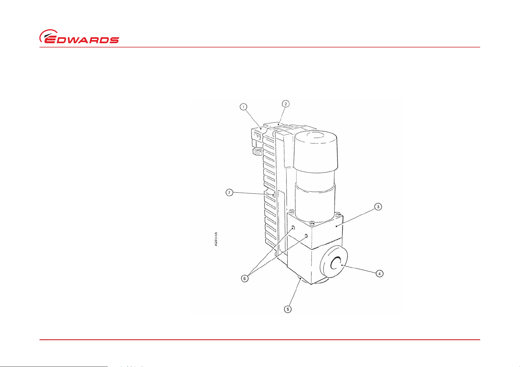
1. Position indicator socket
2. Electrical supply socket
3. Valve-body
4. Valve-port
5. Valve-port
6. Mounting holes
7. Electrical-box
1. Anschluß Stellungsindikator
2. Anschluß Stromversorgung
3. Ventilkörper
4. Ventilöffnung
5. Ventilöffnung
6. Montagelöcher
7. Elektrischer Schaltkasten
C411-02-885 Issue H/Ausgabe H/Version H
Introduction
Figure 1 – PVEK valve (PV10EK right-angled valve shown)
Abbildung 1 – PVEK Ventil (dargestellt wird das Eckventil PV10EK)
Figure 1 – Vanne PVEK (Illustration du modèle PV10EK à angle droit)
1. Prise femelle de l’indicateur de
position
2. Prise femelle de l’alimentation
électrique
3. Corps de la vanne
4. Orifice de la vanne
5. Orifice de la vanne
6. Trous de fixation
7. Coffret électrique
© Edwards Limited 2007. All rights reserved. Page/Seite/Page 3
Edwards and the Edwards logo are trademarks of Edwards Limited.
Page 16

C411-02-885 Issue H/Ausgabe H/Version H
Introduction
1.3 Construction
Refer to the sectional view of the PVEK valve in Figure 7
to identify the item numbers in brackets.
The valve mechanism is a solenoid-operated moving pole
with an integral valve-pad and bellows ass embly (7). The
vacuum system is isolated from atmosphere by a
fluoroelastomer ‘O’ ring static seal (10) and a stainless
steel bellows for dynamic sealing. The valve-pad also
seals against the valve-body with a fluoroelastomer ‘O’
ring (12). The valve-body terminates in two ports with
NW flanges.
A PCB inside the electrical-box (1) controls the valve
actuation. A magnetic reed-switch positioned on the
underside of the PCB provides position indication. The
reed switch has changeover contacts and provides both
normally open and normally closed position indications.
1.3 Aufbau
Die in Klammern angegebenen laufenden Nummern
beziehen sich auf das Schnittbild des PVEK-Ventils in
Abbildung 7.
Der Ventilmechanismus besteht aus ein e m
elektromagnetisch-betriebenen beweglichen Pol mit
einem integrierten Ventilteller und einer
Faltenbalggruppe (7). Das Vakuumsystem ist durch eine
statische O-Ringdichtung aus Fluorelastomer (10) und
einen Edelstahlfaltenbalg zur dynamischen Dichtung von
der Atmosphäre getrennt. Der Ventilteller dichtet
ebenfalls mit einer O-Ringdichtung aus Fluorelastomer
(12) gegen den Ventilkörper ab. Der Ventilkörper hat
zwei Öffnungen mit NW- Flanschen.
Eine Steuerplatine im Inneren des elektrischen
Schaltkastens (1) steuert die Ventilbetätigung. Ein
magnetischer Zungenschalter an der Unterseite der
Schaltplatte sorgt für die Stellungsanzeige. Der
Zungenschalter hat Umschaltkontakte und kann
Stellungsanzeigen als Öffner und als Schließer ausgeben.
1.3 Construction
Les chiffres entre parenthèses correspondent aux
repères de la vue en coupe d’une vanne PVEK (Figure 7).
Le mécanisme de ces vannes est représenté par un pôle
mobile piloté par solénoïde avec un ensemble intégré
bloc de vanne et soufflet (7). Le circuit de vide est isolé
de l’atmosphère par des joints toriques statiques en
fluoroélastomère (10) et un soufflet en acier inoxydable
assure l’étanchéité dynamique. Un joint torique (12) en
fluoroélastomère inséré entre le bloc de la vanne et son
corps assure également une étanchéité entre ces deux
éléments. Le corps de la vanne se termine par deux
orifices à brides NW.
Une CCI implantée à l’intérieur du boîtier électrique (1)
contrôle l’activation de la vanne. Un commutateur à
lame vibrante magnétique est fixé sous cette CCI pour
indiquer la position. Ce commutateur comporte des
contacts inverseurs et signale les deux types possibles de
positions : normalement ouverte ou normalement
fermée.
Page/Seite/Page 4 © Edwards Limited 2007. All rights reserved.
Edwards and the Edwards logo are trademarks of Edwards Limited.
Page 17

C411-02-885 Issue H/Ausgabe H/Version H
Introduction
1.4 Operation
The solenoid coil in the valve has two windings. To open
the valve, both windings are energised. Initially, the
inner high energy or pulse winding provides a high
transient force to open the valve and is then deenergised. The outer low energy or ‘hold’ winding
remains energised to maintain the valve in the open
position with minimum power.
The valve is closed by de-energising the solenoid coil.
When the outer winding is de-energised, the action of
the spring provides rapid positive closure.
1.4 Betrieb
Die elektromagnetische Spule im Ventil hat zwei
Wicklungen. Zum Öffnen des Ventils werden beide
Wicklungen erregt. Zunächst liefert die innere
hochenergetische bzw. Impulswicklung einen hohen
Einschaltstrom zur Öffnung des Ventils und wird dann
abgeschaltet. Die äußere niederenergetische bzw.
,Haltewicklung‘ bleibt erregt, um das Ventil bei
minimalem Stromverbrauch in geöffnetet Stellung zu
halten.
Geschlossen wird das Ventil, indem die
elektromagnetische Spule abgeschaltet wird. Wenn die
äußere Wicklung stromlos ist, sorgt die Federwirkung für
ein schnelles definitives Schließen des Ventils.
1.4 Fonctionnement
La bobine du solénoïde à l’intérieur de la vanne
comporte deux enroulements. Pour ouvrir cette vanne,
ces deux enroulements sont excités. Pour commencer,
l’enroulement interne à haute énergie ou impulsion
fournit une force transitoire élevée qui ouvre la vanne,
avant d’être désexcité. L’enroulement externe à énergie
faible dit de « maintien » reste excité pour conserver la
vanne en position ouverte avec un minimum de courant.
La vanne est refermée par la désexcitation de la bobine
du solénoïde. Lorsque l’enroulement externe est
désexcité, l’action d’un ressort assure une fermeture
définitive et rapide de la vanne.
© Edwards Limited 2007. All rights reserved. Page/Seite/Page 5
Edwards and the Edwards logo are trademarks of Edwards Limited.
Page 18

C411-02-885 Issue H/Ausgabe H/Version H
This page has been intentionally left blank/Leerseite/Cette page est délibérément laissée blanche.
Page/Seite/Page 6 © Edwards Limited 2007. All rights reserved.
Edwards and the Edwards logo are trademarks of Edwards Limited.
Page 19

C411-02-885 Issue H/Ausgabe H/Version H
Technical data
2 Technical data
Note: Unless otherwise specified, all data in this
section refers to both right-angled and in-line
valves.
2.1 Mechanical data
Refer to Table 3.
2.2 Performance, operating and storage conditions
Refer to Table 1.
2.3 Electrical data
Refer to Table 2.
2.4 Materials
The valves are manufactured from the following
materials:
Valve-body
PVEKA Valve HE30TF grade aluminium
PVEKS Valve AISI 304 grade
stainless steel
Bellows AISI 316L stainless steel
‘O’ rings Fluoroelastomer
2 Technische Daten
Hinweis: Wenn nichts anderes angegeben ist, gelten
alle Daten in diesem Abschnitt sowohl für
Eckventile als auch für Durchgangsventile.
2.1 Mecha nische Daten
Siehe Tabelle 3.
2.2 Leistungs-, Betriebs- und
Lagerbedingungen
Siehe Tabelle 1.
2.3 Elektrische Daten
Siehe Tabelle 2.
2.4 Werkstoffe
Die Ventile werden aus folgenden Werkstoffen
hergestellt:
Ventilkörper
PVEKA-Ventil Aluminium
der Qualität HE30TF
PVEKS-Ventil Edelstahl
der Qualität AISI 304
Faltenbalg Edelstahl
der Qualität AISI 316L
O-Ringe Fluorelastomer
2 Caracteristiques
techniques
Note : Sauf indication contraire, toutes les données de
cette section sont valables pour les vannes à
angle droit et les vannes à passage direct.
2.1 Caractéristiques mécaniques
Voir Tableau 3.
2.2 Performances, conditions de
fonctionnement et de stockage
Voir Tableau 1.
2.3 Caractéristiques électriques
Voir Tableau 2.
2.4 Matériaux
Les vannes sont fabriquées à partir des matériaux
constitutifs suivants:
Corps
Vanne PVEKA Aluminium HE30TF
Vanne PVEKS Acier inoxydable
AISI 304
Soufflet Acier inoxydable
AISI 316L
Joints toriques Fluoroélastomère
© Edwards Limited 2007. All rights reserved. Page/Seite/Page 7
Edwards and the Edwards logo are trademarks of Edwards Limited.
Page 20

C411-02-885 Issue H/Ausgabe H/Version H
Technical data
2.5 Legislation and standards
The valves have been designed in compliance with the
following legislation and standards:
z 73/023/EEC – Low Voltage Directive.
z 89/336/EEC – Electromagnetic Compatibility
Directive.
z EN61010 – Safety Requirements for Electrical
Equipment for Measurement, Control and
Laboratory Use – Part 1: General Requirements.
z EN61326: (Industrial Location, Class B Emissions)
– Electrical Equipment for Measurement, Control
and Laboratory Use – EMC requirements.
z EN60529 – Degrees of Protection Provided by
Enclosures (IP Code).
z Pneurop 6606 – Vacuum Flanges and Connections.
2.5 Vorschriften und Normen
Die Ventilkonstruktion erfüllt folgende Vorschriften und
Normen:
z 73/023/EEC – Niederspannungsrichtlinie
z 89/336/EEC – Richtlinie zur elektro-
magnetischen Verträglichkeit
z EN61010 – Sicherheitsanforderungen an
elektrische Ausrüstung für Mess-, Steuer- und
Laboranwendungen – Part 1: General
Requirements
z EN61326: (Industrieller Einsatz, Emissionsklasse
B) – Elektrische Ausrüstung für Mess-, Steuer- und
Laboranwendungen EMV-Anforderungen.
z EN60529 – Schutzklassen von Gehäusen
(IP-Code).
z Pneurop 6606 – Vakuumflansche und
-verbindungen
2.5 Législation et normes
Toutes ces vannes sont conçues conformément à la
législation et aux normes suivantes :
z 73/023/CEE – Directive sur les basses tensions.
z 89/336/CEE – Directive sur la compat ibilité
électromagnétique.
z EN61010 – Règles de sécurité pour appareils
électriques de mesurage, de régulation et de
laboratoire – partie 1 : prescriptions générales
z EN61326 : (Environnement industriel, émissions
de classe B) – Matériels électriques de mesure,
de commande et de laboratoire – Prescriptions
relatives à la CEM.
z EN60529 – Degrés de protection procurés par les
enveloppes (code IP).
z Pneurop 6606 – Brides et connexions de vide.
Page/Seite/Page 8 © Edwards Limited 2007. All rights reserved.
Edwards and the Edwards logo are trademarks of Edwards Limited.
Page 21

Table 1 – Performance, operating and storage conditions
Tabelle 1 – Leistungs-, Betriebs- und Lagerbedingungen
Tableau 1 – Performances, conditions de fonctionnement et de stockage
Ambient temperature (operation)
Umgebungstemperatur (Betrieb)
Température ambiante (fonctionnement)
Ambient temperature (storage)
Umgebungstemperatur (Lagerung)
Température ambiante (stockage)
Ambient humidity (operation)
Umgebungsluftfeuchte (Betrieb)
Humidité ambiante (fonctionnement)
Operating altitude/operating conditions
Betriebshöhe über NN/Betriebsbedingungen
Altitude/conditions de fonctionnement
Molecular conductance (right-angled valve)/
Molekular Leitwert (Eckv e ntil)/
Conductance en régime moléculaire (vanne à angle droit)
Molecular conductance (in-line valve)/
Molekular Leitwert (Durchgangsventil)/
Conductance en régime moléculaire (vanne à passage direct)
Pressure range (valve open)/
Druckbereich (Ventil offen)/
Gamme de pression (vanne ouverte)
Maximum pressure differential (between flanges)
Maximales Druckdifferenzial (zwischen Flanschen)
Pression différentielle maximale (entre brides)
C411-02-885 Issue H/Ausgabe H/Version H
PV10EK PV16EK PV25EK PV40EK
5 – 45 ºC 5 – 45 ºC 5 – 50 ºC 5 – 50 ºC
-30 – 70 ºC -30 – 70 ºC -30 – 70 ºC -30 – 70 ºC
80% decreasing linearly to 50% relative humidity at 40 ºC
80% linear abfallend zu 50% relativer Luftfeuchte bei 40 ºC
80 %, diminution linéaire jusqu’à 50 % d’humidité relative à 40 ºC
Up to 2000 m/For indoor use only
Bis zu 2000 m/Nur für den Innenbetrieb
Jusqu’à 2000 m/utilisation à l’intérieur uniquement
-1
3 l s
–2 l s-16 l s
4 l s
-1
10 l s
-1
-1
34 l s
15 l s
-1
-1
1 x 10⁻⁹ –2.1 x 10³ mbar (absolute/absolut/absolu)
-7
1 x 10
–2.1 x 105 Pa
1 x 10³ mbar
5
Pa
1 x 10
Technical data
© Edwards Limited 2007. All rights reserved. Page/Seite/Page 9
Edwards and the Edwards logo are trademarks of Edwards Limited.
Page 22
C411-02-885 Issue H/Ausgabe H/Version H
Technical data
Table 1 – Performance, operating and storage conditions (continued)
Tabelle 1 – Leistungs-, Betriebs- und Lagerbedingungen (fortgesetzt)
Tableau 1 – Performances, conditions de fonctionnement et de stockage (suite)
PV10EK PV16EK PV25EK PV40EK
Leak rate/Undichtigkeitsrate/Taux de fuite 1 x 10⁻⁹ mbar l s-1, 1 x 10⁻⁷ Pa l s
Maximum cycle frequency (per hour)/
Maximale Zyklusfrequenz (Pro Stunde)/
Fréquence maximale de manoeuvre (par heure)
Nominal lift (mm)
Nominalhub (mm)
Levée nominale (mm)
Time to open (ms)
Öffnungszeit (ms)
Temps d’ouverture (ms)
Time to close (ms)
Schliebzeit (ms)
Temps de fermeture (ms)
Mean time to failure (cycles)
Mittlere Standzeit (Zyklen)
Temps moyen avant apparition de défaillances (MTTF)
400 400 400 400
2.5 2.5 3.8 6.0
40 40 60 80
100 100 100 120
> 5 x 10
5
> 5 x 10
5
-1
> 1.3 x 10
5
> 1.3 x 10
5
Page/Seite/Page 10 © Edwards Limited 2007. All rights reserved.
Edwards and the Edwards logo are trademarks of Edwards Limited.
Page 23

Electrical supply voltage range
Elektrischer Spannungsbereich
Plage de tension d’alimentation
110 V nominal/110 V Nennspannung/110 V nominale
C411-02-885 Issue H/Ausgabe H/Version H
Technical data
Table 2 – Electrical data
Tabelle 2 – Elektrische Daten
Tableau 2 – Caractéristiques électriques
PV10EK PV16EK PV25EK PV40EK
90 – 132 V
240 V nominal/240 V Nennspannung/240 V nominale
Frequency/Frequenz/Fréquence
Continuous power (W)/Dauerleistung (W)/Puissance continue (W)
110 V a.c.
240 V a.c.
Peak power (VA) for 60 ms/Spitzenleistung (VA) für 60 ms/
Puissance de pointe (VA) pour 60 ms
110 V a.c.
240 V a.c.
Reed-switch ratings
Daten Zungenschalter
Caractéristiques nominales de commutateur à lame vibrante
Maximum voltage (peak, a.c. or d.c.)
Maximalspannung (Spitzenwert, We chselstrom oder Gleichstrom)
Tension maximale (pointe, c.a ou c.c.)
Maximum current (peak)/power (r.m.s.)
Maximalstrom (Spitzenwert) / Leistung (eff.)
Intensité maximale (pointe)/puissance maximale (eff)
Electrical supply plug/Netzstecker/Fiche de l’alimentation électrique
Cable diameter/Kabeldurchmesser/Diamètre du câble 6 – 8 mm
Microswitch plug/Mikroschalterstecker/Fiche du microrupteur
Maximum cable diameter
Maximaler Kabeldurchmesser
Diamètre maximal du câble
3.3
4.4
450
560
180 – 264 V
3.3
4.4
450
560
0.25 A/3 VA
50 – 60 Hz
28 V
6.5 mm
6.1
8.2
940
1200
8.0
8.3
1400
2400
© Edwards Limited 2007. All rights reserved. Page/Seite/Page 11
Edwards and the Edwards logo are trademarks of Edwards Limited.
Page 24

C411-02-885 Issue H/Ausgabe H/Version H
Technical data
Dimensions: mm (see Figures 2 and 3 for keys)
Abmessungen: in mm (bzgl. Erläuterungen siehe die Abbildungen 2 und 3)
Dimensions : mm (voir légende des Figures 2 et 3)
Mounting hole thread size and maximum depth
Gewindegröße und maximale Tiefe der Montagelöcher
Filetage et profondeur maximale des orifices de montage
Valve-port flange size
Flanschgröße der Ventilöffnung
Taille de bride d’orifice de vanne
IP ratings (as defined by EN60529): valve enclosure ▲
IP-Daten (gemäß EN60529): Ventilgehäuse ▲
Indices IP (tels que définis par EN60529) : enveloppe de vanne ▲
Mass (kg) PVEKA
Gewicht (kg) IPVEKA
Poids (kg) PVEKS
IPVEKS
▲
The electrical supply connector and the microswitch connector must be connected using the gasket
supplied, and the correct cable diameters must be used, in order to meet the requirements of IP55.
▲ Um den Anforderungen von IP 55 zu entsprechen müssen Netzstecker und Mikroschalterstecker unter
Verwendung der mitgelieferten Manschette verbunden werden und die richtigen Kabeldurchmesser müssen
verwendet werden.
▲ Les connecteurs de l’alimentation électrique et du microrupteur doivent être raccordés à l’aide du
joint fourni, et les diamètres de câble corrects être utilisés pour satisfaire aux exigences d’IP55.
Table 3 – Mechanical data
Tabelle 3 – Mechanische Daten
Tableau 3 – Caractéristiques mécaniques
PV10EK PV16EK PV25EK PV40EK
A
B
C
F
H
L
M
30
42
20
59 * - †
150 * - †
116 * - †
-
M4 x 7 M4 x 7 M4 x 7 M6 x 9
NW10 NW16 NW25 NW40
IP55 IP55 IP55 IP55
0.8 *
- †
0.9
- †
40
42
20
69 * 37.4 †
160 * 142.9 †
126 * 85 †
40 †
0.8 *
0.8 †
1.2
1.2 †
* Right-angled valve/Eckventil/Vanne à angle droit
† In-line valve (note that there is no PV10EK in-line valve)
Durchgangsventil (Es gibt kein PV10EK – Durchgangsventil)
Vanne à passage direct (Note : il n’existe pas de vanne
PV10EK à passage direct)
50
55
20
82 * 72.5 †
182 * 172 †
142 * 93 †
50 †
1.8 *
1.8 †
2.4
2.5 †
65
80
40
110 * 10 1.5 †
230 * 222 †
170 * 111 †
65 †
4.5 *
4.6 †
6.4
6.8 †
Page/Seite/Page 12 © Edwards Limited 2007. All rights reserved.
Edwards and the Edwards logo are trademarks of Edwards Limited.
Page 25

Figure 2 – Right-angled valve dimensions
Abbildung 2 – Abmessungen der Eckventile
Figure 2 – Dimensions de la vanne à angle droit
C411-02-885 Issue H/Ausgabe H/Version H
Technical data
© Edwards Limited 2007. All rights reserved. Page/Seite/Page 13
Edwards and the Edwards logo are trademarks of Edwards Limited.
Page 26

C411-02-885 Issue H/Ausgabe H/Version H
Technical data
Figure 3 – In -l in e valve dime nsi o ns
Abbildung 3 – Abmessungen der Durchgangsventile
Figure 3 – Dimensions de la vanne à passage direct
Page/Seite/Page 14 © Edwards Limited 2007. All rights reserved.
Edwards and the Edwards logo are trademarks of Edwards Limited.
Page 27

C411-02-885 Issue H/Ausgabe H/Version H
Technical data
2.6 Product Item Numbers
2.6.1 Right-angled valves
Product Item Number
Aluminium bodies
PV10EKA Valve (220 V) C411-01-000
PV10EKA Valve (110 V) C411-03-000
PV16EKA Valve (220 V) C412-01-000
PV16EKA Valve (110 V) C412-03-000
PV25EKA Valve (220 V) C413-01-000
PV25EKA Valve (110 V) C413-03-000
PV40EKA Valve (220 V) C414-01-000
PV40EKA Valve (110 V) C414-03-000
Stainless steel bodies
PV16EKS Valve (220 V) C412-02-000
PV16EKS Valve (110 V) C412-04-000
PV25EKS Valve (220 V) C413-02-000
PV25EKS Valve (110 V) C413-04-000
PV40EKS Valve (220 V) C414-02-000
PV40EKS Valve (110 V) C414-04-000
2.6 Artikelnummern
2.6.1 Eckventile
Produkt Artikelnummer
Aluminiumkörper
PV10EKA Ventil (220 V) C411-01-000
PV10EKA Ventil (110 V) C411-03-000
PV16EKA Ventil (220 V) C412-01-000
PV16EKA Ventil (110 V) C412-03-000
PV25EKA Ventil (220 V) C413-01-000
PV25EKA Ventil (110 V) C413-03-000
PV40EKA Ventil (220 V) C414-01-000
PV40EKA Ventil (110 V) C414-03-000
Edelstahlkörper
PV16EKS Ventil (220 V) C412-02-000
PV16EKS Ventil (110 V) C412-04-000
PV25EKS Ventil (220 V) C413-02-000
PV25EKS Ventil (110 V) C413-04-000
PV40EKS Ventil (220 V) C414-02-000
PV40EKS Ventil (110 V) C414-04-000
2.6 Numéro de code des produits
2.6.1 Vannes à angle droit
Produit Numéro de code
Corps en aluminium
Vanne PV10EKA (220 V) C411-01-000
Vanne PV10EKA (110 V) C411-03-000
Vanne PV16EKA (220 V) C412-01-000
Vanne PV16EKA (110 V) C412-03-000
Vanne PV25EKA (220 V) C413-01-000
Vanne PV25EKA (110 V) C413-03-000
Vanne PV40EKA (220 V) C414-01-000
Vanne PV40EKA (110 V) C414-03-000
Corps en acier inoxydable
Vanne PV16EKS (220 V) C412-02-000
Vanne PV16EKS (110 V) C412-04-000
Vanne PV25EKS (220 V) C413-02-000
Vanne PV25EKS (110 V) C413-04-000
Vanne PV40EKS (220 V) C414-02-000
Vanne PV40EKS (110 V) C414-04-000
© Edwards Limited 2007. All rights reserved. Page/Seite/Page 15
Edwards and the Edwards logo are trademarks of Edwards Limited.
Page 28

C411-02-885 Issue H/Ausgabe H/Version H
Technical data
2.6.2 In-line valves
Product Item Number
Aluminium bodies
PV10EKA Valve (220 V) PV10EKA Valve (110 V) PV16EKA Valve (220 V) C416-10-000
PV16EKA Valve (110 V) C416-11-000
PV25EKA Valve (220 V) C416-30-000
PV25EKA Valve (110 V) C416-31-000
PV40EKA Valve (220 V) C416-51-000
PV40EKA Valve (110 V) C416-52-000
Stainless steel bodies
PV16EKS Valve (220 V) C416-12-000
PV16EKS Valve (110 V) C416-13-000
PV25EKS Valve (220 V) C416-32-000
PV25EKS Valve (110 V) C416-33-000
PV40EKS Valve (220 V) C416-53-000
PV40EKS Valve (110 V) C416-54-000
2.6.2 Durchgangsventile
Produkt Artikelnummer
Aluminiumkörper
PV10EKA Ventil (220 V) PVI0EKA Ventil (110 V) PVI6EKA Ventil (220 V) C416-10-000
PVI6EKA Ventil (110 V) C416-11-000
PV25EKA Ventil (220 V) C416-30-000
PV25EKA Ventil (110 V) C416-31-000
PV40EKA Ventil (220 V) C416-51-000
PV40EKA Ventil (110 V) C416-52-000
Edelstahlkörper
PVI6EKS Ventil (220 V) C416-12-000
PV16EKS Ventil (110 V) C416-13-000
PV25EKS Ventil (220 V) C416-32-000
PV25EKS Ventil (110 V) C416-33-000
PV40EKS Ventil (220 V) C416-53-000
PV40EKS Ventil (110 V) C416-54-000
2.6.2 Vannes à passage direct
Produit Numéro de code
Corps en aluminium
Vanne PV10EKA (220 V) Vanne PV10EKA (110 V) Vanne PV16EKA (220 V) C416-10-000
Vanne PV16EKA (110 V) C416-11-000
Vanne PV25EKA (220 V) C416-30-000
Vanne PV25EKA (110 V) C416-31-000
Vanne PV40EKA (220 V) C416-51-000
Vanne PV40EKA (110 V) C416-52-000
Corps en acier inoxydable
Vanne PV16EKS (220 V) C416-12-000
Vanne PV16EKS (110 V) C416-13-000
Vanne PV25EKS (220 V) C416-32-000
Vanne PV25EKS (110 V) C416-33-000
Vanne PV40EKS (220 V) C416-53-000
Vanne PV40EKS (110 V) C416-54-000
Page/Seite/Page 16 © Edwards Limited 2007. All rights reserved.
Edwards and the Edwards logo are trademarks of Edwards Limited.
Page 29

C411-02-885 Issue H/Ausgabe H/Version H
Installation
3Installation
3.1 Unpack and inspect
Remove all the packing materials and protective covers
and check the PVEK valve.
If the valve is damaged, notify your supplier and the
carrier in writing within three days; state the Item
Number of the valve together with your order number
and your supplier’s invoice number. Retain the packing
materials for inspection. Do not use the valve.
If the valve is not to be used immediately, replace the
protective covers. Store the valve in suitable conditions,
as described in Section 6.
3Einbau
3.1 Ventil auspacken und prüfen
Sämtliches Verpackungsmaterial und alle
Schutzabdeckungen entfernen; dann das PVEK-Ventil
prüfen.
Wenn eine Beschädigung des Ventils festgestellt wird, so
müssen Lieferant und Spediteur hiervon innerhalb von
drei Tagen schriftlich in Kenntnis gesetzt werden; dabei
zusammen mit Ihrer Auftrag snummer und der
Rechnungsnummer des Lieferanten die Artikelnummer
des Ventils angeben. Die Verpackungsmaterialien zweck s
späterer Begutachtung aufbewahren. Ein beschädigtes
Ventil darf nicht benutzt werden.
Wenn das Ventil nicht für den sofortigen Einsatz
bestimmt ist, die Schutzabdeckungen wieder anbringen.
Das Ventil bei entsprechend geeigneten Bedingungen
lagern. Siehe Abschnitt 6.
3 Installation
3.1 Déballage et vérifications
Retirez tous les matériaux d’emballage et obturateurs
de protection et vérifiez que la vanne PVEK n’est pas
endommagée.
En cas d’endommagement, vous devez prévenir votre
fournisseur et le transporteur par écrit, dans les trois
jours, en signalant le numéro de code de la vanne ainsi
que votre numéro de commande et le numéro de facture
de votre fournisseur. Conservez les matériaux
d’emballage en vue d’un examen ultérieur. N’utilisez
pas cette vanne si elle est endommagée.
Si la vanne ne doit pas être utilisée immédiatement,
remettez en place les obturateurs de protection et
conservez la vanne dans les conditions adéquates,
comme indiqué à la Section 6.
© Edwards Limited 2007. All rights reserved. Page/Seite/Page 17
Edwards and the Edwards logo are trademarks of Edwards Limited.
Page 30

C411-02-885 Issue H/Ausgabe H/Version H
Installation
3.2 Install the valve
WARNING
Take appropriate safety precautions
when you install the valve in a system in
which dangerous process substances
have been pumped.
WARNING
Fit a cover to any valve-port which is
open to atmosphere. Access to open
ports is dangerous.
CAUTIONCAUTIONCAUTION
We recommend that you provide additional support
for a PV40EKA in-line valve. The valve flanges of an
unsupported PV40EKA in-line valve may be distorted
by the mass of the valve. Alternatively, fit a PV40EKS
in-line valve.
The valve is normally supported by the pipeline it is
fitted to and can be mounted in any orientation. Two
threaded holes in the valve-body allow for additional
support, if required; the dimensions of these holes are
defined in Section 2. Do not exceed the specified
maximum depth of thread or you will damage the valve.
Connect the valve to your vacuum system with standard
NW coupling components.
3.2 Ventil einbauen
WARNUNGWARNUNG
Bei Einbau des Ventils in eine Anlage,
durch die Gefahrstoffe gepumpt worden
sind, müssen entsprechende
Sicherheitsvorkehrungen getroffen
werden.
WARNUNGWARNUNG
Decken Sie jeden zur Atmosphäre
offenen Ventilanschluß ab. Zugang zu
offenen Anschlüssen ist gefährlich.
VORSICHT
Wir empfehlen den Einsatz einer zusätzlichen
Halterung für ein PV40EKA Durchgangs- ventil. Die
Ventilflansche eines PV40EKA Durchgangsventils ohne
Zusatzhalterung können sich durch die Masse des
Ventils verformen. Alternativ wird der Einbau eines
PV40EKS Durchgangsventils empfohlen.
Das Ventil wird üblicherweise von den Rohr- leitungen
gehalten, an denen es angebracht wird, und kann in
jeder Ausrichtung montiert werden. Zwei
Gewindeöffnungen im Ventilkörper ermöglichen
zusätzliche Befestigungsmöglichkeiten, falls
erforderlich; die Abmessungen dieser Öffnungen sind in
Abschnitt 2 angegeben. Gehen Sie nicht über die
festgelegte maximale Gewindetiefe hinaus, da Sie sonst
das Ventil beschädigen. Der Anschluß des Ventil s an da s
Vakuumsystem erfolgt mit standardmäßigen NWKopplungsteilen.
3.2 Installation de la vanne
AVERTISSEMENT
Prenez les mesures appropriées de
sécurité lors de l’installation d’une
vanne dans un circuit dans lequel des
substances dangereuses ont été
pompées.
AVERTISSEMENT
Placez un obturateur sur tous les orifices
de vanne qui sont mis à l’air libre.
L’accès à des orifices ouverts est
dangereux.
ATTENTION
Il est recommandé de prévoir un support
supplémentaire pour une vanne à passage direct
PV40EKA. Si vous ne respectez pas cette consigne,
le poids de la vanne peut déformer les brides. Vous
pouvez également installer une vanne à passage direct
PV40EKS.
Normalement, la vanne est soutenue par la canalisation
sur laquelle elle vient se fixer. Elle peut se monter dans
n’importe quelle position. Deux trous filetés sur le corps
de vanne offrent un support supplémentaire. La
Section 2 donne les côtes de ces trous. Ne dépassez pas
la profondeur maximale spécifiée de filetage pour ne pas
endommager la vanne. Branchez cette vanne sur votre
circuit de vide en utilisant des composants de
raccordement standard NW.
Page/Seite/Page 18 © Edwards Limited 2007. All rights reserved.
Edwards and the Edwards logo are trademarks of Edwards Limited.
Page 31

C411-02-885 Issue H/Ausgabe H/Version H
Installation
If necessary, you can rotate the valve-body from its
standard position (in 90° steps for the right-angled valve
and in 180° steps for the in-line valve). Remove the fou r
screws which secure the solenoid actuating cylinder to
the valve-body and reassemble with the cylinde r turned
in the required direction.
3.3 Electrical connections
WARNING
Ensure that the electrical installation of
the PVEK valve conforms with your local
and national safety requirements. It must
be connected to a suitable fused and
protected electrical supply and a suitable
earth (ground) point.
WARNING
In order to comply with EN61010, the
valve must be connected to a suitable
2 pole circuit breaker which is labelled
appropriately and mounted in close
proximity, within easy reach of the
operator.
Wenn notwendig, können Sie den Ventilkörper aus der
Standardstellung drehen (in 90°-Schritten beim
Eckventil und in 180°-Schritten beim Durchgangsventil).
Entfernen Sie dazu die vier Schrauben, die den
elektromagnetischen Betätigungszylinder am
Ventilkörper halten, und setzen Sie die Einheit mit dem
Zylinder in der gewünschten Richtung wieder zusammen.
3.3 Elektrische Anschlüsse
WARNUNGWARNUNG
Unbedingt darauf achten, daß der
elektrische Einbau des PVEK-Ventils den
örtlichen und nationalen
Sicherheitsvorschriften entspricht. Es
muss an eine geschützte Stromquelle mit
ausreichender Sicherung und eine
geeignete Erdanschlussstelle
angeschlossen sein.
WARNUNGWARNUNG
Gemäß EN61010 muss das Ventil mit
einem geeigneten 2-poligen
Schutzschalter verbunden werden, der
entsprechend gekennzeichnet ist und in
der Nähe, für die Bedienperson leicht zu
erreichen, angebracht ist.
Le cas échéant, vous pouvez faire tourner le corps de la
vanne par rapport à sa position standard (de 90° p our la
vanne à angle droit et de 180° pour la vanne à passage
direct). Retirez les quatre vis qui immobilisent le vérin
de commande du solénoïde sur le corp s de la vanne puis
procédez à un remontage après avoir tourné le cylindre
dans le sens requis.
3.3 Branchements électriques
AVERTISSEMENT
Vérifiez que l’installation électrique de
la vanne PVEK respecte les critères
nationaux et locaux de sécurité. Elle doit
être branchée sur une alimentation
électrique équipée d’un fusible et
protégée, avec point de mise à la terre
(masse).
AVERTISSEMENT
Pour satisfaire à la norme EN61010, la
vanne doit être raccordée à un
disjoncteur bipolaire adéquat,
correctement identifié et monté à
proximité, à portée de l’opérateur.
© Edwards Limited 2007. All rights reserved. Page/Seite/Page 19
Edwards and the Edwards logo are trademarks of Edwards Limited.
Page 32

C411-02-885 Issue H/Ausgabe H/Version H
Installation
1. Electrical-box
2. Sealing-gland
3. Connector block
4. Electrical supply socket
5. Socket retaining screw
6. Cable strain-relief nut
7. Position indicator socket
1. Elektrischer Schaltkasten
2. Dichtungsstopfbuchse
3. Klemmenblock
4. Elektrische Steckbuchse
5. Halteschraube für Buchse
6. Zugentlastungsmutter für Kabel
7. Buchse für Stellungsindikator
Figure 4 – Electrical connectors
Abbildung 4 – Elektrische Anschlüsse
Figure 4 – Connecteurs électriques
1. Coffret électrique
2. Presse-étoupe d’étanchéité
3. Bloc connecteur
4. Prise femelle d’alimentation
électrique
5. Vis de fixation de prise
6. Ecrou de détente de câble
7. Prise femelle de l’indicateur de
position
Page/Seite/Page 20 © Edwards Limited 2007. All rights reserved.
Edwards and the Edwards logo are trademarks of Edwards Limited.
Page 33

1. Live
2. Neutral
3. Earth (ground)
1. Phase
2. Neutral
3. Erdung
C411-02-885 Issue H/Ausgabe H/Version H
Installation
Figure 5 – Electrical supply connections
Abbildung 5 – Netzanschlüsse
Figure 5 – Connexions électriques
1. Phase
2. Neutre
3. Terre (masse)
© Edwards Limited 2007. All rights reserved. Page/Seite/Page 21
Edwards and the Edwards logo are trademarks of Edwards Limited.
Page 34

C411-02-885 Issue H/Ausgabe H/Version H
Installation
3.3.1 Fit your own electrical supply cable
Use the following procedure to fit your own electrical
supply cable to the PVEK valve. Refer to Figure 4 for
item numbers in brackets.
1. Check that the electrical supply corresponds with
the voltage stated on the valve label.
2. Undo the screw (5) and remove the electrical supply
socket (4) from the electrical-box (1). Remove the
sealing-gland (2) and prise out the connector block
(3).
3. Loosen the strain-relief nut (6) and pass the
electrical supply cable through the nut and into the
socket. Refer to Table 2 for information on the
correct cable diameter .
4. Connect the electrical supply cable to the connector
block as shown in Figure 5. Ensure that the earth
(ground) conductor is longer than the other
conductors, so that if the cable is accidentally
dragged, the earth (ground) conductor will be the
last conductor to be pulled from the connector
block.
5. Push the connector block (3) back into the socket;
ensure that it is orientated correctly so that the
sockets mate with the corresponding pins labelled
on the electrical-box (1).
6. Gently pull on the cable to ensure that the cable is
trapped inside the connector. Tighten the strainrelief nut (6).
3.3.1 Anschließen eines eigenen
Netzkabels
Das folgende Verfahren durchführen, um ein eigenes
Netzkabel an das PVEK-Ventil anzuschießen. Siehe
Abbildung 4 bezüglich der in Klammern angegebenen
Teilenummern.
1. Zunächst prüfen, daß die vorhandene Netzspannung
der auf dem Etikett des Ventils angegebenen
Spannung entspricht.
2. Schraube (5) lösen und die elektrische Steckbuchse
(4) vom elektrischen Schaltkasten (1) abnehmen. Die
Dichtungsstopfbüchse (2) abnehmen und den
Klemmenblock (3) heraushebeln.
3. Die Zugentlastungsmutter (6) etwas lösen und das
Netzkabel durch die Mutter hindurch zur
Steckbuchse führen. Informationen zum richtigen
Kabeldurchmesser finden Sie in Tabelle 2.
4. Schließen Sie das Netzkabel wie in Abbildung 5
dargestellt an den Klemmenblock an. Achten Sie
darauf, dass der Nullleiter länger ist als die übrigen
Leiter, so dass bei versehentlichem Ziehen des
Kabels der Nullleiter als letzter aus dem
Klemmenblock gezogen wird.
5. Den Klemmenblock (3) zurück in die Steckbuchse
drücken; dabei auf korrekte Orientierung achten:
die Buchsen in der Steckbuchse müssen so auf die
dazugehörigen Stifte passen, wie in der Beschriftung
des Schaltkastens (1) angegeben.
6. Leicht am Kabel ziehen, um zu prüfen, daß das
Kabel fest im Klemmenblock sitzt. Die
Zugentlastungsmutter (6) festziehen.
3.3.1 Installation de votre propre câble
d'alimentation électrique
Pour brancher votre propre câble d'alimentation
électrique sur la vanne PVEK, respectez la procédure
suivante. Les chiffres entre parenthèses correspondent
aux repères de la Figure 4.
1. Vérifiez que la tension secteur est identique à la
valeur indiquée sur l’étiquette de la vanne.
2. Desserrez la vis (5) puis retirez du coffret électrique
(1) la prise femelle d’alimentation électrique (4).
Resserrez le presse-étoupe d’étanchéité (2 ) puis
extrayez le bloc connecteur (3).
3. Desserrez l’écrou de détente (6) puis faites passer le
câble électrique par cet écrou et introduisez-le dans
la prise. Reportez-vous au Tableau 2 pour plus
d’informations sur les diamètres de câble corrects .
4. Branchez le câble d’alimentation électrique dans le
bloc connecteur, comme illustré à la Figure 5.
Veillez à ce que le conducte ur de masse (terre) soit
plus long que les autres conducteurs, de sorte que si
l’on tire accidentellement sur le câble, le
conducteur de masse soit le dernier à être
débranché du bloc.
5. Enfoncez de nouveau le bloc connecteur (3) dans la
prise. Vérifiez que son orientation est correcte et
que les prises viennent se brancher sur les broches
correspondantes identifiées par une étiquette
apposée sur le coffret électrique (1).
6. Tirez doucement sur le câble pour s’assurer qu’il est
bien coincé à l’intérieur du connecteur. Resserrez
l’écrou de détente (6).
Page/Seite/Page 22 © Edwards Limited 2007. All rights reserved.
Edwards and the Edwards logo are trademarks of Edwards Limited.
Page 35

C411-02-885 Issue H/Ausgabe H/Version H
Installation
7. Refit the sealing-gland (2) over the socket (4) and
push the socket onto the three connector pins on the
electrical-box.
8. Refit the retaining screw (5) and tighten; ensure
that there is a slight compression of the sealinggland.
3.3.2 Fit the electrical supply cable
accessory
Use the following procedure to fit the electrical supply
cable accessory. Refer to Figure 4 for item numbers in
brackets.
The accessory is supplied as a fully assembled cable,
together with a new sealing-gland and socket retaining
screw.
1. Undo the screw (5) and remove the existing
electrical supply socket (4) from the electrical-box
(1) on the valve.
2. Fit the new sealing-gland (2) to the socket (4) on the
electrical supply cable accessory.
3. Push the socket (4) onto the three connector pins on
the electrical-box.
4. Fit the new socket retaining screw (5) and tighten;
ensure that there is a slight compression of the
sealing-gland.
5. Fit the plug on the other end o f the electric al supply
cable accessory to a suitable electrical supply
outlet.
7. Die Dichtungsstopfbüchse (2) wieder über der
Steckbuchse (4) anbringen und die Steckbuchse auf
die drei Anschlußstifte am Elektrokasten drücken.
8. Die Sicherungsschraube (5) wieder einsetzen und
festziehen; darauf achten, daß die
Dichtungsstopfbüchse leicht zusammengedrückt
wird.
3.3.2 Anschließen des
Netzkabelzubehörs
Das folgende Verfahren durchführen, um das
Netzkabelzubehör anzuschließen. Abbildung 4 enthält
die Teilenummern in Klammern.
Das Zubehör wird als komplett montiertes Kabel
zusammen mit einer neuen Dichtungsstopf- buchse und
einer Buchsenhalteschraube ausgeliefert.
1. Die Schraube (5) lösen, und den vorhandenen
Stromversorgungsanschluß (4) vom elektrischen
Schaltkasten (1) am Ventil entfernen.
2. Die neue Dichtungsstopfbuchse (2) an die Buchse (4)
am Netzkabelzubehör montieren.
3. Die Buchse (4) über die drei Anschlußstifte am
elektrischen Schaltkasten schieben.
4. Die neue Buchsenhalteschraube (5) einsetzen und
festziehen. Sicherstellen, daß die
Dichtungsstopfbuchse leicht zusammengedrückt
wird.
5. Den Stecker am anderen Ende des
Netzkabelzubehörs an eine geeignete Steckdose
anschließen.
7. Remettez en place le presse-étoupe d’étanchéité (2)
sur la prise (4) puis enfoncez la prise sur les trois
broches du connecteur du coffret électrique.
8. Remettez en place la vis de fixation (5 ) et vissez-la.
Assurez-vous que le presse-étoupe d’étanchéité est
légèrement comprimé.
3.3.2 Installation du câble
d'alimentation électrique
(accessoire)
Pour installer le câble d'alimentatio n éle ctrique
(accessoire), respectez la procédure suivante. Reporte zvous à la Figure 4 pour les numéros de référence entre
parenthèses.
Le câble est fourni entièrement assemblé, avec une vis
de retenue de douille et un presse-étoupe d'étanchéité
neufs.
1. Desserrez la vis (5) et ôtez la douille d'alimentation
électrique existante (4) du coffret électrique (1) de
la vanne.
2. Installez le nouveau presse-étoupe d'étanchéité (2)
sur la douille (4) du câble d'alimentation électrique.
3. Enfoncez la douille (4) sur les trois broches de
connecteur dans le coffret électrique.
4. Installez la nouvelle vis de retenue de douille (5) et
serrez ; assurez-vous que le presse-étoupe
d'étanchéité est légèrement comprimé.
5. Branchez la fiche à l'autre extrémité du câble
d'alimentation électrique dans une prise de courant
appropriée.
© Edwards Limited 2007. All rights reserved. Page/Seite/Page 23
Edwards and the Edwards logo are trademarks of Edwards Limited.
Page 36

C411-02-885 Issue H/Ausgabe H/Version H
Installation
3.3.3 Position indicator connections
WARNING
Do not use the position indicator as a
safety interlock device. Under certain
circumstances the position indicator may
not operate correctly.
The reed switch position indicator has changeover
contacts and provides both normally open and normally
closed position indications. To use the reed switch
position indicator, connect the terminals as described
below.
1. Undo the screw and remove the position indicator
socket (Figure 4, item 7) from the electrical-box.
Remove the sealing-gland, extract the connector
block and loosen the strain-relief nut.
2. Connect the signal cable to the terminals in the
connector block as shown in Figure 6. Refer to
Table 2 for information on the correct cable
diameter. Do not use the terminal marked with the
earth (ground) symbol.
3. Refit the connector block to the socket and replace
the socket. Note that the socket is not polarised and
can be fitted in any of four possible positions.
Ensure that the sockets mate with the corresponding
pins labelled on the electrical-box.
3.3.3 Anschlüsse des
Stellungsindikators
WARNUNGWARNUNG
Verwenden Sie den Stellungsindikator
nicht als Sicherheitsverriegelung. Unter
bestimmten Umständen kann es
vorkommen, daß der Stellungsindikator
nicht korrekt arbeitet.
Der Zungenschalter hat Umschaltkontakte und kann
Stellungsanzeigen als Öffner und als Schließer ausgeben.
Zum Betrieb des Zungenschalter- Stellungsindikators die
Anschlußklemmen wie nachstehend beschrieben
belegen.
1. Entfernen Sie die Stellungsindikator- Stecker-
buchse (Abbildung 4, lfd. Nr. 7) vom Schaltkasten.
Entfernen Sie die Dichtungsstopfbuchse, nehmen Sie
den Anschlußblock heraus und lösen Sie die
Zugentlastungsmutter.
2. Schließen Sie das Signalkabel an den Anschlüssen de s
Anschlußblocks an, siehe Abbildung 6. Informationen
über den richtigen Kabeldurchmesser finden Sie in
Tabelle 2. Verwenden Sie nicht den Anschluss, der
mit dem Erde-Symbol gekennzeichnet ist.
3. Setzen Sie den Anschlußblock wieder auf die
Steckerbuchse auf und setzen die Steckerbuchse
wieder ein. Beachten Sie, daß die Steckerbuchse
nicht polarisiert ist und in jeder der vier möglichen
Positionen eingesetzt werden kann. Prüfen Sie, daß
die Buchsen auf den entsprechenden Stiften sitzen
(siehe Beschriftung des Schaltkastens).
3.3.3 Branchements d’un indicateur de
position
AVERTISSEMENT
N’utilisez pas l’indicateur de position
comme un dispositif de verrouillage de
sécurité. Dans certains cas, cet
indicateur risque de ne pas fonctionner
correctement.
L’indicateur de position de type commutateur à lame
vibrante comporte des contacts inverseurs et fournit des
indications du type : normalement ouvert et
normalement fermé. Pour utiliser cet indicateur,
branchez ses bornes comme indiqué ci-dessous.
1. Desserrez la vis puis retirez la prise femelle de
l’indicateur de position (repère 7 de la Figure 4) au
niveau du coffret électrique. Déposez le presseétoupe d’étanchéité, extrayez le bloc connecteur
puis desserrez l’écrou de détente.
2. Branchez le câble de signalisation sur les bornes du
bloc connecteur, comme illustré à la Figure 6.
Reportez-vous au Tableau 2 pour plus d’informations
sur les diamètres de câble corrects. N’utilisez pas la
borne identifiée par le symbole de masse (terre).
3. Remontez le bloc connecteur sur la prise femelle
puis remettez en place cette dernière. Il convient de
noter que cette prise n’est pas polarisée et peut
occuper n’importe laquelle des quatre positions
possibles. Vérifiez que les prises femelles viennent
se brancher sur les broches correspondantes
identifiées par une étiquette apposée sur le coffret
électrique.
Page/Seite/Page 24 © Edwards Limited 2007. All rights reserved.
Edwards and the Edwards logo are trademarks of Edwards Limited.
Page 37

1. Normally closed
2. Normally open
3. Common
4. Not used
1. NC (Öffner)
2. NO (Schließer)
3. Masse
4. Nicht belegt
C411-02-885 Issue H/Ausgabe H/Version H
Installation
Figure 6 – Position indicator connections
Abbildung 6 – Anschlüsse des Stellungsindikators
Figure 6 – Branchements d’un indicateur de position
1. Normalement fermé
2. Normalement ouvert
3. Commun
4. Non utilisé
© Edwards Limited 2007. All rights reserved. Page/Seite/Page 25
Edwards and the Edwards logo are trademarks of Edwards Limited.
Page 38

C411-02-885 Issue H/Ausgabe H/Version H
This page has been intentionally left blank/Leerseite/Cette page est délibérément laissée blanche.
Page/Seite/Page 26 © Edwards Limited 2007. All rights reserved.
Edwards and the Edwards logo are trademarks of Edwards Limited.
Page 39

C411-02-885 Issue H/Ausgabe H/Version H
Operation
4Operation
4.1 General
Once correctly installed, operation of the PVEK valve is
dependent only upon the switching of the electrical
supply to the valve.
4.2 Position indicator
WARNING
Do not use the position indicator as a
safety interlock device. Under certain
circumstances the position indicator may
not operate correctly.
Do not rely entirely on the position indicator to indicate
the state of the valve for the following reasons:
z In the event of low electrical supply voltage or a
temporary loss of the electrical supply to the
valve, it is possible for the valve to close but the
position indicator to show the valve still open.
This is because the stray magnetic flux which
remains during a temporary loss of the electrical
supply could be sufficient to hold the reed switch
‘open’.
z If the valve is not able to close due to a physical
obstruction, the position indicator will show the
valve to be closed.
4 Betrieb
4.1 Allgemeines
Nach korrektem Einbau ist der Betrieb des PVEK-Ventils
nur noch davon abhängig, wie die jeweilige
Stromversorgung zum Ventil geschaltet wird.
4.2 Stellungsindikator
WARNUNGWARNUNG
Verwenden Sie den Stellungsindikator
nicht als Sicherheitsverriegelung. Unter
bestimmten Umständen kann es
vorkommen, daß der Stellungsindikator
nicht korrekt arbeitet.
Verlassen Sie sich nicht vollständig auf den
Stellungsindikator, um den jeweiligen Zustand des
Ventils festzustellen. Die Gründe hierfür sind:
z Im Falle einer niedrigen Netzspannung oder eines
vorübergehenden Ausfalles der Stromversorgung
des Ventils, ist es möglich, daß sich das Ventil
schließt, der Stellungsindikator aber ein noch
geöffnetes Ventil anzeigt. Das liegt daran, daß
der magnetische Streufluß, der bei einem
vorübergehenden Ausfall der Stromversorgung
bestehen bleibt, ausreichen könnte, um den
Zungenschalter in ,geöffneter‘ Stellung zu
halten.
z Wenn das Ventil sich aufgrund eines physischen
Hindernisses nicht schließen kann, zeigt der
Stellungsindikator dennoch an, daß das Ventil
geschlossen ist.
4 Fonctionnement
4.1 Généralités
A condition que la vanne PVEK soit correctement
installée, son fonctionnement dépend uniquement de la
commutation de l’alimentation électrique qui aboutit à
ce composant.
4.2 Indicateur de position
AVERTISSEMENT
N’utilisez pas l’indicateur de position
comme un dispositif de verrouillage de
sécurité. Dans certains cas, cet
indicateur risque de ne pas fonctionner
correctement.
Ne vous fiez pas entièrement à un indicateur de po sition
pour connaître l’état de la vanne et ce pour les raisons
suivantes :
z Si la vanne subit une baisse de tension ou une
panne temporaire de courant, il est possible
qu’elle se ferme et, dans ce cas-là, l’indicateur
de position continue de signaler que cette vanne
est ouverte. Cela est dû au fait que le flux de
dispersion magnétique qui reste à la suite d’une
panne temporaire de courant est parfois
suffisant pour maintenir cette lame vibrante en
position « ouverte ».
z Si la fermeture de la vanne est rendue impossible
par un obstacle physique, l’indicateur de
position indique que la vanne est fermée.
© Edwards Limited 2007. All rights reserved. Page/Seite/Page 27
Edwards and the Edwards logo are trademarks of Edwards Limited.
Page 40

C411-02-885 Issue H/Ausgabe H/Version H
Operation
If it is essential to know the state of the valve for safety
reasons, use additional indicators, such as pressure
gauges in the pipelines on each side of the valve.
Aus Gründen der Betriebssicherheit m uß der Zustand des
Ventils bekannt sein; verwenden Sie desha lb zusätzliche
Indikatoren wie z.B. Druckmeßgeräte in den Leitungen
an beiden Seiten des Ventiles.
S’il est vital de connaître l’état de la vanne pour des
raisons de sécurité, il faut utiliser des indicateurs
supplémentaires comme, par exemple, des manomètres
implantés dans des canalisations, de part et d’autre de
la vanne.
Page/Seite/Page 28 © Edwards Limited 2007. All rights reserved.
Edwards and the Edwards logo are trademarks of Edwards Limited.
Page 41

C411-02-885 Issue H/Ausgabe H/Version H
Maintenance
5 Maintenance
5.1 General
PVEK valves do not require routine maintenance during
their normal operational life. If the valve is faulty, refer
to the following sections.
5.1.1 Safety information
WARNING
Obey the safety instructions given below
and take note of appropriate
precautions. If you do not you can cause
injury to people and damage to
equipment.
z Ensure that maintenance is done by a suitably
trained and supervised technician. Obey your
local and national safety requirements.
z Observe all appropriate safety precautions when
you maintain a valve from a system in which
dangerous process substances have been
pumped.
z Isolate the valve from the electrical supply and
your vacuum system before you start
maintenance.
z Observe all appropriate safety precautions when
you come into contact with solvents and
fluoroeleastomer ‘O’ rings.
5Wartung
5.1 Allgemeines
PVEK-Ventile sind während ihres normalen
Betriebslebens wartungsfrei. Wenn das Ventil defekt ist,
siehe die Hinweise in den nachfolgenden Abschnitten.
5.1.1 Sicherheitshinweise
WARNUNGWARNUNG
Beachten Sie die nachstehenden
Sicherheitshinweise und die
entsprechenden Vorsichtsmaßnahmen.
Wenn Sie dies nicht tun, kann das zu
Verletzungen von Personen und
Anlageschäden führen.
z Sorgen Sie dafür, daß Wartungsarbeiten nur
durch einen entsprechend geschulten und
überwachten Techniker durchgeführt werden.
Halten Sie Ihre örtlichen und nationalen
Sicherheitsbestimmungen ein.
z Halten Sie bei der Wartung eines Ventils in einem
System, durch das gefährliche Prozeßsubstanzen
gepumpt worden sind, alle entsprechenden
Sicherheits- vorkehrungen ein.
z Vor Beginn der Wartungsarbeiten das Ventil von
Stromversorgung und Va kuums ystem abklemmen.
z Bei Kontakt mit Lösungsmitteln und O-Ringen aus
Fluorelastomer alle entsprechenden
Sicherheitsvorkehrungen einhalten.
5Entretien
5.1 Généralités
Les vannes PVEK n’ont pas besoin d’entretien courant
tout au long de leur durée de vie normale. Si une vanne
est défectueuse, consultez les paragraphes suivants.
5.1.1 Consignes de sécurité
AVERTISSEMENT
Respectez les consignes de sécurité
indiquées ci-dessous et notez les
précautions à prendre afin d’éviter toute
blessure et tout endommagement.
z Confiez l’entretien à un technicien dûment
formé et correctement supervisé. Respectez les
réglementations locales et nationales de
sécurité.
z Respectez toutes les précautions appropriées de
sécurité lors de l’entretien d’une vanne
exploitée dans un circuit qui a reçu par pompage
des substances dangereuses.
z Coupez l’alimentation électrique de la vanne et
isolez votre circuit de vide avant de commencer
les activités d’entretien.
z Respectez toutes les précautions appropriées de
sécurité au contact de solvants et de joints
toriques en fluoroélastomère.
© Edwards Limited 2007. All rights reserved. Page/Seite/Page 29
Edwards and the Edwards logo are trademarks of Edwards Limited.
Page 42

C411-02-885 Issue H/Ausgabe H/Version H
Maintenance
z Ensure that you do maintenance in a well
ventilated area.
z Do not use abrasive or reactive chemicals to
clean the valve.
z Do not use solvents to clean ‘O’ rings.
z Safely dispose of all components which have
been contaminated by dangerous process
substances.
5.1.2 Fluoroelastomers
The seals and ‘O’ rings used in the PVEK valve are made
from a fluoroelastomer. Fluoroelastomers can
decompose into very dangerous substances if they are
heated to 260 °C and above. The valve may have
overheated if your system has been misused, if it has
malfunctioned or if the valve has been in a fire. If the
valve has overheated, ensure that you observe the
appropriate safety precautions to prevent contact with
the seals and ‘O’ rings.
z Die Wartungsarbeiten in einem gut belüfteten
Bereich durchführen.
z Zur Reinigung des Ve ntils keine scheuernden oder
reaktiven Chemikalien verwenden.
z O-Ringe nicht mit Lösungsmitteln reinigen.
z Alle Komponenten und Bauteile, die durch
gefährliche Prozeßsubstanzen kontaminiert
worden sind, sicher entsorgen.
5.1.2 Fluorelastomere
Die im PVEK-Ventil verwendeten O-Ringe bestehen aus
Fluorelastomer. Fluorelastomere können sich in sehr
gefährliche Substanzen zersetzen, wenn sie auf 260 °C
und darüber erhitzt werden. Überhitzung kann
aufgetreten sein, wenn das Ventil falsch benutzt worden
oder ein Defekt aufgetreten ist bzw. das Ventil einem
Brand ausgesetzt war. Wenn Überhitzung aufgetreten
ist, müssen Sie sicherstellen, daß Sie die entsprechende n
Sicherheitsregeln beachten, um den Kontakt mit den
Dichtungen und O-Ringen zu verhindern.
z Effectuez l’entretien dans une zone bien
ventilée.
z N’utilisez pas de solvant pour nettoyer les joints
toriques.
z Mettez au rebut, en toute sécurité, les
composants qui ont été contaminés par des
substances dangereuses.
5.1.2 Fluoroélastomères
Les joints d’étanchéité et les joints toriques utilisés dans
cette vanne PVEK sont en fluoroélastomère. Les
fluoroélastomères peuvent se décomposer en substances
très dangereuses lorsqu’ils sont soumis à des
températures supérieures ou égales à 260 °C. Une
surchauffe peut se produire à la suite d’une mauvaise
exploitation ou d’un défaut de fonctionnement de votre
système ou lorsque la vanne s’est trouvée dans un
incendie. A la suite d’une telle surchauffe, respectez les
précautions appropriées de sécurité pour éviter tout
contact avec les joints d’étanchéité et les joints
toriques.
Page/Seite/Page 30 © Edwards Limited 2007. All rights reserved.
Edwards and the Edwards logo are trademarks of Edwards Limited.
Page 43

C411-02-885 Issue H/Ausgabe H/Version H
Maintenance
5.2 Dismantle and inspect the valve
CAUTIONCAUTIONCAUTION
When you reassemble the valve, make sure that ‘O’
rings are seated properly in their locating grooves and
are not trapped or pinched.
Note: The best type of grease to use is dependent on
the gases pumped in your system. For ‘clean’
systems, we recommend that you use Fomblin.
Refer to Figure 7 for item numbers shown in brackets.
1. Isolate the valve from the electrical supply.
2. Undo the four retaining screws (9) and remove the
valve-body (11) and the valve-body ‘O’ ring (10)
from the valve.
3. Examine the bellows/pole-piece assembly (7), the
valve-body ‘O’ ring (10) and the valve-pad ‘O’ ring
(12) for damage and wear.
4. If necessary, replace any worn or damaged items as
described in Sections 5.3 and 5.4.
5. Refit the bellows assembly into the actuator-case;
ensure free movement of the pole-piece in the
actuator-case.
6. Refit the valve-body (11) to the valve; secure in
place with the four retaining screws (9) and a
suitable locking adhesive such as Locktite 222.
5.2 Ventil zerlegen und prüfen
VORSICHT
Beim Zusammenbau des Ventils auf richtigen Sitz der
O-Ringe in ihren Aufnahmerillen achten und darauf,
daß sie nicht eingeklemmt oder gequetscht werden.
Hinweis: Welches das beste Fett für Ihr System ist,
hängt von den durch Ihr System gepumpten
Gasen ab. Bei ,sauberem‘ System empfehlen
wir die Verwendung von Fomblin.
Siehe Abbildung 7 bezüglich der in Klammern
angegebenen Teilenummern.
1. Das Ventil von der Stromversorgung trennen.
2. Die vier Halteschrauben (9) lösen und den
Ventilkörper (11) und den O-Ring des Ventilkörpers
(10) vom Ventil a bnehmen.
3. Die Faltenbalg-/Polstückgruppe (7), den O-Ring des
Ventilkörpers (10) und den O-Ring des Ventiltellers
(12) auf Beschädigung und Abnutzung prüfen.
4. Falls erforderlich, abgenutzte und/oder beschädigte
Teile, wie in den Abschnitten 5.3 und 5.4
beschrieben, austauschen.
5. Die Faltenbalggruppe wieder in das Stellgliedgehäuse einbauen; auf freie Beweglichkeit des
Polstücks im Stellgliedgehäuse achten.
6. Den Ventilkörper (11) wieder am Ventil anbringen;
mit den vier Halteschrauben (9) und einem
geeingneten Feststellkleber wie Loctite 222
befestigen.
5.2 Démontage et examen de la
vanne
ATTENTION
Lors du remontage de la vanne, assurez-vous que les
joints toriques reposent correctement dans leur gorge
de centrage et ne sont pas coincés ou pincés.
Note : le meilleur type de graisse à employer dépend
des gaz pompés dans votre circuit. Pour des
circuits « propres », nous vous recommandons
d’utiliser des produits Fomblin.
Les chiffres entre parenthèses correspondent aux
numéros de repères de la Figure 7.
1. Débranchez la prise électrique de la vanne.
2. Desserrez les quatre vis de fixation (9) puis retirez le
corps de la vanne (11) et le joint torique (10).
3. Examinez l’ensemble soufflet/pôle mobile (7), le
joint torique du corps de la vanne (10) et le joint
torique du bloc de la vanne (12) pour vous assurer
qu’il n’y a pas d’endommagement ou d’usure.
4. Le cas échéant, remplacez les articles usés ou
endommagés, comme indiqué aux paragraphes 5.3
et 5.4.
5. Remontez l’ensemble soufflet dans le carter de
l’actionneur. Assurez-vous que le pôle mobile se
déplace librement dans ce carter.
6. Remontez le corps (11) sur la vanne. Immobi- lisez-
le en position avec les quatres vis de fixation (9) et
un adhésif approprié de freinage come, par
exemple, du Loctite 222.
© Edwards Limited 2007. All rights reserved. Page/Seite/Page 31
Edwards and the Edwards logo are trademarks of Edwards Limited.
Page 44

C411-02-885 Issue H/Ausgabe H/Version H
Maintenance
Figure 7 – Sectional view of PVEK valve: key
Abbildung 7 – Schnittbild des PVEK-Ventils: Legende
Figure 7 – Vue en coupe d’une vanne PVEK : légende
A. Detail of in-line valve
1. Electrical box
2. Top cap
3. Sorbathane pad
4. Bearing assembly
5. Fixed pole
6. Coil
7. Bellows/pole-piece assembly
8. Actuator housing
9. Retaining screw
10.Valve-body ‘O’ ring
11.Valve-body
12.Valve-pad ‘O’ ring
A. Detaildarstellung des Durchgangsventils
1. Elektrischer Schaltkasten
2. Haube
3. Sorbathan-Kissen
4. Lagerbaugruppe
5. Festes Polstück
6. Spule
7. Faltenbalg-/Polstückgruppe
8. Stellgliedgehäuse
9. Halteschraube
10.O-Ring des Ventilkörpers
11.Ventilkörper
12.O-Ring des Ventiltellers
A. Détails d’une vanne à passage direct
1. Coffret électrique
2. Chapeau supérieur
3. Garniture Sorbathane
4. Palier
5. Tige fixe
6. Bobine
7. Ensemble soufflet/pôle mobile
8. Logement de l’actionneur
9. Vis de fixation
10.Joint torique du corps de la vanne
11.Corps de la vanne
12.Joint torique du bloc de la vanne
Page/Seite/Page 32 © Edwards Limited 2007. All rights reserved.
Edwards and the Edwards logo are trademarks of Edwards Limited.
Page 45

Figure 7 – Sectional view of PVEK valve
Abbildung 7 – Schnittbild eines PVEK-Ventils
Figure 7 – Vue en coupe d’une vanne PVEK
C411-02-885 Issue H/Ausgabe H/Version H
Maintenance
© Edwards Limited 2007. All rights reserved. Page/Seite/Page 33
Edwards and the Edwards logo are trademarks of Edwards Limited.
Page 46

C411-02-885 Issue H/Ausgabe H/Version H
Maintenance
5.3 Replace the bellows/pole-piece assembly
Refer to Figure 7 for item numbers shown in brackets.
1. Dismantle the valve as described in Section 5.2.
2. Remove the old bellows/pole-piece assembly (7) and
discard.
3. Fit the new valve-pad ‘O’ ring (12) to the new
bellows assembly; apply a light wipe of high vacuum
grease to ease the fit.
4. Fit the bellows assembly into the actuator-case;
ensure free movement of the pole-piece in the
actuator-case.
5. Reassemble the valve as described in Section 5.2.
5.3 Austausch der Faltenbalg-/
Polstückgruppe
Siehe Abbildung 7 bezüglich der in Klammern
angegebenen Teilenummern.
1. Das Ventil wie in Abschnitt 5.2 beschrieben
zerlegen.
2. Die alte Faltenbalg-/Polstückgruppe (7)
herausnehmen und entsorgen.
3. Den neuen O-Ring des Ve ntiltellers (12) an der neuen
Faltenbalggruppe anbringen; zur leichteren Passung
mit einer dünnen Schicht Hochvakuumfett
schmieren.
4. Die Faltenbalggruppe in das Stellergehäuse
einsetzen; auf freie Beweglichkeit des Polstücks im
Stellergehäuse achten.
5. Das Ventil wieder zusammenbauen, wie in
Abschnitt 5.2 beschrieben.
5.3 Remise en place de l’ensemble
soufflet/pôle mobile
Les chiffres entre parenthèses correspondent aux
numéros de repères de la Figure 7.
1. Démontez la vanne comme indiqué au Section 5.2.
2. Déposez puis mettez au rebut l’ensemble soufflet/
pôle mobile (7) usagé.
3. Mettez en position un joint torique neuf de bloc de
vanne (12) sur l’ensemble soufflet neuf. Enduisez
légèrement ces composants de graisse pour vide
poussé pour faciliter cette opération.
4. Introduisez l’ensemble soufflet dans le carter de
l’actionneur. Assurez-vous que le pôle mobile se
déplace librement dans ce carter.
5. Remontez la vanne comme indi qué au Section 5.2.
Page/Seite/Page 34 © Edwards Limited 2007. All rights reserved.
Edwards and the Edwards logo are trademarks of Edwards Limited.
Page 47

C411-02-885 Issue H/Ausgabe H/Version H
Maintenance
5.4 Replace the valve-body and pad ‘O’ rings
Refer to Figure 7 for item numbers shown in brackets.
1. Dismantle the valve as described in Section 5.2.
2. Remove the valve-body ‘O’ ring (10) from the valve-
body and discard.
3. Inspect the ‘O’ ring groove and contact surfaces.
Refinish any surfaces which are damaged.
4. Fit the new valve-body ‘O’ ring (10) to the valve-
body.
5. Remove the bellows/pole-piece assembly (7).
6. Remove and discard the valve-pad ‘O’ ring (12) from
the bellows/pole-piece assembly.
7. Inspect the ‘O’ ring groove and contact surfaces.
Refinish any surfaces which are damaged.
8. Fit the new valve-pad ‘O’ ring to the bellows/pole-
piece assembly; apply a light wipe of high vacuum
grease to ease the fit.
9. Refit the bellows/pole-piece assembly and
reassemble the valve as described in Section 5.2.
5.4 Austausch der O-Ringe von
Ven tilkörper und Ventilteller
Siehe Abbildung 7 bezüglich der in Klammern
angegebenen Teilenummern.
1. Das Ventil wie in Abschnitt 5.2 beschrieben
zerlegen.
2. Den O-Ring des Ventilkörpers (10) vom Ventilkörper
abnehmen und entsorgen.
3. Die Paßrille für den O-Rings sowie die
Kontaktflächen prüfen. Beschädigte Oberflächen
neu bearbeiten.
4. Den neuen O-Ring des Ventilkörpers (10) am
Ventilkörper anbringen.
5. Die Faltenbalg-/Polstückgruppe (7) herausnehmen.
6. Den O-Ring des Ventiltellers (12) aus der Faltenbalg-
/Polstückgruppe herausnehmen und entsorgen.
7. Die Paßrille für den O-Rings sowie die
Kontaktflächen prüfen. Beschädigte Oberflächen
neu bearbeiten.
8. Den neuen O-Ring des Ventiltellers an der
Faltenbalg-/Polstückgruppe anbringen; zur
leichteren Passung mit einer dünnen Schicht
Hochvakuumfett schmieren.
9. Die Faltenbalg-/Polstückgruppe einbauen und das
Ventil, wie in Abschnitt 5.2 beschrieben, wieder
zusammenbauen.
5.4 Replacement des joints
toriques du corps et du bloc
de la vanne
Les chiffres entre parenthèses correspondent aux
numéros de repères de la Figure 7.
1. Démontez la vanne, comme indiqué au Section 5.2.
2. Déposez puis mettez au rebut le joint torique (10)
du corps de la vanne.
3. Examinez la gorge de centrage du joint torique et
les surfaces de contact. Retouchez les surfaces qui
sont endommagées.
4. Mettez en place un joint torique neuf (10) sur le
corps de la vanne.
5. Déposez l’ensemble soufflet/pôle mobile (7).
6. Retirez de l’ensemble soufflet/pôle mobile le joint
torique du bloc de la vanne (12) puis mettez ce joint
au rebut.
7. Examinez la gorge de centrage du joint torique et
les surfaces de contact. Retouchez les surfaces qui
sont endommagées.
8. Mettez en position un joint torique neuf de bloc de
vanne sur l’ensemble soufflet/pôle mobile. Enduisez
légèrement ces composants de graisse pour vide
poussé pour faciliter cette opération.
9. Remettez en place l’ensemble soufflet/pôle mobile
puis remontez la vanne, comme indiqué au
Section 5.2.
© Edwards Limited 2007. All rights reserved. Page/Seite/Page 35
Edwards and the Edwards logo are trademarks of Edwards Limited.
Page 48

C411-02-885 Issue H/Ausgabe H/Version H
Maintenance
5.5 Electrical service kit
WARNING
Do not attempt to open the electrical
box. Hazardous voltages present inside
the electrical box may cause death or
serious injury.
WARNING
The printed circuit assembly should only
be replaced by a service engineer or a
suitably trained and supervised
technician.
An electrical service kit containing a replacement
printed circuit assembly is available as a spare: refer to
Section 7.3.
5.5 Austausch des elektrischen
Sicherungeinsatzes
WARNUNGWARNUNG
Versuchen Sie nicht, den elektrischen
Schaltkasten. zu öffnen. Innerhalb des
elektrischen Schaltkastens vorhandene
gefährliche Spannungen können zum Tod
oder zu schweren Verletzungen führen.
WARNUNGWARNUNG
Die bestückte Leiterplatte sollte nur von
einem Kundendienstingenieur oder
einem entsprechend geschulten und
überwachten Techniker ersetzt werden.
Ein elektrischer Wartungssatz mit einer bestückten
Ersatzleiterplatte ist als Ersatzteil erhältlich: siehe
Abschnitt 7.3.
5.5 Remplacement du fusible de
protection contre les
surtensions
AVERTISSEMENT
Ne tentez pas d’ouvrir le coffret
électrique. Les tensions dangereuses
qu’il contient peuvent être mortelles ou
occasionner des blessures graves.
AVERTISSEMENT
Seul un technicien d’entretien ou un
technicien dûment qualifié est habilité à
remplacer le circuit imprimé.
Un kit de maintenance électrique contenant un circuit
imprimé de rechange est disponible séparément (voir
Section 7.3).
Page/Seite/Page 36 © Edwards Limited 2007. All rights reserved.
Edwards and the Edwards logo are trademarks of Edwards Limited.
Page 49

C411-02-885 Issue H/Ausgabe H/Version H
5.6 Fault finding/Verwendung des elektrischen Wartungssatzes/Utilisation du kit d’entretien électrique
Table 4 – Fault finding
Tabelle 4 – Fehlersuche
Tableau 4 – Recherche des causes de pannes
Symptom/Symptom/Symptôme Check/Prüfen/Vérification Action/Maßnahmnen/Remède
The valve fails to operate.
Das V entil arbeitet nicht.
La vanne refuse de fonctionner.
Has the electrical supply failed?
Ist die Stromversorgung ausgefallen?
Il y a eu une panne de courant.
Check the electrical supply and repair as necessary.
Stromversorgung prüfen und ggfs. reparieren.
Vérifiez l’alimentation électrique et procédez aux
réparations nécessaires.
Maintenance
Is there a loose connection in the electrical supply socket?
Gibt es eine lose Verbindung in der Netzanschlußbuchse?
Il y a un faux contact dans la prise femelle d’alimentation
électrique.
Is the valve obstructed?
Ist das Ventil durch einen Fremdkörper blockiert?
La vanne est bloquée.
Remove the electrical supply socket, check the electrical
supply cable to socket connections and repair as
necessary (see Section 3.3.1).
Die Netzanschlußbuchse ausbauen, die Anschlüsse des
Netzkabels an die Buchse prüfen und wie erforderlich
reparieren (siehe Abschnitt 3.3.1).
Déposez cette prise femelle, vérifiez les raccordements
entre le câble et cette prise et procédez aux réparations
nécessaires (voir Section 3.3.1).
Dismantle the valve (see Section 5.2) and remove the
obstruction.
Das Ventil zerlegen (siehe Abschnitt 5.2) und das
Hindernis entfernen.
Démontez cette vanne (voir Section 5.2) et éliminez la
cause de ce blocage.
© Edwards Limited 2007. All rights reserved. Page/Seite/Page 37
Edwards and the Edwards logo are trademarks of Edwards Limited.
Page 50

C411-02-885 Issue H/Ausgabe H/Version H
Maintenance
Table 4 – Fault finding (continued)
Tabelle 4 – Fehlersuche (Fortsetzung)
Tableau 4 – Recherche des causes de pannes (suite)
Symptom/Symptom/Symptôme Check/Prüfen/Vérification Action/Maßnahmnen/Remède
Incorrect position indication.
Falsche Stellungsanzeige.
Une position incorrecte est indiquée.
Is there a loose connection in the position indication
socket?
Gibt es eine lose Verbindung in der StellungsindikatorBuchse?
Faux contact dans la prise femelle de l’indicateur de
position.
Remove the socket, check the cable to socket connections and
repair as necessary (see Section 3.3.1).
Die Buchse ausbauen, die Anschlüsse des Kabels an die Buchse
prüfen und wie erforderlich reparieren (siehe Abschnitt 3.3.1).
Déposez cette prise, vérifiez les branchements entre le câble
et cette prise et procédez aux réparations néces saires (voir
Section 3.3.1).
Is the electrical supply voltage low?
Ist die Versorgungsspannung niedrig?
La tension d’alimentation est faible.
Is the valve obstructed?
Ist das V entil durch einen Fremdkörper blockiert?
Il y a un faux contact dans la prise femelle d’alimentation
électrique.
Change the electrical supply (see Section 4.2).
Die Stromversorgung ändern (siehe Abschnitt 4.2).
Changez la source d’alimentation électrique (voir Section 4.2).
Dismantle the valve (see Section 5.3) and remove the
obstruction.
Das Ventil zerlegen (siehe Abschnitt 5.3) und das Hindernis
entfernen.
Démontez cette vanne (voir Section 5.3) et éliminez la cause
de ce blocage.
Page/Seite/Page 38 © Edwards Limited 2007. All rights reserved.
Edwards and the Edwards logo are trademarks of Edwards Limited.
Page 51

Table 4 – Fault finding (continued)
Tabelle 4 – Fehlersuche (Fortsetzung)
Tableau 4 – Recherche des causes de pannes (suite)
Symptom/Symptom/Symptôme Check/Prüfen/Vérification Action/Maßnahmnen/Remède
The valve leaks
Das Ventil ist undicht.
La vanne fuit.
Is the valve-body ‘O’ ring or seating groove damaged?
Sind der O-Ring des Ventilkörpers oder die Paßrille
beschädigt?
Le joint torique du corps de la vanne ou la gorge de
centrage de ce joint est endommagé.
Dismantle the valve and check the ‘O’ ring and seating groove
(see Section 5.2).
Refinish and/or replace as necessary.
Das Ventil zerlegen und den O-Ring und die Paßrille prüfen (siehe
Abschnitt 5.2).
Nach Erfordernis neu bearbeiten und/oder austauschen.
Démontez la vanne pour vérifier le joint torique et sa gorge de
positionnement (Section 5.2).
Procédez aux retouches et/ou remplacements nécessaires.
C411-02-885 Issue H/Ausgabe H/Version H
Maintenance
Is the valve-pad ‘O’ ring or seating groove damaged?
Sind der O-Ring des Ventiltellers oder die Paßrille
beschädigt?
Le joint torique du bloc de la vanne ou la gorge de
centrage de ce joint est endommagé.
Is there a bellows leak?
Ist der Faltenbalg undicht?
Le soufflet fuit.
© Edwards Limited 2007. All rights reserved. Page/Seite/Page 39
Edwards and the Edwards logo are trademarks of Edwards Limited.
Dismantle the valve and check the ‘O’ ring and seating groove
(see Section 5.2).
Refinish and/or replace as necessary.
Das Ventil zerlegen und den O-Ring und die Paßrille prüfen
(siehe Abschnitt 5.2).
Nach Erfordernis neu bearbeiten und/oder austauschen.
Démontez la vanne pour vérifier le joint torique et sa gorge de
positionnement (voir Section 5.2).
Procédez aux retouches et/ou remplacements nécessaires.
Replace the bellows/pole-piece assembly (see Section 5.3).
Die Faltenbalg-/P olstückgruppe (siehe Abschnitt 5.3) austauschen.
Remplacez l’ensemble soufflet/pôle mobile, comme indiqué au
Section 5.3.
Page 52

C411-02-885 Issue H/Ausgabe H/Version H
This page has been intentionally left blank/Leerseite/Cette page est délibérément laissée blanche.
Page/Seite/Page 40 © Edwards Limited 2007. All rights reserved.
Edwards and the Edwards logo are trademarks of Edwards Limited.
Page 53

C411-02-885 Issue H/Ausgabe H/Version H
Storage and disposal
6Storage and
disposal
6.1 Storage
Isolate the valve from the electrical supply and
disconnect it from your vacuum system. Place protective
covers over the valve-ports and store the PVEK valve in
cool, dry conditions until it is required for use.
When required, prepare and install the valve as
described in Section 3.
6.2 Disposal
Dispose of the valve and any components rem oved from
it safely in accordance with all local and national sa fety
and environmental requirements.
Particular care must be taken with the following:
z Fluoroelastomers which may have been
subjected to temperatures above 260 ºC
(see Section 5.1.2).
z Components which have been contaminated with
dangerous process substances.
6 Lagerung und
Entsorgung
6.1 Lagerung
Das Ventil von der Stromversorgung isolieren und vom
Vakuumsystem trennen. Die Ventilöffnungen mit
Schutzabdeckungen verschließen und das PVEK-Ventil
kühl und trocken lagern, bis es gebraucht wird.
Bei Bedarf erfolgen Vorbereitung und Einbau des Ventils
wie in Abschnitt 3 beschrieben.
6.2 Entsorgung
Das Ventil und alle von ihm abgebauten Teile und
Komponenten nur unter Einhaltung aller örtlichen und
nationalen Sicherheits- und Umweltvorschriften sicher
entsorgen.
Besondere Vorsicht ist bei folgenden Komponenten
geboten:
z Fluorelastomere, die Temperaturen über 260 ºC
ausgesetzt gewesen sein können (siehe
Abschnitt 5.1.2).
z Komponenten, die durch gefährliche
Prozeßsubstanzen kontami niert worden sind.
6 Stockage et mise
au rebut
6.1 Stockage
Débranchez la prise électrique de la vanne puis
débranchez la vanne de votre circuit de vide. Mettez des
obturateurs de protection sur les orifices de la vanne.
Conservez la vanne PVEK dans un lieu frais et sec jusqu’à
ce que vous en ayez besoin.
A ce moment-là, préparez et installez cette vanne,
comme indiqué à la Section 3.
6.2 Mise au rebut
Vous devez vous débarrasser de cette vanne et de tous
les composants qui en ont été retirés, en respectant
toutes les réglementations locales et nationales en
matière de sécurité et de protection de
l’environnement.
En particulier, il faudra faire très attention aux éléments
suivants :
z Les fluoroélastomères qui ont été soumis à des
températures supérieures à 260 ºC (voir
Section 5.1.2).
z Les composants qui ont été contaminés par des
substances dangereuses.
© Edwards Limited 2007. All rights reserved. Page/Seite/Page 41
Edwards and the Edwards logo are trademarks of Edwards Limited.
Page 54

C411-02-885 Issue H/Ausgabe H/Version H
This page has been intentionally left blank/Leerseite/Cette page est délibérément laissée blanche.
Page/Seite/Page 42 © Edwards Limited 2007. All rights reserved.
Edwards and the Edwards logo are trademarks of Edwards Limited.
Page 55

C411-02-885 Issue H/Ausgabe H/Version H
Service, spares and accessories
7 Service, spares
and accessories
7.1 Introduction
Edwards products, spares and accessories are available
from Edwards companies in Belgium, Brazil, China,
France, Germany, Israel, Italy, Japan, Korea, Singapore,
United Kingdom, U.S.A. and a world-wide network of
distributors.
The majority of these centres employ Service Engineers
who have undergone comprehensive Edwards training
courses.
Order spare parts and accessories from your nearest
Edwards company or distributor. When you order, p lease
state for each part required:
z Model and Item Number of your equipment
z Serial number (if any)
z Item Number and description of the part
7 Kundendienst
Ersatzteile und
Zubehör
7.1 Einleitung
Die Produkte, Ersatz- und Zubehörteile von Edwards sind
über Edwards-Niederlassungen in Belgien, Brasilien,
China, Deutschland, Frankreich, Großbritannien, Israel,
Italien, Japan, Korea, Singapur und den USA sowie ein
weltweites Netz von Vertriebsfirmen erhältlich.
Die Mehrzahl dieser Unternehmen beschäftigt
Wartungstechniker, die bei Edwards an umfassenden
Schulungskursen teilgenommen haben.
Ersatzteile und Zubehör können Sie bei der
nächstgelegenen Edwards-Niederlassung oder
Vertriebsfirma bestellen. Machen Sie bei der Bestellung
für jedes von Ihnen gewünschte Teil folgende Angaben:
z Modell und Bestellnummer Ihrer Ausrüstung
z Seriennummer (sofern vorhanden)
z Bestellnummer und Bezeichnung des Teils
7 Service, pièces
détachées et
accessoires
7.1 Introduction
Les produits, pièces détachées et accessoires Edwards
s’obtiennent en s’adressant à différentes sociétés
Edwards implantées en Belgique, au Brésil, en Chine, en
France, en Allemagne, en Israël, en Italie, au Japon, en
Corée, à Singapour, au Royaume-Uni, aux Etats-Unis
ainsi qu’à un réseau international de distributeurs.
La majorité de ces centres emploient des ingénieurs et
techniciens d’après-vente qui ont suivi des cours très
complets de formation dans des établissements Edwards.
Commander les pièces de rechange et les accessoires en
vous adressant à la société Edwards ou au distributeur
Edwards le plus proche. A lors de votre commande ,
veuillez indiquer, pour chaque composant demandé, les
renseignements suivants :
z Numéro de modèle et de code de votre
équipement
z Numéro de série (le cas échéant)
z Numéro de code et désignation de la pièce
© Edwards Limited 2007. All rights reserved. Page/Seite/Page 43
Edwards and the Edwards logo are trademarks of Edwards Limited.
Page 56

C411-02-885 Issue H/Ausgabe H/Version H
Service, spares and accessories
7.2 Service
Edwards products are supported by a world-wide
network of Edwards Service Centres. Each Service
Centre offers a wide range of options including:
equipment decontamination; service exchange; repair;
rebuild and testing to factory specifications. Equipment
which has been serviced, repaired or rebuilt is returned
with a full warranty.
Your local Service Centre can also provide Edwards
engineers to support on-site maintenance, service or
repair of your equipment.
For more information about service options, contact
your nearest Service Centre or other Edwards company.
7.3 Spares
See Table 5.
7.2 Kundendienst
Edwards verfügt über eine weltweites Netz von
Kundendienstzentren, mit dem alle Produkte von
Edwards unterstützt werden. Jedes
Kundendienstzentrum bietet Ihnen ein breites
Serviceangebot. Dazu zählt: die Dekontamination von
Geräten, das routinemäßige Austauschen, die Reparatur,
das Überholen und Prüfen auf Einhaltung der
Werksspezifkationen. Alle Geräte, die gewartet,
repariert oder überholt wurden, werden mit voller
Garantiegewährung wieder an unsere Kunden
zurückgesandt.
Das Kundendienstzentrum in Ihrer Nähe stellt Ihnen auch
Edwards-Wartungstechniker zur Verfügung, die die
Wartung, den Service oder die Reparatur Ihrer Geräte
vor Ort durchführen.
Für weitere Informationen zu unseren
Kundendienstleistungen wenden Sie sich bitte an das
nächste Kundendienstzentrum oder direkt an Edwards.
7.3 Ersatzteile
Siehe Tabelle 5.
7.2 Service
Les produits Edwards bénéficient de l’assistance du
réseau mondial des Centres de service Edw ards. Chaque
Centre de service offre une large gamme de services,
entre autres : décontamination des équipements,
échange standard ; réparation ; reconstruction et test
selon les spécifications du fabricant. Les équipements
ayant été maintenus, réparés ou reconstruits sont
retournés avec une garantie totale.
Votre Centre de service local pourra aussi mettre à votre
disposition des techniciens Edwards pouvant assurer d es
services de maintenance, de service ou de réparation de
vos équipements.
Pour plus d’informations sur les différents services
disponibles, contactez votre Centre de service le plus
proche ou une autre société Edwards.
7.3 Pièces détachées
Consulter le Tableau 5.
Page/Seite/Page 44 © Edwards Limited 2007. All rights reserved.
Edwards and the Edwards logo are trademarks of Edwards Limited.
Page 57

Table 5 – Spares
Tabelle 5 – Ersatzteile
Tableau 5 – Pièces détachées
C411-02-885 Issue H/Ausgabe H/Version H
Service, spares and accessories
Valve type
Ventiltyp
Type de vanne
PV10EKA (220 V)
PV10EKA (110 V)
PV16EKA (220 V)
PV16EKA (110 V)
PV25EKA (220 V)
PV25EKA (110 V)
PV40EKA (220 V)
PV40EKA (110 V)
PV16EKS (220 V)
PV16EKS (110 V)
PV25EKS (220 V)
PV25EKS (110 V)
PV40EKS (220 V)
PV40EKS (110 V)
‘O’ ring service kit
O-Ring-Wartungssatz
Jeu de maintenance de joints
toriques
Right-angled
valve/
Rechtwinkliges
Ventil/
Vanne à angle
droit
C411-01-800
C411-01-800
C411-01-800
C411-01-800
C413-01-800
C413-01-800
C414-01-800
C414-01-800
C411-01-800
C411-01-800
C413-01-800
C413-01-800
C414-01-800
C414-01-800
In-line valve/
Gerade
durchgehendes
Ventil/
V anne à coulement
rectiligne
C411-01-800
C411-01-800
C413-01-800
C413-01-800
C414-01-800
C414-01-800
C411-01-800
C411-01-800
C413-01-800
C413-01-800
C414-01-800
C414-01-800
Electrical service kit
Elektrischer Wartungssatz
Jeu de maintenance électrique
Right-angled
valve/
Rechtwinkliges
Ventil/
V anne à angle
droit
-
-
C411-01-806
C411-01-805
C411-01-806
C411-01-805
C413-01-806
C413-01-805
C414-01-806
C414-01-805
C411-01-806
C411-01-805
C413-01-806
C413-01-805
C414-01-806
C414-01-805
In-line valve/
Gerade
durchgehendes
Ventil/
Vanne à coulement
rectiligne
-
C411-01-806
C411-01-805
C413-01-806
C413-01-805
C414-01-806
C414-01-806
C411-01-806
C411-01-805
C413-01-806
C413-01-805
C414-01-806
C414-01-805
Right-angled
valve/
Rechtwinkliges
Ventil/
Vanne à angle
droit
C411-01-007
C411-01-007
C411-01-007
C411-01-007
C413-01-007
C413-01-007
C414-01-007
C414-01-007
C411-01-007
C411-01-007
C413-01-007
C413-01-007
C414-01-007
C414-01-007
Bellows
Faltenbalg
Soufflets
In-line valve/
Gerade
durchgehendes
Ventil/
Va nne à coulement
rectiligne
-
C411-01-007
C411-01-007
C413-01-007
C413-01-007
C414-01-007
C414-01-007
C411-01-007
C411-01-007
C413-01-007
C413-01-007
C414-01-007
C414-01-007
Valve body
Ventilkörper
Corps du clapet
Right-angled
valve/
Rechtwinkliges
Ventil/
Vanne à angle
droit
C411-01-816
C411-01-816
C412-01-816
C412-01-816
C413-01-816
C413-01-816
C414-01-816
C414-01-816
C416-02-801
C416-02-801
C416-22-801
C416-22-801
C416-42-801
C416-42-801
In-line valve/
Gerade
durchgehendes
Ventil/
V anne à coulement
rectiligne
-
C416-01-802
C416-01-802
C416-21-802
C416-21-802
C416-41-802
C416-41-802
C416-02-811
C416-02-811
C416-22-811
C416-22-811
C416-42-811
C416-42-811
© Edwards Limited 2007. All rights reserved. Page/Seite/Page 45
Edwards and the Edwards logo are trademarks of Edwards Limited.
Page 58

C411-02-885 Issue H/Ausgabe H/Version H
Service, spares and accessories
7.4 Accessories
Electrical supply
cable accessory C411-01-090
7.4 Zubehör
Netzkabelzubehör C411-01-090
7.4 Accessoires
Câble d'alimentation
électrique C411-01-090
Page/Seite/Page 46 © Edwards Limited 2007. All rights reserved.
Edwards and the Edwards logo are trademarks of Edwards Limited.
Page 59

This page has been intentionally left blank.
Page 60

This page has been intentionally left blank.
Page 61

Return of Edwards Equipment – Procedure
Form HS1
INTRODUCTION
Before returning your equipment, you must warn Edwards if substances you used (and produced) in the equipment can be hazardous. This information is
fundamental to the safety of our Service Centre employees and will determine the procedures employed to service your equipment.
Complete the Declaration (HS2) and send it to Edwards before you dispatch the equipment. It is important to note that this declaration is for Edwards
internal use only, and has no relationship to local, national or international transportation safety or environmental requirements. As the person offering the
equipment for shipment, it is your responsibility to ensure compliance with applicable laws.
GUIDELINES
z Equipment is 'uncontaminated' if it has not been used, or if it has only been used with substances that are not hazardous. Your equipment is
'contaminated' if it has been used with any substances classified as hazardous under EU Directive 67/548/EEC (as amended) or OSHA Occupational Safety
(29 CFR 1910).
z If your equipment has been used with radioactive substances, biological or infectious agents, mercury, polychlorinated bi phenyls (PCB’s), dioxins or
sodium azide, you must decontaminate it before you return it to Edwards. You must send independent proof of decontamination (for example a certificate
of analysis) to Edwards with the Declaration (HS2). Phone Edwards for advice.
z If your equipment is contaminated, you must either:
z Remove all traces of contamination (to the satisfaction of laws governing the transportation of dangerous/hazardous substances).
z Or, properly classify the hazard, mark, manifest and ship the equipment in accordance with applicable laws governing the shipment of hazardous
materials.
Note: Some contaminated equipment may not be suitable for airfreight.
PROCEDURE
1. Contact Edwards and obtain a Return Authorisation Number for your equipment.
2. Complete the Return of Edwards Equipment - Declaration (HS2).
3. If the equipment is contaminated, you must contact your transporter to ensure that you properly classify the hazard, mark, manifest and ship the
equipment, in accordance with applicable laws governing the shipment of contaminated/hazardous materials. As the person offering the equipment for
shipment, it is your responsibility to ensure compliance with applicable law. Note: Equipment contaminated with some hazardous materials, such as
semiconductor by-products, may not be suitable for airfreight - contact your transporter for advice.
4. Remove all traces of hazardous gases: pass an inert gas through the equipment and any accessories that will be returned to Edwards. Where possible,
drain all fluids and lubricants from the equipment and its accessories.
5. Seal up all of the equipment's inlets and outlets (including those where accessories were attached) with blanking flanges or, for uncontaminated product,
with heavy gauge tape.
6. Seal equipment in a thick polythene/polyethylene bag or sheet.
7. If the equipment is large, strap the equipment and its accessories to a wooden pallet. If the equipment is too small to be strapped to a pallet, pack it in
a suitable strong box.
8. E-mail via scan, fax or post a copy of the original with signature of the Declaration (HS2) to Edwards. The Declaration must arrive before the equipment.
9. Giv e a copy of the Declaratio n (HS2) to the transporter. You must tell your transporter if the equipment is contaminated.
10. Seal the original Declaration in a suitable e nvelo pe: at tach the envelope securely to the outside of the equipment package, in a clear weatherproof bag.
WRITE YOUR RETURN AUTHORISATION NUMBER CLEARLY ON THE OUTSIDE OF THE ENVELOPE
P900-70-000 Issue L
OR ON THE OUTSIDE OF THE EQUIPMENT PACKAGE.
Page 62

Rücksendung von Edwards Geräten – Vorgehensweise
Formular HS1
EINFÜHRUNG
Bevor Sie Ihre Geräte an uns zurückschicken, müssen Sie Edwards warnen, wenn von den in dem Gerät eingesetzten (und erzeugten) Stoffen Gefahren ausgehen können.
Diese Informationen sind für die Sicherheit der Mitarbeiter in unserem Kundendienstzentrum von entscheidender Bedeutung. Sie sind maßgeblich für die Verfahren, die
zur Durchführung des Kundendienstes an Ihren Geräten angewendet werden.
Füllen Sie die Erklärung (Formular HS2) aus, und schicken Sie sie an Edwards, bevor Sie das Gerät zum Versand bringen. Beachten Sie hierbei, dass diese Erklärung
nur zum internen Gebrauch bei Edwards bestimmt ist und kein Zusammenhang mit örtlichen, nationalen oder internationalen Anforderungen an Transportsicherheit oder
Umweltschutz besteht. Da Sie die Geräte zum Versand bereitstellen, liegt es in Ihrer Verantwortung, für die Einhaltung der geltenden Gesetze Sorge zu tragen.
RICHTLINIEN
• Das Gerät ist „nicht kontaminiert“, wenn es nicht in Gebrauch genommen wurde oder wenn es nur mit Stoffen eingesetzt wurde, von denen keine Gefahren ausgehen.
Ihr Gerät ist „kontaminiert“, wenn es mit nach EU-Richtlinie 67/548/EG (in der jeweiligen Abänderung) oder Arbeitsschutznorm OSHA 29 CFR 1910 als gefährlich
eingestufte Substanzen eingesetzt wurde.
• Wenn Ihr Gerät mit radioaktiven, biologischen oder infektiösen Stoffen, Quecksilber, polychlorierten Biphenylen (PCB), Dioxinen oder Natriumazid eingesetzt wurde,
müssen Sie es dekontaminieren, bevor Sie es an BOC Edwards zurücksenden. In diesem Fall müssen Sie zusammen mit der Erklärung (Formular HS2) einen
unabhängigen Dekontaminierungsnachweis (zum Beispiel eine Analysebescheinigung) an Edwards schicken. Wenn Sie Fragen haben, rufen Sie bei Edwards an. Wir
beraten Sie gerne.
• Wenn Ihr Gerät kontaminiert ist, müssen Sie entweder:
• alle Spuren der Kontaminierung beseitigen (sodass alle für den Transport gefährlicher/mit Risiken behafteter Stoffe geltenden Gesetze erfüllt sind);
• oder die Art der Gefahr ordnungsgemäß klassifizieren und das Gerät gemäß den geltenden Gesetzen für den Versand gefährlicher Materialien kennzeichnen,
anmelden und versenden.
Hinweis: Einige kontaminierte Geräte sind möglicherweise nicht für den Versand per Luftfracht geeignet.
VORGEHENSWEISE
1. Setzen Sie sich mit Edwards in Verbindung, und lassen Sie sich für Ihr Gerät eine Rücksendegenehmigungs-Nummer geben.
2. Füllen Sie das Formular „Rücksendung von Edwards Geräten– Erklärung“ (HS2) aus.
3. Wenn das Gerät kontaminiert ist, müssen Sie mit Ihrem Spediteur Verbindung aufnehmen, um sicherzustellen, dass Sie die Gefahr ordnungsgemäß klassifiziert haben
und Sie das Gerät gemäß den geltenden Gesetzen für den Versand kontaminierter/gefährlicher Materialien korrekt kennzeichnen, anmelden und versenden. Da Sie
die Geräte zum Versand bereitstellen, liegt es in Ihrer Verantwortung, für die Einhaltung der geltenden Gesetze Sorge zu tragen. Hinweis: Durch gefährliche Stoffe,
z.B. Nebenprodukte der Halbleiterproduktion, kontaminierte Geräte sind möglicherweise nicht für den Versand per Luftfracht geeignet. Lassen Sie sich von
Ihrem Spediteur beraten.
4. Entfernen Sie alle Spuren gefährlicher Gase: Leiten Sie ein Intergas durch das Gerät und sämtliches Zubehör, das an Edwards zurückgeschickt wird. Sofern möglich,
lassen Sie alle Flüssigkeiten und Schmiermittel aus dem Gerät und seinem Zubehör ab.
5. Verschließen Sie alle Einlässe und Auslässe des Geräts (auch die, an denen das Zubehör befestigt war) mit Blindflanschen oder bei einem nicht kontaminierten Produkt
mit dickem Klebeband.
6. Siegeln Sie das Gerät in einem starken PE-Beutel oder einer starken PE-Folie ein.
7. Befestigen Sie ein großes Gerät mit Riemen oder Bändern auf einer Holzpalette. Wenn das Gerät für den Transport auf einer Palette zu klein ist, verpacken Sie es in
einem geeigneten stabilen Karton.
8. Faxen oder schicken Sie eine Kopie der Erklärung (Formular HS2) an Edwards. Die Erklärung muss vor dem Gerät eintreffen.
9. Geben Sie eine Kopie der Erklärung (Formular HS2) dem Spediteur mit. Sie müssen Ihren Spediteur informieren, wenn das Gerät kontaminiert ist.
10.Verschließen Sie das Original der Erklärung in einem geeigneten Umschlag: befestigen Sie den Umschlag sicher außen an der Verpackung des Geräts in einer
transparenten wasserfesten Hülle.
P900-70-882 Issue L
SCHREIBEN SIE IHRE RÜCKSENDEGENEHMIGUNGS-NR. DEUTLICH LESBAR AUSSEN AUF DEN UMSCHLAG ODER AUSSEN AUF DIE VERPACKUNG DES GERÄTS.
Page 63

Procédure de retour d’équipements Edwards
Formulaire HS1
INTRODUCTION
Avant de renvoyer votre équipement, vous devez prévenir Edwards si les substances utilisées (et produites) dans l’équipement sont susceptibles d’être
dangereuses. Ces informations sont essentielles pour la sécurité du personnel de nos centres de services et détermineront les procédures utilisées pour
la maintenance de votre équipement.
Complétez la déclaration (HS2) et envoyez-la à Edwards avant l’équipement. Il importe de noter que cette déclaration n’est destinée qu’à un usage
interne chez Edwards et n’a aucun rapport avec des dispositions locales, nationales ou internationales relatives à l’environnement ou à la sécurité des
transports. En tant qu’expéditeur de l’équipement, vous êtes tenu de garantir le respect de la législation applicable.
CONSIGNES GENERALES
• L’équipement “n’est pas contaminé” s’il n’a pas été utilisé ou s’il n’a été utilisé qu’avec des substances non dangereuses. Votre équipement est
“contaminé” s’il a été utilisé avec des substances classifiées dangereuses en vertu de la directive européenne 67/548/CEE (modifiée) ou de la
réglementation OSHA sur la sécurité au travail (29 CFR 1910).
• Si votre équipement a été utilisé avec des substances radioactives, des agents biologiques ou infectieux, du mercure, des polychlorobiphényles (PCB),
des dioxines ou de l’azide de sodium, vous devez le décontaminer avant de le retourner à Edwards. Vous devez envoyer une preuve de décontamination
indépendante (par exemple, un certificat d’analyse) à Edwards avec la déclaration (HS2). Contactez Edwards par téléphone.
• Si votre équipement est contaminé, vous devez :
• Eliminer toute trace de contamination (conformément aux lois régissant le transport de substances dangereuses),
• Ou, classifier le risque, identifier et envoyer correctement l’équipement conformément aux lois applicables en matière d’expédition de substances
dangereuses.
Remarque : il se peut que certains équipements contaminés ne soient pas adaptés au fret aérien.
PROCEDURE
1. Contactez Edwards pour obtenir un numéro d’autorisation de retour pour votre équipement.
2. Complétez la déclaration de retour d’équipements Edwards (HS2).
3. Si l’équipement est contaminé, vous devez contacter votre transporteur pour classifier le risque, identifier et envoyer correctement l’équipement,
conformément aux lois applicables en matière d’expédition de substances dangereuses/contaminées. En tant qu’expéditeur de l’équipement, vous
êtes tenu de garantir le respect de la législation applicable. Remarque : il se peut que l’équipement contaminé par des substances dangereuses
telles que des sous-produits de semi-conducteur, ne soit pas adapté au fret aérien. Consultez votre transporteur.
4. Eliminez toute trace de gaz dangereux : faites circuler un gaz inerte dans l’équipement et les accessoires à renvoyer à Edwards. Le cas échéant, purgez
tous les fluides et lubrifiants de l’équipement et de ses accessoires.
5. Obturez toutes les entrées et sorties de l’équipement (y compris les emplacements de fixation d’accessoires) à l’aide de brides pleines ou, pour les
produits non contaminés, de ruban adhésif épais.
6. Placez l’équipement dans un épais sac/feuille en polythène/polyéthylène hermétique.
7. S’il s’agit d’un équipement de grande taille, fixez-le, ainsi que tous ses accessoires, sur une palette en bois. S’il est trop petit pour pouvoir être
immobilisé sur une palette, placez-le dans une solide caisse de taille appropriée.
8. Envoyez, par fax ou courrier, une copie de la déclaration (HS2) à Edwards. Celle-ci doit arriver avant l’équipement.
9. Remettez une copie de la déclaration (HS2) au transporteur. Vous devez lui signaler toute
contamination de l’équipement.
10.Placez l’original de la déclaration dans une enveloppe appropriée : insérez-la dans un sachet étanche transparent et fixez-la correctement à
l’extérieur de l’emballage de l’équipement.
INSCRIVEZ LISIBLEMENT VOTRE NUMERO D’AUTORISATION DE RETOUR A L’EXTERIEUR DE L’ENVELOPPE OU DE L’EMBALLAGE
P900-70-883 Issue L
DE L’EQUIPEMENT.
Page 64

This page has been intentionally left blank.
Page 65

Form HS2
Return of Edwards Equipment – Declaration
Return Authorisation Number:
You must:
•Know about all of the substances which have been used and produced in the equipment before you complete this Declaration
• Read the Return of Edwards Equipment – Procedure (HS1) before you complete this Declaration
• Contact Edwards to obtain a Return Authorisation Number and to obtain advice if you have any questions
• Send this form to Edwards before you return your equipment
SECTION 1: EQUIPMENT
Manufacturer's Product Name____________________________
Manufacturer's Part Number_____________________________
Manufacturer's Serial Number ____________________________
Has the equipment been used, tested or operated ?
YES R Go to Section 2 NO R Go to Section 4
IF APPLICABLE:
Tool Reference Number__________________________________
Process________________________________________________
Failure Date____________________________________________
Serial Number of
Replacement Equipment__________________________________
SECTION 2: SUBSTANCES IN CONTACT WITH THE EQUIPMENT
Are any substances used or produced in the equipment:
•
Radioactive, biological or infectious agents,
mercury, poly chlorinated biphenyls (PCBs),
dioxins or sodium azide? (if YES, see Note 1)YES
•
Hazardous to human health and safety ? YES
R NO
R NO
R
R
Note 1: Edwards will not accept delivery of any equipment that is
contaminated with radioactive substances, biological/infectious
agents, mercury, PCB’s, dioxins or sodium azide, unless you:
• Decontaminate the equipment
• Provide proof of decontamination
YOU MUST CONTACT EDWARDS FOR ADVICE BEFORE YOU RETURN
SUCH EQUIPMENT
Page 66

SECTION 3: LIST OF SUBSTANCES IN CONTACT WITH THE EQUIPMENT
Substance name
Chemical
Symbol
(for example, use protective gloves, etc.)
Precautions required
Action required after a spill,
leak or exposure
SECTION 4: RETURN INFORMATION
Reason for return and symptoms of malfunction:_____________________________________________________________________________
______________________________________________________________________________________________________________________
If you have a warranty claim:
• who did you buy the equipment from ?________
• give the supplier’s invoice number_______ ______
_____________________________
_____________________________
_______________
_____________
SECTION 5: DECLARATION
Print your name: ________________________________________ Print your job title:_________________________________________
Print your organisation:_________________________________________________________________________________________
Print your address: _____________________________________________________________________________________________________
______________________________________________________________________________________________________________________
Telephone number: _____________________________ Date of equipment delivery: ___________________
I have made reasonable enquiry and I have supplied accurate information in this Declaration. I have not withheld
any information, and I have followed the Return of Edwards Equipment – Procedure (HS1).
Note: Please print out this form,
Signed: _____________________________________ Date: _______________________
sign it and return the signed
form as hard copy.
P900-71-000 Issue M
Page 67

Formular HS2
Rücksendung von Edwards Geräten – Erklärung
Sie müssen:
• Über alle Stoffe informiert sein, die in dem Gerät eingesetzt und produziert wurden, bevor Sie diese Erklärung ausfüllen.
• Das Formular „Rücksendung von Edwards Geräten – Vorgehensweise“ (HS1) lesen, bevor Sie diese Erklärung ausfüllen.
• Sich von Edwards eine Rücksendegenehmigungs-Nr. geben und sich beraten lassen, wenn Sie Fragen haben.
• Dieses Formular an Edwards schicken, bevor Sie Ihr Gerät zurücksenden.
Rücksendegenehmigungs-Nr.:
ABSCHNITT 1: ANGABEN ZUM GERÄT
Produktname des Herstellers _____________________________
Teilenummer des Herstellers _____________________________
Seriennummer des Herstellers ____________________________
Wurde das Gerät genutzt, getestet oder betrieben?
JA ! Weiter mit Abschnitt 2 NEIN ! Weiter mit Abschnitt 4
SOFERNZUTREFFEND:
Artikel-Nr. des Werkzeugs _____________________________
Prozess _______________________________________________
Datum des Ausfalls _____________________________________
Seriennummer der
Ersatzausrüstung _______________________________________
ABSCHNITT 2: MIT DEM GERÄT IN KONTAKT GEKOMMENE STOFFE
Sind in diesem Gerät eingesetzte oder produzierte Stoffe:
• Biologische oder infektiöse Stoffe, Quecksilber,
polychlorierte Biphenyle (PCB), Dioxine oder Natriumazid?
(wenn JA, siehe Hinweis 1) JA ! NEIN !
• Gefährlich für die menschliche
Gesundheit und Sicherheit? JA ! NEIN !
Hinweis 1: Edwards nimmt keine Lieferung eines mit radioaktiven,
biologischen oder infektiösen Stoffen, Quecksilber,
polychlorierten Biphenylen (PCB), Dioxinen oder Natriumazid
kontaminierten Gerätes an, sofern Sie nicht:
• Das Gerät dekontaminieren
• Einen Nachweis der Dekontaminierung vorlegen
BEVOR SIE EIN SOLCHES GERÄT ZURÜCKSENDEN, MÜSSEN SIE
SICH IMMER MIT EDWARDS ABSPRECHEN.
Page 68

ABSCHNITT 3: LISTE DER MIT DEM GERÄT IN KONTAKT GEKOMMENEN STOFFE
Bezeichnung des Stoffs
Chemisches
Symbol
Erforderliche Vorsichtsmaßnahmen (zum
Beispiel Schutzhandschuhe tragen, usw.).
Maßnahmen nach Auslaufen,
Leck oder Exposition
ABSCHNITT 4: INFORMATIONEN ZUR RÜCKSENDUNG
Grund der Rücksendung und Symptome der Fehlfunktion:_________________________________________________________________
__________________________________________________________________________________________________________________
Wenn Sie einen Gewährleistungsanspruch haben:
• Von wem haben Sie das Gerät gekauft? _______________________________________________
• Bitte die Rechnungsnummer des Lieferanten angeben __________________________________
ABSCHNITT 5: ERKLÄRUNG
Name in Druckbuchstaben: _____________________________ Beruf/Position in Druckbuchstaben: ___________________________
Ihre Firma in Druckbuchstaben: _____________________________________________________________________________________
Ihre Anschrift in Druckbuchstaben: _________________________________________________________________________________
_________________________________________________________________________________________________________________
Telefonnummer: ________________________________ Datum der Gerätelieferung: _______________________________________
Ich habe angemessene Recherchen durchgeführt und in dieser Erklärung exakte und wahrheitsgemäße Angaben gemacht.
Ich habe keine Informationen verschwiegen und bin gemäß dem Formular „Rücksendung von Edwards Geräten –
Vorgehensweise (HS1)“ vorgegangen.
Hinweis: Bitte dieses Formular
ausdrucken, unterschreiben
Unterschrift: ____________________________________ Datum: ______________
und das unterschriebene
Exemplar zurückschicken.
P900-71-882 Issue M
Page 69

Formulaire HS2
Déclaration de retour d’équipements Edwards
Numéro d’autorisation de retour :
Vous devez :
• connaître toutes les substances utilisées et produites dans l’équipement avant de compléter cette déclaration
• lire la procédure de retour d’équipements Edwards (HS1) avant de compléter cette déclaration
• contacter Edwards pour obtenir un numéro d’autorisation de retour et des conseils si vous avez des questions
• envoyer ce formulaire à Edwards avant votre équipement
SECTION 1 : EQUIPEMENT
Nom du système/équipement du fabricant _______________
Numéro de référence du fabricant ______________________
Numéro de série du fabricant __________________________
L’équipement a-t-il été utilisé, testé ou exploité ?
OUI ! Passez à la section 2 NON ! Passez à la section 4
LE CAS ECHEANT :
Numéro de référence de l’outil _____________________
Procédé ________________________________________
Date de la panne ________________________________
Numéro de série de
l’équipement de remplacement ______________________
SECTION 2 : SUBSTANCES EN CONTACT AVEC L’EQUIPEMENT
Les substances utilisées ou produites dans l’équipement sontelles :
• Radioactives, des agents biologiques ou infectieux, du
mercure, des polychlorobiphényles (PCB), des dioxines ou de
l’azide de sodium ? (dans l’affirmative,
voir remarque 1) OUI ! NON !
• Dangereuses pour la santé et
la sécurité humaines ? OUI ! NON !
Remarque 1 : Edwards n’acceptera pas la livraison d’équipements
contaminés par des substances radioactives, des agents
biologiques/infectieux, du mercure, des PCB, des dioxines ou de
l’azide de sodium, sauf si vous :
• décontaminez l’équipement
• fournissez une preuve de décontamination
VOUS DEVEZ CONSULTER EDWARDS AVANT DE RENVOYER UN
EQUIPEMENT DE CE GENRE
Page 70

SECTION 3 : LISTE DES SUBSTANCES EN CONTACT AVEC L’EQUIPEMENT
Substance
Symbole
chimique
Précautions nécessaires (par exemple,
utilisation de gants de protection, etc.)
Action requise après une dispersion,
une fuite ou une exposition
SECTION 4 : INFORMATIONS CONCERNANT LE RETOUR
Motif du retour et symptômes de l’anomalie : _________________________________________________________________________
__________________________________________________________________________________________________________________
En cas de déclaration sous
garantie :
• à qui avez-vous acheté cet équipement ? ________________________________________
• indiquez le numéro de facture du fournisseur _______________________________________
SECTION 5 : DECLARATION
Nom en caractères d’imprimerie : _____________________ Fonction en caractères d’imprimerie : ______________________
Organisation en caractères d’imprimerie :______________________________________________________________________
Adresse en caractères d’imprimerie : __________________________________________________________________________
__________________________________________________________________________________________________________
N° de téléphone : ______________________ Date de livraison de l’équipement : ____________________________________
J’ai pris tous les renseignements nécessaires et fourni des informations exactes dans cette déclaration.
Je n’ai pas omis d’informations et j’ai respecté la procédure de retour
d’équipements Edwards (HS1).
Signature : _____________________________________ Date : _________________
Remarque : imprimez ce
formulaire, signez-le et
renvoyez-le.
P900-71-883 Issue M
Page 71

This page has been intentionally left blank.
Page 72

EUROPE/UNITED
KINGDOM
Manor Royal
Crawley
West Sussex, RH10 9LW
Tel:
Office +44 (0) 1293 528844
Sales & Service 08459 21 22 23
Fax:
Office +44 (0) 1293 533453
Sales & Service
+44 (0) 1293 534149
AMERICAS
One Edwards Park
301 Ballardvale Street
Wilmington, MA 01887
Tel +1 978 658 5410
Fax +1 978 658 7969
Toll Free (USA only):
Tel 1800 848 9800
CANADA
5860 Chedworth Way
Mississauga, Ontario
Canada, L5R 0A2
Tel +1 800 387 4076
Fax +1 905 501 1225
BRAZIL
Rua Bernado Wrona 222
02710 São Paulo-SP
Brazil
Tel +55 11 3952 5000
Fax +55 11 3965 2766
GERMANY
Ammerthalstraße 36
85551 Kirchheim
Munich
Tel:
Sales 0 800 000 14 56
Service 0 800 000 14 57
Fax:
Office +49 89 99 19 18 99
Sales & Service
+49 89 99 19 18 88
ITALY
Via Carpaccio 35
20090 Trezzano sul Navigilo
Milan
Office +39 02 48 4471
Sales +39 02 48 447242
Service +39 02 48 447217
Fax +39 02 48 401638
FRANCE
125 Avenue Louis Roche
92238 Gennevillers, Cedex
Paris
Tel:
Office +33 1 47 98 24 01
Sales +33 1 41 21 12 45
Service +33 1 41 21 12 45
Fax:
Office +33 1 47 98 44 54
Sales & Service
+33 1 41 21 12 38
BELGIUM
Bergensesteenweg 709
B1600 Sint-Pieters-Leeuw
Brussels
Tel +32 2 363 0030
Fax +32 2 363 0064
INDIA
203 Surya Kiran Building
19 Kasturba Gandhi Marg
New Delhi - 110 001
India
Tel +91 11 4151 0065
Fax +91 11 4151 0245
ISRAEL
5 Habarzel Blvd
Gat 2000 Industrial Zone
Qiryat Gat 82000
Tel +972 8 681 0633
Fax +972 8 681 0640
CHINA
23 Fu Te Road(N),
Wai Gao Qiao Free Trade Zone
Pudong, Shanghai,
200131, China
Tel +86 21 5866 9618
Fax +86 21 5866 9993
JAPAN
1078-1, Yoshihashi
Yachiyo-shi, Chiba
Japan, 276-8523
Tel +81 47 458 8831
Fax +81 47 458 8835
SINGAPORE
42 Loyang Drive
Loyang Indusrial Estate
Singapore 508962
Tel +65 6546 8408
Fax +65 6546 8407
TAIWAN
No. 434 Chung-Hwa Road
Toufen Town, Miaoli County
351 Taiwan
Tel +886 37 611422
Fax +886 37 611401
KOREA
Daewoo Engineering Building
5th Floor
9-3 Sunae-dong
Bundang-gu, Sungnam City
Kyungki-do, Korea
Tel +82 31 716 7070
Fax +82 31738 1001
AUSTRALIA
1688 Ipswich Road
Rocklea Qld, 4106
Australia
Tel +61 4 0199 1193
Fax +61 2 9886 9249
PLEASE CONTACT ANY OF THE ABOVE FOR DETAILS OF OTHER SALES AND SERVICE CENTERS IN YOUR AREA.
© Edwards Limited 2007. All rights reserved
Edwards and the Edwards logo are trade marks of Edwards Limited.
www.edwardsvacuum.com
info@edwardsvacuum.com
DJD 031007 P800-80-000 Issue M 01A09-010
Produced by Technical Publicity
 Loading...