

Page 1

D372-72-880
Issue B Original
Instruction Manual
Pump Display Terminal
Description Item Number
Pump Display Terminal (Spare) D372-72-800
Page 2
Page 3

D372-72-880 Issue B
Contents
Section Page
1 Introduction .......................................................................................1
1.1 Scope and definit ions ........................ ........................................................................... 1
1.2 General descrip tion .................. ................................................... ................................ 1
2 Technical data ....................................................................................3
2.1 Mechanical data .......................................................................................................... 3
2.2 Electrical conn ectors ............................................................ ........................................ 4
3 Installation ......................................................................................... 5
3.1 Unpack and Inspect ...................................................................................................... 5
3.2 Connect the Pump Di sp l a y Terminal .......................... ................................................... ..... 5
4 Operation of the Pump Display Terminal .....................................................7
5 Maintenance ....................................................................................... 9
Contents
5.1 Safety ...... ..................... .................. ................... .................... ................... .............. .9
5.2 General ........ ....................... ..................................... ...................... .......................... 9
5.3 Fault finding .............................................................................................................. 9
6 Storage and disposal ........................................... ................................ 11
6.1 Storage ...................................................................................................................11
6.2 Disposal ...... ...... ......... ...... ........ ...... ........ ...... ......... ...... ...... ........ ...... ........ ....... ........ ..11
7 Accessories ...................................................................................... 13
7.1 Introduction .............................................................................................................13
7.2 Accessories .... ...... ......... ...... ........ ...... ...... ........ ....... ........ ...... ........ ...... ...... ......... ...... ..1 3
Illustrations
Figure Page
1 Front view of the P u mp D i splay Terminal ............................................................................ 2
2 Dimensions (mm) ........................................................................................................ 3
Tables
Table Page
1 Mechanical data .......................................................................................................... 3
2 XLR plug pin descriptions ............................................................................................... 4
3 Fault finding .............................................................................................................. 9
Ipsitech 9001(15)-2008
© Edwards Limited 2008. All rights reserved. Page i
Edwards and the Edwards logo are trademarks of Edwards Limited.
Page 4

D372-72-880 Issue B
This page has been intentionally left blank.
Page ii © Edwards Limited 2008. All rights reserved.
Edwards and the Edwards logo are trademarks of Edwards Limited.
Page 5
D372-72-880 Issue B
CAUTION
WARNING
1Introduction
1.1 Scope and definitions
This manual provides installa tion, operation and maintenance instructions for the Edwards Pump Display Terminal
(which may be abbreviated to PDT in the remainder of this manual). You mus t use the Pump Display Terminal as
specified in th i s manual.
Read this manual before you install and operate the Pump Display Termin al. Important safety informati o n is
highlighted as WARNING and CAUTION instructions; you must obey these instructions. The use of WARNINGS and
CAUTIONS is defined below.
Warnings are given where failure to observe the instruction could result in injury o r death to
people.
Cautions are given where failure to observe the instruction could result in damage to the equipment, associated
equipment and process.
Introduction
The following IEC warning label appears on the Pump Display Terminal:
Warning - refer to accompanying documentation.
The units used throughout this manual conform to the SI international system of units of measurement.
1.2 General description
The Pump Display Terminal is designed for use with the Edwards Dry Pumping System. The Pump Display Terminal
allows you to observe the state of the pumping system and the values of certain internal parameters, and to control
the pump. It is powered from and communicates with the pumping system through an RS2 32 (ASC II) interface.
The Pump Display Terminal is connected to the host pumping system through the connector on the end of the coiled
cable.
© Edwards Limited 2008. All rights reserved. Page 1
Edwards and the Edwards logo are trademarks of Edwards Limited.
Page 6
D372-72-880 Issue B
Introduction
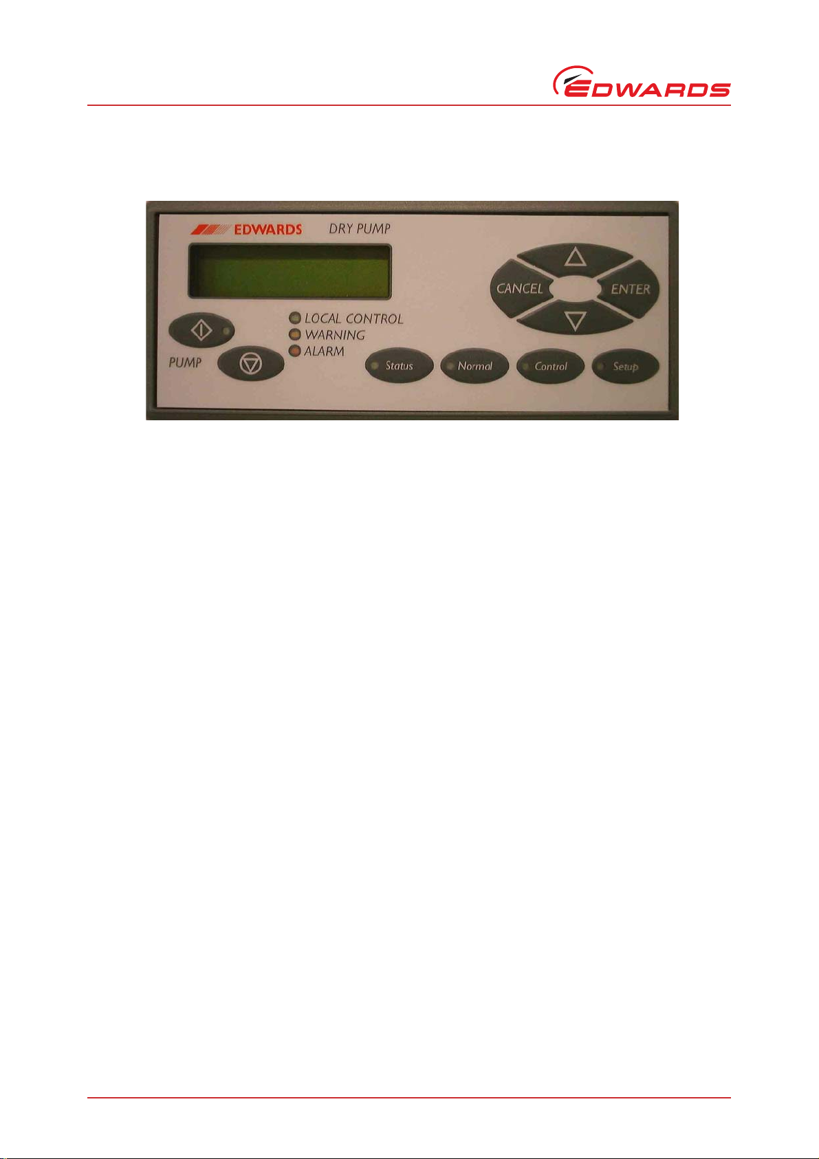
Figure 1 - Front view of the Pump Display Terminal
Page 2 © Edwards Limited 2008. All rights reserved.
Edwards and the Edwards logo are trademarks of Edwards Limited.
Page 7

2Technical data
2.1 Mechanical data
Table 1 - Mechanical data
Dimensions See Figure 2
Maximum mass Approximately 200 g
Figure 2 - Dimensions (mm)
D372-72-880 Issue B
Technical data
© Edwards Limited 2008. All rights reserved. Page 3
Edwards and the Edwards logo are trademarks of Edwards Limited.
Page 8

D372-72-880 Issue B
Technical data
2.2 Electrical connectors
The PDT has a flying lead connection using a coiled cable. When extended, the cable has a nominal length of 1 metre.
The PDT may also be used with a separately supplied extension cable of up to a maximum of 25 m in length. Refer
to Section 7.2 for available cables.
The cable is fitted with a 6 way RJ12 connector, accommodating RS232 transmit and receive and the d.c. power
supply on the following pins:
Table 2 - XLR plug pin descripti ons
Pin number Description Name
1 +ve supply +V d.c. input from host
2 RS232 data TXD input from host
3
†
4
†
5
6 RS232/supply return 0 V input from host
*
Signal naming for pins 2 to 5 follows the DCE convention.
†
Pins 4 and 5 are not connected within the PDT.
RS232 data RXD output to host
Reserved for future use CTS output to host
Reserved for future use RTS input from host
*
Direction
Page 4 © Edwards Limited 2008. All rights reserved.
Edwards and the Edwards logo are trademarks of Edwards Limited.
Page 9

D372-72-880 Issue B
CAUTION
3 Installation
3.1 Unpack and Inspect
Remove all packing materials and check the Pump Displa y Terminal. If the P ump Display Terminal is damaged, notify
your supplier and the carrier in writ ing within three days; state the Item Number of the Pump Display Terminal
together with your order number and your supplier's invoice number. Do not use the Pump Display Terminal if it is
damaged.
If the Pump Di splay Ter minal is n ot to be use d immedia tely, sto re it in su itable co ndition s as desc ribed in Section 6.1.
3.2 Connect the Pump Display Terminal
The PDT connector is intended ONLY for connection to an Edwards pumping system fitted with the appropriate
host port. Edwards and its agents will not be responsible for any damage or loss resulting from connection of the
PDT connector to any socket other than that for which it is intended.
Installation
Fit the PDT connector on the end of the flexible cable to the host port on the dry pumping system.
On initial power-up of the Pump Display Terminal, the indicator LED’s should light briefly, the screen backlight should
illuminate, and the text screen should display the following message:
Display Line 1: Edwards Terminal
Display Line 2: V ersion X. XX (wh ere X.XX is the product version number)
© Edwards Limited 2008. All rights reserved. Page 5
Edwards and the Edwards logo are trademarks of Edwards Limited.
Page 10

D372-72-880 Issue B
This page has been intentionally left blank.
Page 6 © Edwards Limited 2008. All rights reserved.
Edwards and the Edwards logo are trademarks of Edwards Limited.
Page 11

D372-72-880 Issue B
4 Operation of the Pump Display Terminal
The Pump Display Terminal provides monitoring, setup and control of the pump ing system it is connected to.
The pumping system may be started using the Pum p On button ( ) and stopped using the Pump Off button ( ).
Refer to Figure 1.
Other functions are accessed using the four menu buttons:
Status Pumping system status
Normal The main display
Control To take and release control
Setup To change settings on the pumping system
For further detail on the operation of the Pump Display Terminal with your pumping system please refer to the
instruction manual suppli ed wi th t he p um pi n g system.
Operation of the Pump Display Terminal
© Edwards Limited 2008. All rights reserved. Page 7
Edwards and the Edwards logo are trademarks of Edwards Limited.
Page 12

D372-72-880 Issue B
This page has been intentionally left blank.
Page 8 © Edwards Limited 2008. All rights reserved.
Edwards and the Edwards logo are trademarks of Edwards Limited.
Page 13

D372-72-880 Issue B
WARNING
5 Maintenance
5.1 Safety
Obey the safety instructions given below and take note of appropriate precautions. If you do not
you can cause injury to people and damage to equipment.
There are no serviceable parts in the Pump Display Terminal. Do not open the Pump Display Termina l . Retur n the
Pump Display Terminal to your nearest Edwards Service Centre for any repairs that are necessary.
The Edwards return of equipment procedure and forms are included with the Dry Pumping System instruction manuals
and can be down-loaded together with Edwards local contact details from www.edwardsvacuum.com.
5.2 General
z Clean the Pump Display Terminal with a damp cloth. Do not immerse in water, or use solvents.
Maintenance
z Inspect all electrical connections and check that they are secure.
z Inspect all electrical cables and check that they are not damaged and have not overheated.
5.3 Fault finding
Table 3 - Fault finding
Symptom Check/Action
The backlight and indicators do
not illuminate.
The display is showing "Edwards
Terminal connecting ..."
Are the cables too long? Ensure that the communications cables are less than 25 m long. If the
Check that the connector is properly inserted and the host p umping s ystem
power is sw itched on.
The host pumping system is not responding. This may be because of
incorrect connection of the RS232 TX and RX lines. Ensure that the host
system is an Edwards pumping system and that all cables between the Pump
Display Terminal and the host pumping system are genuine Edwards parts.
communications cables are longer than 25 m, ensure that line-drivers are
correctly incorporated into the communications cables.
© Edwards Limited 2008. All rights reserved. Page 9
Edwards and the Edwards logo are trademarks of Edwards Limited.
Page 14

D372-72-880 Issue B
This page has been intentionally left blank.
Page 10 © Edwards Limited 2008. All rights reserved.
Edwards and the Edwards logo are trademarks of Edwards Limited.
Page 15

D372-72-880 Issue B
6 Storage and disposal
6.1 Storage
Store the Pump Display Terminal in clean dry conditions until required. When required for use, install the Pump
Display Termi n al as d e s c ri bed in Section 3 of this manual.
6.2 Disposal
Dispose of the Pump Display Terminal and any components safely in accordance with all local and national safety and
environmental requirements.
Storage and disposal
© Edwards Limited 2008. All rights reserved. Page 11
Edwards and the Edwards logo are trademarks of Edwards Limited.
Page 16

D372-72-880 Issue B
This page has been intentionally left blank.
Page 12 © Edwards Limited 2008. All rights reserved.
Edwards and the Edwards logo are trademarks of Edwards Limited.
Page 17

D372-72-880 Issue B
7 Accessories
7.1 Introduction
Edwards products, spares and acce ssories are available worldwide from Edwards co mpa nie s an d our network of
distributors. Please refer to the back page of this manual or to www.edwardsvacuum.com for contact information.
Order spare parts and accessories from your ne ares t Edwards company or distributor. When you order, plea se st at e
for each part required:
z Model and Item Number of your equipment.
z Serial number (if any).
z Item Number and description of the part.
7.2 Accessories
Accessory Item Number
Accessories
PDT extension cable 3 m D372-72-801
PDT extension cable 5 m D372-72-802
PDT extension cable 10 m D372-72-803
PDT extension cable 15 m D372-72-804
PDT extension cable 25 m D372-72-805
© Edwards Limited 2008. All rights reserved. Page 13
Edwards and the Edwards logo are trademarks of Edwards Limited.
Page 18

D372-72-880 Issue B
This page has been intentionally left blank.
Page 14 © Edwards Limited 2008. All rights reserved.
Edwards and the Edwards logo are trademarks of Edwards Limited.
 Loading...