

Page 1
Instruction Manual
nXDS Serial Comms Interface
A735-01-860
Issue A Original
Description Item Number
nXDS6i A735-01-983
nXDS10i A736-01-983
nXDS15i A737-01-983
nXDS20i A738-01-983
nXDS6iC A735-02-983
nXDS10iC A736-02-983
nXDS15iC A737-02-983
nXDS20iC A738-02-983
nXDS6iR A735-03-983
nXDS10iR A736-03-983
nXDS15iR A737-03-983
nXDS20iR A738-03-983
Page 2

This page has been intentionally left blank.
Page 3

A735-01-860 Issue A
Contents
Section Page
1 Introduction ........................................................................................1
1.1 Scope of this manual.................................................................................................... 1
1.2 Description................................................................................................................ 1
2 Technical data .....................................................................................3
2.1 Logic interface........................................................................................................... 3
3 Connection for serial control and monitoring.................................................5
3.1 Serial connection ........................................................................................................ 5
3.2 Serial enable ............................................................................................................. 6
3.3 Serial protocol ........................................................................................................... 6
3.4 Message structure ....................................................................................................... 7
3.5 Command set............................................................................................................. 7
3.6 Operating the nXDS pump............................................................................................. 12
3.6.1 Start the pump.......................................................................................................... 12
3.6.2 Standby speed........................................................................................................... 12
3.6.3 Stop the pump .......................................................................................................... 12
3.7 Multi-drop operation................................................................................................... 13
3.7.1 Assigning a multi-drop address ....................................................................................... 14
3.8 Mixed parallel and serial operation.................................................................................. 15
3.9 Decoding status words................................................................................................. 16
3.9.1 Decoding system status word......................................................................................... 16
3.9.2 Decoding service status word......................................................................................... 19
Contents
For return of equipment, complete the HS Forms at the end of this manual.
gea/0207/06/12
© Edwards Limited 2012. All rights reserved. Page i
Edwards and the Edwards logo are trademarks of Edwards Limited.
Page 4

A735-01-860 Issue A
Contents
Illustrations
Figure Page
1 Start / Stop Control Diagram ........................................................................................... 1
2 nXDS scroll pump ......................................................................................................... 2
3 Logic interface connections - RS232 serial control.................................................................. 5
4 Logic interface connections - RS485 serial control.................................................................. 6
5 RS485 multi-drop connections.........................................................................................13
6 Logic interface connection - mixed parallel and serial operation ...............................................15
Tables
Table Page
1 Logic interface connection pins........................................................................................ 3
2 Logic interface technical data.......................................................................................... 4
3 Summary of the commands that can be sent to the nXDS pump.................................................. 8
4 Command abbreviations................................................................................................11
5 Error codes ...............................................................................................................11
6 Hexadecimal conversion table.........................................................................................16
7 System status register 1 flags..........................................................................................17
8 System status register 2 flags..........................................................................................17
9 Warning register 2 flags ................................................................................................18
10 Fault register flags ......................................................................................................19
11 Service flags..............................................................................................................20
Associated publications
Publication title Publication number
Vacuum Pump and Vacuum System Safety P400-40-100
nXDS Scroll Pump Instruction Manual A735-01-880
Page ii © Edwards Limited 2012. All ri ghts reserved.
Edwards and the Edwards logo are trademarks of Edwards Limited.
Page 5
A735-01-860 Issue A
1Introduction
1.1 Scope of this manual
This manual provides operational instructions for the Edwards nXDS pump serial communication protocol. Read this
manual before you attempt to operate your nXDS pump using serial communica tion protocol.
For safety and operating information for the nXDS range of pumps, please refer to the nXDS Scroll Pump Instruction
Manual (A735-01-880).
1.2 Description
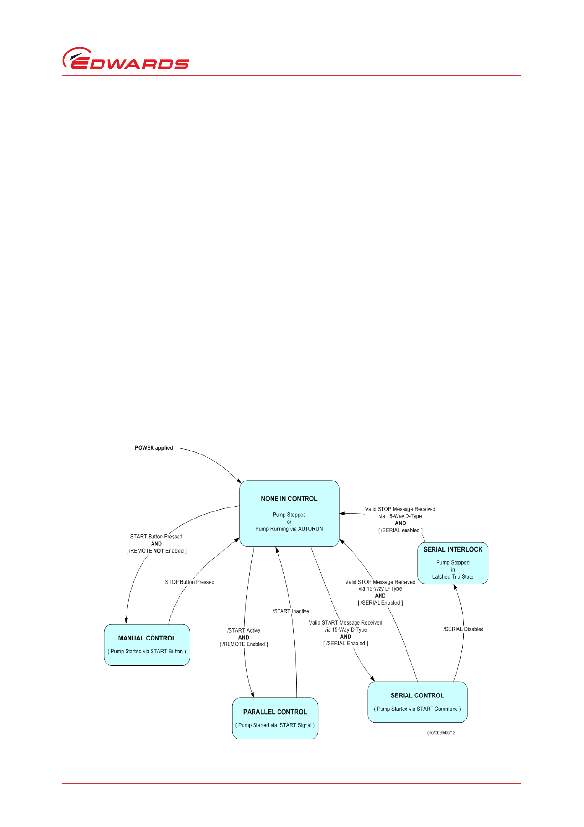
The nXDS pump can be operated in four control modes:
None in Control Mode - Inactive control mode
Manual Control Mode - Active control mode
Parallel Control Mode - Act ive control mode
Introduction
Serial Control Mode (including Serial Interlock) - Active control mode
The control mode is determined by the way the nXDS pump is started. All the control mo des, and transitions between
them, are defined in Figure 1.
Once started the nXDS pump can only be stopped by the mode in which it was started.
Figure 1 - Start / Stop Control Diagram
© Edwards Limited 2012. All rights reserved. Page 1
Edwards and the Edwards logo are trademarks of Edwards Limited.
Page 6
A735-01-860 Issue A
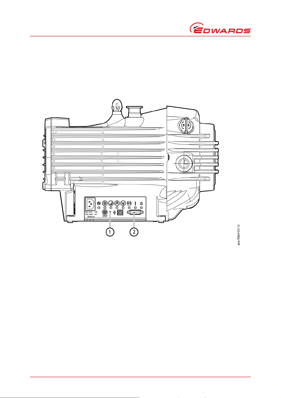
1. User interface panel
2. 15-way logic interface connection
Introduction
This instruction manual details the connection and operation of the nXDS pump in its serial control mode. The
parallel, manual and none in control modes are detailed in the nXDS Scroll Pump Instruction Manual (A735-01-880).
The nXDS pump can be connected directly to the RS485 or RS232 serial input on your control equipment or a PC, using
a suitable connector mating half (not supplied). Full serial control is realised by using the following two signa l lines:
serial enable and RS232 / RS485 control inputs.
Figure 2 - nXDS scroll pump
Page 2 © Edwards Limited 2012. All rights reserved.
Edwards and the Edwards logo are trademarks of Edwards Limited.
Page 7

A735-01-860 Issue A
2Technical data
2.1 Logic interface
nXDS pumps have a male 15-way D-type logic interface connector located on the user interface panel (Figure 2, Item
2). The logic interface connector can be plugged directly into your control equipment or a PC using a suitable
connector mating half (not supplied). Refer to Table 1 for the logic interface pins for the electrical connections and
Table 2 for the interface technical data.
Table 1 - Logic interface connection pins
Pin Number Signal Use
1 Analogue Speed Enable-control Input Connect to Pin 2 (0 V) to enable analogue speed control via
Pin 9.
2 0 V Control Reference 0 V reference for ALL control and status signals listed within
this table.
3 START / STOP – Control Input Connect to Pin 2 (0 V) to START the nXDS pump system.
4STANDBY – Control Input /
RS232 Rx / RS485 A5 Serial Enable – Control Input Connect to Pin 2 (0 V) to enable serial communications.
6 RS232 / RS485 – Control Input Default configuration is RS232 with Pin 6 unconnected.
7 FAIL – Status Output /
RS232 Tx / RS485 B+
8 0 V Control Reference 0 V reference for ALL control and status signals listed within
9 Analogue Speed – Control Input 0-10 V Analogue Input: 0 V = 0% Speed; +10 V = 100% Speed
10 Chassis / Screen Screen
11 +10 V Analogue Reference – Control
Output
12 Chassis / Screen Screen
13 Not Connected Unused control pin.
14 REMOTE – Control Input Connect to Pin 2 (0 V) to enable remote operation via Parallel
15 NORMAL – Status output Logic LOW when the pump rotational speed is at normal
Connect to Pin 2 (0 V) to enable STANDBY speed when the
SERIAL ENABLE control input is inac tive.
Connect to Pin 2 (0 V) to enable RS485 serial
communications.
Logic HIGH when a fail / fault condition exists and the SERI AL
ENABLE control input is inactive.
this table.
+10 V analogue voltage reference output: 5 mA;
uni-polar output, diode protected.
control mode.
speed or above.
Technical data
© Edwards Limited 2012. All rights reserved. Page 3
Edwards and the Edwards logo are trademarks of Edwards Limited.
Page 8

A735-01-860 Issue A
Technical data
Table 2 - Logic interface technical data
Logic interface description
Connector
Start, serial enable and remote enable:
Standby control input:
Analogue and RS485 enable control inputs:
Analogue speed input
Speed set accuracy ± 5% full scale
NORMAL status output:
FAIL status output:
Analogue 10 V reference
Voltage accuracy ± 2%
Output current ≤ 5 mA for specified accuracy
*
Mating half of connector not supplied
*
Enable control voltage: low (closed) 0 to 0.8 V d.c. (l
Disable control voltage: high (open) 4 to 26.4 V d.c. (Internal pull up to 6.4 V nominal)
Enable control voltage: low (closed) 0 to 0.8 V d.c. (l
Disable control voltage: high (open) 4 to 26.4 V d.c. (Internal pull up to 3.2 V nominal)
Enable control voltage: low (closed) 0 to 0.8 V d.c. (l
Disable control voltage: high (open) 4 to 52.8 V d.c. (Internal pull up to 6.4 V nominal)
Type Open collector transistor plus pull up resistor.
< Normal speed (default 80%) OFF (4.7 k pull up + diode to 12 V d.c.)
≥ Normal speed ON (< 0.8 V d.c. sinking 10 mA)
Maximum current rating 10 mA
Maximum voltage rating 28.8 V d.c.
Type Open collector transistor plus pull up resistor.
Fail OFF (4.7 k pull up + diode to 12 V d.c.)
OK ON (< 0.8 V d.c. sinking 10 mA)
Maximum current rating 10 mA
Maximum voltage rating 28.8 V d.c.
15-way D-type (male)
0 to 10 V d.c. directly proportional to the motor speed
e.g. 0 V = 0 Hz, 10 V = 30 Hz
+ 10 V d.c. analogue voltage reference
Unipolar output with diode protection
= 0.55 mA nominal)
OUT
= 0.3 mA nominal)
OUT
= 0.55 mA nominal)
OUT
Page 4 © Edwards Limited 2012. All rights reserved.
Edwards and the Edwards logo are trademarks of Edwards Limited.
Page 9

A735-01-860 Issue A
1. RS232 interface on control equipment or PC
2. nXDS pump logic interface
3 Connection for serial control and
monitoring
The serial interface allows you to control the nXDS pump and to interrogate its operational status using a number of
serial commands. There is also a multi-drop mode that allows you to connect more than one nXDS pump to a single
serial port on your control system.
3.1 Serial connection
The nXDS pump can connect directly to the RS485 or RS232 serial input on your control equipment or a PC as shown
in Figure 3 and 4. In this configuration the PC is the serial link master and the nXDS pump is the slave. The RS232
serial link is capable of operating reliably at distances up to 6m. The RS485 serial link is recommended to maintain
reliable serial communications at distances greater than 6m. Alternatively an interface circuit, external to the nXDS
pump, may be required to communicate using the RS232 serial link over longer distances.
The software in the nXDS pump is capable of operating with several pumps connected to a single serial link master.
This is referred to as multi-drop mode (refer to Section 3.7). The RS485 option is recommended for multi-drop mode.
To enable the RS485 option, link the RS485 input signal to the 0 V Control Reference (pin 6 to pin 2) of your logic
interface mating half.
Connection for serial control and monitoring
Figure 3 - Logic interface connections - RS232 serial control
© Edwards Limited 2012. All rights reserved. Page 5
Edwards and the Edwards logo are trademarks of Edwards Limited.
Page 10

A735-01-860 Issue A
1. RS485 interface on control equipment or PC
2. nXDS pump logic interface
Connection for serial control and monitoring
Figure 4 - Logic interface connections - RS485 serial control
3.2 Serial enable
To send a serial message you mus t first activate serial enab le. This is achieved by linking the serial enable inpu t signal
(pin 5) to pin 2 of your logic interface mating half. We recommend that you incorporate this link into your serial
communications cable so that the serial enable is only activated when the serial cable is connected. When you
subsequently remove the cable, serial enable will become inactive.
Serial enable acts as an interlock for start commands sent over the serial interface. If the nXDS pump is running in
serial control mode (having been sent a serial start command) and the serial enable subsequently becomes inactive,
the nXDS pump will trigger a fail condition and will decelerate to rest. To clear this fail condition, you must reactivate the serial enable and send a serial stop command.
3.3 Serial protocol
The serial interface link is set to 9600 Baud, 8 bits, 1 stop, no parity with no handshaking. The commands are made
up from printable ASCII characters. The maximum message size you can send is 80 characters , including start and end
characters.
All alphabetical characters must be sent in upper case format. Response may contain lower case characters.
Every complete command message you send will receive a response - either a status code or a data return. The n XDS
pump can only deal with one message at a time. It will only accept a new message once the res ponse to the previous
message has been returned.
If the nXDS pump receives characters that are not framed inside start and stop characters, it will ignore them.
Messages with the stop character missing will be discarded with no response when a new start character is received.
If the nXDS pump receives an unrecognisable message between the start and stop characters, it will re turn an
appropriate error message.
Page 6 © Edwards Limited 2012. All rights reserved.
Edwards and the Edwards logo are trademarks of Edwards Limited.
Page 11

A735-01-860 Issue A
3.4 Message structure
The message structure and command set are the same for RS485 and RS232 options. To communicate a message to
the nXDS pump you must send the characters in a specific order. If the message does not conform to the correct
structure it will be ignored and no reply will be sent.
There are two basic types of message sent to the nXDS pump:
A command sending information to the nXDS pump; this is prefixed with a '!' character
A query requesting information from the nXDS pump; this is prefixed with a '?' character
Data is stored and accessed via two memory types within the nXDS Pump:
Non-volatile memory - this provides access to persistent data which is restored after power-cycling; the
prefix 'S' indicates persistent data.
Volatile me mory - this provides access to non-persiste nt data which is NOT restored after power-cycling; the
prefixes 'C' and 'V' indicate non-persistent data.
The correct structure to use is as follows:
a valid start character, either a '!' character for a store operation or a '?' character for a query operation,
followed by
a command, which will be an upper case alphabetical character, followed by
Connection for serial control and monitoring
an object number, comprising three decimal digits, followed by
for some commands only, a data field, comprising a sequence of characters separated from the object
number by a space, followed by
a terminating carriage return, as the stop character
An extended message protocol is used in multi-drop mode, refer to Section 3.7.
3.5 Command set
Table 3 shows a summary of the full set of commands available for controlling and monitoring the nXDS pump.
Table 4 shows the abbreviations that are used to define commands in the following sections and Table 5 shows the
error codes that might be returned.
© Edwards Limited 2012. All rights reserved. Page 7
Edwards and the Edwards logo are trademarks of Edwards Limited.
Page 12

A735-01-860 Issue A
Connection for serial control and monitoring
Table 3 - Summary of the commands that can be sent to the nXDS pump
Object name Command
Identification ?S0 - - - -
Node
Pump type ?S801
Pump control
Speed control !C803
Normal speed
threshold
Standby speed
setting
Auto-run
?S800
!S800
!C802
?V802
?S804
!S804
?S805
!S805
!C805
?S806
!S806
Parameter
range
0..98 0 Decimal
[1..8] - String
[1..11] - String
1..255 - String Hz
0-Decimal-Stop the pump
1 - Decimal Start the pump
0..255 - Decimal Hz Reported motor frequency
64-bits
encoded as
four
16-bit words:
<0000..FFFF>;
<0000..FFFF>;
<0000..FFFF>;
<0000..FFFF>
0-Decimal-Use full speed
1 - Decimal Use standby speed
50..100 80 Decimal %
66..100 70 Decimal %
0
1
Factory
setting
-
0 Decimal -
Data type Units Comments
Hexadeci-
mal
Slave
Address
ASCII
Characters
ASCII
Characters
Acts as wildcard object number to identify
instrument.
Reply identical to ?S801
Multi-drop address (RS485)
0 = disable multi-drop mode;
Pump type (nXDS)
Motor-Control Software
Version number (Dxxxxxxxx Y)
(where Dxxxxxxxx is the
drawing number and Y is the
revision)
Design frequency (= Nominal
mechanical frequency of the
pump)
System status:
System status register 1;
-
System status register 2;
Warning register and Fault
register
Normal speed status output
trigger level:
Percentage (%) of selected
speed
Standby speed of pump:
Percentage (%) of full
mechanical speed (see 801)
!S stores standby speed to
non-volatile memory
(use !C805 for real-time
speed control, faster
execution and extended nonvolatile memory life)
!C retains value in volatile
memory only
Run the nXDS Pump-System
from power-on:
Enable = 1
Disable = 0
*
Page 8 © Edwards Limited 2012. All rights reserved.
Edwards and the Edwards logo are trademarks of Edwards Limited.
Page 13

A735-01-860 Issue A
Table 3 - Summary of the commands that can be sent to the nXDS pump (continued)
Connection for serial control and monitoring
Object name Command
Temperature
readings
Link parameter
readings
Run hours ?V810
Pump cycles ?V811 0..99999 - Decimal Cycles
Drive run time ?V813
Time run since
last tip seal
service
Run time to
tip seal
service
indicator
Service
indicator reset
Time run since
last bearing
service
Run time to
bearing service
indicator
Bearing service
indicator reset
Fault history 1 ?V816
?V808
?V809
?V814
!C814 1 - Decimal -
?V815
!C815 1 - Decimal -
Parameter
range
0..150 - Decimal °C Measured pump temperature
0..150 - Decimal °C
0..5000 - Decimal 0.1V Measured link voltage
±0..300 - Decimal 0.1A Measured motor current
±0..15000 - Decimal 0.1W Measured motor power
0..99999
~11 years
0..99999
~11 years
0..99999
~11 years
0..99999
~11 years
0..99999
~11 years
0..99999
~11 years
0..99999
~11 years
0..99999
64-bits
encoded as
four 16-bit
words:
<0000..FFFF>;
<0000..FFFF>;
<0000..FFFF>;
<0000..FFFF>
Factory
setting
- Decimal Hours
- Decimal Hours
- Decimal Hours
- Decimal Hours
- Decimal Hours
- Decimal Hours
- Decimal Hours
-
Data type Units Comments
Decimal
Hexidecimal
Hours
-
Measured pump-controller
temperature
Total run hours - time pump
has run
Total number of start/stop
cycles
Total run hours - time pumpcontroller has run
Hours until recommended
controller replacement
Number of pump running
hours since last tip seal
service
Number of pump running
hours left until tip seal
service due. Decreases until
due at zero
Command to reset service
indicators, 'time since' to
zero and 'time to' to service
interval
Number of pump running
hours since last bearing
service
Number of pump running
hours left until bearing
service due. Decreases until
due at zero
Command to reset service
indicators, 'time since' to
zero and 'time to' to service
interval
Fault history at last trip:
nXDS pump-controller
powered time (hours)
system status register 01;
system status register 02;
warning register 01 and fault
register 01
†
*
†
© Edwards Limited 2012. All rights reserved. Page 9
Edwards and the Edwards logo are trademarks of Edwards Limited.
Page 14

A735-01-860 Issue A
Connection for serial control and monitoring
Table 3 - Summary of the commands that can be sent to the nXDS pump (continued)
Object name Command
Fault history 2 ?V817
Fault history 3 ?V818
Fault history 4 ?V819
Customer
interface
software version
Factory
settings
Motor-control
boot-loader
version
Customer
interface
boot-loader
version
?S820 [1..11] - String
!C821 1 - Decimal -
?S822 [1..11] - String
?S823 1..11] - String
Parameter
range
0..99999
64-bits
encoded as
four 16-bit
words:
<0000..FFFF>;
<0000..FFFF>;
<0000..FFFF>;
<0000..FFFF>
0..99999
64-bits
encoded as
four 16-bit
words:
<0000..FFFF>;
<0000..FFFF>;
<0000..FFFF>;
<0000..FFFF>
0..99999
64-bits
encoded as
four 16-bit
words:
<0000..FFFF>;
<0000..FFFF>;
<0000..FFFF>;
<0000..FFFF>
Factory
setting
-
-
-
Data type Units Comments
Fault history at 2nd last trip:
Decimal
Hexidecimal
Decimal
Hexidecimal
Decimal
Hexidecimal
Hours
-
Hours
-
Hours
-
ASCII
Characters
ASCII
Characters
ASCII
Characters
nXDS pump-controller
powered time (hours)
system status register 01;
system status register 02;
warning register 01 and fault
register 01
Fault history at 3rd last trip:
nXDS pump-controller
powered time (hours)
system status register 01;
system status register 02;
warning register 01 and fault
register 01
Fault history at 4th last trip:
nXDS pump-controller
powered time (hours)
system status register 01;
system status register 02;
warning register 01 and fault
register 01
Customer interface software
version number (Dxxxxxxxx Y)
(where Dxxxxxxxx is the
drawing number and Y is the
revision)
Reset all configuration
options and parameters to
factory settings
Motor-control boot-loader
version number
(Dxxxxxxxx Y)
(where Dxxxxxxxx is the
drawing number and Y is the
revision)
Customer interface bootloader version number
(Dxxxxxxxx Y)
(where Dxxxxxxxx is the
drawing number and
Y is the revision)
*
*
*
Page 10 © Edwards Limited 2012. All rights reserved.
Edwards and the Edwards logo are trademarks of Edwards Limited.
Page 15

A735-01-860 Issue A
Table 3 - Summary of the commands that can be sent to the nXDS pump (continued)
Connection for serial control and monitoring
Object name Command
Service setting
Service status ?V826
Service ?S835
*
See Section 3.9.1 for status word decoding
†
If either returned value is ‘-200’, then this means that this temperature is not utilised within the product
‡
See Section 3.9.2 for service word decoding
!S825
?S825
Parameter
range
0..3 0 Decimal -
One 16-bit
word:
<0000..FFFF>
[1..30] - String
[1..36] - String
Table 4 - Command abbreviations
Factory
setting
- Hexidecimal -
Data type Units Comments
ASCII
Characters
ASCII
Characters
0: Service indication on
Service LED
1: Service indication on
Service LED and FAIL line
2: No service indication on
Service LED or FAIL line
3: Service indication on FAIL
line
Service status word –
Contact Edwards for more
information
Serial numbers:
pump; drive-module and
power/control PCA
(fixed at manufacture, 9
characters each)
Pump type and build
‡
Abbreviation Meaning
cr carriage return character
chars characters
d decimal ASCII character
Note: Fields showing multiple d characters are to indicate typical length. All
h hexadecimal ASCII character
r Returned error code - refer to Table 5
sp space character
string may have several ASCII characters
X Multi-drop decimal ASCII character
Note: Fields showing multiple X characters are to indicate maximum length and
Returned error code Meaning
0 No error
1 Invalid command for object ID
2 Invalid Query/Command
3Missing parameter
4 Parameter out of range
5 Invalid command in current state - e.g. serial command to start/stop when in par-
allel control mode
data fields have a maximum of 5 decimal characters (prefixed by a minus
number for negative numbers).
not fixed length.
Table 5 - Error codes
© Edwards Limited 2012. All rights reserved. Page 11
Edwards and the Edwards logo are trademarks of Edwards Limited.
Page 16

A735-01-860 Issue A
Connection for serial control and monitoring
3.6 Operating the nXDS pump
3.6.1 Start the pump
To start the pump, send the following command over the serial communications link:
Command ! C 8 0 2sp1cr
The reply you receive will be in the following format:
Reply *
The pump will then accelerate up to the target speed and the green run LED will flash whilst it is doing so. When the
pump reaches its target speed, the green run LED will remain illuminated.
C 8 0 2sp rcr
3.6.2 Standby speed
To run the nXDS pump at standby speed, send the following command over the serial communications link:
Command !
The reply you receive will be as follows:
Reply * C 8 0 3sp rcr
If the pump is currently below standby speed then it will accelerate until it reaches s tandby speed. If it is running
faster than standby speed, it will decelerate until standby speed is reached.
To return the pump to full speed, send the following command:
Command ! C 8 0 3sp0cr
The reply you receive will be as follows:
Reply *
C 8 0 3sp1cr
C 8 0 3sp rcr
3.6.3 Stop the pump
To stop the nXDS pump, send the following command over the serial communications link:
Command !
The reply you receive will be in the following format:
Reply * C 8 0 2sp rcr
On successful receipt of the stop command, the pump will decelerate to rest.
Page 12 © Edwards Limited 2012. All rights reserved.
C 8 0 2sp0cr
Edwards and the Edwards logo are trademarks of Edwards Limited.
Page 17

A735-01-860 Issue A
1. RS485 interface on control equipment or PC
2. nXDS pump logic interface
3.7 Multi-drop operation
Using multi-drop mode, a single computer system can communicate with more than one nXDS pump. Each nXDS pump
must be assigned its own individual address, or node, before it can be fitted into a multi-drop system. The command
to assign the multi-drop addres s is sent in standard nXDS message format and is detailed in Section 3.7.1 below.
The message protocol in multi-drop mode is marginally different to that des cribed for serial messages in single pump
systems (Section 3.4). The main differences in multi-drop message protocol are detailed below:
All multi-drop commands, queries or replies have the start character #.
All multi-drop commands, queries and replies include a header, which contains the address of the node that
the message is to, followed by the address of the node that the message is from.
There is a delimiter character ':' (colon) which separates the two multi-drop addresses in the header.
The remainder of the message (command, query or reply) follows the same protocol as already de scribed for
single pump systems.
The wild card address 99 means 'any' node.
After a nXDS pump has been assigned a multi-drop address, it w ill ignore any messages in the format for single pumps.
An individual nXDS pump will remain silent and ignore all command messages unless the multi-drop address matches
its own address.
Connection for serial control and monitoring
Figure 5 shows a schematic diagram of an example multi-drop connection system, which can be expanded to
accommodate multiple pumps.
Figure 5 - RS485 multi-drop connections
© Edwards Limited 2012. All rights reserved. Page 13
Edwards and the Edwards logo are trademarks of Edwards Limited.
Page 18

A735-01-860 Issue A
Connection for serial control and monitoring
3.7.1 Assigning a multi-drop address
When you receive your nXDS pump it will have multi-drop mode disabled by default. Each individual pump must be
programmed with its own multi-drop address, via a point-to-point connection, before introduction into a multi-drop
network.
Send the following command to assign a multi-drop address (where the 'd' characters represent the address):
Command ! S
Note: The address can be any decimal number from 1 to 98. The address number 0 is used to disable multi-drop
mode. The address number 99 is reserved as a wild card and is used in the query set up detailed later.
The reply you receive will be as follows:
Reply * S 8 0 0sprcr
The multi-drop address is stored within the nXDS pump.
You can also send a query to the pump to find out whether it already has a multi-drop address. Send the following
command:
Reply ? S
If you receive the reply shown below, your pump has mu lti-drop mode disabled:
Reply = S
If your pump already has a multi-drop address you will receive no reply and you must then communicate with your
pump in multi-drop message protocol.
Use the following query (using wild card address 99 which means ‘any’ node) to find out the multi-drop ad dress of
the nXDS pump:
Command # 9 9:9 9? S8 0 0cr
8 0 0spd dcr
8 0 0cr
8 0 0sp0cr
The reply you receive will be as follows, where dd denotes the multi-drop address of the pump:
Reply #
You can disable multi-drop mode by assigning the pump an address 0. To do this, send the following command (where
dd denotes the multi-drop address of the pump and xx denotes the address of the node that is sending the command):
Command #
The reply you receive will be as follows:
Reply #
Once multi-drop mode is disabled, the pump will no longer respond to multi-drop commands.
9 9:9 9= S8 0 0spd dcr
d d:x x! S8 0 0sp0cr
x x:d d* S8 0 0sp0cr
Page 14 © Edwards Limited 2012. All rights reserved.
Edwards and the Edwards logo are trademarks of Edwards Limited.
Page 19

A735-01-860 Issue A
1. RS232 interface on control equipment or PC
2. nXDS pump logic interface
3. Start / Stop switch
4. Optional LED indicator - normal speed
5. Current limit resistor for LED
3.8 Mixed parallel and serial operation
You can control the nXDS pump using the parallel interface control inputs and at the same time monitor various pump
parameters using the serial interface. Alternatively you can control the nXDS pump using commands sent over the
serial interface and at the same time monitor the normal signal using the parallel interface. Figure 6 shows a
schematic diagram of an example mixed operation system that would allow you to do this. Many of the individual
functions available in either parallel or serial operations are also available in mixed parallel and serial operation; but
note that whilst serial enable is active, the parallel standby and fail signals are not available.
The following functions can also be used in conjunction with mixed parallel and serial operation:
Multi-drop operation; described in Section 3.7.
Analogue speed control; described in the nXDS Scroll Pump Instruction Manual (A735-01-880)
For more information on the parallel control and monitoring, please refer to the nXDS Scroll Pump Instruction Manual
(A735-01-880).
Figure 6 - Logic interface connection - mixed parallel and serial operation
Connection for serial control and monitoring
You cannot control the nXDS pump using both the parallel and serial interfaces simultaneously. For example, if you
start the pump by sending a start command over the serial interface, you cannot then stop the pump by using the
parallel interface; you must stop the pump by sending a stop command over the serial interface. Similarly, if you
start the pump by using the start / stop switch on the parallel interface, you cannot then stop the pump by using the
serial interface; you must stop the pump by using the start / stop switch on the parallel interface.
© Edwards Limited 2012. All rights reserved. Page 15
Edwards and the Edwards logo are trademarks of Edwards Limited.
Page 20

A735-01-860 Issue A
Connection for serial control and monitoring
3.9 Decoding sta tus words
3.9.1 Decoding system status word
If you are using the serial communications link you will be able to access further information that may be useful for
fault finding. When you send a query to monitor measured motor speed, the pump also returns a s ystem status wo rd.
The send command is as follows:
Command ?
You will receive the following reply, where the first returned number refers to motor rotational speed in revolutions
per second (Hz):
Reply =
The system status word returned is made up of 4 separate status words, each made up of 4 hexadecimal digits and
are separated by a semi-colon ';'. The first status word is 'System status register 1', then 'System status register 2',
then 'Warning register' and the final status word is 'Fault register'. To decode each indivi dua l status w ord, you mu st
convert each hexadecimal digit into a 4-digit binary number. (Table 6 is provided as an aid.) Follow the example
below:
V 8 0 2spd d d;h h h h;h h h h;h h h h;h h h hcr
2283
0010001010000011
Table 6 - Hexadecimal conversion table
Hexadecimal Binary Decimal
000000
100011
200102
300113
401004
501015
601106
701117
810008
910019
A101010
B101111
C110012
D110113
E111014
F111115
V 8 0 2cr
Page 16 © Edwards Limited 2012. All rights reserved.
Edwards and the Edwards logo are trademarks of Edwards Limited.
Page 21

A735-01-860 Issue A
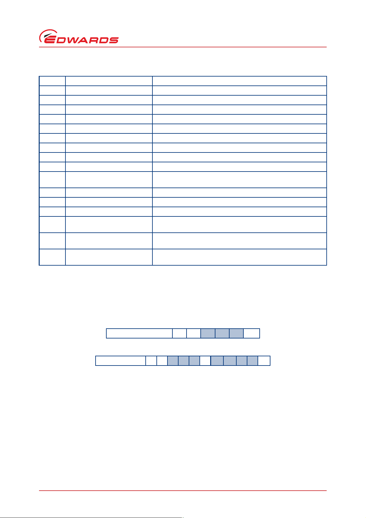
Each binary digit (bit) represents a flag that is either active (state 1) or not active (state 0). To help decode each of
the system status words, each bit is numbered (starting with 0 for the least significant to 15 for the most significant),
as shown below:
0000000000100010
Connection for serial control and monitoring
15141312111
The following 4 tables each contain a list of the 16 status flags that will be used for decoding the status or fault
finding for the nXDS pump. Table 7 contains the 16 flags used to decode the 'System status register 1', Table 8
contains the 16 flags used to decode the 'System status register 2', Table 9 contains the 16 flags used to decode the
'Warning register' and Table 10 contains the 16 flags used to decode the 'Fault register'.
Table 7 - System status register 1 flags
Bit Status Flag Active Flat Meas
0 (lsb) Deceleration Stop command received and pump-controller is in the de celeration/
1 Acceleration/running Accelerating or running
2 Standby speed Standby active
3 Normal speed Above normal speed
4 Above ramp speed Operating above the ramp speed threshold
5 Above overload speed Operating above the overload speed threshold
6 Control mode Bits 6, 7 and 13 indicate which control mode the pump-controller is
7
8Reserved-
9Reserved10 Serial enable Serial enable active
11 Reserved 12 Reserved 13 Control mode Used in conjunction with bits 6 and 7 above
14 Reserved -
15 (msb) Reserved -
System status regis
Table 8 - System status register 2 flags
9876543210
0
ramp down process
operating in (bit 13; bit 7; bit 6).
000=none; 001=serial; 010=parallel; 011=manual
100...111=reserved
Bit Status Flag Active Flat Meas
0 (lsb) Upper power regulator active Power limit is active - i.e. pump operating on power limit
1 Lower power regulator active Acceleration is limited to manage link voltage
2 Upper voltage regulator active Deceleration is limited to manage link voltage
3Reserved-
4 Service due Service is due - See hours counters to identify what needs replacing
or use command ?V826
5Reserved6 Warning Warning condition - See 'Warning register' for detail
7 Alarm Fault condition - See 'Fault register' for detail
© Edwards Limited 2012. All rights reserved. Page 17
Edwards and the Edwards logo are trademarks of Edwards Limited.
Page 22

A735-01-860 Issue A
Connection for serial control and monitoring
Table 8 - System status register 2 flags (continued)
Bit Status Flag Active Flat Meas
8Reserved9Reserved-
10 Reserved 11 Reserved 12 Reserved 13 Reserved 14 Reserved -
15 (msb) Reserved -
Table 9 - Warning register 2 flags
Bit Status Flag Active Flat Meas
0 (lsb) Reserved -
1 Low pump-controller
temperature
2Reserved3Reserved4Reserved5Reserved6 Pump-controller temperature
regulator active
7Reserved8Reserved9Reserved-
10 High pump-controller
temperature
11 Reserved 12 Reserved 13 Reserved 14 Reserved -
15 (msb) Self test warning Non-critical problem with EEPROM or other internal function
Pump-controller temperature is below the minimum measurable
value
Output current is being restricted due to high pump-controller
temperature
Pump-controller temperature is above the maximum measurable
value
Page 18 © Edwards Limited 2012. All rights reserved.
Edwards and the Edwards logo are trademarks of Edwards Limited.
Page 23
A735-01-860 Issue A
Table 10 - Fault register flags
Bit Status Flag Active Flat Meas
0 (lsb) Reserved -
1 Over voltage trip Fault due to excessive link voltage
2 Over current trip Fault due to excessive motor current
3 Over temperature trip Fault due to excessive pump-controller temperature
4 Under temperature trip Pump-controller temperature sensor failure
5 Power stage fault Power stage failure
6Reserved7Reserved8 H/W fault latch set Hardware fault latch active, see bits 0-7 for detail
9 EEPROM fault Fault due to a critical EEPROM problem (e.g. Parameter upload
incomplete)
10 Reserved 11 No parameter set Parameter set upload required
12 Self test fault Self test fault (e.g. Invalid software code)
13 Serial control mode interlock Fault because the serial enable input went inactive whilst operating
with a serial start command
14 Overload time out Fault because the output frequency fell below the threshold for
more than the allowable time (with an active start command)
15 (msb) Acceleration time out Fault because the output frequency did not reach the threshold in
the allowable time (following a start command)
Connection for serial control and monitoring
3.9.2 Decoding service status word
The service status may be accessed directly via the seri al link. Thi s method of acces sin g service s tatu s will give the
most complete picture of current and future service requirements and will allow preventative maintenance activities
to be scheduled.
A summary of the current pending service status is provided in response to the service status command:
Command ?
You will receive the following reply:
Reply = V
The service status word is made up of 4 hexadecimal digits. To decode this word, you must convert each hexadecimal
digit into a 4-digit binary number as described in Section 3.9.1.
Each binary digit (bit) represents a flag that is either active (state 1) or not active (state 0). To help decode the
service status word, each bit is numbered (starting with 0 for the least significant to 15 for the most significant) as
shown in Section 3.9.1. The meaning of each bit in the service status word is given in Table 11.
8 2 6sph h h hcr
V 8 2 6cr
© Edwards Limited 2012. All rights reserved. Page 19
Edwards and the Edwards logo are trademarks of Edwards Limited.
Page 24

A735-01-860 Issue A
Connection for serial control and monitoring
Table 11 - Service flags
Bit number Status flag Active flag means
0 Tip seal service due Set when hours until tip seal service due = 0
1 Bearing service due Set when hours until bearing service due = 0
2Reserved -
3 Controller service due Set when hours until controller service due = 0
4Reserved -
5Reserved -
6Reserved -
7 Service due Service is due. Specific operation required should be
determined by checking the bits above
8 - 15 Reserved -
Page 20 © Edwards Limited 2012. All rights reserved.
Edwards and the Edwards logo are trademarks of Edwards Limited.
 Loading...