

Page 1
Instruction Manual
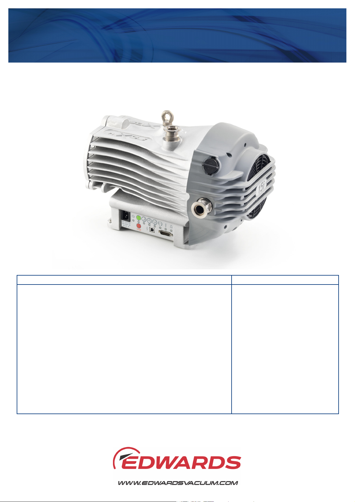
nXDS Scroll Pump
A735-01-880
Issue F
Description Item Number
nXDS6i A735-01-983
nXDS10i A736-01-983
nXDS15i A737-01-983
nXDS20i A738-01-983
nXDS6iC A735-02-983
nXDS10iC A736-02-983
nXDS15iC A737-02-983
nXDS20iC A738-02-983
nXDS6iR A735-03-983
nXDS10iR A736-03-983
nXDS15iR A737-03-983
nXDS20iR A738-03-983
Original Instructions
Page 2

This product has been manufactured under a quality management system certified to ISO 9001:2015.
P200-06-720-F
2006/42/EC
Machinery directive
2014/35/EU
Low voltage directive
2014/30/EU
Electromagnetic compatibility (EMC) directive
2014/34/EU
ATEX directive on use in potentially explosive atmospheres
II 3 G Ex h IIB T4 Gc Internal Atmospheres Only, Tech File ref 209
2011/65/EU
Restriction of certain hazardous substances (RoHS) directive
EN 1012-2:1996
+A1:2009
Compressors and vacuum pumps. Safety requirements. Vacuum pumps
BS EN ISO 8007936:2016
Non-electrical equipment for explosive atmospheres. Basic method and requirement
BS EN ISO 8007937:2016
Non-electrical equipment for explosive atmospheres. Non-electrical type of
constructional safety ‘c’
EN 61010-1:2010
Safety requirements for electrical equipment for measurement, control and
laboratory use. General requirements
EN 61326-1:2013
Electrical equipment for measurement, control and laboratory use. EMC
Class A Emissions, Industrial Immunity
CSA-C22.2
No.61010-1-12
Safety requirements for electrical equipment for measurement, control and
laboratory use – Part 1: General requirements
UL61010-1
3rd Edition
Safety requirements for electrical equipment for measurement, control and
laboratory use – Part 1: General requirements
Mr Ian Keech
Date and Place
Declaration of Conformity
Edwards Ltd,
Innovation Drive,
Burgess Hill,
West Sussex, RH15 9TW, UK
The following products:
nXDS6i scroll pump 100-127/200-240V, 50/60Hz A735-01-983
nXDS10i scroll pump 100-127/200-240V, 50/60Hz A736-01-983
nXDS15i scroll pump 100-127/200-240V, 50/60Hz A737-01-983
nXDS20i scroll pump 100-127/200-240V, 50/60Hz A738-01-983
nXDS6iC scroll pump 100-127/200-240V, 50/60Hz A735-02-983
nXDS10iC scroll pump 100-127/200-240V, 50/60Hz A736-02-983
nXDS15iC scroll pump 100-127/200-240V, 50/60Hz A737-02-983
nXDS20iC scroll pump 100-127/200-240V, 50/60Hz A738-02-983
nXDS6iR scroll pump 100-127/200-240V, 50/60Hz A735-03-983
nXDS10iR scroll pump 100-127/200-240V, 50/60Hz A736-03-983
nXDS15iR scroll pump 100-127/200-240V, 50/60Hz A737-03-983
nXDS20iR scroll pump 100-127/200-240V, 50/60Hz A738-03-983
Is in conformity with the relevant requirements of European CE legislation:
Based on the relevant requirements of harmonised standards:
requirements. General requirements
The product also complies with the following:
This covers all product serial numbers from the date of this declaration onwards.
19.10.2018, Burgess Hill
Vice President Engineering, High Vacuum Division
This declaration is based on the requirements of EN ISO 17050-1 and the relevant directives.
Page 3
P200-10-019
Issue D
Material Declaration
In accordance with the requirements of the Chinese regulatory requirement on the Ma nagement Methods for the
Restriction of the Use of Hazardous Substances in Electrical and Electronic Products Order No. 32 (also known as
‘China RoHS2’) and SJ/T 11364 Marking for the Restricted Use of Hazardous Substances in Electronic and Electrical
Products:
Product Labels
Product Product Label Meaning
This product contains hazardous substances in at least one of the
All pumps in the
list below
Pump Type Pump Size
RV Pumps RV3,5,8,12, E Lab, nRVi
EM Small Pumps E2M0.7, 1.5, E1M18, E2M18, 28, 30, nE2M40i
nEXT Pumps nEXT 85, 240, 300, 400, Splitflow
nXDS pumps nXDS 6, 10, 15, 20
EXT pumps EXT75DX
XDS pumps XDS35, 46, 100
Diaphragm XDD 1, D lab
Turbo Pump Carts T station, nEXPT, nEXT station
部件名称
Part name
铸铝
Cast Aluminium
铜管管件
Brass pipe Fittings
铜接头
Brass Connectors
2020
铅
Lead
(Pb)
Mercury
X O O O O O
X O O O O O
X O O O O O
homogeneous materials used which are above the limit requirement
in GB/T 26572 as detailed in the declaration table below.
These parts can safely be used for the environmental protection use
period as indicated.
材料成分声明
Materials Content Declaration
质
汞
(Hg)
镉
Cadmium
(Cd)
危险物
六价铬
Hexavalent
Chromium
(Cr VI)
多溴联苯
Polybrominated
biphenyls (PBB)
Polybrominated
diphenyl ethers
多溴二苯醚
(PBDE)
O: 表示该有害物质在该部件的所有均质材料中的含量低于 GB/T 26572 标准规定的限量要求。
O: Indicates that the hazardous substance contained in all of the homogeneous materials for this part is below
the limit requirement in GB/T 26572.
X: 表示该有害物质在该部件的至少一种均质材料中的含量超出 GB/T26572 标准规定的限量要求。
X: Indicates that the hazardous substance contained in at least one of the homogeneous materials used for
this part is above the limit requirement of GB/T26572.
NOTES: These products are EU RoHS compliant, the following Exemptions apply:
6(b) Lead as an alloying element in aluminium containing up to 0.4% by weight.
6(c) Copper alloy containing up to 4% lead by weight
Packaging Information
Pallet Over-shipper Protection Pieces Support Braces
NWNW
Recyclable Natural Wood Recyclable Cardboard Recyclable Polypropylene Recyclable Mild Steel
Page 4

This page has been intentionally left blank.
Page 5

A735-01-880 Issue F
Contents
Section Page
1 Introduction ........................................................................................ 1
1.1 Scope of this manual .................................................................................................... 1
1.2 ATEX directive implication ............................................................................................. 2
1.3 General description ..................................................................................................... 2
1.4 Pump controller.......................................................................................................... 3
1.5 Logic interface ........................................................................................................... 4
1.6 Gas ballast control ...................................................................................................... 4
2 Technical data ..................................................................................... 7
2.1 Operating and storage conditions ..................................................................................... 7
2.2 Performance.............................................................................................................. 7
2.2.1 General.................................................................................................................... 7
2.2.2 Pumping media........................................................................................................... 8
2.2.3 Performance characteristics ........................................................................................... 8
2.3 Mechanical data ........................................................................................................ 11
2.3.1 General................................................................................................................... 11
2.3.2 Sound and vibration data.............................................................................................. 11
2.3.3 Construction............................................................................................................. 11
2.4 Electrical data .......................................................................................................... 11
2.4.1 Electrical cables ........................................................................................................ 12
2.5 Logic interface data.................................................................................................... 12
2.6 LED indicators ........................................................................................................... 14
Contents
3 Installation ....................................................................................... 15
3.1 Safety..................................................................................................................... 15
3.2 System design considerations......................................................................................... 15
3.3 Unpack and inspect .................................................................................................... 17
3.4 Position the pump ...................................................................................................... 17
3.4.1 Mechanical fixing ....................................................................................................... 17
3.5 Connect to the vacuum system....................................................................................... 17
3.6 Electrical installation .................................................................................................. 18
3.6.1 Fuses and circuit breakers ............................................................................................ 18
3.6.2 Electrical supply connection .......................................................................................... 19
3.6.3 Disconnect the pump from the electrical supply .................................................................. 19
3.7 Connection for remote control and monitoring.................................................................... 19
3.7.1 Connect the logic interface to the control equipment ........................................................... 19
4 Operation ......................................................................................... 21
4.1 Operational modes ..................................................................................................... 21
4.2 Manual operation ....................................................................................................... 21
4.2.1 Start and stop ........................................................................................................... 22
4.2.2 Standby................................................................................................................... 22
4.3 Parallel control and monitoring ...................................................................................... 23
4.4 Analogue speed control................................................................................................ 24
4.4.1 Hardware configuration ............................................................................................... 25
4.4.2 Operation ................................................................................................................ 25
4.5 Auto-run.................................................................................................................. 26
4.6 Use of gas ballast control ............................................................................................. 26
4.6.1 Gas ballast control ..................................................................................................... 26
4.7 Start up procedure ..................................................................................................... 26
4.8 To achieve ultimate vacuum.......................................................................................... 27
gp/0281/01/18
4.9 To pump condensable vapours ....................................................................................... 27
© Edwards Limited 2018. All rights reserved. Page i
Page 6

A735-01-880 Issue F
Contents
4.10 Shut down................................................................................................................ 27
5 Maintenance...................................................................................... 29
5.1 Safety information...................................................................................................... 29
5.2 Maintenance plan....................................................................................................... 30
5.3 Inspect and clean the inlet strainer ................................................................................. 30
5.4 Clean the external fan cover ......................................................................................... 30
5.5 Check the pump performance (service indicator) ................................................................. 30
5.6 Replace the tip-seals................................................................................................... 31
5.7 Replace the pump bearings (service indicator) .................................................................... 31
5.8 Replace the pump controller (service indicator) .................................................................. 31
5.9 Electrical safety check................................................................................................. 31
5.10 Service indicator codes ................................................................................................ 32
5.11 Fault finding............................................................................................................. 32
5.11.1 The pump has failed to start or has stopped ....................................................................... 32
5.11.2 The pump has failed to achieve the required performance ..................................................... 32
5.11.3 The pump has poor ultimate vacuum................................................................................ 33
5.11.4 The pump is noisy ...................................................................................................... 33
5.11.5 The pump surface temperature is high ............................................................................. 33
5.11.6 Alarm indicator codes.................................................................................................. 34
6 Storage and disposal ............................................................................ 37
6.1 Storage ................................................................................................................... 37
6.2 Disposal .................................................................................................................. 37
7 Spares and accessories ......................................................................... 39
7.1 Introduction ............................................................................................................. 39
7.2 Accessories .............................................................................................................. 40
7.2.1 Silencer................................................................................................................... 41
7.2.2 Gas ballast adaptor..................................................................................................... 41
7.2.3 Gas ballast adaptor blank ............................................................................................. 41
7.2.4 Vibration isolators ...................................................................................................... 41
7.2.5 Inlet/exhaust filter..................................................................................................... 41
7.2.6 Exhaust nozzle .......................................................................................................... 42
7.2.7 Chemical resistance conversion kit .................................................................................. 42
7.2.8 Electrical cables ........................................................................................................ 42
7.2.9 Pump-to-controller cable ............................................................................................. 42
7.3 Spares .................................................................................................................... 43
7.3.1 Tip-seal kit (Youtube video https://www.youtube.com/watch?v=vKnh9dxOyhE) ........................... 43
7.3.2 Cooling fan............................................................................................................... 43
7.3.3 Gas ballast knob ........................................................................................................ 43
7.3.4 Silencer spares kit ...................................................................................................... 43
7.3.5 Inlet/exhaust filter spares ............................................................................................ 43
7.3.6 Bearing replacement kit (not field serviceable) ................................................................... 44
7.3.7 Exhaust and ballast valve kit ......................................................................................... 44
For return of equipment, complete the HS Forms at the end of this manual.
Page ii © Edwards Limited 2018. All rights reserved.
Page 7

A735-01-880 Issue F
Illustrations
Figure Page
1 nXDS scroll pump ......................................................................................................... 3
2 Quick start guide (manual control mode)............................................................................. 5
3 nXDS6i Performance characteristics ................................................................................... 9
4 nXDS10i Performance characteristics ................................................................................. 9
5 nXDS15i Performance characteristics ................................................................................ 10
6 nXDS20i Performance characteristics ................................................................................ 10
7 LED indicators ............................................................................................................ 14
8 Installation drawing ..................................................................................................... 16
9 User interface panel ....................................................................................................22
10 Logic interface connections - parallel control ......................................................................23
11 Logic interface connections - analogue speed control............................................................. 24
12 Analogue speed control................................................................................................. 25
13 Poor ultimate vacuum flow chart .....................................................................................33
14 Noisy pump flow chart .................................................................................................. 34
15 nXDS accessories.........................................................................................................40
Contents
Tables
Table Page
1 nXDS Control modes...................................................................................................... 6
2 Operating and storage conditions ...................................................................................... 7
3 Environmental conditions ............................................................................................... 7
4 General characteristics .................................................................................................. 7
5 Performance characteristics ............................................................................................ 8
6 General mechanical data............................................................................................... 11
7 Sound and vibration data...............................................................................................11
8 Electrical ratings for continuous operation.......................................................................... 11
9 Recommended regional supply protection...........................................................................11
10 Recommended cord sets................................................................................................12
11 Logic interface technical data......................................................................................... 12
12 Logic interface connector pins ........................................................................................13
13 LED indicators ............................................................................................................ 14
14 Maintenance plan........................................................................................................30
15 Flashing service codes ..................................................................................................32
16 Flashing error codes..................................................................................................... 35
17 Silencer....................................................................................................................41
18 Gas ballast adaptor...................................................................................................... 41
19 Gas ballast blank adaptor ..............................................................................................41
20 Vibration isolators .......................................................................................................41
21 Inlet/exhaust filter......................................................................................................41
22 Exhaust nozzle ...........................................................................................................42
23 Chemical resistance conversion kit ...................................................................................42
24 Electrical cables .........................................................................................................42
25 Pump-to-controller cables .............................................................................................42
26 Tip-seal kit................................................................................................................43
27 Cooling fan................................................................................................................43
28 Gas ballast knob .........................................................................................................43
© Edwards Limited 2018. All rights reserved. Page iii
Page 8

A735-01-880 Issue F
Contents
29 Silencer spares kit .......................................................................................................43
30 Inlet/exhaust filter spares .............................................................................................43
31 Bearing replacement kit................................................................................................44
32 Exhaust and ballast valve kit ..........................................................................................44
Associated publications
Publication title Publication number
Vacuum Pump and Vacuum System Safety P400-40-100
nXDS Serial Comms Interface Instruction Manual A735-01-860
Trademark credits
Edwards and the Edwards logo are trademarks of Edwards Limited, Innovation Drive, Burgess Hill,
West Sussex, RH15 9TW, UK.
Page iv © Edwards Limited 2018. All rights reserved.
Page 9
A735-01-880 Issue F
CAUTION
WARNING
1Introduction
1.1 Scope of this manual
This manual provides installation, operation and maintenance instructions for the Edwards nXDS series of scroll
pump. The pump must be used as specified in this manual or the protection provided by the equipment may be
impaired. Read this manual before installing and operating the pump.
Important safety information is highlighted as WARNING and CAUTION instructions; these instructions must be
obeyed. The use of WARNINGS and CAUTIONS is defined below.
Warnings are given where failure to observe the instruction could result in injury or death to
people. The actual symbol shown varies according to the hazard.
Cautions are given where failure to observe the instruction could result in damage to the equipment, associated
equipment and process.
Introduction
Pressures are stated as absolute pressures unless otherwise stated.
The units used throughout this manual conform to the SI international system of units of measurement. The following
warning labels may be present on the pump and used throughout the product documentation.
Warning – an appropriate safety instruction should be followed or a caution to a potential hazard exists.
Warning – dangerous voltage. Indicates hazards arising from dangerous voltages.
Warning – hot surfaces. To indicate that the marked item can be hot and should not be touched without
taking precautions.
Warning – risk of explosion. Indicates the potential risk of explosion.
Warning – heavy object. Indicates the potential risk of physical injury and requires suitable lifting
equipment to move.
© Edwards Limited 2018. All rights reserved. Page 1
Page 10

A735-01-880 Issue F
Introduction
1.2 ATEX directive implication
This equipment is designed to meet the requirements of Group II Category 3G in respects to ignition sources internal
to the pump. This classification is in accordance with Directive 2014/34/EU.
The pumping mechanism and its mechanical components exposed to the “INTERNAL ATMOSPHERES” within the nXDS
pump system is defined as: equipment group II; equipment category 3 – in accordance with the ATEX directive. This
designation ONLY applies to the mechanical pumping mechanism, which is hermetically sealed from the external
pump system and its operating environment. An ATEX category has not been assigned in respect of potential ignition
sources on the outside of the equipment as the equipment has not been designed for use where there is an external
potentially explosive atmosphere.
There is no potential source of ignition within the pump during normal operation but there may be potential sources
of ignition under conditions of rare or unexpected malfunction as defined in the Directive. As a result of this, it is
necessary to consider the potential consequences of ignition sources occurring under rare or expected malfunction.
(Ref ATEX137 1992/92/EC).
When flammable materials are present within the equipment you must:
Not allow air to enter the equipment.
Ensure the system is leak tight.
Use an inert gas purge (for example, nitrogen) to dilute any flammable gasses or vapours entering the pump
inlet, and/or use an inert gas purge to reduce the concentration of flammable gases or vapours in the pump
and in the exhaust pipeline, to less than one quarter of the gases published Lower Explosion Limits (LEL).
Do not pump pyrophoric materials, process debris could produce an ignition source on the scroll surface.
Do not locate the pump in an ATEX zoned area, the ATEX specification is not applicable for external atmospheres.
When planning to pump hazardous substances with this pump, read the related chapters in the Safety Booklet and in
these Operating Instructions first.
Further details can be obtained by contacting Edwards.
1.3 General description
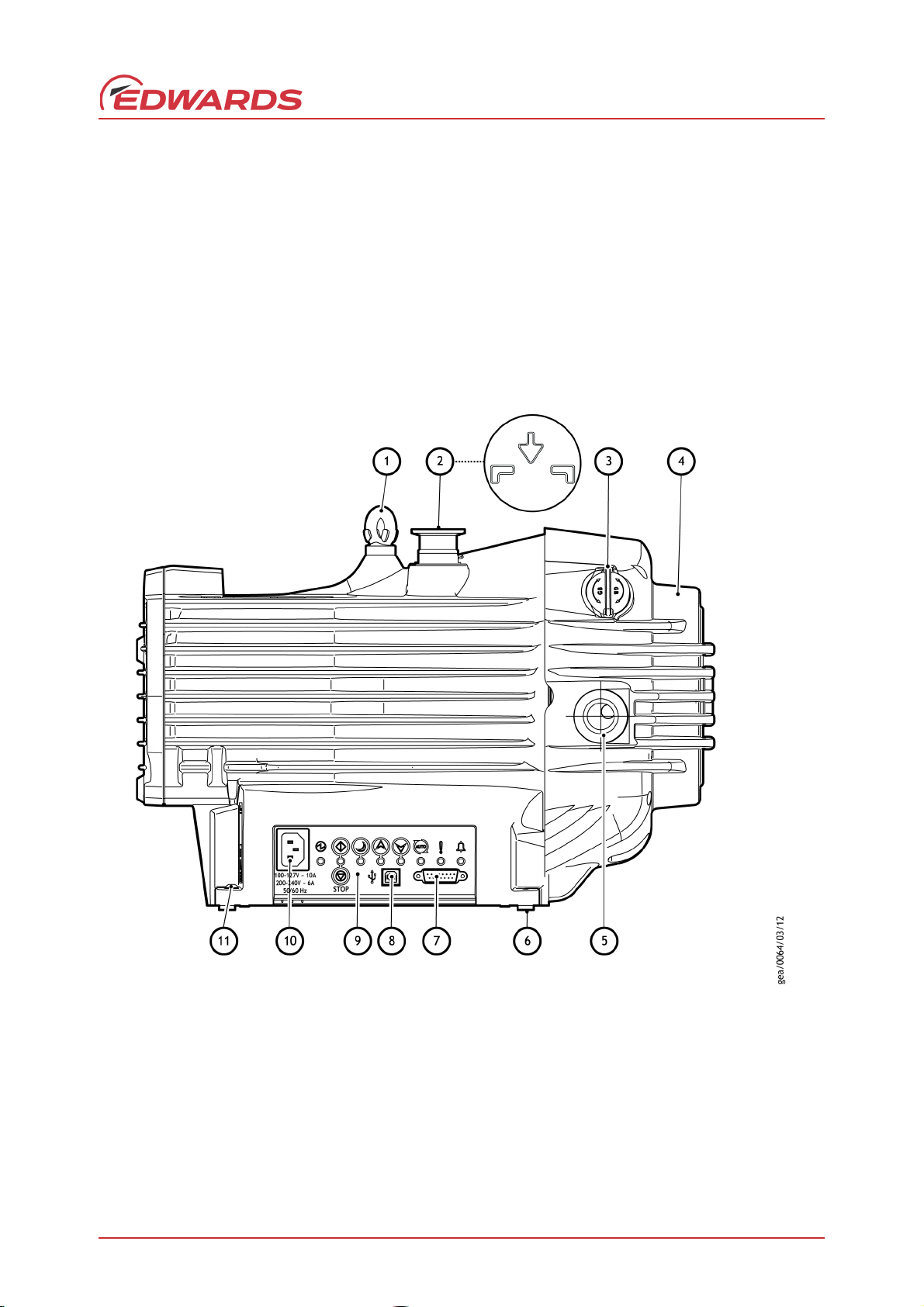
The nXDS pump is shown in Figure 1.
The nXDS pump is a truly dry vacuum pump as all the bearings, with their hydrocarbon lubricant, are isolated from
the vacuum space. The nXDS pump is suitable for use on vapour handling processes, and may be used for some
pumping applications involving corrosive substances. For information on pumping flammable gases, contact Edwards.
The body of the pump includes a fixed scroll and an orbiting scroll. The orbiting scroll is controlled by an electric
motor through an eccentric cam on the motor drive shaft. The movement of the orbiting scroll, meshed with the
fixed scroll, forms successive crescent shaped volumes in the pump. Gas that enters the pump through the inlet is
compressed by the movement of the orbiting scroll and swept towards the centre of the fixed scroll. The compressed
gas enters the exhaust port near the centre of the fixed scroll and is exhausted from the pump through the outlet.
Refer to Section 2.1 for details of operating conditions.
Page 2 © Edwards Limited 2018. All rights reserved.
Page 11
A735-01-880 Issue F
1. Lifting eye
2. NW25 inlet port
3. Gas ballast control
4. Cooling fan
5. NW25 exhaust port
6. Rubber feet
7. 15-way D-type connector
8. USB port (service mode only)
9. User interface panel
10. Mains power connector
11. Secondary earth bond point
1.4 Pump controller
The integral pump controller manages the supply of current to a three-phase electric motor in accordance with
operating conditions. The controller monitors power and temperature, and will protect the pump in the event of
operation under sustained high load or under fault conditions.
The controller provides the user interface (refer to Figure 1). The pump may be operated in these modes:
Manually, using the buttons on the interface panel. Refer to Figures 2 and 9.
Remotely via serial communications or digital and analogue process control (parallel), via the 15-way D-type
logic interface connector. Refer to Section 1.5.
Figure 1 - nXDS scroll pump
Introduction
© Edwards Limited 2018. All rights reserved. Page 3
Page 12

A735-01-880 Issue F
Introduction
1.5 Logic interface
The pump controller can be operated via the 15-way D-type logic interface connector. The signals on the logic
interface are of the following types:
Control inputs: these are switch-type and analogue signals that are used to control the pump
Status outputs: these outputs identify the status of the system Tab
The logic interface has been designed to support both serial control, parallel control and monitoring, operating
though one connector. For serial control either RS232 or RS485 can be selected.
For Control Modes refer to Table 1.
For Logic interface data refer to Section 2.5.
1.6 Gas ballast control
To pump high vapour loads, gas ballast can be delivered into the pump to prevent condensation of the vapour carried
by the pumped gases.
Air can be introduced to the low vacuum stages through the gas ballast control (Figure 1, item 3). Alternatively, an
inert gas such as nitrogen can be supplied through a suitable external valve and by using the appropriate adaptor,
available as an accessory. Refer to Section 7.
Page 4 © Edwards Limited 2018. All rights reserved.
Page 13
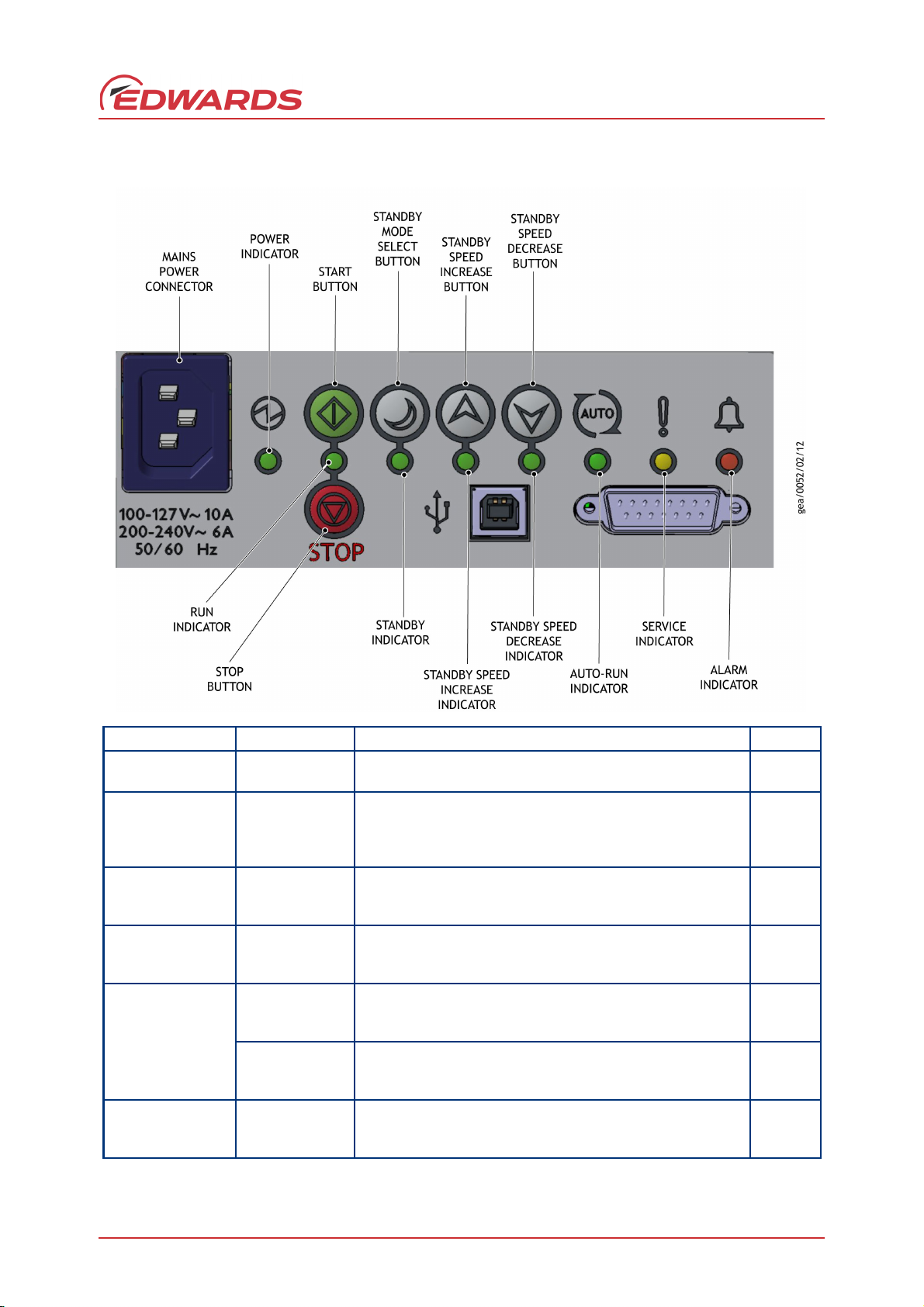
Figure 2 - Quick start guide (manual control mode)
OPERATION SELECT STATUS SECTION
Apply power
MAINS
POWER
The pump will remain off (factory default).
The POWER INDICATOR will illuminate.
3.6.2
Start the pump
START
BUTTON
The pump will accelerate up to full running speed.
*
The RUN INDICATOR will flash while accelerating.
The RUN INDICATOR will remain on when the pump reaches
full speed.
*
The pump is set to 30 Hz rotational full speed (factory default)
4.2.1
Stop the pump STOP BUTTON
The pump will decelerate and stop running.
The RUN INDICATOR will flash while decelerating.
The RUN INDICATOR will go off when the pump has stopped.
4.2.1
Select and deselect
the standby speed
STANDBY MODE
SELECT BUTTON
When engaged, the STANDBY INDICATOR will illuminate and
the pump will run at the standby speed setting. Factory
default is 70% of full speed.
4.2.2
Increase or
decrease the pump
speed when in
standby mode
STANDBY SPEED
INCREASE
BUTTON
The pump speed will increase.
The INCREASE STANDBY INDICATOR will remain illuminated
when the pump reaches a maximum of 100% of full speed.
4.2.2
STANDBY SPEED
DECREASE
BUTTON
The pump speed will decrease.
The DECREASE STANDBY INDICATOR will remain illuminated
when the pump reaches a minimum of 67% of full speed.
4.2.2
Select and deselect
the Auto-run
function
START or STOP
BUTTON (>8 sec)
When engaged, the AUTO-RUN INDI CATOR will illuminate.
The pump will re-start automatically after the power has
been restored.
4.5
A735-01-880 Issue F
Introduction
© Edwards Limited 2018. All rights reserved. Page 5
Page 14
A735-01-880 Issue F
Introduction
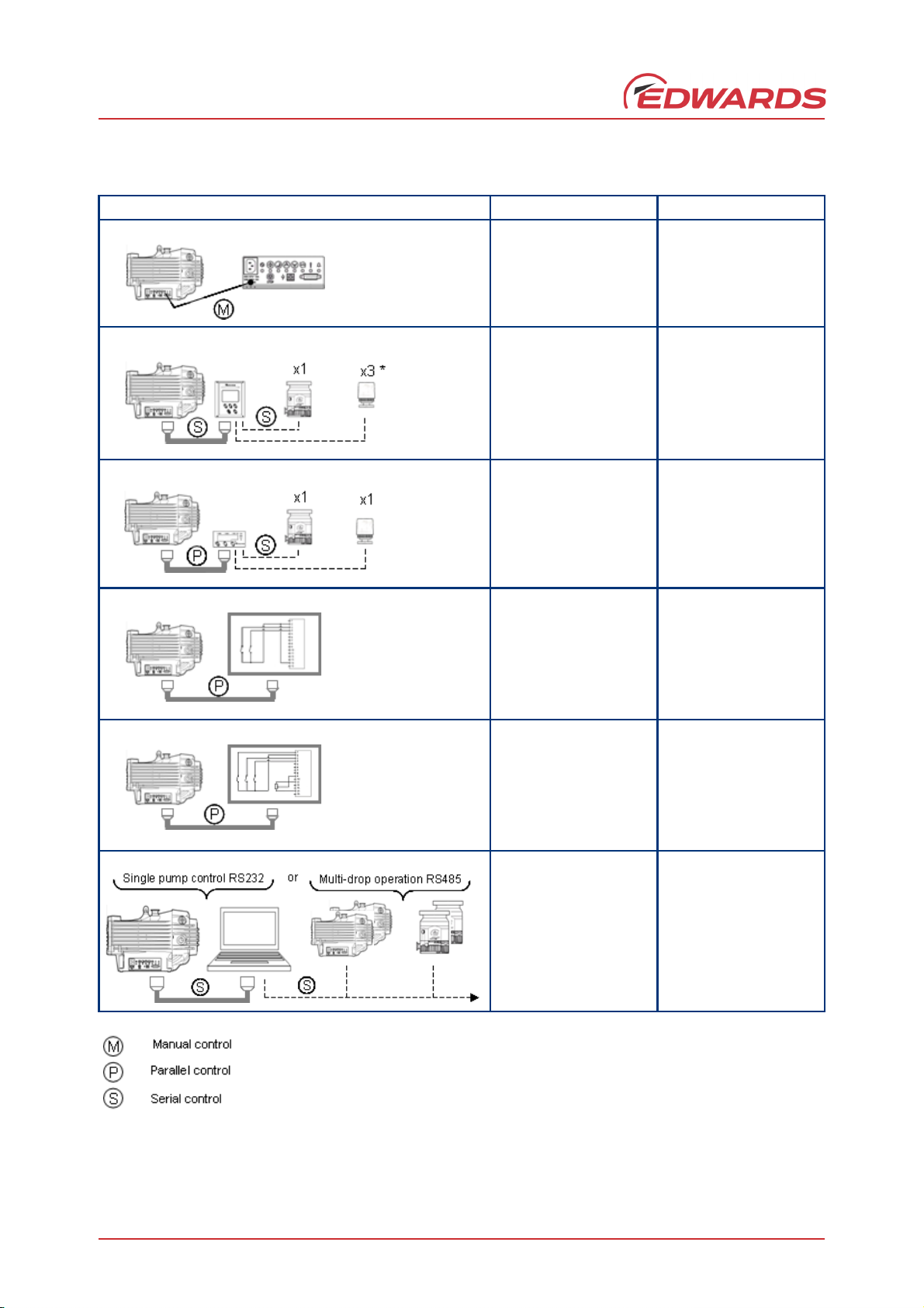
Table 1 - nXDS Control modes
Configuration Control mode Manual/Section
Manual control
via
nXDS user interface
Serial control
via (TIC)
*Turbo Instrument
Controller or
Tu r b o C o n t r o l l e r
Parallel control
via (TAG)
Turbo & Active Gauge
Controller
Parallel control
via Digital I/O
e.g. PLC control
Section 1
Figure 2
in this manual
Manual
D397-22-880
Manual
D395-92-880
Section 1.4
in this manual
Parallel control
via Digital I/O and
Analogue speed
control source
Serial control
via RS232 or
RS485 Comms
Interface
Note: Table 1 shows additional Edwards products, such as DX / nEXT Turbo pumps and active gauges that can be
controlled at the same time using the various control methods displayed above.
Section 4.4
Figure 11
Manual
A735-01-860
Page 6 © Edwards Limited 2018. All rights reserved.
Page 15
A735-01-880 Issue F
WARNING
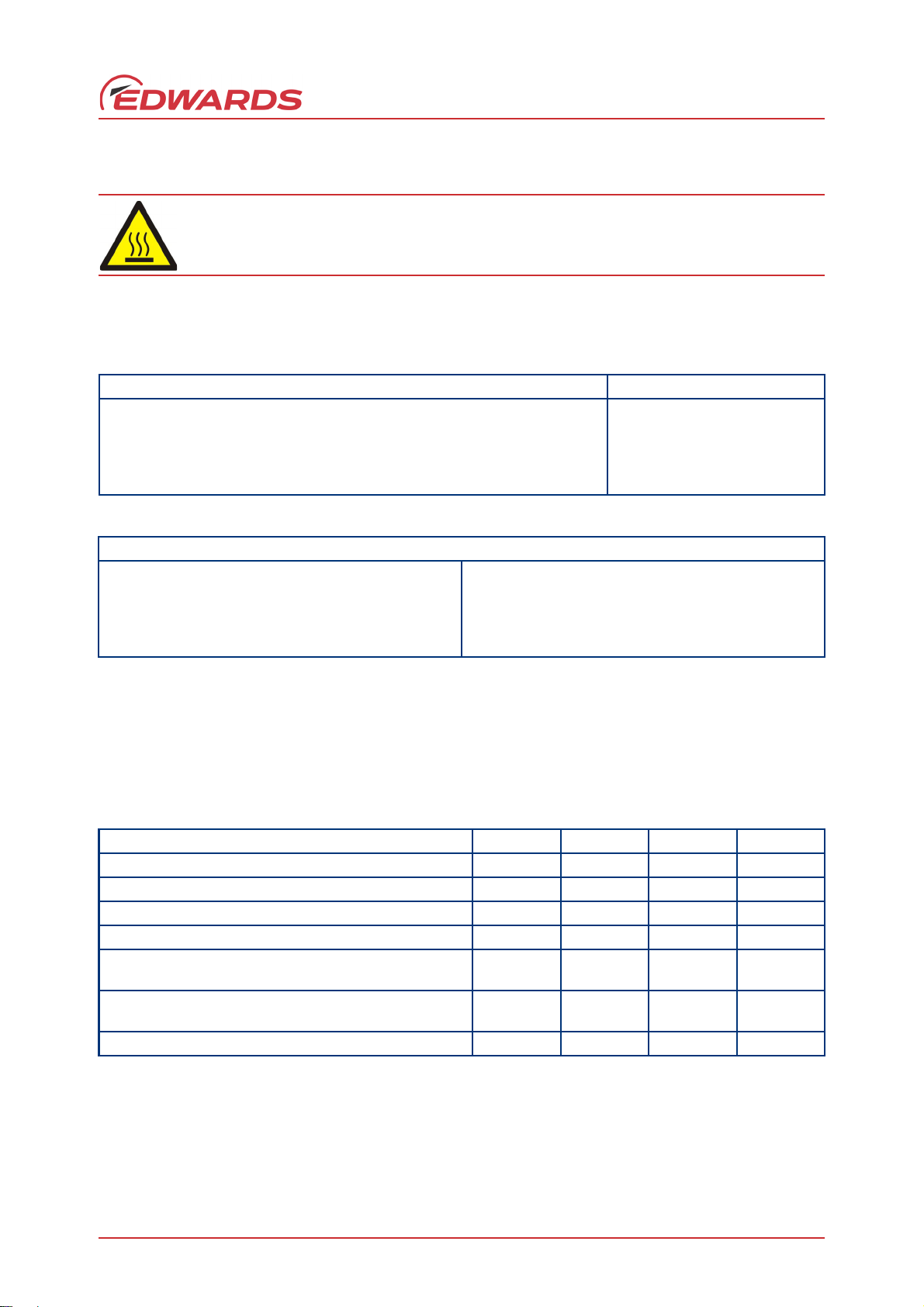
2Technical data
If the nXDS pump is operated outside the specified limits, the pump housing may become hot.
2.1 Operating and storage conditions
Table 2 - Operating and storage conditions
Operating and storage conditions nXDS
Ambient temperature range (storage) –30 °C to +70 °C
Ambient temperature range (operation) +5 °C to +40 °C
Maximum humidity (storage in original packaging) 95% RH
Maximum humidity (operation) 90% RH
Table 3 - Environmental conditions
Environmental conditions
Pollution Pollution degree 2
Installation Installation category II
Altitude restriction Max 2000 m
Area of use Indoor
*
The product can be used up to an altitude of 3000 m. However, the product is only ETL certified for use up
to 2000 m.
*
Technical data
2.2 Performance
2.2.1 General
Tab l e 4 - G en e ra l ch ara c t e ri s t i cs
Description nXDS6i nXDS10i nXDS15i nXDS20i
3h-1
Peak pumping speed (m
Maximum permitted continuous inlet pressure (mbar)
Maximum permitted exhaust pressure (bar gauge)
Maximum permitted gas ballast inlet pressure (bar gauge) 0.5 0.5 0.5 0.5
Maximum recommended chamber volume to pump down
from atmospheric pressure (litres)
Maximum pressure rise when stopped, with no inlet or gas
ballast flow (mbar)
Leak tightness (mbar ls
*
These pumps are designed to pump down from atmospheric pressure, but prolonged operation at inlet
pressures higher than specified may reduce bearing life.
†
These pumps are intended to exhaust to atmospheric pressure. High exhaust pressure may reduce tip-seal
life.
‡
Larger volumes may be pumped, but prolonged operation at inlet pressures higher than specified may
reduce bearing life. The nXDS20i is optimised for constant throughput and is not recommended for cyclic
duty.
) 6.2 11.4 15.1 22.0
*
†
‡
-1
)1 x 10
200 200 200 50
1111
25 50 75 75
7777
-6
1 x 10
-6
1 x 10
-6
1 x 10
-6
© Edwards Limited 2018. All rights reserved. Page 7
Page 16
A735-01-880 Issue F
WARNING
Technical data
Note: If the pump is operated outside the specified limits, then the pump housing may become hot; the controller
may reduce the motor speed; and tip seal wear rate will be increased.
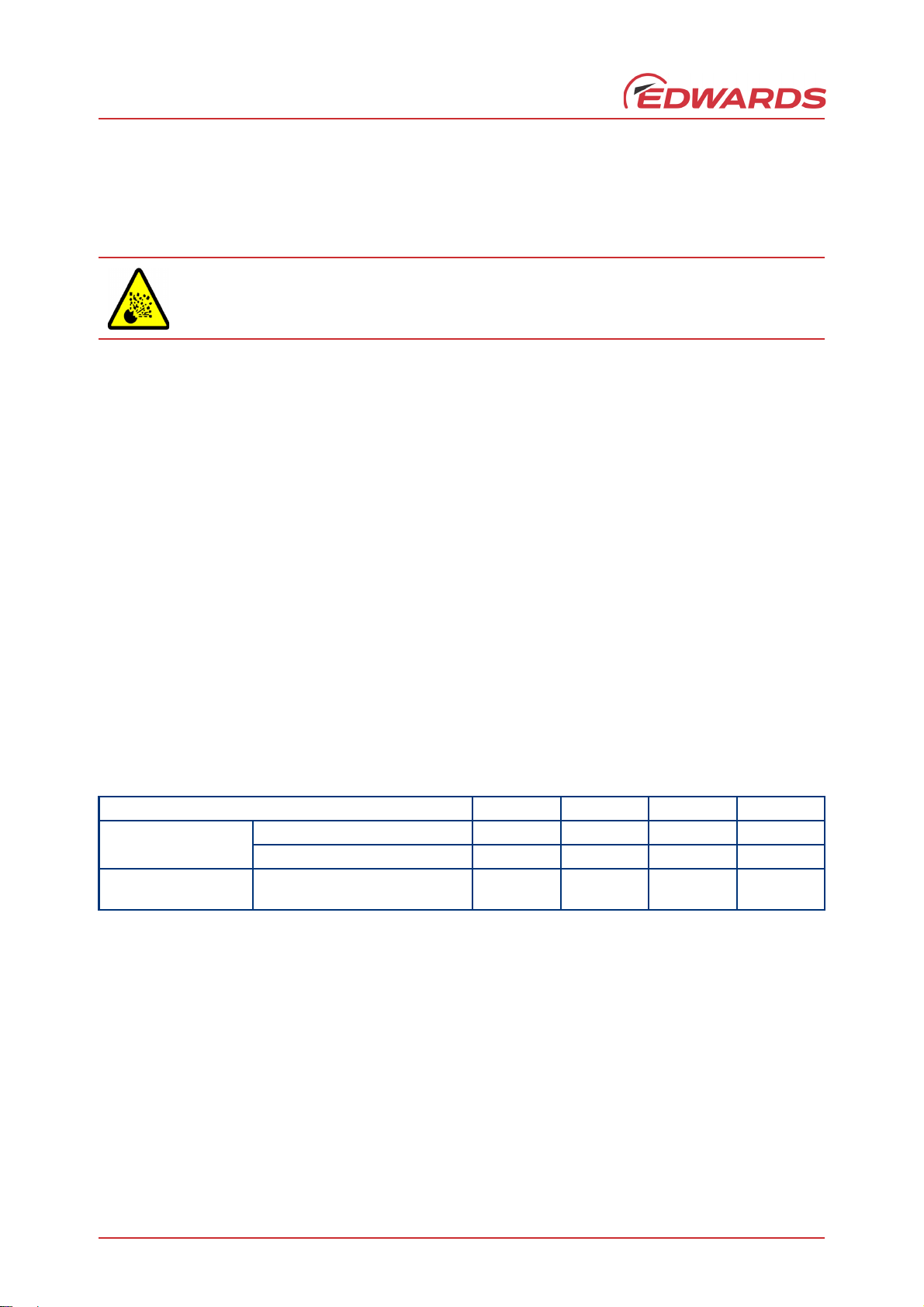
2.2.2 Pumping media
Do not use the nXDS pump to pump pyrophoric materials or dust.
The pump is designed to pump the following gases:
Air
Carbon dioxide
Helium
Carbon monoxide
Nitrogen
Argon
Oxygen (O
)
2
The pump can be used to pump water vapour. Caution must be taken to ensure that vapour does not condense inside
the pump. Refer to Section 4.6.1 on how to prevent condensation of water vapour in the pump.
If pumping a vapour or gas not in the list above, contact Edwards for advice.
2.2.3 Performance characteristics
The position of the gas ballast control defines the performance characteristics of the pump. These performance
characteristics are listed in Table 5.
Table 5 - Performance characteristics
Description nXDS6i nXDS10i nXDS15i nXDS20i
Pump ultimate
(mbar)
Gas ballast flow
(l min-1)
Gas ballast position 0 2 x10
Gas ballast position 1 5 x 10
-2
-2
Gas ballast position 1 12 16 31 24
7 x 10
4 x 10
-3
-2
7 x 10
4 x 10
-3
-2
3 x 10
6 x 10
-2
-2
Page 8 © Edwards Limited 2018. All rights reserved.
Page 17

Figure 3 - nXDS6i Performance characteristics
A735-01-880 Issue F
Technical data
Figure 4 - nXDS10i Performance characteristics
© Edwards Limited 2018. All rights reserved. Page 9
Page 18

A735-01-880 Issue F
Technical data
Figure 5 - nXDS15i Performance characteristics
Figure 6 - nXDS20i Performance characteristics
Page 10 © Edwards Limited 2018. All rights reserved.
Page 19

2.3 Mechanical data
2.3.1 General
A735-01-880 Issue F
Technical data
Parameter nXDS
Overall dimensions (L x W x H) 432 x 282 x 302 mm
Maximum tilt angle 10 degrees
Nominal rotational speed 1800 rpm (30 Hz)
Mass (maximum) 6i - 26.2 kg
Inlet connection NW25
Outlet connection NW25
Table 6 - General mechanical data
10i - 25.8 kg
15i - 25.2 kg
20i - 25.6 kg
2.3.2 Sound and vibration data
Parameter nXDS
Sound pressure, measured at ultimate vacuum 1 metre from the end of the pump
to ISO 3744
Vibration: measured at the inlet port (ISO 3744) Class 1C…< 4.5 mms
Table 7 - Sound and vibration data
52.0 dB (A) ± 2.5
Declared dual number noise
emission values according
with ISO 4871
radial)
–1
(rms
2.3.3 Construction
All surfaces of the pump which are exposed to the pumped gases are free from copper, zinc and cadmium. Exposed
components include: anodised aluminium scrolls, aluminium housing, nickel-plated inlet and exhaust ports, PTFE
composite tip-seals, various stainless steel parts and fluorocarbon elastomer seals.
Other materials of construction include steel, copper, hydrocarbon lubricant and chemically resistant polymers.
2.4 Electrical data
Table 8 - Electrical ratings for continuous operation
Pump Supply (Vac rms) Phase Frequency (Hz) Input current (A rms)
All variants
Area Voltage Rating
Europe 230 V 10 A, 250 V a.c. rms
Japan 100 V 10 A, 250 V a.c. rms
100 - 127 ± 10% Single 50/60 10
200 - 240 ± 10% Single 50/60 6
Table 9 - Recommended regional supply protection
UK 230 V 10 A, 250 V a.c. rms
US 120 V 10 A, 250 V a.c. rms
© Edwards Limited 2018. All rights reserved. Page 11
Page 20

A735-01-880 Issue F
Technical data
2.4.1 Electrical cables
Recommended cord sets and fuses for regional requirements.
Table 10 - Recommended cord sets
Description Rating Coupler type Item number
2
Cord set assembly, UK Cable Style = H05VV-F, 3 x 1.0 mm
70 °C, maximum length of 2.0 metres Straight entry A50505000
Plug Type = BS1363 UK plug
Appliance Coupler = IEC60320 style C14
Fuse Type = BS1363 10 Amp fuse, to an
IEC60320 style
Cord set assembly, Europe Cable Style = H05VV-F, 3 x 1.0 mm
70 °C, maximum length of 2.0 metres Straight entry A50506000
Plug Type = European Schuko VDE approved,
16 A 250 V rated with dual earthing contact
Appliance Coupler = IEC60320 style C14 N/A
Cord set assembly,
USA/Canada
Cable style = SJT, 3 x 18 AWG, 300 V, 70 °C,
VW-1 maximum length of 2 metres Straight entry A50507000
Plug Type = NEMA, 5-15P plug
Appliance Coupler = IEC 60320 style C14
, 300 V,
2
, 300 V,
2.5 Logic interface data
The pumps have a 15-way D-type logic interface connector located on the user interface panel (Figure 1, item 7).
The logic interface connector can be plugged directly into the Edwards 200W Turbo Instrument Controller (TIC) or
turbo controller, or Turbo and Active Gauge controller (TAG). A suitable connector mating half must be used (not
supplied) to connect the nXDS pump to the customer control system. Refer to Table 11 for the interface technical
data and Table 12 for the logic interface pins for the electrical connections.
Table 11 - Logic interface technical data
Logic interface description
Connector
Start, serial enable and remote enable:
Standby control input:
Analogue and RS485 enable control inputs:
Analogue speed input
Voltage accuracy ± 5% full scale
*
Enable control voltage: low (closed) 0 to 0.8 V d.c. (l
Disable control voltage: high (open) 4 to 26.4 V d.c. (Internal pull up to 6.4 V nominal)
Enable control voltage: low (closed) 0 to 0.8 V d.c. (l
Disable control voltage: high (open) 4 to 26.4 V d.c. (Internal pull up to 3.2 V nominal)
Enable control voltage: low (closed) 0 to 0.8 V d.c. (l
Disable control voltage: high (open) 4 to 52.8 V d.c. (Internal pull up to 6.4 V nominal)
15-way D-type (male)
= 0.55 mA nominal)
OUT
= 0.3 mA nominal)
OUT
= 0.55 mA nominal)
OUT
0 to 10 V d.c. directly proportional to the motor speed
e.g. 0 V = 0 Hz, 10 V = 30 Hz
Page 12 © Edwards Limited 2018. All rights reserved.
Page 21

Table 11 - Logic interface technical data (continued)
Logic interface description
NORMAL status output:
Type Open collector transistor plus pull up resistor.
< Normal speed (default 80%) OFF (4.7 k pull up + diode to 12 V d.c.)
Normal speed ON (< 0.8 V d.c. sinking 10 mA)
Maximum current rating 10 mA
Maximum voltage rating 28.8 V d.c.
FAIL status output:
Type Open collector transistor plus pull up resistor.
Fail OFF (4.7 k pull up + diode to 12 V d.c.)
OK ON (< 0.8 V d.c. sinking 10 mA)
Maximum current rating 10 mA
Maximum voltage rating 28.8 V d.c.
Analogue 10 V reference
Voltage accuracy ± 2% full scale
Output current 5 mA for specified accuracy
*
Mating half of connector not supplied
+ 10 V d.c. analogue voltage reference
Unipolar output with diode protection
A735-01-880 Issue F
Technical data
Table 12 - Logic interface connector pins
Pin Number Signal Polarity Use
1 Analogue Speed Enable-
control Input
2 0 V Control Reference - 0 V reference for ALL control and status signals listed within
3 START / STOP – Control
Input
4STANDBY – Control Input /
Serial-RX / RS-485 A-
5 Serial Enable – Control
Input
6 RS-232 / RS-485 – Control
Input
7 FAIL – Status Output /
Serial-TX / RS-485 B+
8 0 V Control Reference - 0 V reference for ALL control and status signals listed within
9 Analogue Speed – Control
Input
10 Chassis / Screen - Screen
11 +10 V Analogue Reference
– Control Output
12 Chassis / Screen - Screen
- Connect to Pin 2 (0 V) to enable analogue speed control via
Pin 9.
this table.
- Connect to Pin 2 (0 V) to START the nXDS pump system.
- Connect to Pin 2 (0 V) to enable STANDBY speed when the
SERIAL ENABLE control input is inactive.
- Connect to Pin 2 (0 V) to enable serial communications.
- Default configuration is RS-232 with Pin 6 unconnected.
Connect to Pin 2 (0 V) to enable RS-485 serial
communications.
- Logic HIGH when a fail / fault condition exists and the SERIAL
ENABLE control input is inactive.
this table.
- 0-10 V Analogue Input: 0 V = 0% Speed; +10 V = 100% Speed
Positive +10 V analogue voltage reference output: 5 mA;
uni-polar output, diode protected.
© Edwards Limited 2018. All rights reserved. Page 13
Page 22

A735-01-880 Issue F
Technical data
Table 12 - Logic interface connector pins (continued)
Pin Number Signal Polarity Use
13 Not Connected - Unused control pin.
14 REMOTE – Control Input - Connect to Pin 2 (0 V) to enable remote control via Parallel or
15 NORMAL – Status output - Logic LOW when the pump rotational speed is at normal
2.6 LED indicators
Serial control modes.
speed or above.
Figure 7 - LED indicators
The nXDS pump has eight indicator LED’s
Table 13 - LED indicators
LED Description Details
1 Power indicator Indicates that electrical mains supply to the pump is ON
2 Run indicator Indicates that the pump is running. Refer to Section 4.2.1.
3 Standby mode indicator
Standby speed increase
4
indicator
Standby speed decrease
5
indicator
6 Auto-run indicator
7 Service indicator
8 Alarm indicator Indicates an Alarm has been triggered. Refer to Section 5.11.6.
Indicates that the Standby mode has been selected. Refer to
Section 4.2.2.
The indicator will blink with every short push of the Standby speed
increase button. The indicator will remain ON when maximum standby
speed has been reached. Refer to Section 4.2.2.
The indicator will blink with every short push of the Standby speed
decrease button. The indicator will remain ON when minimum standby
speed has been reached. Refer to Section 4.2.2.
Indicates that the Auto-run mode has been selected. Refer to
Section 4.3.
Indicates that a service interval has been reached. Refer to
Section 5.10.
Page 14 © Edwards Limited 2018. All rights reserved.
Page 23

A735-01-880 Issue F
WARNING
3 Installation
3.1 Safety
Obey the safety instructions in this section and take note of appropriate precautions. If not, injury
to people and damage to equipment can result.
Prevent any part of the human body coming into contact with the vacuum.
The Edwards nXDS pump is not intended for pumping explosive gases continuously (refer to
Section 1.2).
Ensure that the pump is suitable for the application. If in doubt, refer to the Edwards guidelines on vacuum pump
and vacuum system safety (see associated publications at the end of the contents list at the front of this manual),
or contact Edwards for advice.
A suitably trained and supervised technician must perform the installation of the pump. Obey the safety instructions
listed below, especially when connecting the pump into an existing system. Details of the specific safety precautions
are given at the appropriate point in the instructions.
Installation
Wear the appropriate safety clothing if contact with contaminated components is anticipated. Dismantle and
clean contaminated components inside a fume cupboard.
Vent and purge the vacuum system before starting installation work.
Ensure that the installation technician is familiar with the safety procedures that relate to the products
handled by the pumping system.
Disconnect the other components in the pumping system from the electrical supply to prevent accidental
operation.
3.2 System design considerations
Consider the following points when designing the pumping system:
Edwards recommend the use of a foreline vacuum isolation valve to allow the pump to warm up before pumping
condensible vapours or if a vacuum needs to be maintained when the pump is not running.
Use a suitable valve to isolate the pump from the vacuum system if the pump needs to warm up before pumping
condensable vapours or if vacuum needs to be maintained when the pump is switched off.
Avoid high levels of heat input into the pump from the process gases, otherwise the pump may overheat and cause
the thermal protection system to operate.
Ensure that the exhaust pipeline cannot become blocked. If an exhaust isolation valve is installed, ensure that the
pump cannot be operated with the valve closed. Refer to Section 3.5.
Provide for a purge of inert gas when the pumping system is shut down, to dilute dangerous gases to safe
concentrations. Contact the Edwards Application team for further advice on dilution requirements if required.
© Edwards Limited 2018. All rights reserved. Page 15
Page 24

A735-01-880 Issue F
Installation
Figure 8 - Installation drawing
Note: All dimensions in mm. External dimensions are the same for all variants.
Page 16 © Edwards Limited 2018. All rights reserved.
Page 25

A735-01-880 Issue F
WARNING
WARNING
WARNING
3.3 Unpack and inspect
Use suitable lifting equipment to move the nXDS pump. The maximum pump mass is 27 kg.
Mechanical lifting equipment should be attached to the lifting eye; loose slings should not
be used.
Take care when moving the pump into position. Its mass may make it difficult to slide. The
fan cowl is shaped to provide a handhold for positioning; the pump must not be lifted using
this handhold.
Remove all packing materials, remove the pump from its packing box, remove the protective covers from the inlet
and outlet ports and inspect the pump. If the pump is damaged, notify the supplier and carrier in writing; state the
item number of the pump together with the order number and supplier's invoice number. Retain all the packing
materials for inspection. Do not use the pump if it is damaged. If the pump is not to be used immediately, replace
the protective covers. Store the pump in the conditions described in Section 6.1. Refer to Section 6.2 for disposal of
materials.
3.4 Position the pump
Installation
If the pump is to be used on the floor of a work area, position the power lead and the exhaust and
inlet hoses with care. Ensure that personnel in the area are aware of any obstructions around the
pump.
Provide a firm, level platform for the pump. Locate the pump so that the gas ballast control and the user controls
are accessible.
If the pump will be located inside an enclosure, ensure that there is adequate ventilation at both ends of the pump,
so that the ambient temperature around the pump does not exceed 40 °C. There must be a minimum space of 25 mm
between the pump and the enclosure walls.
3.4.1 Mechanical fixing
Note: The pump can be secured by using the four holes located on each corner of the pump base. Edwards
recommends using M8 bolts.
3.5 Connect to the vacuum system
If pumping dangerous gases or vapours, connect the exhaust to a suitable treatment plant to
prevent the discharge of dangerous gases and vapours to the surrounding atmosphere.
If the pump is operated with the exhaust line blocked, high pressure may be generated in the
exhaust line pipework.
Refer to Figure 1. Before connecting the pump to the vacuum system, remove the plastic cap from the inlet and
exhaust, and ensure that the inlet strainer is fitted to the pump inlet port. Use appropriate NW25 vacuum fittings for
connection to the system.
© Edwards Limited 2018. All rights reserved. Page 17
Page 26

A735-01-880 Issue F
CAUTION
WARNING
Installation
Take note of the following information when connecting the pump to the vacuum system:
To minimise noise and exhaust emissions, it is recommended that the pump is connected to an exhaust line
or a silencer (refer to Section 7).
For optimum pumping speeds, ensure that the pipeline connected to the pump inlet is as short as possible
and has a suitable internal diameter.
Support the vacuum pipeline to prevent loading of the coupling joints.
A pressure of 3 barg may be generated in the exhaust pipework if the pump is operated with the exhaust line
blocked. Connect the pump using appropriate pipework and fittings.
If necessary, incorporate flexible bellows in the system pipelines to reduce the transmission of vibration and
to prevent loading of the coupling joints. If using flexible bellows, ensure that bellows have a maximum
pressure rating which is greater than the highest pressure that can be generated in the system. Edwards
bellows are recommended.
Incorporate an inlet isolation valve in the pipeline from the vacuum system to the pump to isolate the
vacuum system from the pump when it is switched off and prevent suck-back of process gases and debris into
the vacuum system.
Ensure that the sealing surfaces are clean and scratch-free.
Edwards recommends using an exhaust extraction system suitable for use with all process gases that will be pumped.
Ensure that the exhaust extraction system cannot become blocked or obstructed when the pump is operating.
A small amount of tip seal wear product may collect in the exhaust duct of the pump. The dust may be blown out
with the initial burst of air after the pump has been vented. This is quite common and the amount of dust seen will
reduce over time.
Leak test the system and seal any leaks found after pump installation.
3.6 Electrical installation
3.6.1 Fuses and circuit breakers
Ensure that the electrical installation of the pump conforms to local and national safety
requirements. The pump must be connected to a suitably fused and protected electrical supply
with a suitable earth point. For recommended fuse ratings and cord sets refer to Section 2.4.
Ensure that access to the pump electrical supply cable is not obstructed when locating the pump.
If using an earth leakage device, for example, a Residual Current Device (RCD), use a 30 mA (minimum) rated
unit to avoid trip during start up.
The live conductor is fused inside the pump controller whilst the neutral conductor is not. An external RCD
should be installed to guard against damage in the event of a short circuit between neutral and earth.
For recommended protection ratings, refer to Table 9 in Section 2.4.
Page 18 © Edwards Limited 2018. All rights reserved.
Page 27

A735-01-880 Issue F
3.6.2 Electrical supply connection
Use an IEC60320 connector (C13) and cable that meets local electrical standards when connecting to the pump. The
pump must be earthed via the earth conductor of the IEC60320 connector. A list of cable specifications is available
in Section 2.4 of this manual.
Edwards recommends fitting a separate earth to the pump using a non-insulated braid or a separate insulated green/
yellow conductor. The conductor must be a minimum of 14 AWG. Use the M5 x 10 screw and shake proof washer
located on the rear of the pump housing (refer to Figure 1) to secure the earth conductor to the pump.
3.6.3 Disconnect the pump from the electrical supply
Before removing the physical electrical supply connection to the pump, via the IEC60320 cable (C13), isolate the
Mains supply (refer to Figure 1).
3.7 Connection for remote control and monitoring
To operate the pump using parallel or serial control, use the 15-way D-type connector on the user interface panel
(refer to Figure 1, item 7). Refer to Table 12 for full details of the logic interface pins.
3.7.1 Connect the logic interface to the control equipment
Installation
The pump can be controlled using a hardware parallel control interface and/or via commands sent over a serial
interface.
To control the pump using the hardware parallel interface, refer to Section 4.3 for more information. To use the
serial interface or to work with a mixture of parallel and serial control, refer to manual A735-01-860.
© Edwards Limited 2018. All rights reserved. Page 19
Page 28

A735-01-880 Issue F
This page has been intentionally left blank.
Page 20 © Edwards Limited 2018. All rights reserved.
Page 29

A735-01-880 Issue F
CAUTION
WARNING
4 Operation
Ensure that the system design does not allow the exhaust pipeline to become blocked.
A fine dust may be emitted from the exhaust of the scroll pump during start up, particularly when the pump is
new or if new tip seals are fitted.
4.1 Operational modes
The nXDS pump implements three control modes:
Manual Control Mode - using buttons on user interface panel
Parallel Control Mode - via 15-way D-type logic interface connector on user interface panel
Operation
Serial Control Mode (including Serial Interlock) - via 15-way D-type logic interface connector on user
interface panel
The Control Mode is determined by the way the pump is started. Once started, the pump can only be stopped by the
mode in which it was started, unless the power is cycled by isolation from the electrical supply.
4.2 Manual operation
The pump control functions of the user interface panel are detailed in Figure 9.
© Edwards Limited 2018. All rights reserved. Page 21
Page 30

A735-01-880 Issue F
1. Mains power connector
2. Power connected indicator
3. Start button with indicator
4. Standby button with indicator
5. Increase standby speed button with indicator
6. Decrease standby speed button with indicator
7. Auto-run enabled indicator
8. Service indicator
9. Alarm indicator
10. 15-way D-type connector
11. USB port (Service mode only)
12. Stop button
Operation
Figure 9 - User interface panel
4.2.1 Start and stop
Use the buttons (Figure 9, items 3 and 12) to start and stop the pump. Note that the stop command does not isolate
the pump from the electrical supply.
4.2.2 Standby
Operation at reduced speed will further improve tip seal and bearing service life. Vacuum performance will be
reduced when operating at standby speed.
Press the Standby button to select standby mode. The pump will initially run at factory default standby speed (70%
of full speed). The speed can be adjusted using the increase and decrease standby speed buttons. The maximum
standby speed is 100% of the default run speed and the minimum standby speed is 67% of the default run speed. A
single short push will change the speed by 1% of the default run speed, holding the button will change the speed by
1%/sec. Once adjusted, the pump will return to this new user-defined speed each time standby speed is selected.
The Standby button must be pressed to return to normal run speed.
Page 22 © Edwards Limited 2018. All rights reserved.
Page 31

4.3 Parallel control and monitoring
CAUTION
1. Start switch
2. Standby switch (optional)
3. nXDS pump logic interface
Figure 10 - Logic interface connections - parallel control
A735-01-880 Issue F
Operation
If using the normal and fail lines to drive the coils of d.c. relays, include a back EMF suppression diode in parallel
with each relay coil to protect the pump.
Connect the control equipment to the control input pins of the logic interface mating half. Refer to Table 11 to
identify the logic interface connector pins. The control inputs are as follows:
Start
Standby speed
Analogue speed
To activate any of these control inputs, connect the relevant control input (pin 14) to the 0 V control reference.
To monitor the normal status output, connect the control equipment to the Normal status output (pin 15) and to pin
2 of the logic interface mating half. The output can be used to control other devices in the pumping system. The
output can drive a low power relay of up to 24 V coil rating (up to 10 mA).
To monitor the fail status output, connect the control equipment to the fail output (pin 7) and to pin 2 of the logic
interface mating half. The output can be used to control other devices in the pumping system. The output can drive
a low power relay of up to 24 V coil rating (up to 10 mA).
© Edwards Limited 2018. All rights reserved. Page 23
Page 32

A735-01-880 Issue F
1. Start switch
2. Analogue control switch
3. nXDS pump logic interface
Operation
4.4 Analogue speed control
The Analogue Speed input is a process control source which enables the nXDS Scroll pump to run at variable operating
speeds. This speed control source is an alternative to standby speed control.
Figure 11 - Logic interface connections - analogue speed control
Note: 0.1 V
Page 24 © Edwards Limited 2018. All rights reserved.
1% of Default Run Speed
Page 33

Figure 12 - Analogue speed control
A735-01-880 Issue F
Operation
Note: Voltages below 6.7 V will result in a clamped speed of 67% of full speed.
4.4.1 Hardware configuration
Using the 15-way D-type connector (Figure 1, item 7) apply the following signal configurations to enable the Analogue
Speed Control source (refer to Table 12):
Connect the Analogue Speed Enable control input (pin 1) to the 0 V Control Reference (pin 2).
Connect a suitably calibrated analogue voltage source (0 to +10 V), for example, (DAC) to the analogue speed control
input (pin 9). Alternatively connect the output of a potentiometer referenced to the pump reference voltage (pin 11)
to the analogue speed control input (pin 9). Refer to Figure 11. The 0 V rail of the external voltage source must be
connected to the 0 V Control Reference (pin 2) of the pump controller.
4.4.2 Operation
A +10 V input equates to a mechanical running speed which is equal to: 100% of the default run speed, that
is, 30 Hz.
The minimum running speed provided by the Analogue Speed control source, is clamped at the minimum
Standby Speed Setting, that is, approximately 67% of the default run speed of 20 Hz.
The maximum running speed provided by the Analogue Speed control source is clamped by the maximum
Standby Speed Setting, that is, 100% of the default run speed of 30 Hz.
© Edwards Limited 2018. All rights reserved. Page 25
Page 34

A735-01-880 Issue F
Operation
4.5 Auto-run
The auto-run setting configures the pump to start at power-up without any customer intervention. This parameter is
customer configurable via serial communications, or using the START / STOP buttons. Holding down either the START
or STOP button, for more than eight seconds, will enable or disable the auto-run setting. The status of the auto-run
setting is visible via the auto-run LED.
The pump can be stopped using either manual, parallel or serial control modes whilst in auto-run.
4.6 Use of gas ballast control
The gas ballast control can be used to optimise the performance of the scroll pump for the application. The
performance characteristics of the pump with gas ballast on are shown in Section 2.2.3. The position of the gas
ballast control can be changed when the pump is either off or operating.
4.6.1 Gas ballast control
Use the gas ballast control to introduce air into the final stage of the pump. Use of gas ballast will reduce the
condensation of vapours in the pump; the condensates would contaminate the pump.
There are only two positions, 0 and 1. The gas ballast control knob will rotate 360° in either direction at 90° intervals.
Gas ballast OFF (position 0). Use this setting to:
achieve ultimate vacuum
pump dry gases.
Gas ballast ON (position 1). Use this setting to:
pump low concentrations of condensable vapours
decontaminate the pump.
4.7 Start up procedure
Use the procedure below to start up the pump:
1. Ensure that any vacuum system isolation valve is closed (if fitted).
2. With the mains supply to the pump isolated, connect a recommended lead to the electrical socket on the pump
(refer to Figure 1).
3. Apply power.
4. Start the pump system using the appropriate control source, that is, using the Start button in manual control
mode (refer to Figure 9); the Start/Stop control input (refer to Tab le 1 2 , pin 3) in parallel control mode or a
Start command in serial control mode.
5. Open the vacuum system isolation valve, if fitted.
Page 26 © Edwards Limited 2018. All rights reserved.
Page 35

A735-01-880 Issue F
4.8 To achieve ultimate vacuum
In order to achieve the best possible vacuum, the pump should be operated with the gas ballast control turned off.
However, if the pump, or elements of the vacuum system it is attached to, are new or have been newly fitted, some
atmospheric moisture may be present. If atmospheric moisture is present, run the pump with gas ballast on for
20 minutes before turning gas ballast off. If moisture is allowed to remain, the performance of the pump will be
impaired.
4.9 To pump condensable vapours
Select gas ballast ON when there is a high proportion of condensable vapours in the process gases. This will assist the
vapours to pass through the pump without condensing and keep the pump performance from degrading.
4.10 Shut down
Use the procedure below to shut down the pump:
1. If shutting the pump down prior to a period of storage, remove any process gases by running on a gas ballast for
at least one hour.
2. Close any vacuum system isolation valves to prevent suck-back into the vacuum system (where fitted).
Operation
3. Stop the pump system using the appropriate control source, that is, using the Stop button in manual control
mode (refer to Figure 9); the Start/Stop control input (refer to Ta b le 1 2, pin 3) in parallel control mode or a Stop
command in serial control mode.
4. Vent the nXDS pump system using the gas ballast control or the valve on the inlet.
5. Isolate the Mains supply.
© Edwards Limited 2018. All rights reserved. Page 27
Page 36

A735-01-880 Issue F
This page has been intentionally left blank.
Page 28 © Edwards Limited 2018. All rights reserved.
Page 37

5Maintenance
CAUTION
WARNING
WARNING
WARNING
WARNING
WARNING
5.1 Safety information
Obey the safety instructions in this section and take note of appropriate precautions. Failure to
observe these instructions may result in injury to people and damage to equipment.
In order to maintain the ATEX certification, all maintenance work has to be carried
out in accordance with this nXDS instruction manual, the nXDS Replacement Tip Seal
manual and the nXDS maintenance manual, using only genuine Edwards spare parts.
Disconnect the pump and other components from the electrical supply to prevent accidental
operation.
A735-01-880 Issue F
Maintenance
The pump may be contaminated with the process chemicals that have been pumped during
operation. If so, ensure that the pump is decontaminated before maintenance and adequate
precautions taken to protect people from the effects of dangerous substances if contamination has
occurred.
Do not touch or inhale the thermal breakdown products of fluorinated materials which may be
present in the pump if the pump has been heated to 260 °C and above. Fluorinated materials are
safe in normal use but can decompose into very dangerous substances (which may include
hydrofluoric acid) if heated to 260 °C and above. The pump may have overheated if it was misused
or if it was in a fire. Safety Data Sheets for fluorinated materials used in the pump are available on
request; contact the supplier or Edwards.
External surfaces of the pump should be cleaned using a damp cloth. Care must be taken with solvent-based
cleaning fluids as they may remove important information from the product labels.
The pump is designed to require little user maintenance. Observe the following guidelines when carrying out
maintenance on the pump:
Ensure the maintenance is done by a suitably trained and supervised technician. Obey local and national
safety requirements.
Ensure the maintenance technician is familiar with the safety procedures which relate to the products
processed by the pumping system.
Check that all the required parts are available and are of the correct type before starting work.
Isolate the pump and other components from the electrical supply to prevent accidental operation.
Allow the pump to cool for at least 3 hours before starting maintenance work.
© Edwards Limited 2018. All rights reserved. Page 29
Page 38

A735-01-880 Issue F
Maintenance
5.2 Maintenance plan
More frequent maintenance may be required if the pump is used to pump aggressive gases or vapours, such as
solvents, organic substances and acids, or if the pump is operated continuously at the higher end of its operating
temperature.
Table 14 - Maintenance plan
Operation
Inspect and clean the inlet strainer 12 No 5.3
Inspect and clean the external fan cover if required 12 No 5.4
Check the pump performance 30 Yes 5.5
Replace the pump bearings 60 Yes 5.6
Replace the pump controller 120 Yes 5.6
Electrical safety check 60 No 5.8
For service indicator codes, refer to Section 5.10.
Frequency
(months)
Service
indicator
Section
reference
5.3 Inspect and clean the inlet strainer
Whenever the pump is disconnected from the vacuum system, or on an annual basis, Edwards recommends:
Removing the inlet strainer from the pump inlet (refer to Figure 1) and remove any debris that may have
accumulated.
Inspecting the inlet strainer and if necessary, clean it with a cleaning solution suitable for the substances
pumped. Refit the inlet strainer before reconnecting the pump to the vacuum system. Refer to Section 3.5.
5.4 Clean the external fan cover
If the fan cover is not kept clean, the air flow over the pump can be restricted and the pump may overheat.
1. Switch off the pump and disconnect it from the electrical supply.
2. Use a dry cloth and a soft brush to remove dirt and deposits from the fan cover.
5.5 Check the pump performance (service indicator)
The service indicator, (flashing ON 1s / OFF 1s) is triggered as a reminder to check the performance of the pump.
The service indicator will flash to indicate that a tip-seal change may be required (based on typical tip-seal life). If
after checking, the pump is no longer achieving the required performance, Edwards recommends carrying out a tipseal replacement (refer to Section 5.10).
If however the pump performance is still within acceptable limits, or is performing satisfactorily, the tip-seal
replacement can be delayed.
If operating a preventative maintenance plan, depending upon the particular regime, a tip-seal change can be carried
out at this time irrespective of the pump performance.
To reset the service indicator, refer to Section 5.10.
Page 30 © Edwards Limited 2018. All rights reserved.
Page 39

A735-01-880 Issue F
5.6 Replace the tip-seals
This information is applicable to the nXDS replacement tip seal kit that must be fitted. Refer to Section 7.3.1 for
ordering information.
A tip-seal replacement should be carried out to maintain or restore the pumps performance. The frequency for
replacing the pump tip-seals is determine by the following factors:
The pump has reached a service interval. Refer to Sections 5.5 and 5.7.
The pump is no longer achieving the required performance.
If the pump is no longer achieving the required performance prior to a service interval being reached, Edwards
recommends first following the guide lines, refer to Section 5.11.2.
Note: There may be a running-in period after fitting your new tip-seals. The performance should improve over a
period of 24 to 48 hours. If the pump performance does not improve sufficiently after the running-in period,
please contact Edwards for advice.
For information on how to replace the nXDS tip-seals and Health and Safety, refer to the nXDS replacement tip seal
kit instruction manual A735-02-840 which is included on the CD manual. Also refer to Youtube video at
https://www.youtube.com/watch?v=vKnh9dxOyhE.
Maintenance
5.7 Replace the pump bearings (service indicator)
The service indicator, (flashing ON 3s / OFF 1s) is triggered to indicate that a bearing replacement service interval
has been reached. Bearing wear cannot necessarily be detected under normal operating conditions. This service
interval is a recommendation that a bearing replacement is required, this is especially useful if operating a
preventative maintenance plan.
It is possible for an experienced technician, who is suitably trained, to perform maintenance and repair on nXDS
pumps up to and including bearing replacement. Edwards has developed a detailed maintenance manual and
instructional video (Edwards part number A73501713) that will enable an experienced technician to undertake this
work. If required Edwards can also provide face to face training. Please contact Edwards for more information or to
purchase this training.
Note: Failure to replace the pump bearings at this time may subsequently lead to damage of the pumping
mechanism.
Note: A tip-seal change and exhaust and ballast valve change should be carried out at the same time when
performing a bearing replacement. Refer to Section 7.3 for ordering information.
To reset the service indicator, refer to Section 5.10.
5.8 Replace the pump controller (service indicator)
The service indicator, (flashing ON 3s / OFF 3s) is triggered to indicate that the pump controller should be replaced.
Contact Edwards for further details.
To reset the service indicator, refer to Section 5.10.
5.9 Electrical safety check
Test the earth continuity and the insulation resistance of the pump system in accordance with local regulations for
the periodic testing of electrical equipment.
The earth continuity should be less than 0.1 and the DC insulation resistance greater than 1.0 M.
If the pump fails any of these tests, the supplier or Edwards must be contacted.
© Edwards Limited 2018. All rights reserved. Page 31
Page 40

A735-01-880 Issue F
Maintenance
5.10 Service indicator codes
The nXDS controller incorporates a service indicator (refer to Figure 7). The service indicator will flash a specific
code whenever a service interval has been reached. There are three service levels listed in Table 15.
Table 15 - Flashing service codes
Service flash code Comments See section
ON 1s / OFF 1s Pump performance check. 5.5
ON 3s / OFF 1s Pump bearing service. 5.6
ON 3s / OFF 3s Pump-Controller service. 5.7
To reset the service indicator, press and hold the standby speed increase and decrease buttons simultaneously for
more than 5 seconds.
Note: Resetting the pump bearing service indicator will also reset the performance check timer, that is, both
counters will be set to zero.
Note: Resetting the service indicator will reset the service timer back to zero (refer to Table 14).
5.11 Fault finding
5.11.1 The pump has failed to start or has stopped
The electrical supply fuse has blown.
The ambient temperature is too high.
The cooling air supply is insufficient or is too hot.
The process gas is too hot or the throughput is too high.
The fan is not working or is not connected.
The motor is faulty.
5.11.2 The pump has failed to achieve the required performance
Gas ballast may be selected. To close gas ballast, turn the control a quarter turn so that the valve snaps shut.
Use this setting to achieve the best possible vacuum. If the pump has been used to pump condensable
vapours or is to pump a large chamber that has been exposed to atmospheric air (water vapour), it may be
necessary to run for at least an hour on gas ballast.
If the electrical supply voltage is more than 10% below the lowest voltage specified on the user interface
panel, the pump may operate but deliver a degraded vacuum performance.
There is a leak in the system.
Tip seals may need further run-in, typically 24 hours, with some requiring up to a maximum of 100 hours.
The pressure measurement technique or gauge head is unsuitable or gives an incorrect indication of
pressure.
The vacuum fittings are dirty or damaged; replace the fittings.
The inlet strainer is blocked; clean or replace the strainer.
The connecting pipelines are too long or too small in diameter; conductance.
There is high pressure or a blockage in the exhaust line.
The pump contains traces of process vapours; run 12 hours with gas ballast.
Page 32 © Edwards Limited 2018. All rights reserved.
Page 41

The pump is outside the specified range of operating conditions.
The tip seals need replacing.
The pump is in standby mode.
5.11.3 The pump has poor ultimate vacuum
If the pump exhibits poor ultimate vacuum, refer to Figure 13.
Figure 13 - Poor ultimate vacuum flow chart
A735-01-880 Issue F
Maintenance
5.11.4 The pump is noisy
If the pump is noisy, refer to Figure 14.
5.11.5 The pump surface temperature is high
The ambient temperature is too high.
The cooling fan is not running.
The process gas is too hot or the maximum continuous operating pressure has been exceeded.
© Edwards Limited 2018. All rights reserved. Page 33
Page 42

A735-01-880 Issue F
Maintenance
Figure 14 - Noisy pump flow chart
5.11.6 Alarm indicator codes
Whenever a fail condition becomes active the red alarm indicator shows a flashing sequence. If the error light is on
continuously this indicates a problem has been found with the embedded software. In this case, try cycling the
power. If cycling the power does not clear the indication, a software download may be required. In this situation,
contact the supplier or Edwards. If the alarm indicator is flashing, identify the error flash code and consult Table 16.
There is a sufficient off period between each subsequent cycle repetition to clearly mark the start of a new flash
sequence. The duration of a long flash (L) is equal to 3 times the duration of a short flash (0.5 s).
Page 34 © Edwards Limited 2018. All rights reserved.
Page 43

Table 16 - Flashing error codes
A735-01-880 Issue F
Maintenance
Error flash
position
0 ssssss Overload timeout. Check whether the pump is not
1 Lsssss Controller software error. Cycle the power to the pump and see
2 sLssss Controller failed internal
3 ssLsss Acceleration timeout. Check whether the pump is not
4 sssLss Over-current trip activated, or other
5 ssssLs Self test fault. Cycle the power to the pump and see
6 sssssL Serial Control Mode Interlock. Re-activate serial enable and send a
Error flash
sequence
Comment Actions
running under constant high pressure
or the inlet or outlet is not blocked.
whether the error code appears again.
If it does, contact the supplier or
Edwards.
Cycle the power to the pump and see
configuration and calibration
operation.
hardware fault.
whether the error code appears again.
If it does, contact the supplier or
Edwards.
running under constant high pressure
or the inlet or outlet is not blocked.
Cycle the power to the pump and see
whether the error code appears again.
If it does, contact the supplier or
Edwards.
whether the error code appears again.
If it does, contact the supplier or
Edwards.
serial command to clear the error
code.
© Edwards Limited 2018. All rights reserved. Page 35
Page 44

A735-01-880 Issue F
This page has been intentionally left blank.
Page 36 © Edwards Limited 2018. All rights reserved.
Page 45

A735-01-880 Issue F
6 Storage and disposal
6.1 Storage
Use the following procedure to store the pump:
1. Shut down the pump as described in Section 4.10.
2. Disconnect the pump from the electrical supply.
3. Place and secure protective covers over the inlet and outlet ports.
4. Store the pump in cool, dry conditions until required for use. When required, prepare and install the pump as
described in Section 3.
6.2 Disposal
Dispose of the pump and any components from it safely in accordance with all local and national safety and
environmental requirements.
Particular care must be taken with components which have been contaminated with dangerous process substances.
Storage and disposal
Do not incinerate fluoroelastomer seals and O-rings.
© Edwards Limited 2018. All rights reserved. Page 37
Page 46

A735-01-880 Issue F
This page has been intentionally left blank.
Page 38 © Edwards Limited 2018. All rights reserved.
Page 47

A735-01-880 Issue F
7 Spares and accessories
7.1 Introduction
Edwards products, spares and accessories are available from Edwards companies in Belgium, Brazil, China, France,
Germany, Israel, Italy, Japan, Korea, Singapore, United Kingdom, U.S.A and a world-wide network of distributors.
The majority of these centres employ Service Engineers who have undergone comprehensive Edwards training
courses.
Order spare parts and accessories from the nearest Edwards company or distributor. When ordering, state for each
part required:
Model and item number of your equipment
Serial number
Item number and description of part
Spares and accessories
© Edwards Limited 2018. All rights reserved. Page 39
Page 48

A735-01-880 Issue F
1. Gas ballast adaptor blank
2. Gas ballast adaptor
3a+b.Inlet/exhaust filter
4. Silencer
5. Exhaust nozzle
6. Vibration isolators
7. Chemical resistance conversion kit
8. Pump-to-controller cable (not shown)
Spares and accessories
7.2 Accessories
Figure 15 - nXDS accessories
Page 40 © Edwards Limited 2018. All rights reserved.
Page 49

A735-01-880 Issue F
7.2.1 Silencer
A silencer is available for the nXDS pump. Refer to Section 3.5 for guidance on its use.
Tab l e 1 7 - Si l e n ce r
Product description Ordering information
Silencer NW25 A505-97-000
7.2.2 Gas ballast adaptor
A gas ballast adaptor may be fitted in place of the gas ballast control on the pump. The adaptor allows a controlled
supply of inert gas to be connected to the pump.
Table 18 - Gas ballast adaptor
Product description Ordering information
Gas ballast adaptor with fine restrictor A735-01-809
Gas ballast adaptor without fine restrictor A735-01-811
7.2.3 Gas ballast adaptor blank
Spares and accessories
This adaptor kit allows the conversion of a standard nXDS pump into an nXDS-R version. The gas ballast control is
replaced with a blank adaptor so that the gas ballast cannot be accidentally opened. This feature is useful for
applications such as rare gas recirculation or gas recovery. Another advantage is improved leak tightness at this
location.
Table 19 - Gas ballast blank adaptor
Product description Ordering information
Gas ballast blank adaptor A735-01-806
7.2.4 Vibration isolators
Fit vibration isolators to the pump to reduce the transmitted vibration from the pump to a structure, such as a frame
or a system.
Table 20 - Vibration isolators
Product description Ordering information
Vibration isolators (pack of 4) A248-01-441
7.2.5 Inlet/exhaust filter
The inlet dust filter has two functions. It can be connected inline between the pump inlet and your chamber outlet
connection to prevent dust from migrating into your system. Alternatively, it can be connected inline between the
pump exhaust and your exhaust extraction system. The filter is supplied ready to use with a 5 m element.
Note: If connecting the exhaust filter onto the pump outlet, an NW25 / hose nozzle, C105-14-328 is available to
connect onto the outlet of the dust filter.
Table 21 - Inlet/exhaust filter
Product description Ordering information
Inlet/exhaust filter NW25/NW25 A505-97-805
© Edwards Limited 2018. All rights reserved. Page 41
Page 50

A735-01-880 Issue F
Spares and accessories
7.2.6 Exhaust nozzle
The exhaust nozzle screws into the outlet flange. Use the exhaust nozzle to connect the pump to the 12 mm internal
diameter plastic hose.
Table 22 - Exhaust nozzle
Product description Ordering information
Exhaust nozzle A505-09-000
7.2.7 Chemical resistance conversion kit
This adaptor kit allows a standard nXDS pump to be converted into an nXDS-C version. This conversion may be
necessary if the pump is used on applications involving corrosive substances. For more information, contact Edwards.
Note: If returning the pump to Edwards for repair or service having been converted from a standard version to
an nXDS-C version, Edwards service must be informed, otherwise the pump will be returned back as a
standard version.
Table 23 - Chemical resistance conversion kit
Product description Ordering information
Chemical adaptor kit for nXDS 6i, 10i or 15i A735-01-807
Chemical adaptor kit for nXDS20i A735-01-808
7.2.8 Electrical cables
Refer to Table 24. The following electrical cables are available as accessories and should be used to connect the nXDS
pump to the electrical supply.
s
Product description Ordering information
Lead Assembly, 10 A, C13, UK A505-05-000
Lead Assembly, 10 A, C13, Europe A505-06-000
Lead Assembly, 10 A, C13, USA A505-07-000
Lead Assembly, 10 A, C13, No Plug A505-08-000
Table 24 - Electrical cables
7.2.9 Pump-to-controller cable
Use the control cable to control the nXDS pump using an Edwards Turbo Instrument Controller (TIC) or TIC Turbo
Controller, or a (TAG) Active Gauge controller.
Table 25 - Pump-to-controller cables
Product description Ordering information
1 m cable D397-00-835
2 m cable D397-00-836
5 m cable D397-00-837
Page 42 © Edwards Limited 2018. All rights reserved.
Page 51

A735-01-880 Issue F
7.3 Spares
7.3.1 Tip-seal kit (Youtube video https://www.youtube.com/watch?v=vKnh9dxOyhE)
Used to maintain or restore the performance of the pump. Refer to Section 5.10.
Table 26 - Tip-seal kit
Product description Ordering information
Tip-seal kit A735-01-801
7.3.2 Cooling fan
Used to replace the cooling fan located inside the nXDS fan cowl. Refer to Figure 1, item 4.
Table 27 - Cooling fan
Product description Ordering information
Cooling fan A735-01-707
7.3.3 Gas ballast knob
Spares and accessories
Replacement gas ballast control knob attached to the gas ballast control. Refer to Figure 1, item 3.
Table 28 - Gas ballast knob
Product description Ordering information
Gas ballast control knob A735-01-059
7.3.4 Silencer spares kit
Replacement spares for the nXDS silencer A505-97-000.
Table 29 - Silencer spares kit
Product description Ordering information
Silencer spares kit A505-97-800
7.3.5 Inlet/exhaust filter spares
Replacement elements for the inlet/exhaust filter A505-97-805.
Table 30 - Inlet/exhaust filter spares
Product description Ordering information
5 micron element A505-97-802
1 micron element A505-97-803
© Edwards Limited 2018. All rights reserved. Page 43
Page 52

A735-01-880 Issue F
Spares and accessories
7.3.6 Bearing replacement kit (not field serviceable)
Used when the pump has reached a long run service interval. Specific training is required to replace the bearings on
nXDS pumps. See Section 5.7 for details of Edwards options for providing this training.
Table 31 - Bearing replacement kit
Product description Ordering information
Bearing replacement kit A735-01-802
7.3.7 Exhaust and ballast valve kit
Used when the pump has reached a long run service interval.
Table 32 - Exhaust and ballast valve kit
Product description Ordering information
Exhaust and ballast valve kit (standard and R versions) A735-01-803
Exhaust and ballast valve kit (C versions only) A735-01-804
Note: nXDS20i, nXDS20iR and nXDS20iC versions require two service kits per pump.
Page 44 © Edwards Limited 2018. All rights reserved.
 Loading...