

Edwards EXT70 Series, EXT70/ISO63, EXT250 Series, EXT70/NW50, EXT70/NW40 Instruction Manual
...Page 1
B722-01-880
Issue K Original
Instruction Manual
EXT70 and EXT250 Turbomolecular Pumps
Description Item Number
EXT70/NW40 B722-03-000
EXT70/NW50 B722-04-000
EXT70/ISO63 B722-01-000
EXT70/63CF B722-02-000
EXT250/ISO100 B736-01-000
EXT250/100CF B736-02-000
Page 2

Page 3

B722-01-880 Issue K
Contents
Section Page
1 Introduction .......................................................................................1
1.1 Scope and definitions ................................................................................................... 1
1.2 Description ................................................................................................................ 2
1.3 Vent options and vent control ......................................................................................... 5
2 Technical data ....................................................................................7
2.1 Operating conditions .................................................................................................... 7
2.2 Mechanical data .......................................................................................................... 7
2.3 Performance .............................................................................................................. 8
2.4 Pumping media ..........................................................................................................10
2.4.1 EXT70 and EXT250 pumps without gas purge .......................................................................10
2.4.2 EXT250 pumps with gas purge ........................................................................................10
2.5 Vent gas specification and vent control data ......................................................................11
2.6 Purge gas specification (for EXT250 only) ..........................................................................12
2.7 Cooling-water ...........................................................................................................12
Contents
3 Installation .................................................... ................................... 15
3.1 Unpack and inspect .....................................................................................................15
3.2 Typical installation .....................................................................................................15
3.3 Connect to the vacuum system .......................................................................................17
3.3.1 Inlet-screen ..............................................................................................................17
3.3.2 Mechanical fixing .......................................................................................................17
3.3.3 Base mounting ...........................................................................................................18
3.3.4 Inlet connection and orientation .....................................................................................18
3.3.5 Backing connection .....................................................................................................19
3.4 Vent-valve connection and control ..................................................................................19
3.5 Purge gas connection (EXT250 only) .................................................................................20
3.5.1 Connect the purge gas .................................................................................................20
3.5.2 Recommended purge gas flow ........................................................................................20
3.6 Electrical installation ..................................................................................................20
3.7 Cooling ...................................................................................................................20
3.7.1 Cooling methods ........................................................................................................21
3.7.2 Forced-air cooling ......................................................................................................21
3.7.3 Water-cooling ...........................................................................................................21
4 Operation ........................................................................................ 23
4.1 Start-up ..................................................................................................................23
4.2 Stand-by .................................................................................................................. 23
4.3 Shut-down ................................................................................................................ 24
4.4 Safety interlocks and control system ................................................................................24
4.5 Bakeout ................................................................................................................... 2 4
5 Maintenance ..................................................................................... 25
5.1 Introduction .............................................................................................................25
5.2 Bearing life ..............................................................................................................25
5.3 Rotor life .................................................................................................................25
5.4 Clean the pump .........................................................................................................25
5.5 Fault finding .............................................................................................................26
dcs/8146/09/08
© Edwards Limited 2007. All rights reserved. Page i
Edwards and the Edwards logo are trademarks of Edwards Limited.
Page 4

B722-01-880 Issue K
Contents
6 Storage and Disposal ............................................. ..... ..... ..... ..... ..... ..... 29
6.1 Storage ...................................................................................................................29
6.2 Disposal ...................................................................................................................29
7 Service, Spares and Accessories .............................................................. 31
7.1 Introduction .............................................................................................................31
7.2 Service .................................................................................................................... 31
7.3 Spares .....................................................................................................................31
7.3.1 ISX inlet-screen .........................................................................................................31
7.3.2 WCX water-cooler ......................................................................................................31
7.3.3 Inlet-flange seals ........................................................................................................32
7.4 Accessories ............................................................................................................... 3 2
7.4.1 Installation ...............................................................................................................32
7.4.2 EXC Controller ........................................................................................................... 32
7.4.3 Pump-to-controller cable ..............................................................................................32
7.4.4 BX bakeout band ........................................................................................................34
7.4.5 FL20K foreline trap .....................................................................................................34
7.4.6 TAV vent valve and vent-port adaptor ..............................................................................34
7.4.7 ACX air-cooler ...........................................................................................................34
7.4.8 Vibration isolators ......................................................................................................35
7.4.9 PRX purge restrictor ....................................................................................................35
7.4.10 VRX vent-restrictor .....................................................................................................35
For return of equipment, complete the HS Forms at the end of this manual.
Illustrations
Figure Page
1 Cross-section view of EXT70 Turbomolecular Pump ................................................................ 3
2 Cross-section view of EXT250 Turbomolecular Pump .............................................................. 4
3 Maximum allowed rate of pressure rise during venting: system pressure .....................................11
4 EXT70 Turbomolecular Pump dimensions (mm) ....................................................................13
5 EXT250 Turbomolecular Pump dimensions (mm) ..................................................................14
6 Typical pumping system ...............................................................................................16
7 Correct installation of the inlet-screen .............................................................................17
8 Installation of optional accessories (and spares) ..................................................................33
Page ii © Edwards Limited 2007. All rights reserved.
Edwards and the Edwards logo are trademarks of Edwards Limited.
Page 5

B722-01-880 Issue K
Tables
Table Page
1 Operating conditions data .............................................................................................. 7
2 Mechanical data .......................................................................................................... 7
3 EXT70 performance data ............................................................................................... 8
4 EXT250 performance data ..............................................................................................9
5 Vent gas data ............................................................................................................11
6 Purge gas data ...........................................................................................................12
7 Cooling-water data .....................................................................................................12
8 Checklist of items .......................................................................................................15
9 Vent-valve orifice diameter (with atmospheric pressure at the inlet of the vent-valve) ...................19
10 Pump cooling methods for different applications .................................................................21
11 Fault finding .............................................................................................................26
Associated publications
Contents
Publication title Publication number
EXT Pump Accessories D580-66-880
EXC Controllers D396-14-880
© Edwards Limited 2007. All rights reserved. Page iii
Edwards and the Edwards logo are trademarks of Edwards Limited.
Page 6

B722-01-880 Issue K
This page has been intentionally left blank.
Page iv © Edwards Limited 2007 . All rights reserved.
Edwards and the Edwards logo are trademarks of Edwards Limited.
Page 7

B722-01-880 Issue K
CAUTION
WARNING
1Introduction
1.1 Scope and definitions
This manual provides installation, operation and maintenance instructions for the Edwards EXT70 and EXT250
Turbomolecular Pumps. You must use the pumps as spe cified in this manual. Read this manual before you install and
operate the pump.
The EXT Turbomolecular Pumps are designed for use with an Edwards EXC Controller. Read this manual and the
instruction manual supplied with your EXC Controller before you attempt to install or operate the equipment. The
EXC Controller instructions contain details of how to set up a pumping system and how to cont rol accessories such a s
an air-cooler, vent-valve and bakeout band.
Important safety information is highlighted as WARNING and CAUTION instructions; you must obey these instructions.
The use of WARNINGS and CAUTIONS is defined below.
Warnings are given where failure to observe the instruction could result in injury or death to
people.
Introduction
Cautions are given where failure to observe the instruction could result in damage to the equipment, associated
equipment and process
In accordance with the recommendations of EN61010, the following warning symbols may appear on the p ump or its
accessories:
Warning - refer to accompanying documentation.
Warning - risk of electric shock.
Warning - hot surfaces.
Protective earth (ground).
The units used throughout this manual conform to the SI international system of units of measurement. Where
nitrogen purge flow rates are specified, the abbreviation ‘sccm’ is used to mean ‘standard cm
of 1 cm3 min-1 at an ambient temperature of 0 °C and at an ambient pressure of 1013 mbar (1.013 x 10⁵ Pa).
© Edwards Limited 2007. All rights reserved. Page 1
Edwards and the Edwards logo are trademarks of Edwards Limited.
3
min-1’: this is a flow
Page 8

B722-01-880 Issue K
Introduction
1.2 Description
The EXT turbomolecular pumps are multi-stage axial-flow turbines, optimised for operation in molecular flow
conditions. The internal structures of the EXT70 and EXT250 Turbomolecular Pumps are shown in Figure 1 and
Figure 2.
The multi-stage, light alloy turbine rotor (12) is machined from one piece to form rows of angled blades fitted to a
central shaft (6). The blades of the rotor rotate between the blades of the stator. The stator assembly (11) is a series
of thin disks separated by spacer rings (10). The blades are angled so that the gas in the vacuum chamber is
compressed and is transferred from the pump-inlet to the outlet.
The rotor and stator blades have an open structure at the pump-inlet and a more closed structure at the outlet. This
configuration gives an optimum combination of pumping speed and compression when the pump is operated with
gases of both high and low molecular weight.
The rotor is driven by a high-efficiency, brushless d.c. motor. The motor (7) has a magnetized rotor fitted onto the
shaft, and a wound stator located in the pump-body. For the blades to be effective, their speed must b e close to the
thermal velocity of the gas molecules. The rotor is therefore rotated at up to 90000 r min
The rotor assembly is supported at the inlet end by a frictionless magnetic bearing (3) and by a precision ball bearing
(8) at the outlet end. The ball bearing is lubricated from an oil reservoir and wick mechanism (9).
EXT pumps are supplied with an inlet-screen (2) fitted in the bore of the inlet-flange. The inlet-scree n protects y ou
from the sharp blades and also protects the pump against damage caused by debris which falls into the pump.
-1
.
EXT pumps have a vent-port which you can use to vent the pump and your vacuum system to atmospheric pressure.
The vent-port introduces vent gas part way up the pump rotor to ensure maximum cleanliness even with
fluoroelastomer sealed vent-valves. The pump is supplied with a manual vent-valve fitted to the vent-port. As
described in Section 3.4, you can replace the manual vent-valve with a TAV5 solenoid-operated vent-valve (available
as an accessory: see Section 7.4.6).
The EXT250 pump has a purge-port (Figure 5, item 1) in the motor and bearing housing chamber. You can introduce
an inert purge gas through the purge-port to protect the bearing lubricant from the effects of high oxygen
concentrations. You can fit an optional purge restrictor to the purge-port to control the flow rate of the purge gas
and to filter the gas supply (see Section 7.4.9).
Electrical connection between the EXT and the EXC Controller is by a 19-way connector and a pump-to-controller
cable. The cable is a separate item and is available in a choice of lengths (see Section 7.4.3 for details).
The pump may be cooled using air-cooled or water-cooled optional accessories and the EXT70 may also be cooled by
natural convection to the surrounding air. Refer to Section 3 for guidance on applications and cooling requirements.
Pumps with a Conflat flange are supplied with a water-cooler.
All EXT pumps have thermal sensors to monitor the motor and pump-body temperature.
Page 2 © Edwards Limited 2007. All rights reserved.
Edwards and the Edwards logo are trademarks of Edwards Limited.
Page 9
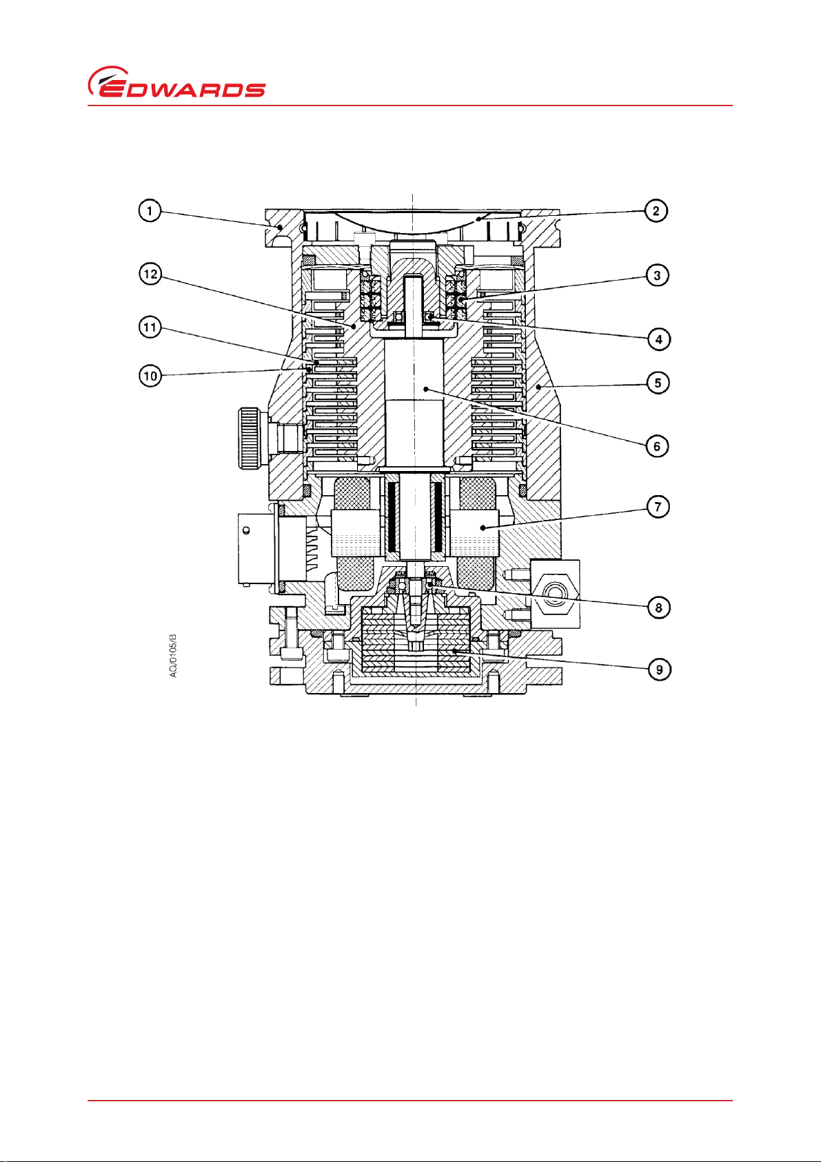
Figure 1 - Cross-section view of EXT70 Turbomolecular Pump
1. Inlet-flange
2. Inlet-screen
3. Magnetic bearing
4. Safety bearing
5. Envelope
6. Shaft
7. DC motor
8. Lower bearing
9. Oil reservoir
10.Spacer ring
11.Stator
12.R otor
B722-01-880 Issue K
Introduction
© Edwards Limited 2007. All rights reserved. Page 3
Edwards and the Edwards logo are trademarks of Edwards Limited.
Page 10
B722-01-880 Issue K
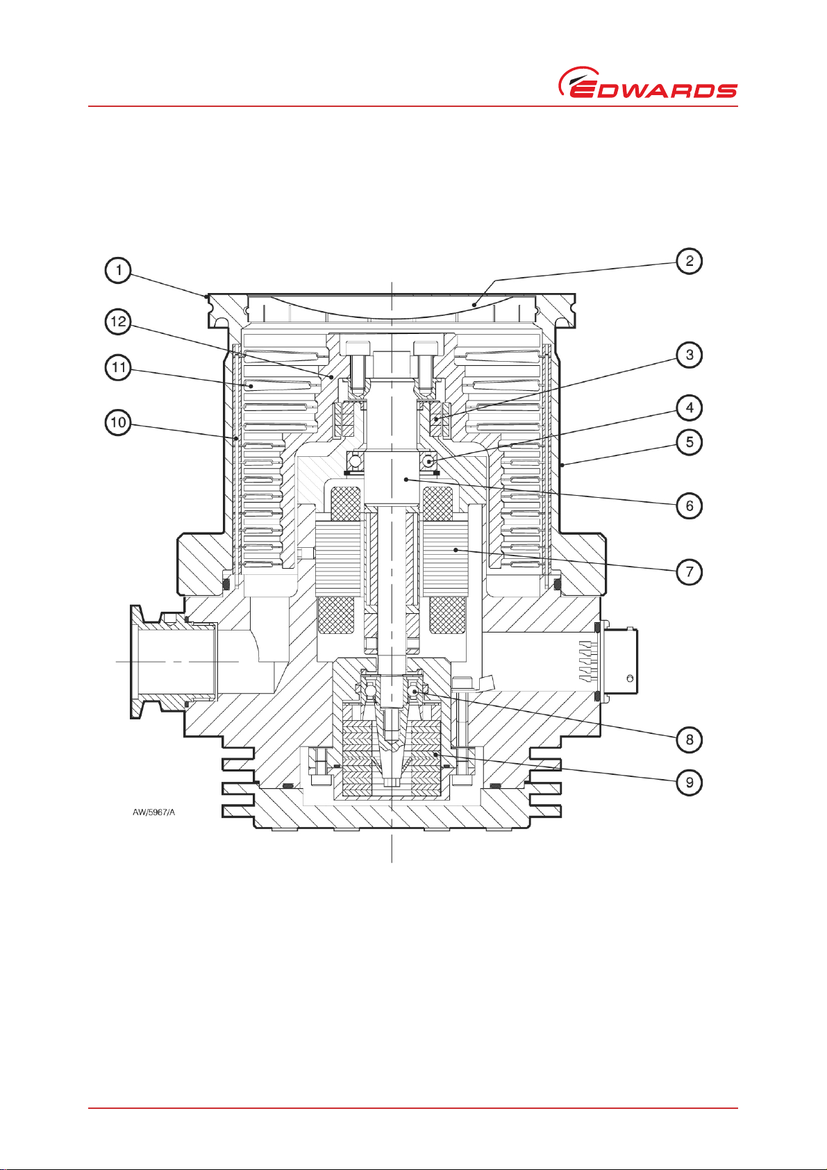
1. Inlet-flange
2. Inlet-screen
3. Magnetic bearing
4. Safety bearing
5. Envelope
6. Shaft
7. DC motor
8. Lower bearing
9. Oil reservoir
10.Spacer ring
11.Stator
12.Rotor
Introduction
Figure 2 - Cross-section view of EXT250 Turbomolecular Pump
Page 4 © Edwards Limited 2007. All rights reserved.
Edwards and the Edwards logo are trademarks of Edwards Limited.
Page 11

B722-01-880 Issue K
1.3 Vent options and vent control
To maintain the cleanliness of your vacuum system, we recommend that, whenever you switch the pump off, you
vent the pump (or vacuum system) when the speed of the EXT pump is between full rotational speed and 50% of full
rotational speed. At and above 50% of full rotational speed, the rotor spins fa st enough to suppress an y backstreaming
of hydrocarbon oil from your bac king pump.
However, if you vent the pump w hen it is at full rotational speed and the rate of pressure ri se is too high, the p ump
life may be reduced. We therefore recommend that you either limit the rate of pressure rise in accordance with
Figure 3, or only open the vent-valve after the EXT pump speed has fallen to 50% of full rotational speed.
The rate of pressure rise cannot be controlled by the manual vent-valve, so if you use the manual vent-valve, you
must only open the vent-valve after the EXT pump speed has fallen to 50% of f u ll rotational speed.
If you use a TAV5 vent-valve, but you cannot limit the rate of pressure rise, you must only open the vent-valve after
the EXT pump speed has fallen to 50% of full rotational speed. If you use the EXC Controller to control your TAV5
vent-valve, configure the Controller to select this option: refer to Section 3.4 for more information. The
EXC Controller is factory set to vent when the EXT pump is at 50% of full rotational speed after you have selected
Stop.
Introduction
© Edwards Limited 2007. All rights reserved. Page 5
Edwards and the Edwards logo are trademarks of Edwards Limited.
Page 12

B722-01-880 Issue K
This page has been intentionally left blank.
Page 6 © Edwards Limited 2007. All rights reserved.
Edwards and the Edwards logo are trademarks of Edwards Limited.
Page 13

2Technical data
2.1 Operating conditions
Table 1 - Operating conditions data
Maximum inlet flange temperature 100
Maximum magnetic field 5 mT
Ambient operating temperature
Water-cooling 5 to 40
Free convection cooling (EXT70 only) 0 to 30
Forced-air cooling 0 to 35
Maximum operating humidity
o
Ambient temperature up to 31
Ambient temperature up to 40 oC50%
Minimum backing pump displacement 0.6 m
Recommended backi n g pump
Operating attitude Vertical and upright through to horizontal
Maximum operating altitude 2000 m
Noise level (at 1 m) < 50 dB(A)
Installation category EN61010 part 1, Category 1
Pollution degree EN61010 part 1, Category 2
Equipment type Fixed Equipment, for indoor use only
*
A larger backing-pump may be required for maximum throughput.
C80%
*
o
C
o
C
o
C
o
C
3 h-1
(EXT70 DN40NW/DN50NW)
1.3 m3 h-1 (EXT70 DN63CF/DN63ISO-K)
4.6 m3 h-1 (EXT250 DN100CF/DN100ISO-K)
E2M0.7 (EXT70 DN40NW/DN50NW)
E2M1.5 (EXT70 DN63CF/DN63ISO-K)
E2M5 (EXT250 DN100CF/DN100ISO-K)
B722-01-880 Issue K
Technical data
2.2 Mechanical data
Table 2 - Mechanical data
Dimensions See Figure 4 and Figure 5
Inlet-flange: EXT70 DN40NW, DN50NW, DN63CF or DN63ISO-K
Inlet-flange: EXT250 DN100CF or DN100ISO-K
Outlet-flange DN16NW (EXT70), DN25NW (EXT250)
1
Vent-port
Purge-port (EXT250 only) DN10NW
Mass: EXT70 DN40NW/DN50NW 1.4 kg
EXT70 DN63CF 3.4 kg
EXT70 DN63ISO-K 1.5 kg
EXT250 DN100CF 5.6 kg
EXT250 DN100ISO-K 8.0 kg
© Edwards Limited 2007. All rights reserved. Page 7
Edwards and the Edwards logo are trademarks of Edwards Limited.
/8 inch BSP
Page 14

B722-01-880 Issue K
Technical data
2.3 Performance
Table 3 - EXT70 performance data
DN40NW DN50NW DN63CF DN63ISO-K
Pumping speed
Nitrogen 52 l s
Helium 53 l s
Hydrogen 46 l s
Compression ration
Nitrogen > 1 x 10
Helium 6000 6000 6000 6000
Hydrogen 500 500 500 500
Ultimate pressure
Maximum continuous inlet pressure
Water-cooling at 15 oC9 x 10
Air-cooling at 35 oC9 x 10
Free convection at 35
Nominal rotational speed 90000 r min
Standby rotational speed 63000 r min
Starting time to 90% speed
with EXC120/120E 90 sec 90 sec 90 sec 90 sec
with EXC300 90 sec 90 sec 90 sec 90 sec
Recommended Controller EXC100/120 EXC100/120 EXC100/120 EXC100/120
EXC120/E maximum input 250 VA 250 VA 250 VA 250 VA
EXC120/E normal power 60 VA 60 VA 60 VA 60 VA
Other compatible Controller EXC300 EXC300 EXC300 EXC300
EXC300 maximum input 480 VA 480 VA 480 VA 480 VA
EXC300 normal power 60 VA 60 VA 60 VA 60 VA
Quiescent power consumption 10 W 10 W 10 W 10 W
*
Pumping speeds are without inlet-screen. Inlet-screens are supplied fitted and reduce speed by
approximately 10%.
†
Ultimate pressure 48 hours after bakeout with 2-stage rotary vane backing-pump.
‡
Above this pressure, rotational speed drops below nominal.
*
-1
-1
-1
8
†
< 5 x 10
< 5 x 10
‡
9 x 10
-9
mbar < 5 x 10⁻⁹ mbar < 5 x 10
-7
Pa < 5 x 10⁻⁷ Pa < 5 x 10⁻⁸ Pa < 5 x 10⁻⁷ Pa
-1
mbar
1
Pa
-2
mbar
9 x 100 Pa
o
C9 x 10
-3
mbar
9 x 10⁻¹ Pa
-1
-1
-1
60 l s
-1
56 l s
-1
48 l s
> 1 x 10
9 x 10
9 x 10
8
-1
mbar
1
Pa
9 x 10⁻² mbar
9 x 100 Pa
9 x 10⁻³ mbar
9 x 10⁻¹ Pa
90000 r min
63000 r min
-1
65 l s
-1
60 l s
-1
50 l s
> 1 x 10
9 x 10
9 x 10
8
-10
mbar < 5 x 10⁻⁹ mbar
-1
mbar
1
Pa
9 x 10⁻² mbar
9 x 100 Pa
9 x 10⁻³ mbar
9 x 10⁻¹ Pa
-1
-1
90000 r min
63000 r min
-1
-1
-1
65 l s
-1
60 l s
-1
50 l s
> 1 x 10
9 x 10
9 x 10
8
-1
mbar
1
Pa
9 x 10⁻² mbar
9 x 100 Pa
9 x 10⁻³ mbar
9 x 10⁻¹ Pa
90000 r min
63000 r min
-1
-1
Page 8 © Edwards Limited 2007. All rights reserved.
Edwards and the Edwards logo are trademarks of Edwards Limited.
Page 15

B722-01-880 Issue K
Table 4 - EXT250 performance data
DN100CF DN100ISO-K
Pumping speed
Nitrogen 240 l s
Helium 250 l s
Hydrogen 190 l s
*
-1
-1
-1
240 l s
250 l s
190 l s
-1
-1
-1
Compression ration
Nitrogen > 1 x 10
Helium 2 x 10
8
4
> 1 x 10
2 x 10
8
4
Hydrogen 1500 1500
Ultimate pressure
†
< 5 x 10
-10
mbar < 5 x 10⁻⁹ mbar
< 5 x 10⁻⁸ Pa < 5 x 10⁻⁷ Pa
Maximum continuous inlet pressure
‡
Water -cooling at 1 5 oC
with EXC100/120 1 x 10⁻¹ mbar
1 x 101 Pa
-1
with EXC300 3 x 10
mbar
3 x 101 Pa
3 x 10
-2
mbar
0
Pa
-1
-1
Air-cooling at 35 oC3 x 10
Nominal rotational speed 60000 r min
Standby rotational speed 42000 r min
1 x 10⁻¹ mbar
1 x 101 Pa
3 x 10⁻¹ mbar
3 x 101 Pa
-2
3 x 10
3 x 10
mbar
0
Pa
60000 r min
42000 r min
-1
-1
Starting time to 90% speed
with EXC120/120E 100 sec 100 sec
with EXC300 90 sec 90 sec
Recommended Controller EXC100/120 EXC100/120
EXC120/E maximum input 250 VA 250 VA
EXC120/E normal power 60 VA 60 VA
Other compatible Controller EXC300 EXC300
EXC300 maximum input 480 VA 480 VA
EXC300 normal power 60 VA 60 VA
Quiescent power consumption 25 W 25 W
*
Pumping speeds are without inlet-screen. Inlet-screens are supplied fitted and reduce speed by approximately
10%.
†
Ultimate pressure 48 hours after bakeout with 2-stage rotary vane backing-pump.
‡
Above this pressure, rotational speed drops below nominal.
Technical data
© Edwards Limited 2007. All rights reserved. Page 9
Edwards and the Edwards logo are trademarks of Edwards Limited.
Page 16

B722-01-880 Issue K
CAUTION
CAUTION
WARNING
WARNING
Technical data
2.4 Pumping media
Vent dangerous gases and gas mixtures safely. Do not expose people to these gases.
Do not use EXT pumps to pump explosive gas mixtures as the pumps are not suitable for this
purpose.
Do not use an EXT to pump gases containing more than 20% oxygen unless the pump is gas purged. If you do, the
lubricant will polymerise and the pump will fail prematurely.
Do not use the EXT to pump mercury vapour and do not allow mercury (for example, from a Mcleod gauge) to
come into contact with the pump. If you do, the pump rotor may corrode and fail.
Note that concentrations of gases may be modified by the compression of the pump.
2.4.1 EXT70 and EXT250 pumps without gas purge
These pumps are designed to pump the following residual gases normally used in high-vacuum systems:
z Air z Carbon monoxide z Neon z Ethane z Methane
z Nitrogen z Krypton z Argon z Propane
z Carbon dioxide z Helium z Hydrogen z Butane
You can use the pumps to pump oxygen and water vapour, subject to the following conditions:
z Oxygen The oxygen concentration must be less than 20% by volume.
z Water vapour You must ensure that vapour does not condense inside the pump; refer to
Section 3.7.2.
If you wish to pump a gas not in the list above, co ntact your supplier for advice. If you do not contact your supplier,
you may invalidate the warranty on the pump. EXT70 and EXT250 pumps are not suitable for pumping aggressive or
corrosive gases.
2.4.2 EXT250 pumps with gas purge
When purged with an inert gas, EXT250 pumps can be used to pump oxygen in concentrations above 20% by volume.
Page 10 © Edwards Limited 2007. All rights reserved.
Edwards and the Edwards logo are trademarks of Edwards Limited.
Page 17

B722-01-880 Issue K
2.5 Vent gas specification and vent control data
Although the pump may be vented to atmospheric air, high relative humidity of the air may greatly increase the
subsequent pumping time. To reduce pump-down times vent the pump with dry, clean gases.
Table 5 - Vent gas data
Vent gas Dry air, nitrogen, argon or other inert gases
o
Maximum dew point at atmospheric pressure -22
Maximum size of particulates 1 μm
Maximum concentration of oil 0.1 parts per million
Maximum allowed rate of pressure rise See Figure 3
C
Technical data
Figure 3 - Maximum allowed rate of pressure rise during venting: system pressure
(Pa/mbar, with the backing pump i solated) against time (s), with the pump initially at full rotational speed
© Edwards Limited 2007. All rights reserved. Page 11
Edwards and the Edwards logo are trademarks of Edwards Limited.
Page 18

B722-01-880 Issue K
Technical data
2.6 Purge gas specification (for EXT250 only)
Table 6 - Purge gas data
Purge gas Dry nitrogen, argon or other inert gases
Maximum dew point at atmospheric pressure -22
Maximum size of particulates 1 μm
Maximum concentration of oil 0.1 parts per million
Allowable purge gas flow (when required) 20 to 100 sccm (0.33 to 1.67 mbar l s
Recommended purge gas flow 25 sccm (0.42 mbar l s
Maximum allowable purge gas supply pressure 2 bar gauge. 29 psig, 3 x 10⁵ Pa
2.7 Cooling-water
The following cooling-water specification corresponds to a typical high-quality drinking water specification. Check
with your water supply authority if you are in doubt about the quality of your supply.
Table 7 - Cooling-water data
o
C
33 to 167 Pa l s-1)
-1
, 42 Pa l s-1)
-1
,
Quality Mechanically clean and optically clear with no
deposits or turbidity
pH value 6.0 to 8.0
Maximum calcium carbonate concentration 75 parts per million
Maximum chloride concentration 100 parts per million
Maximum oxygen concentration 4 parts per million
o
Minimum water-cooling flow rate (at 15
Water temperature 10 to 20 oC
Maximum water pressure 5 bar gauge, 72 psig, 6 x 10
C) 15 l h
-1
5
Pa
Page 12 © Edwards Limited 2007. All rights reserved.
Edwards and the Edwards logo are trademarks of Edwards Limited.
Page 19

Figure 4 - EXT70 Turbomolecular Pump dimensions (mm)
1. Vent-valve
2. Earth (ground) screw
3. Backing-port
4. Allowance for right-angle cable connector
5. Cooling-water connectors
6. Electrical supply connector
B722-01-880 Issue K
Technical data
© Edwards Limited 2007. All rights reserved. Page 13
Edwards and the Edwards logo are trademarks of Edwards Limited.
Page 20

B722-01-880 Issue K
1. Purge plug in purge-port
2. Vent-valve
3. Earth (ground) screw
4. Electrical supply connector
5. Cooling-water connectors
6. Allowance for right-angle cable connector
7. Backing-port
Technical data
Figure 5 - EXT250 Turbomolecular Pump dimensions (mm)
Page 14 © Edwards Limited 2007. All rights reserved.
Edwards and the Edwards logo are trademarks of Edwards Limited.
Page 21

B722-01-880 Issue K
WARNING
3 Installation
Safely route all vacuum, vent/purge gas and cooling-water pipelines, and all electrical cables and
wires, so that people cannot trip over them.
3.1 Unpack and inspect
The pump is packed to prevent damage in transit. Take care when you unpack the pump to avoid excessive shocks
which could damage the bearings and reduce the life of the pump. The pump is supplied with the inlet and outlet
sealed to prevent entry of dust and vapour. Do not remove these seals until you are ready to install the pump on your
vacuum system.
Remove all packing materials and check the pump. If the pump is damaged, notify your supplier and the carrier in
writing within three days; state the Item Number of the pump together with your order number and your supplier’s
invoice number. Retain all packing materials for inspection. Do not use the pump if it is damaged.
Check that your package contains the items listed in Table 8. If any of these items is missing, notify your supplie r in
writing within three days.
Table 8 - Checklist of items
Installation
Quantity Description Check (3)
1 Turbomolecular pump
1 Inlet seal or compression gasket
If the pump is not to be used immediately, store the pump in suitable conditions, as described in Section 6.1.
Do not discard the packing materials; retain them to repack the pump when you return it for service.
3.2 Typical installation
A typical pumping system with an EXT pump is shown in Figure 6. When necessary, purge the EXT pump with inert
gas as described in Section 3.5.
The accessories available for these EXT pumps are detailed in Section 7.4; the accessories are shown in Figure 8.
© Edwards Limited 2007. All rights reserved. Page 15
Edwards and the Edwards logo are trademarks of Edwards Limited.
Page 22

B722-01-880 Issue K
1. Alternative position
for vent-valve
2. Vacuum system
3. High-vacuum gauge
4. Inlet-screen
5. EXT pump
6. Backing valve
7. Vacuum gauge
8. Flexible bellows
9. Foreline trap
10.Rotary backing pump
11.Mist filter
12.Cooling water connectors
13.EXC Controller
14.Air-cooler
15.PRX10 purge restrictor
16.Regulated purge gas supply
17.Vent-valve
Installation
Figure 6 - Typical pumping system
Page 16 © Edwards Limited 2007. All rights reserved.
Edwards and the Edwards logo are trademarks of Edwards Limited.
Page 23

B722-01-880 Issue K
WARNING
WARNING
1. EXT inlet-flange
2. Inlet-screen
3.3 Connect to the vacuum system
Install the pump in the vacuum system before you connect the EXC Controller. This will ensure that
the pump cannot operate and injure people during installation.
3.3.1 Inlet-screen
Do not remove the inlet-screen unless you can be sure that there is no danger that debris can fall into the pump. In
order to avoid the danger of injury from the rotor blades, do not remove the inlet-screen until you are ready to mount
the pump onto your system. If the screen is removed, the pumping speed will increase by approximately 10%. It is
not possible to remove the inlet-screen from a pump with an NW inlet-flange.
To remove the inlet-screen from pumps with ISO or CF flanges, carefully extract it from the inlet-flange using a ben t
wire hook. To replace a screen which has been removed, install it as shown in Figure 7, with the Edwards logo
uppermost. Ensure that the dimples on the rim of the screen engage in the groove in the pump flange. If necessary,
gently bend the tags of the screen outwards to ensure a tight fit.
Figure 7 - Correct installation of the inlet-screen
Installation
3.3.2 Mechanical fixing
Do not operate the EXT pump until it is securely fixed. If the pump seizes, the stored energy of the
rotor can cause rapid movement of the pump, which may cause damage and injury to people.
There are two ways in which the EXT pump can be securely fixed. Ideally, the EXT pump should be securely fixed by
its inlet-flange to a rigid, firmly fixed vacuum system: see Section 3.3.4. If this is not possible because of the nature
of the vacuum system, the base of the EXT pump must be securely fixed to a firm support: see Section 3.3.3.
© Edwards Limited 2007. All rights reserved. Page 17
Edwards and the Edwards logo are trademarks of Edwards Limited.
Page 24

B722-01-880 Issue K
Installation
3.3.3 Base mounting
Ensure that the base of th e pump is securely fixed to a fi rm support (refer to Figure 4 and Figure 5 for the fixing hole
details). If the pump supports the weight of the vacuum system, the mass of the vacuum system must be no m ore
than 10 kg for an EXT70 pump, or no more than 20 kg for an EXT250 pump.
You must also ensure that your mounting method meets the following requirements, so that the EXT pump will remain
secure in the event of a pump seizure:
z The support mounting must be able to withstand a destructive torque of 333 Nm for an EXT70 pump or
620 Nm for an EXT250 pump.
z Fit cap-head fixing screws through the tapped fixing-holes in the base of the pump (see Figure 4 and
Figure 5): use M4 screws for an EXT70 pump, and use M5 screws for an EXT250 pump.
z The fixing screws must comply with ISO 898-1, with a strength class of 12.9 (nominal tensile strength
1200 MPa).
z The fixing screw engagement length must be 6 mm or more.
z Tighten the fixing screws to a torque of 6 Nm (0.61 kgf m) on EXT70 pumps, and to a torque of 12 Nm
(1.22 kgf m) on EXT250 pumps.
3.3.4 Inlet connection and orientation
The EXT pump can be fixed to the vacuum system by the inlet-flange. The pump can be mounted in any attitude from
vertical and upright through to horizontal (±2o). If the pump is mounted horizontally and you use a rotary vane pump
to back the EXT pump, the backing port must point vertically downwards (±20o) to reduce the risk of contamination
from the backing pump oil.
Make sure that the pump-inlet and all components fitted to the p ump-inlet are clean and dust-free. If the pump-inle t
is not kept clean, the pump-down time may be increased.
z The inlet-connection of the EXT pump is a CF flange, an ISO flange or an NW flange.
z If the pump has a CF flange, use the copper compression gasket supplied with the pump and use a full
complement of bolts to connect the inlet-flange of the pump to the vacuum system.
z If the pump has an ISO flange, use the Edwards trapped ‘O’ ring supplied with the pump and use a minimum
of four claw clamps to connect the inlet-flange of the pump to the vacuum system. Ensure that each claw
clamp is tightened to a torque of 10 Nm or more.
Alternatively, use a rotatable collar and the trapped ‘O’ ring supplied with the pump to connect the inletflange of the pump to the vacuum system; use a full complement of bolts with the rotatable collar.
z If the pump has an NW flange, use the Co-Seal supplied with the pump and a suitable NW clamp to connect
the inlet-flange of the pump to the vacuum system.
Ensure that no torque or other forces are transmitted to the pump from the vacuum system or the associated
pipelines.
If necessary, fit an inlet vibration isolator between the pump-inlet and the vacuum system: refer to Section 7.4.8 for
the Item Numbers, and refer to the instruction manual s upplied with the vibration isolator for installation details. If
you fit a vibration isolator, you must securely fix the base of the EXT pump as described in Section 3.3.3.
Note: The first time you pump down the syst em to vacuum , you must re-tighten the bolts which se cure the inlet-
flange.
Page 18 © Edwards Limited 2007. All rights reserved.
Edwards and the Edwards logo are trademarks of Edwards Limited.
Page 25

B722-01-880 Issue K
3.3.5 Backing connection
Use suitable vacuum tubing and connectors to connect the NW flange of the backing-port to your backing-pump. If
necessary, use flexible pipe or bellows to reduce the transmission of vibration from the backing-pump to the EXT
pump.
We recommend that you use an Edwards two-stage backing-pump. The backing-pump can also be controlled by the
EXC Controller. The minimum size of the backing-pump required is given in Table 1. You may have to use a larger
backing-pump if you run the pump at a high inlet pressure or high throughput or if you purge the pump with more
than 25 sccm (0.42 mbar l s-1, 42 Pa l s-1) of purge gas.
Do not use the EXT pump with a backing pressure below 1 x 10
increase the evaporation rate of the lubricating oil and so will reduce the life of the bearings.
-4
mbar (1 x 10⁻² Pa). Lower backing pressures will
3.4 Vent-valve connection and control
When you design your system and when you install a vent-valve, take note of the information in Section 1.3 and in
Section 2.5. You can vent the EXT pump and your vacuum system by any of the following methods:
z Use the manual vent-valve supplied.
z Use a T A V5 solenoid vent-valve accessory (see Section 7.4.6) in place of the manual vent-valve, together with
a vent-restrictor, if necessary.
Installation
z Use a TAV5 vent-valve connected to a convenient flange on your vacuum system, with a vent-restrictor, if
necessary.
z Use an alternative valve connected to your vacuum system, together with a vent-restrictor, if necessary.
If you use the manual vent-valve, you must open the vent-valve only after the EXT pump speed has fallen to 50% of
full rotational speed.
If you use the TAV5 vent-valve, you can only vent the EXT pump when it is at full speed if the vacuum system has a
volume of 5 litres or more. If the volume of your vacuum system is less than 5 litres, you can incorporate a suitable
restrictor (see Table 9) and vent the pump when it is at full speed. Alternatively, if you do not fit a restrictor, you
can use the EXC Controller to control the vent-valve and configure the EXC Controller to open the vent-valve after
the EXT pump speed has fallen to 50% of full rotational speed: do not select the ‘Vent On Stop’ option (refer to the
EXC Controller instruction manual for more information).
If you use another vent-valve, you must ensure that you have a suitable vent-restrictor fitted to suit your vacuum
system to limit the rate of pressure rise: refer to Table 9. If you do not have a suitable vent-restrictor fitted, you
must open the vent-valve only after the speed of the EXT pump has fallen to 50% of full rotational speed.
If you connect the vent-valve to your vacuum system, select a point upstream of the EXT pump to prevent
backstreaming of oil from the backing pump. Do not connect the vent-valve to the backing pipeline. Connect the
inlet of the vent-valve to the vent gas supply (refer to Section 2.5 for the vent gas specification).
Note: If you use a vent-restrictor, you may find that the time required to vent your system is unacceptably long.
You may be able to reduce the vent time if you use an unrestricted vent port without a vent-restrictor and
wait until the pump speed has fallen to 50% of full rotational speed before you vent the pump.
Table 9 - Vent-valve orifice diameter (with atmospheric pressure at the inlet of the vent-valve)
Vacuum system volume (l) Orifice diameter (mm)
< 20
< 10
< 5
< 2.5
< 1.25
© Edwards Limited 2007. All rights reserved. Page 19
Edwards and the Edwards logo are trademarks of Edwards Limited.
≤ 1.0
≤ 0.7
≤ 0.5
≤ 0.35
≤ 0.25
Page 26

B722-01-880 Issue K
CAUTION
WARNING
Installation
3.5 Purge gas connection (EXT250 only)
3.5.1 Connect the purge gas
If you want to supply a purge gas to the pump, remove the purge plug from the purge-port, fit a vent port adaptor
(see Section 7.4.6) to the purge-port, then connect your purge gas supply to the vent port adaptor. Your purge gas
must comply with the specification given in Section 2.6.
You must limit the flow rate of the purge gas to the allowed range, also specified in Section 2.6. To limit the flow
rate, use a flow controller or a pressure regulator and calibrated flow restrictor.
The PRX10 purge restrictor accessory (see Section 7.4.9) is suitable for this purpose. Adjustment of the PRX10 is
described in the instruction manual supplied with the accessory.
3.5.2 Recommended purge gas flow
The recommended purge gas flow for typical applications is 25 sccm (0.42 mbar l s-1, 42 Pa l s-1). This flow will protect
the pump when you pump oxygen in concentrations above 20% by volume.
3.6 Electrical installation
You must electrically bond the EXT pump to earth (ground): use the earth (ground) screw provided
on the pump (Figure 4, item 2 and Figure 5, item 3).
Always make the electrical connections to the EXT pump after the pump has been installed on your vacuum system.
The EXC Controller provides the electrical supply to the EXT pump through the multiway pump-to-controller cable.
Connect and lock the bayonet-connectors at the ends of the cable to the mating connectors on the pump and the
EXC Controller.
The EXC Controller is designed to allow a pumping system to be configured in a variety of ways, from a basic
manually-operated system to a fully automatic system with remote control. Refer to the instruction manual supplied
with the EXC Controller to complete the electrical installation.
3.7 Cooling
When you bake the EXT pump to above 70 oC at the inlet-flange, you must cool the pump by forced-air or watercooling to prevent damage to the bearing lubricant.
Page 20 © Edwards Limited 2007. All rights reserved.
Edwards and the Edwards logo are trademarks of Edwards Limited.
Page 27

B722-01-880 Issue K
3.7.1 Cooling methods
We recommend that, whenever possible, you cool the EXT pump by forced-air or water-cooling, however if necessary
you can use natural convection to cool the EXT70 in certain applications. Table 10 shows the acceptable cooling
methods which you can use for different applications.
If you use natural convection or forced-air to cool the pump, you must ensure that there is an adequate supply of
cooling-air to the pump.
Table 10 - Pump cooling methods for different applications
Installation
Application conditions
o
Ambient temperature < 30
inlet-flange temperature < 70 oC
Ambient temperature 30 to 35 oC or inlet-flange
temperature > 70
During bakeout band operation,
light pumping duty
With continuous high gas throughput Forced-air or
When the EXT pump is cycled repeatedly from atmospheric
to ultimate pressure
Combinations of high ambient temperature, bakeout band
operation, high gas throughput and repeatedly cycled
operation
o
C, light pumping duty
C, light pumping duty with
EXT70 EXT250
Natural convection,
forced-air or water-cooling
Forced-air or
water-cooling
Forced-air or
water-cooling
water-cooling
Forced-air or
water-cooling
Water-cooling Water-cooling
Cooling method
Forced-air or
water-cooling
Forced-air or
water-cooling
Forced-air or
water-cooling
Forced-air or
water-cooling
Forced-air or
water-cooling
3.7.2 Forced-air cooling
An air-cooler accessory is available for the EXT pumps (refer to Section 7.4.7). Fit the air-cooler as described in the
instruction manual supplied with it. If you wish to use an alternative fan for ai r-cooling, ensure that the flow rate is
above 40 m3 h-1 (25 cfm) for the EXT70, and above 70 m3 h-1 (40 cfm) for the EXT250.
3.7.3 Water-cooling
The cooling-water supply must comply with the specification given in Section 2.7. Pipes in the water-cooling circuit
may become blocked if the cooling-water contains too much calcium carbonate or if it contains particulates which
are too large. Corrosion of the water-cooling circuit may occur if there is too little calcium carbonate and oxygen in
the water. Good quality drinking water is usually suitable for water-cooling. If in doubt, you must check the quality
of your cooling-water supply and, if necessary, provide treatment and filtration.
Connect the cooling-water sup ply t o the wa te r-cool er as d escr ibed be low . Ei ther of the t wo ri ffled hose co nnecto rs
on the water-cooler can be used for the water supply or return connections.
1. Push reinforced hose (approximately 6 mm internal diameter) over the ends of the riffled hose connectors on
the water-cooler.
2. Attach the hose with strong hose clips and make sure that they are tightened securely.
1
Alternatively, unscrew the riffled hose connectors and make direct connections to the
fittings.
You must turn off the cooling-water supply when you switch off the pump to prevent condensation of vapours inside
the pump. The EXC Controller can operate a solenoid-valve for this purpose.
When you remove the EXT pump for maintenance or when you replace the EXT pump, you can unscrew the two M4
cap-head fixing-screws to remove the water-cooler from the pump; you do not have to break the cooling-water
circuit. Make sure that there is a layer of thermal contact grease on the w ater-cooler before you fit it to the pump.
© Edwards Limited 2007. All rights reserved. Page 21
Edwards and the Edwards logo are trademarks of Edwards Limited.
/8 BSP female threaded
Page 28

B722-01-880 Issue K
This page has been intentionally left blank.
Page 22 © Edwards Limited 2007. All rights reserved.
Edwards and the Edwards logo are trademarks of Edwards Limited.
Page 29

B722-01-880 Issue K
WARNING
WARNING
4 Operation
Do not disconnect the pump-to-controller cable when the EXT pump is operating. If you do, there
may be a risk of injury or death by electric shock.
Do not expose any part of your body to vacuum. If you do, you may be injured.
4.1 Start-up
Use the procedure below to start up a basic, manually-controlled pumping system with a manual vent-valve and an
EXC Controller. Refer to the EXC Controller instruction manual where the backing-pump and accessories are
automatically controlled by the EXC Controller.
1. Turn the manual vent-valve clockwise to close it.
Operation
2. Turn on the cooling-water supply (if water-cooling is used).
3. Start the backing-pump.
4. When the vacuum system pressure is approximately 1 mbar (1 x 10
the EXC Controller to start the EXT pump.
5. The pump will then accelerate to full operating speed. When this has been reached, the upper LED of the speed
indicator on the front panel of the EXC Controller will light.
Note: The first time you pump down the syst em to vacuum , you must re-tighten the bolts which se cure the inlet-
flange: refer to Section 3.3.4.
2
Pa) or less, press the Start/Stop button on
4.2 Stand-by
You can press the Standby button on the EXC Controller to operate the EXT pump at reduced rotational speed. Select
Standby before or after Start-up, for any of the following reasons:
z To extend pump-bearing life and still maintain adeq uate vacuum pumping performance (for example, when
you leave a system under vacuum over holiday periods)
z To increase system pressure or to extend the maximum inlet pressure range of the pump where this suits a
particular process
z To avoid pump excitation of any resonances which may exist on sensitive instrumentation.
© Edwards Limited 2007. All rights reserved. Page 23
Edwards and the Edwards logo are trademarks of Edwards Limited.
Page 30

B722-01-880 Issue K
CAUTION
Operation
4.3 Shut-down
Note: In an emergency only, open the vent-valve quickly to decelerate the pump rotor in the shortest possible
time.
Use the procedure below to shut down a basic, manually-controlled pumping system with a manual vent-valve and
an EXC Controller. Refer to the EXC Controller instruction manual where the backing-pump and accessories are
automatically controlled by the EXC Controller.
1. Switch off the backing-pump and press the Start/Stop button on the EXC Controller to switch off the EXT pump.
2. When the EXT pump rotational speed has fallen to below 50% of full rotational speed, turn the manual
vent-valve anticlockwise to open it. Ensure that the rate of pressure rise does not exceed the allowed rate of
pressure rise, otherwise you can damage the pump: refer to Section 1.3 and to Section 2.5.
3. If water-cooling is in use, turn off the cooling-water supply.
4.4 Safety interlocks and control system
The pump protection and safety interlock features are listed below. Refer to the instruction manual supplied with
the EXC Controller for a full description of these features:
z The EXC Controller monitors the temperature of the EXT pump and the electrical power consumption of the
pump. If the EXC Controller detects excessive power consumption or temperature, the rotational speed of
the pump motor is reduced until the power and temperature return to normal
z If the rotational speed is reduced to 50% of nominal speed, then the pu mp is stopped immed iately (or after a
user defined time delay) and the Fail LED on the EXC Controller lights
z If pump rotational overspeed is detected by the EXC Controller, the pump is stopped immediately and the
FAIL LED on the EXC Controller lights.
If the Fail LED lights, switch off the backing-pump immediately and vent the EXT pump. Once the EXT pump has
stopped, rectify the cause of the failure (refer to Section 5.5), press the EXC Controller Start/Stop button to reset
the Fail condition, and restart the EXT pump. If the pump is ho t, allow sufficient time for it to cool before you restart
it.
4.5 Bakeout
When you bake the EXT pump to above 70 oC at the inlet-flange, you must cool the pump by forced-air or watercooling, to prevent damage to the bearing lubricant.
If you heat your EXT pump (and your vacuum system), you will speed up the degassing process so that the pu mp will
reach ultimate vacuum in the shortest possible time. If y ou heat the pump, this will also prevent condensation of
vapours inside the pump.
You can use the Edwards BX bakeout band to heat the pump (refer to Section 7.4.4). Fit the band around the pump,
just below the inlet-flange. When you bake the pump or the system, make sure that the temperature of the inletflange does not exceed 100 oC.
o
If you bake your vacuum system and the temperature of the system exceeds 200
between the system and the EXT pump. This radiation shield will reduce the heat radiated onto the pump rotor.
Typically, a bakeout of four hours is long enough to remove water condensation from the pump. However, the
bakeout time will depend on the amount of condensation in the pump and the vacuum system, and the ultimate
pressure you want to achieve.
Page 24 © Edwards Limited 2007. All rights reserved.
Edwards and the Edwards logo are trademarks of Edwards Limited.
C, you must put a radiation shield
Page 31

B722-01-880 Issue K
CAUTION
WARNING
WARNING
5Maintenance
Disconnect the pump from the EXC Controller before you remove the pump from your vacuum
system for maintenance or fault-finding procedures.
5.1 Introduction
The maintenance operations for the EXT Turbomolecular pumps are described in t he following sections. The ISX inletscreen, the WCX water-cooler and inlet-flange seals are available as spares (refer to Section 7.3); fit these spares as
described in Section 3.
5.2 Bearing life
When supplied, the pump contains sufficient lubricant to supply the bearings for life. No routine maintenance is
therefore required between bearing replacements. The bearings are not user-serviceable. The bearings will need to
be replaced when they reach the end of their service life. This is typically more than 20,000 hours, but may be less
depending upon the type of pumping duty on which the pump was used.
Maintenance
When the bearings need replacement, we recommend that you exchange your pump for a factory reconditioned
replacement. Alternatively, you can send your pump to an Edwards Service Centre to have the bearings replaced.
When you return EXT pumps to Edwards Service Centres please obey the procedure included at the end of this
manual. However, the instruction to drain all fluids does not apply to the lubricant in the EXT pump oil-reservoirs.
5.3 Rotor life
The life of the EXT pump rotor is typically 40,000 to 50,000 cycles (of acceleration to full speed, and then
deceleration to a stop). The pump rotor is not user-serviceable.
We therefore recommend that you exchange your pump for a factory reconditioned replacement every 20,000 cycles,
or 10 years of use, whichever occurs first. Alternatively, you can send your pump to an Edwards Service Centre for a
major service (which will include rotor replacement).
When you return EXT pumps to Edwards Service Centres please obey the procedure included at the end of this
manual. However, the instruction to drain all fluids does not apply to the lubricant in the EXT pump oil-reservoirs.
5.4 Clean the pump
Clean the external surfaces of the EXT pump in a well-ventilated location. When you use cleaning
solutions and solvents to clean the pump, observe all precautions specified by the manufacturer.
Avoid inhalation of any particulates which may be present in the pump.
Do not attempt to clean any parts of the EXT pump other than the external surfaces. Organic solvents may
damage internal pump components. Do not use abrasive materials to clean any part of the pump.
© Edwards Limited 2007. All rights reserved. Page 25
Edwards and the Edwards logo are trademarks of Edwards Limited.
Page 32

B722-01-880 Issue K
Maintenance
If the inside of the EXT pump is contaminated, it may not be possible to achieve the specified ultimate vacuum, or
pump-down time may increase. In these circumstances, you should return the pump to an Edwards Service Centre,
where the pump will be dismantled and cleaned. Use the procedure given in the forms at the end of this manual to
return the pump.
You can use any organic solvent to clean the external surfaces of the EXT pump. We recommend that you use non CFC solvents, such as isopropanol or ethanol. Use a cleaning solution which is suitable for the contaminants on the
pump surfaces.
For environmental reasons, keep wastage of cleaning solutions and solvents to a minimum.
5.5 Fault finding
Table 11 - Fault finding
Symptom Check Action
The pump does not rotate.
After pressing start - Fail LED
not lit.
Is the EXC Controller power
LED lit?
Is the EXC Controller Start/
Stop LED flashing?
If not, check that the electrical supply is on, check
that the switch at the rear of the EXC Controller is
on, check the fuse in the rear of the EXC Controller.
If all of the above are OK then the EXC Controller is
faulty. Consult Edwards or your supplier.
If so, check that the correct links are made on the
EXC Controller logic interface (refer to the
instruction manual supplied with the
EXC Controller).
The EXC Controller trips into
Fail - at any speed.
The EXC Controller trips into
Fail during the ramp-up and
before 50% speed is reached.
Check that any system interlocks are correctly made
(refer to the instruction manual supplied with the
EXC Controller).
Check that the pump-to-controller cable is
connected.
If all of the above are OK then consult Edwards or
your supplier.
Is the EXC Controller first
speed indication LED lit?
Are the system interlocks
correctly connected?
Is the inlet pressure too
high?
Is the EXT pump running too
hot?
Does the rotor rotate freely? If not, the EXT pump-bearings are damaged. Consult
None of the above. Increase the timer setting (refer to the instruction
If not, the EXC Controller is faulty. If lit, then the
EXT pump is faulty. Consult Edwards or your
supplier.
Ensure that the system interlocks do not open after
the EXT pump has started.
If so, reduce the pumping load, or check for a gross
leak into the system.
Increase the cooling-water flow or decrease the
water temperature or do both. You may need to
change from air-cooling to water-cooling. (Refer to
Section 2 for maximum inlet pressure and cooling
requirements). Check that external heat sources
(such as system bakeout heaters) are not excessive.
Edwards or your supplier.
manual supplied with the EXC Controller). If the
EXC Controller still trips into Fail consult Edwards or
your supplier.
Page 26 © Edwards Limited 2007. All rights reserved.
Edwards and the Edwards logo are trademarks of Edwards Limited.
Page 33

Table 11 - Fault finding (continued)
Symptom Check Action
The EXC Controller trips into
Fail after 50% speed has been
reached - the first two speed
LEDs are lit.
The EXC Controller trips into
Fail - all the speed LEDs are
lit.
Ultimate pressure cannot be
reached.
The EXT is very noisy or there
is excessive vibration or both.
Is the pressure too high? If so, reduce the pumping load or check for a gross
leak into the system.
If the high gas load is temporary, configure the
EXC Controller to delay the Fail trip on 50% speed
and set an appropriate delay time (refer to the
instruction manual supplied with the
EXC Controller).
Is the EXT pump running too
hot?
Does the EXT pump rotor
rotate freely?
- Consult Edwards or your supplier.
Is the pressure limited by
water vapour?
Are any of the vacuum
gauges contaminated?
Is the pumping speed
insufficient (due to poor
conductance between the
pump and the gauge or too
large a chamber)?
Is the backing pressure
< 0.2 mbar (20 Pa)?
Is the high-vacuum area of
the system contaminated?
Check the rest of your
system for leaks and
contamination.
Remove th e pump from the
system and test the ultimate
pressure of the pump alone
(see Section 2 for
specification).
Is the pump rotational speed
the same as the resonant
frequency of the attached
system?
Is the vibration being
transmitted from the rotary
pump?
Is the noise irregular and
getting progressively worse?
Is the EXT making a constant
high-pitched noise?
Increase the cooling-water flow or decrease the
water temperature or do both. You may need to
change from air-cooling to water-cooling.
If not, the EXT pump-bearings are damaged. Consult
Edwards or your supplier.
Bake the system and pump.
If so, clean or replace them.
Increase the conductance or reduce the volume.
If not, check for backing line leaks. If the
throughput is high, you may need a larger backingpump.
If so, clean the high-vacuum system.
If found, clean the contaminated areas and repair
the leaks.
If poor, check the pump for contamination and if
necessary return the pump as described in
Section 5.4. Leak-check the pump. If the leak rate
>1 x 10
or your supplier.
If so, change the natural frequency of your system
or isolate the pump using flexible bellows.
If so, fit flexible bellows or a vibration isolator in
the backing line.
If so, a bearing is defective. Consult Edwards or your
supplier.
If so, the rotor is out of balance. Consult Edwards or
your supplier.
B722-01-880 Issue K
-7
mbar l s-1 (1 x 10⁻⁵ Pa l s-1) consult Edwards
Maintenance
© Edwards Limited 2007. All rights reserved. Page 27
Edwards and the Edwards logo are trademarks of Edwards Limited.
Page 34

B722-01-880 Issue K
This page has been intentionally left blank.
Page 28 © Edwards Limited 2007. All rights reserved.
Edwards and the Edwards logo are trademarks of Edwards Limited.
Page 35

B722-01-880 Issue K
6 Storage and Disposal
6.1 Storage
Use the following procedure to store the pump:
1. Place protective covers over the inlet, outlet, purge and vent ports.
2. Place the pump in its packing materials. For fastest pump-down when the pump is put back into service, seal the
pump inside a plastic bag together with a suitable desiccant.
3. Store the pump in cool, dry conditions until required for use. When required, prepare and install the pump as
described in Section 3.
4. Keep the pump upright at all times to prevent the drainage of oil from the bearing reservoir.
5. Avoid long-term storage if possible. When long-term storage is ne cessary, the pump should be set up and run for
at least eight hours every six months.
6.2 Disposal
Storage and Disposal
Dispose of the EXT Turbomolecular Pump and any comp onents and accessories safely in accordance with all local and
national safety and environmental requirements.
Take particular care with any components which have been contaminated with dangerous process substances.
© Edwards Limited 2007. All rights reserved. Page 29
Edwards and the Edwards logo are trademarks of Edwards Limited.
Page 36

B722-01-880 Issue K
This page has been intentionally left blank.
Page 30 © Edwards Limited 2007. All rights reserved.
Edwards and the Edwards logo are trademarks of Edwards Limited.
Page 37

B722-01-880 Issue K
7 Service, Spares and Accessories
7.1 Introduction
Edwards products, spares and accessories are available from Edwards companies in Belgium, Brazil, China, France,
Germany, Israel, Italy, Japan, Korea, Singapore, United Kingdom, U.S.A and a world-wide network of distributors.
The majority of these centres employ Service Engineers who have undergone comprehensive Edwards training
courses.
Order spare parts and accessories from your nearest Edwards company or distributor. When you order, state for each
part required:
z Model and Item Number of your equipment
z Serial number
z Item Number and description of part.
7.2 Service
Edwards products are supported by a world-wide network of Edwards Service Centres. Each Service Centre offers a
wide range of options including: equipment decontamination; service exchange; repair; rebuild and testing to factory
specifications. Equipment which has been serviced, repaired or rebuilt is returned with a full warranty.
Service, Spares and Accessories
Your local Service Centre can also provide Edwards engineers to support on-site maintenance, service or repair of
your equipment.
For more information about service options, contact your nearest Service Centre or other Edwards company.
7.3 Spares
7.3.1 ISX inlet-screen
An inlet-screen is fitted to your pump as supplied to prevent damage from the entry of debris into the pump. The
Item Numbers of replacement inlet-screens are given below. Select the inlet-screen according to the pump inletflange size. You cannot replace the inlet-screen on an EXT70 pump with an NW inlet-flange.
Flange size Inlet-screen Item Number
DN63ISO-K/DN63CF ISX63 B580-51-005
DN100ISO-K/DN100CF ISX100 B580-51-001
7.3.2 WCX water-cooler
A water-cooler can be fitted to the EXT pump. Please refer to Section 3 to check the suitability of water cooling for
a particular application. Pumps with a Conflat flange are supplied with a water-cooler.
Pump Water-cooler Item Number
EXT70/EXT250 ISX63 B736-00-121
© Edwards Limited 2007. All rights reserved. Page 31
Edwards and the Edwards logo are trademarks of Edwards Limited.
Page 38

B722-01-880 Issue K
Service, Spares and Accessories
7.3.3 Inlet-flange seals
EXT pumps are supplied with a seal to match the inlet-flange. The Item Numbers of replacement seals are listed
below.
Flange size Inlet seal Item Number
DN63ISO-K ISO63 trapped ‘O’ ring, fluoroelastomer B271-58-170
DN40NW DN40NW Co-Seal, fluoroelastomer B271-58-453
DN50NW DN50NW Co-Seal, fluoroelastomer B271-58-466
DN100ISO-K ISO100 trapped ‘O’ ring, fluoroelastomer B271-58-171
DN100CF 100CF Copper gasket (pack of 5) C082-00-003
DN63CF 63CF Copper gasket (pack of 5) C081-00-003
7.4 Accessories
7.4.1 Installation
The accessories available for use with the EXT turbomolecular pumps are described in the following Sections. Figure 8
shows how the accessories are fitted to an EXT pump.
7.4.2 EXC Controller
The Edwards EXC Controllers provide the facilities necessary for operating a pumping system based on an EXT pump.
The following EXC Controllers are available:
Controller Voltage Item Number
EXC120 100-240 V D396-16-000
EXC100 100-240 V D396-20-000
EXC300 100-120/200-240 V D396-14-000
7.4.3 Pump-to-controller cable
A pump-to-controller cable must be used with each pump. It is not supplied with the EXT Pump or the EXC Controller.
The following cables are available:
Cable Length Item Number
Pump-to-controller cable 1 m D396-18-010
Pump-to-controller cable 3 m D396-18-030
Pump-to-controller cable 5 m D396-18-050
Page 32 © Edwards Limited 2007. All rights reserved.
Edwards and the Edwards logo are trademarks of Edwards Limited.
Page 39

Figure 8 - Installation of optional accessories (and spares)
B722-01-880 Issue K
Service, Spares and Accessories
1. Vibration isolator
2. Bakeout band
3. Inlet-flange seal (supplied)
4. EXT pump
5. Solenoid vent-valve
6. DN10NW adaptor
*
The design of the air-cooler varies according to pump model.
© Edwards Limited 2007. All rights reserved. Page 33
Edwards and the Edwards logo are trademarks of Edwards Limited.
7. Manual vent-valve (supplied)
8. Vent-port
9. Water-cooler
10.Purge-port
11.Air-cooler
*
12.Purge plug (supplied)
13.DN10NW adaptor
14.Purge restrictor
15.Bakeout band position
16.Inlet-screen (supplied)
Page 40

B722-01-880 Issue K
Service, Spares and Accessories
7.4.4 BX bakeout band
A BX bakeout band accelerates the degassing of the pump to enable it to achieve lower pressures. It may also be used
to protect the pump from condensation of contaminants. The bakeout bands are available in 110-120 V or 220-240 V
versions and may be powered from a rear panel socket on the EXC Controller.
Pump Bakeout band Item Number
EXT70 BX70 (110 V) B580-52-040
BX70 (240 V) B580-52-060
EXT250 BX250 (110 V) B580-52-041
BX250 (240 V) B580-52-061
7.4.5 FL20K foreline trap
The foreline trap minimises oil vapour backstreaming from the backing-pump and is recommended where the highest
system cleanliness is required.
Foreline trap Item Number
FL20K A133-05-000
7.4.6 TAV vent valve and vent-port adaptor
A solenoid-operated vent-valve is available for system venting. The valve is 24 V d.c., normally-open, and can be
driven automatically from the EXC Controller. The solenoid-valve is fitted in place of the manual-valve, or
alternatively can be fitted with an adaptor (supplied with th e valve) and be used with any suitable NW10 flanged port
on your vacuum system.
1
An NW10 NW10 fitting: see Figure 8, item 13.
Product Item Number
TAV5 vent-valve B580-66-010
NW10 -
/8 inch BSP male adaptor is also available. This adaptor allows the vent-port to be used with any suitable
1
/8 inch male adaptor B580-66-011
7.4.7 ACX air-cooler
An ACX air-cooler can be fitted to all pumps in the EXT range. However, please refer to Section 3.7 to check the
suitability of air-cooling in a particular application.
Pump Air-cooler Item Number
EXT70 ACX70 B580-53-050
EXT250 ACX250H B580-53-160
Page 34 © Edwards Limited 2007. All rights reserved.
Edwards and the Edwards logo are trademarks of Edwards Limited.
Page 41

B722-01-880 Issue K
7.4.8 Vibration isolators
In applications where the small amount of vibration generated by the turbomolecular pump is a problem, a vibration
isolator can be fitted. The isolator consists of two special flanges separated by a flexible bellows and a rubber, antivibration, outer collar. The isolator required is dependent on the pump flange size.
Product Flange size Item Number
Vibration isolators DN63ISO-K B581-15-000
Vibration isolators DN63CF B581-01-000
Vibration isolators DN100ISO-K B581-20-000
Vibration isolators DNI00CF B581-05-000
7.4.9 PRX purge restrictor
A modified DN10NW centring-ring is available to filter the purge gas and restrict its flow rate to the recommended
flow of 25 sccm. The restrictor is suitable for all EXT pumps fitted with a purge-po rt.
Purge restrictor Flange size Item Number
PRX10 NW10 B580-65-001
Service, Spares and Accessories
7.4.10 VRX vent-restrictor
Use a VRX fixed orifice vent-restrictor to restrict the flow of vent gas into the EXT pump. You can fit a vent-restrictor
to the inlet of a TAV5 vent-valve or PRX10 purge-restrictor. Refer to Section 3.4 for information on the selection of
the correct VRX vent-restrictor.
Vent-restrictor Orifice diameter (mm) Item Number
VRX10 0.1 B580-66-021
VRX20 0.2 B580-66-022
VRX30 0.3 B580-66-023
VRX50 0.5 B580-66-024
VRX70 0.7 B580-66-025
© Edwards Limited 2007. All rights reserved. Page 35
Edwards and the Edwards logo are trademarks of Edwards Limited.
Page 42

B722-01-880 Issue K
This page has been intentionally left blank.
Page 36 © Edwards Limited 2007. All rights reserved.
Edwards and the Edwards logo are trademarks of Edwards Limited.
 Loading...