

Page 1

D396-14-880
Issue J Original
Instruction Manual
EXC Turbomolecular Pump Controllers
Description Item Number
EXC120 Controller D396-16-000
EXC120E Controller D396-17-000
EXC300 Controller D396-14-000
EXC300M Controller D396-15-000
Page 2

Declaration of Conformity
We, Edwards Limited,
Crawley Business Quarter,
Manor Royal,
Crawley,
West Sussex, RH10 9LW, UK
declare under our sole responsibility, as manufacturer and person within the EU authorised
to assemble the technical file, that the product(s)
Turbomolecular Pump Controllers
EXC300 D396-14-000
EXC300M D396-15-000
EXC120 D396-16-000
EXC120E D396-17-000
to which this declaration relates is in conformity with the following standard(s) or other
normative document(s)
EN61010-1: 2010 Safety Requirements for Electrical Equipment for Measurement,
Control and Laboratory Use. General Requirements
and fulfils all the relevant provisions of
2014/35/EU Low Voltage Directive
2014/30/EU Electromagnetic Compatibility (EMC) Directive
Note: This declaration covers all product serial numbers from the date this Declaration was
signed onwards.
Larry Marini, Senior Technical Manager Date and Place
16.07.2015, Eastbourne
This product has been manufactured under a quality management system certified to ISO 9001:2008
P200-03-100 Issue D
Page 3

P200-10-033
Turbomolecular pumps:
D39617000 EXC120E
This product cont ain s h azardous substances in at least
protection use pe rio d as indicated.
材料成分声明
Hazardous Substance s
(Cr VI)
(PBDE)
(PCA)
Assembly (PCA)
Cable/wire/connector
Mechanical Components
Lead
lead
Lead
Lead
lead
Lead
Cadmium
Lead
Lead
Issue A
Material Declaration
In accordance with the requirements of the Chinese regulatory requirement on the Management Methods for the
Restriction of the U se of Hazardous Substances in Electric al and Electronic Product s Order N o. 32 (also known as
‘China RoHS2’) and SJ/T 11364 Mar king f or the R estrict ed Use of Hazard ous Subst ance s in Ele ctronic an d Elect rical
Products:
Product Product Label Meaning
D39614000 EXC300
D39615000 EXC300M
D39616000 EC120
Materials Content Declaration
部件名称
Part name
印刷电路组件
Printed Circuit
电缆/电线/连接器
机械部件
O: 表示该有害物质在该部件的所有均质材料中的含量低于 GB/T 26572 标准规定的限量要求。
O: Indicates that the hazardous substance contained in all of the homogene ous materials for this part is
below the limit requirement in GB/T 26572.
X: 表示该有害物质在该部件的至少一种均质材料中的含量超出 GB/T26572 标准规定的限量要求。
X: Indicates that the hazardou s substance cont ained in at least one of th e homogeneou s materials use d for
this part is above th e l imit requirement of GB/T26572.
铅
Lead
(Pb)
X O X
X O
X O
汞
Mercury
(Hg)
Cadmium
镉
(Cd)
O O O O
O O O O
one of the homogeneous materials used wh ich ar e
above the limit requirement in GB/T 26572 as
detailed in the d eclaration table below .
These parts can safe ly b e used for the environmental
有害物质
六价铬
Hexavalent
Chromium
O O O
多溴联苯
Polybrominated
biphenyls (PBB)
多溴二苯醚
Polybrominated
diphenyl ethers
NOTE: These products are EU RoHS compliant, the following Exemptions apply:
6(b)
as an alloying element in aluminium containing up to 0.4% by weight
6(c) Copper alloy containing up to 4%
7(a)
in in high melting temperature type solder (i.e. lead based alloys containing 85% by or more)
7(b)
in solders for servers, storage and storage array systems, network infrastructure equipment for switching, signalling,
transmission, and network management for telecommunications
7(c) I Electrical and electronic components containing
piezoelectronic devices, or in a glass or ceramic matrix compound
7(c) II
in dielectric ceramic in capacitors for a rated voltage of 125 V AC or 250 V DC or higher
8(b)
15
34
and its compounds in electrical contacts
in solders to complete a viable electrical connection between semiconductor die and carrier within integrated circuit flip
chip packages
in cermet-based trimmer potentiometer elements
by weight
in a glass or ceramic other than dielectric ceramic in capacitors, e.g.
Page 4

This page intentionally blank.
Page 5

D396-14-880 Issue J
Contents
Section Page
1 Introduction .......................................................................................1
1.1 Scope and definit ions .................... ........................... .......................... .......................... 1
1.2 Description .. ............... ............ .............. ............. ............ .............. ............ ............... ... 2
1.3 Controls and indicators (EXC120/300/300M only) .................................................................. 3
1.4 Bakeout band control (EXC120/300/300M only) .................................................................... 6
1.5 Connection of an Active gauge ........................................................................................ 7
1.6 Backing pump control (EXC120/300/300M only) .................................................................... 7
1.7 Logic interface ........................................................................................................... 7
1.7.1 Introduction ..............................................................................................................7
1.7.2 Electrical supplies .......... .......................... ............... .............. ........................... .......... .8
1.7.3 Control inputs ............................................................................................................8
1.7.4 Status outputs ............................................................................................................9
1.7.5 Analogue outputs ........................................................................................................ 9
1.8 Vent-valve con trol .......................................... ........................... ........................... ......10
1.8.1 Vent on Stop .............................................................................................................10
1.8.2 Vent on Fail and Vent on Axial Emergency .........................................................................10
1.9 Controller Fail conditions ..............................................................................................11
1.9.1 General ........ ....................... ........................ ..................................... ...................... .11
1.9.2 Internal Timer ........... .............. ........................... .............. ........................... .............. 11
1.9.3 Axial Emergency (EXC 300M only) .............................................. .............. ............... ..........12
1.10 Electrical conne c tions .................................. ............... .............. .............. .....................12
Contents
2 Technical data .................................................................................. 17
2.1 Operating and storage conditions ....................................................................................17
2.2 Mechanical data .........................................................................................................17
2.3 Electrical dat a ....................... .......................... ........................... ........................... ....17
2.4 Electrical conn e c tors ............. .......................... ............... .......................... ............... ....19
2.5 Factory settings .. ........................... .............. ........................... ........................... ........19
3 Installation ....................................................................................... 23
3.1 Unpack and Inspect .....................................................................................................23
3.2 Fit the Controller .......................................................................................................23
3.3 Introduction to Controller electrical connections ............................ .....................................24
3.4 Connect the electrical supply .........................................................................................27
3.5 Connect additi on al earth (ground) bon d ing (if required) ........................ ........................... ......27
3.6 Connect the EXT pump .................................................................................................27
3.7 Connect the backing pump (EX C120/300/300M only) .............. ............................ ...................28
3.8 Connect the bakeout band (EXC120/300/300M only) .............................................................28
3.9 Connect an Active gauge .............................. ........................... ........................... ..........28
3.10 Connect the logic interface to your equipment ....................................................................30
3.11 Adjust the Normal speed setpoint ...................................................................................30
3.12 Adjust the Internal Timer .............................................................................................30
3.13 Configure the Con troller ....... ................................................... ........................... ..........31
3.13.1 Introduction .............................................................................................................31
3.13.2 Enable/disable the Internal Time r to monitor low pump speed .......... .............. .........................31
3.13.3 Vent options .............................................................................................................32
4 Operation ........................................................................................ 33
4.1 Start-up ..................................................................................................................33
4.2 Standby ...... ................. .................. ................ ................... ................ ................. ...... 33
4.3 Bakeout band control (EXC120/300/300M only) ...................................................................34
Ipsitech 9001(17)-2008
© Edwards Limited 2008. All rights reserved. Page i
Edwards and the Edwards logo are trademarks of Edwards Limited.
Page 6

D396-14-880 Issue J
Contents
4.4 Operation with h igh inlet pressure ..... .............. ........................... ........................... ..........34
4.5 Operation with h igh pump temperature ...... ........................... .......................... .................34
4.6 The hours counter (EXC300 only) .....................................................................................35
4.7 Normal shutdown ............................. ........................... .............. ........................... ......35
4.8 Automatic shutdow n after Fail condition ....... ........................... .............. ............... ............36
4.9 Reset the Controller after Fail condition ...........................................................................36
4.10 Electrical supp l y failure ............. .............. ........................... .............. ............... ............36
5 Maintenance ..................................................................................... 37
5.1 Safety ...... ..................... .................. ................... .................... ................... .............. 37
5.2 Replace a fuse ................................... .............. ........................... ........................... ....37
5.2.1 Introduction .............................................................................................................37
5.2.2 Replace the elec trical supply fus e ............................ .......................... ........................... ..37
5.2.3 Replace the bakeout band fuse (EXC120/300/300M only) . .. .................... .................................37
5.3 Fault finding .............................................................................................................38
5.4 Clean the Controller ....................................................................................................38
6 Storage and disposal ................................................ ........................... 39
6.1 Storage ...................................................................................................................39
6.2 Disposal ...... ...... ......... ...... ........ ...... ........ ...... ......... ...... ...... ........ ...... ........ ....... ........ ..39
7 Spares and accessories ......................................................................... 41
7.1 Introduction .............................................................................................................41
7.2 Spares ...... ...... .... ....... .... ...... .... .... ...... .... ...... ..... .... ...... .... ...... .... ...... .... .... ....... .... ......41
7.3 Accessories .... ...... ......... ...... ........ ...... ...... ........ ....... ........ ...... ........ ...... ...... ......... ...... ..4 1
7.3.1 Pump-to-contr ol l e r c able .......................... ............... .......................... ............... ............41
7.3.2 BX bakeout band (EXC120/300/300M only) .........................................................................42
7.3.3 TAV vent-valve ........................ ........................... .............. ........................... ..............42
7.3.4 ACX air-cooler .... ............... .......................... ............... .......................... .....................42
7.3.5 Active vacuum gau ges .............................. ........................... .............. ...........................43
8 Engineering diagrams .......................................................................... 45
Page ii © Edwards Limited 2008. All rights reserved.
Edwards and the Edwards logo are trademarks of Edwards Limited.
Page 7

D396-14-880 Issue J
Illustrations
Figure Page
1 EXC120 Controller front panel ......................................................................................... 4
2 EXC300/300M Controller front panel ................................................................................. 5
3 Rear panel of the EXC120 Controller ............................................................... ............... ..13
4 Rear panel of the EXC120E Controller ........... ............... .............. .......................................14
5 Rear panel of the EXC300/300M Controller .........................................................................15
6 EXC120, EXC300 and EXC300M Controller dimensions (mm) .....................................................20
7 EXC120E Control l er dimensions (mm) ........................ .............. .............. ...........................21
8 Schematic diagr am of EXC120 & EXC120E Controller electrical co nnections ............ ............... ......25
9 Schematic diag ra m of EXC 300 & EXC300M Controll er electrical connec t ions ................ ............... ..26
10 Direct operation of the backing pump ...............................................................................29
11 Operation of the backing pump through a contactor .............................................................29
12 Top cover of the Contro ller ..... .......................... ........................... ........................... ......31
13 Hours counter (EXC300 only) ................................... .............. ........................... ..............35
14 EXC120/120E/300 Controller to EXT pump conne ctions ....................... ............................... ....45
15 EXC300M Controller to EXT pump connection s ........................................ ............... ..............46
16 Active Gauge connector ..... .............. .............. ........................... .............. ............... ......46
Contents
Tables
Table Page
1 Operating and storage conditions ....................................................................................17
2 Mechanical data .........................................................................................................17
3 Logic interface electrical data ......................... . .......................... ...................................17
4 Fuse ratings .............. .......................... ............... .......................... ........................... ..17
5 Controllers el e c trical and other te c h nical data .. ........................... .............. .........................18
6 Electrical conn ectors data ........ .......................... ........................... .............. .................19
7 Factory settings .. ........................... .............. ........................... ........................... ........19
8 Checklist of items ........... .......................... ........................... .............. .........................23
9 Logic interface pins ....................................................................................................24
10 Selection of vent-valve control options .............................................................................32
11 Active Gauge connec tor pins .......................... ........................... .............. .......................46
Associated publications
Publication title Publication number
EXT Pump Accessories B580-66-880
EXT70 and EXT250 Turbomolecular pumps B722-01-880
EXT351 and EXT501 Turbomolecular Pumps B727-20-880
EXT250M Turbomolecular Pump B735-01-880
© Edwards Limited 2008. All rights reserved. Page iii
Edwards and the Edwards logo are trademarks of Edwards Limited.
Page 8

D396-14-880 Issue J
This page has been intentionally left blank.
Page iv © Edwards Limited 2008. All rights reserved.
Edwards and the Edwards logo are trademarks of Edwards Limited.
Page 9

D396-14-880 Issue J
CAUTION
WARNING
1Introduction
1.1 Scope and definitions
This manual provides installation, operation and maintenance instructions for the Edwards EXC120, EXC120E, EXC300
and EXC300M Turbomolecular Pump Controllers (abbreviated to Controller in the remainder of this manual). You must
use the Controller as specified in this manual.
Read this manual before you install and operate the Controller. I mportant safety informat ion is h ighlighted as
WARNING and CAUTION instructions; you must obey these instructions. The use of WARNINGS and CAUTIONS is defined
below.
Warnings are given where failure to observe the instruction could re su l t in injury or death to
people.
Cautions are given where failure to observe the instruction could result in damage to the equipment, associated
equipment and process.
Introduction
The following IEC warning labels appear on the pump:
Warning - refer to accompanying documentation.
Warning - risk of electric shock.
Protective conductor terminal.
The units used throughout this manual conform to the SI international system of units of measurement.
© Edwards Limited 2008. All rights reserved. Page 1
Edwards and the Edwards logo are trademarks of Edwards Limited.
Page 10

D396-14-880 Issue J
Introduction
1.2 Description
The EXC Controller generates the electrical supply and the control signals necessary to operate an EXT pump and its
accessories.
The Controller has a high-efficiency, auto-ranging power supply which adjusts itself to any external electrical supply
in the specified voltage range (refer to Section 2). The power supply converts the single-phase electrical supply into
a regulated d.c. elec tric al sup ply to co ntrol the op erat ion of the EXT pump. The pump has three Hall effect devices
which operate as rotor position sensors. These sensors ensure that the drive current is correctly commutated to the
pump-motor phase-windings. The Hall effect devices also generate a speed signal which the Controller uses to
regulate the rotational speed of the pu mp .
The Controller has a secondary regenerative supply which uses the d.c. motor of the EXT pump as a generator. If the
electrical supply fails, the regenerative supply provides the Controller with a back-up source of power witho ut the
need for batteries. All Controllers use the regenerative supply to maintain the electrical supply to the vent-valve
until the pump speed falls to below 50% of full rotational speed (see Section 1.8). The EXC300M Controller also uses
the regenerative supply to provi de suff icient power to the elect romagne tic bear ing s of the EXT2 50M pump until the
rotational speed of the pump is low enough for the pump rotor to drop onto the safety bearings.
The Controllers have a number of safety features which limit the power supplied to the EXT pump in the event of
sustained high pressure o r tem perature:
z If the EXT pump inlet pressure rises, the power supplied to the pump-motor increases to counteract the gas
frictional load. The pump rotational speed remains constant until the Controller peak power level is reached;
beyond this power level, the speed of the pump starts to reduce. If the pump speed falls to below 50% of its
full rotational spee d, t h e Co ntro l le r may tr ip into Fail condition, depending on how you have configured the
Controller (see Section 1.9.2).
z If the Controller detects that its temperature or the pump temperature is too high, it reduces the power
supplied to the pump -motor; t he pump m ay not theref ore be able t o mainta in full rota tional speed if i t is too
hot. If the pump speed falls to below 50% of it s full rota ti o na l sp eed , the Co ntr o lle r may trip into Fail
condition, depending on how you have configured the Controller (see Section 1.9.2).
You can use the EXC120, EXC300 and EXC300M Controllers as stand-alone controllers. Alternatively, you can connect
the Controller to your own equipment; you can then use either the Controller or your own equipment to control the
system.
The EXC120E Controller has no front-panel controls and can only be operated through the logic int erface. Y ou must
therefore connect an EXC120E Controller to your own control equipment.
Page 2 © Edwards Limited 2008. All rights reserved.
Edwards and the Edwards logo are trademarks of Edwards Limited.
Page 11

D396-14-880 Issue J
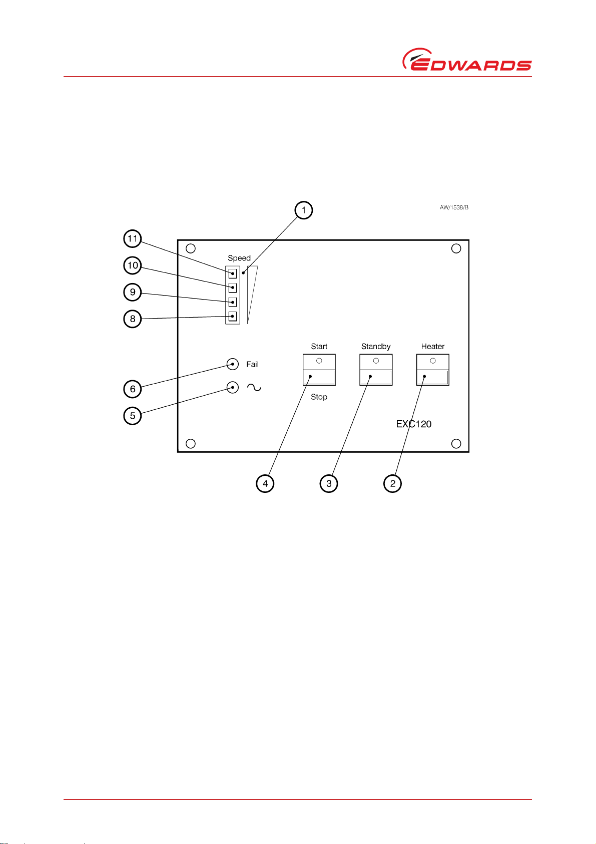
1.3 Controls and indicators (EXC120/300/ 300M only)
Note: In addition to the controls and indicators on the front panel, the EXC120, EXC300 and EXC300M Controllers
have an electrical supply isolator on the rear panel (s ee Fig ures 3 to 5).
The controls and indicators on the front panel of the EXC120, EXC300 and EXC300M Controllers are shown in Figures
1 and 2 and are described b el ow.
Start/Stop
Use this latching butt o n to a lter na te ly Sta r t or Stop the EXT pump. A LED on the button goes on whe n EXT Start has
been selected. Note that:
z The button is wired in series with the Start/Stop input on the logic interface (see Section 1.7.3). The EXT
pump will not start unt il Start i s sel ected from t his front panel butt on and the Start/Sto p input is c losed. T he
Controller is supplied with a wire link to close the Start/Stop input.
z If the LED on the button is on, it only means that Start has been selected; it does not necessarily mean that
the pump has successfully started.
z The Controller delays the Start operation until the Inte rlocks are closed (refer to Section 1.7.3) ; therefor e,
the EXT pump will not necessarily start to operate when you select Start. If you select Start and the
Interlocks are not closed, the LED on the button will flash.
Introduction
This button is also used to reset the Controller after Fail or Axial Emergency condition (see Section 4.9).
Standby
Use this latching button to select pu mp Standby mode a t any time. In Standb y, the rotational speed of the EXT pump
is reduced to 70% of its full rotational speed. Selection of Standby prolongs the li fe of the pump bearings. No te that:
z The button is wired in parallel with the Sta n dby input on the logic interface (see Section 1.7.3) and you can
use either the button or the input to select Standby.
z The LED on the button is on when Standby is selected (either by the button or by the Standby input).
Heater
Use this switch to s witch o n the electr ical su pply to the bakeout band. Note that the Controller only switches on the
electrical supply to the bakeout band when the EXT pump speed reaches the Normal speed setpoint (see
Section 1.7.4).
The LED on the switch is on when the electrical supply to the bakeout band is switched on; t his LED can therefore be
used as an indication that the pump has reached Normal speed.
© Edwards Limited 2008. All rights reserved. Page 3
Edwards and the Edwards logo are trademarks of Edwards Limited.
Page 12
D396-14-880 Issue J
1. Speed indicator
2. Heater (bakeout band ) switch
3. Standby button
4. Start/Stop button
5. Electrical supply LED
6. Fail LED
7. Not used
8. Pump rotating LED (amber)
9. Pump speed >25% LED (amber)
10.Pump speed >50% LED (green)
11.Pump speed >75% LED (green)
Introduction
Figure 1 - EXC120 Controller front panel
Page 4 © Edwards Limited 2008. All rights reserved.
Edwards and the Edwards logo are trademarks of Edwards Limited.
Page 13
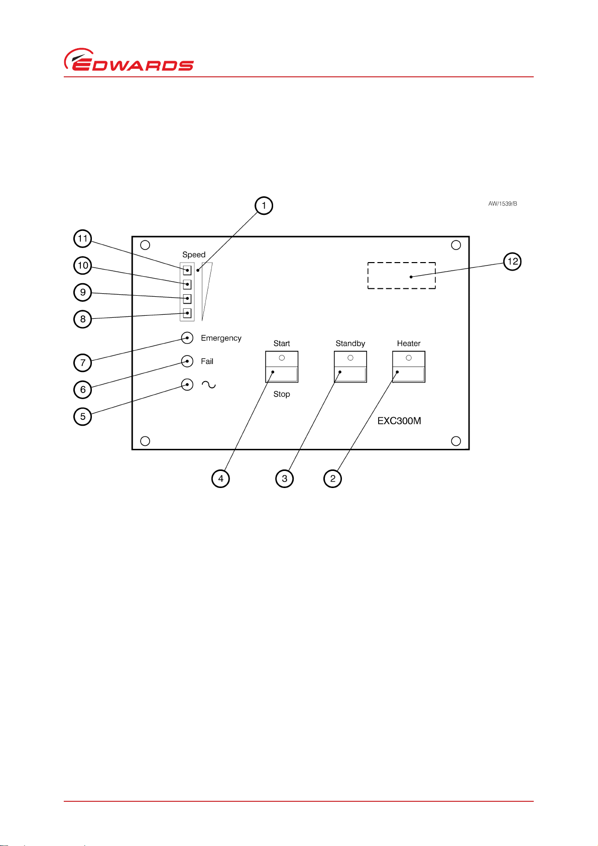
Figure 2 - EXC300/300M Controller front panel
1. Speed indicator
2. Heater (bakeout band) switch
3. Standby button
4. Start/Stop button
5. Electrical supply LED
6. Fail LED
7. Emergency LED (EXC300M only)
8. Pump rotating LED (amber)
9. Pump speed >25% LED (amber)
10.Pump speed >50% LED (green)
11.Pump speed >75% LED (green)
12.Hours counter (EXC300 only)
D396-14-880 Issue J
Introduction
© Edwards Limited 2008. All rights reserved. Page 5
Edwards and the Edwards logo are trademarks of Edwards Limited.
Page 14

D396-14-880 Issue J
Introduction
Speed
The speed indicator has 4 LEDs which go on to indicate the rotational speed of the EXT pump. Each LED goes on when
the speed of the pump is above a certa in value, represented as a percentage of the fu ll operating speed of the pump.
Refer to Figures 1 and 2: the bottom LED (8) goes on as soon as the pum p rotor starts to rotate; the ne xt LED (9) goes
on when the rotational speed is > 25% of full rotational s peed . The first green LED (10) goes on when the speed is >
50% of full rotational speed; the top LED (11) goes on when the speed is > 75% of full rotational speed. Note that:
z When the pump starts, the botto m LED goes on as soon a s the pump r ot o r sta rt s to rota te.
z When the pump decelerates, the bottom LED goe s off as soon as the pump speed falls to below 10% of full
rotational speed.
z When only the bottom two LEDs are on, the pump speed i s belo w 50% of its full ro ta ti onal spe ed and the
Controller may trip into Fail condition, depending on how you have configured the Controller (see
Section 1.9.2).
z When the pump is at Standby rotational speed, the top LED is off.
Emergency
This LED is only available on the EXC300M Controller. When the LED is on, this indicates an Axial Emergency condition
(refer to Section 1.9.3).
Fail
This LED is on when the Controller has tripped into Fail condition (refer to Section 1.9).
~
This LED is on when the Controller is connected to the electrical supply and the electrical supply isolator on the rear
of the Controller (see Figures 3 and 5) is switched on.
Hours counter
This counter is only available on the EXC300 Controlle r. The counter show s t h e tota l ela ps e d time that the EXC300
Controller has operated an EXT pump.
1.4 Bakeout band control (EXC120/300/300M only)
The EXC120, 300 and 300M Controllers can be used to operate a bakeout band.
The Controller will switch on the electrical supply to the bakeout band when the Heater switch on the front panel is
switched on and the EXT pump is at Normal speed (refer to Sections 1.3 and 1.7.4).
Page 6 © Edwards Limited 2008. All rights reserved.
Edwards and the Edwards logo are trademarks of Edwards Limited.
Page 15

D396-14-880 Issue J
1.5 Connection of an Active gauge
Note: If you connect a n Edwar ds Acti ve gauge to oper ate the TM PI con trol i nput si gnal to the logic inter face, y ou
cannot also use another sign al to operate the TMPI control i n pu t.
You can directly connect an Edwards Active gauge to the Controller (refer to Section 7.3.5 for suitable gauges). For
example:
z You can use the set-point facility of an APG Active Pirani Gauge or an AT C Active Thermocouple Gauge
(which is used to measure system or backing pressure) to operate the TMPI control input signal to the logic
interface.
z You can connect an AIM Active Inverted Magnetron Gauge and use the Controller TMP Normal signal to switch
the gauge on. This allows you to control the AIM Gauge without the need to use an additional high pressure
gauge (and its associated control equipment) to interlock the operation of the AIM Gaug e to system pressure.
Refer to Section 3.9 for details of the connection of an Active ga uge to the Cont rolle r.
If you want to use any alternative gauges, you must connect the gauge to its associated control equipment and then
connect the set-point output of the control equipment to the logic interface.
1.6 Backing pump control (EXC120/300/300M only)
Introduction
The EXC120, EXC300 and EXC300M Controllers can be used to control the operation of a backing pump through a
backing pump relay. The operation of this relay depends on how you have configured the Controller to operate the
vent-valve: refer to Sections 1.8 and 3.13.
1.7 Logic interface
1.7.1 Introduction
The rear panel of the Controller has a logic interface connector (see F igures 3 to 5) which you can use to connect the
Controller to your own equipment. The EXC120 and EXC120E Controllers have a 17-way connector and the EXC300
and EXC300M Controllers have an 18-way connector.
Signals on the logic interface are of four types:
z Electrical supplies These are electrical supplies for accessories connected to your pump; that is,
the vent-valve and the air-coo ler.
z Control inputs These are switch-type input signals which are used to control the operation of
the pumping system.
z Status outputs These outputs identify the status of the pump and the Controller.
z Analogue output The speed output provides an indication of the EXT pump speed.
Refer to Table 3 and to Figures 8 and 9 for detailed information about the logic interface pins and their uses. A
general description of the logic interface connections follows.
© Edwards Limited 2008. All rights reserved. Page 7
Edwards and the Edwards logo are trademarks of Edwards Limited.
Page 16

D396-14-880 Issue J
Introduction
1.7.2 Electrical supplies
Two 24 V supplies are provided, as described below
Vent-valve supply
This electrical supply is provided to operate a vent-valve fitted to your EXT pump or va cuum system. The Controller
automatically opens the valve when the speed of the pump falls to below 50% of full rotational speed (see
Section 1.8). You can also configure the Controller to operate the valve in other specific conditions: refer to Sections
1.8 and 3.13.
Air-cooler supply
This electrical suppl y is prov ided to operate an ACX air-cooler fitted to your EXT pump. The electrical supply is on
whenever the Controller is on. If your pump is water-cooled, you can use this supply to operate a solenoid-valve to
control the flow of water through the water-cooler.
1.7.3 Control inputs
Note: The Controller is supplied with wire links fitted to close the TMP and SYS Interlocks and to close the Start/
Stop input. Th e C ontroller cann o t start the EXT pump if an y of these three inputs are open.
You can use these signals to control the operation of the EXT pump. The signa ls are switch-type inputs in w hich two
pins on the logic interface are linked (closed) when you want to set the required s ignal and are unconnecte d (open )
when you do not wish to set the signal.
Two of the inp uts (Start/Stop and Standby ) have the same functions as the buttons of the sam e name on the
Controller front panel (on EXC120, EXC300 and EXC300M Controllers). The other two inputs are Interlocks and the
Controller will only operate the EXT pump if both Interlocks are closed (and if no Fail condition is present).
Start/Stop
Use the Start/Stop input to Start and Stop the EXT pump. Note that on the EXC120, EXC300 and EXC300M Controllers,
the signal is wired in s eries with th e Start/Stop b utton on the fr ont panel, so yo u must close the St art/Stop i nput and
press the Start/Stop button o n the fr o nt panel to Start the pump. To stop the pump, either open the input (that i s ,
open the link between the appropriate logic interface pins), or press the Start/Stop button again.
Standby
Close the Standby input to select pump Standb y (refer to Section 1.3). Note that on the EXC120, EXC300 and EXC300M
Controllers, the Standby input is wired in parallel with the Stan dby button on the front pa nel and you can use either
the button or the input to select Standby at any time.
TMP Interlock (TMPI)
Use the TMP Interlock to de lay the start of the EXT p ump until the backing pump has suff iciently reduced the pressure
in the vacuum system . You can therefore control the TMP Interlock either by a timer or by a pressure switch in the
backing pipeline of yo ur system. Note that:
z If the TMP Interlock is open when Start i s selected, the Start LED on the Start/Stop butto n will fl as h.
z If the TMP Interlock is opened after Start is selected, but with the SYS Interlock open, the Sta rt LED will
continue to flash.
z If the TMP Interlock is opened after the EXT pump has started, the Controller will trip into Fail condition.
Page 8 © Edwards Limited 2008. All rights reserved.
Edwards and the Edwards logo are trademarks of Edwards Limited.
Page 17

D396-14-880 Issue J
SYS Interlock (SYSI)
Note: The EXC120E Controller does not have a backing pump relay.
Use the SYS Interlock to interlock the Con troller to a sys tem fail or control signal, for example, a position switch on
a door of the vacuum chamber or a start contactor for a backing pump.
When the SYS Interlock opens:
z the backing pump relay opens (see Section 1.8)
z the electrical supply to the vent-valve is switched off (see Section 1.8).
Note that:
z If the SYS Interlock is open when Start is selected, the Start LED on the Start/Stop button will flash.
z If the SYS Interlock is opened after Start has been selected, but wi th the TM P Interl oc k op en, the Start LE D
will continue to flash.
z If the SYS Inter l o ck is opened afte r the EXT pump has star ted, the Contr o ller will trip into Fail conditio n . If
the SYS Interlock then closes again, the vent option you have selected (refer to Sections 1.8 and 3.13) will
determine the operation of the backing pump relay and the electrical supply to the vent-valve.
1.7.4 Status outputs
Introduction
The Controller provides Normal and Fail status output signals (TMP Normal and TMP Fail) through volt-free contacts
on the logic interface connector. The EXC300M Controller also provides a n Ax ial Em erg ency cond itio n sig nal ( als o on
a volt-free contact). These signals can be used to control devices in the pumping system or provide remote status
output signals.
The signals operate as described below.
z TMP Normal TMP Normal is normally open and closes when the EXT pump speed reaches the
Normal speed setpoint. The Normal speed setpoint is determined by a
potentiometer on the top of the Controller. The Controller is supplied with the
potentiometer adjusted s o that the No rm al speed setpoint is 80% of full rotationa l
speed. You can adjust the Norm al sp e ed setpoint as described in Section 3.11.
z TMP Fail TMP Fail is normally closed and opens when the Controller trips into Fail condition
(see Section 1.9).
z Axial Emergency
(EXC300M only)
Axial Emergency is normally closed and opens when an Axial Emergency is detected
(see Section 1.9.3).
1.7.5 Analogue outputs
The Pump Speed analogue output signal is proportional to EXT pump speed. Connect the ou tput to a suitab l e m eter
or indicator to display the pump speed or connect the output to your control equipment (for example, to operate
other components in the pumping system at preset EXT pump speeds).
© Edwards Limited 2008. All rights reserved. Page 9
Edwards and the Edwards logo are trademarks of Edwards Limited.
Page 18

D396-14-880 Issue J
Introduction
1.8 Vent-valve control
Notes: 1. The EXC120E Contr oller do es not h av e a backing pump relay.
2. The vent option factory settings are shown in Table 7.
Provided that the SYS Interlock is closed: if the Controller electrical supply fails, the Controller maintains the
electrical supply to the vent-valve until the pump speed falls to below 50% of full rotational speed. The Controller
then switches off the vent-valve electrical supply and ope ns the backing pump relay. This fea ture of the Controller
cannot be reconfigured.
However, you can use the configuration DIP switches on the Controller (refer to Section 3.13) to select any one of
(or any combination of) the following options:
z Vent on Stop (Stop selected either by the front-panel butto n or the Star t/ Sto p inp ut on the lo gi c interf ac e) .
z Vent on Fail condition.
z Ve nt on Axial Emergency condition (only available on the EXC300M Controller: see Section 1.9.3).
When a selected vent option condition is detected, the Controller:
z waits approximately 2 seconds, to allow a vacuum system isolation-valve (i f f itted) to close,
z then switches off the electrical supply to the vent-valve,
z then opens the backing pump relay.
1.8.1 Vent on Stop
Note: If the SYS Interlock opens, a Fail condition will occur and the Controller will switch off the vent-valve
electrical supply: see Sections 1.9.1 and 3.13.
Vent on Stop se lected
When you switch on the Controller, the vent-valve electrical supply remain s off until St art is selected . Provided that
the SYS Interlock is closed, the Controller switches the vent-valve electrical supply on when Start is selected.
If Stop is then selected, the Controller switches the vent-valve electrical supply off again.
Vent on Stop not se l ected
When you switch on the Controller, the vent-valve electrical supply remain s off until St art is selected . Provided that
the SYS Interlock is closed, the Controller switches the vent-valve electrical supply on when Start is selected.
If Stop is then selected, the EXT pump will decelerate. The vent-valve electrical supply will remain on until t he pump
speed falls to be low 50% o f full ro tational s peed, at which point the vent- valve electrical supply will be switched off.
1.8.2 Vent on Fail and Vent on Axial Emergency
Note: The Vent on Axial Emergency option is only available on the EXC300M Controller.
If the Controller is configured to Vent on Fail or Vent on Axial Emergency, the Controller will switch off the ventvalve electrical supply as soon as Fail cond ition or Axial Emergency condition is dete ct e d.
Page 10 © Edwards Limited 2008. All rights reserved.
Edwards and the Edwards logo are trademarks of Edwards Limited.
Page 19

D396-14-880 Issue J
1.9 Controller Fail conditions
1.9.1 General
The Controller will trip into Fail condition if any of the following occurs:
z The TMP or SYS Interlock opens while the EXT pump is operating (see Note 1 below).
z The EXT pump does not reach 50% of full rota tional sp eed within a preset time after it starts (t he time set by
the adjustable Internal Timer: see Sections 1.9.2 and 3.12).
z The EXT pump speed falls to below 50% of its full rotational speed (see Note 2 below).
z The EXT pump speed is too high (above 1.07% of full rotational speed).
z The pump-to-controller cable is disconnected while the EXT pump is operating.
When the Controller trips into Fail condition:
z the electrical supply to the EXT pump-motor is switched off
z the TMP Fail status output signal on the logic interface opens and (on the EXC120, EXC300 and EXC300M
Controllers) the Fail LED on the front panel goes on.
Introduction
z The operation of the vent-valve and backi ng pump relay depends on how you have configured the Controller
(refer to Sections 1.8 and 3.13). To reset the Controller after Fail condition, refer to Section 4.9.
Notes: 1. If the Controller trips into Fail condition because the SY S In te r l o ck ha s opened, the Cont ro l l e r will
switch off the vent-valve electrical supply and (for the EXC120, EXC300 and EXC300M Controllers only)
will open the backing pump relay. The operation of the vent-valve in other Fail conditions depends on
how you have configured the Controller: refer to Sections 1.8 and 3.13.
2. If you enable the Internal Ti mer (see Sections 1.9.2 and 3.13.2), the Controller will trip into Fail
condition only after the preset time has elapsed.
1.9.2 Internal Timer
Note: The Internal Timer starts when the Controller starts the EXT pump, not when Start is selected (either by
the front-pan el butt on or th e logi c inter face Start/ Stop inp ut). For exam ple, if the Sta rt butt on is pr essed
to start the pump whe n the TMP Interloc k i s op en, the Internal Tim er wi ll onl y s ta rt when the Interlock
closes and the Controller starts the pump.
The Internal Timer has two functions:
Firstly, when the EXT pump is started by the Co ntro l ler , the Inter na l Time r in the Cont roll er als o sta rts . If th e EXT
pump does not reach 50% of full rotational speed within the preset time measured by the timer, the Controller will
trip into Fail condition. Th is f u n c tion cannot be disabled.
Secondly, you can configure the Controller to enable or disable the Internal Timer if the pump speed falls during
pump operation:
z If you disable the Internal Timer, the Controller will trip into Fail condition as soon as the pump speed falls
to below 50% of full rotational speed.
z If you enable the Internal Timer , t he Inte rnal Timer will start as soon as the pump speed falls to below 50% of
full rotational speed; the Controller will trip into Fail condition if the pump speed is still below 50% of full
rotational speed at the end of the preset time.
The Controller is supplied with the Internal Timer enabled and adjusted for a preset time of 8 minutes. You can adjust
the timer for your application: refer to Section 3.12.
© Edwards Limited 2008. All rights reserved. Page 11
Edwards and the Edwards logo are trademarks of Edwards Limited.
Page 20

D396-14-880 Issue J
Introduction
1.9.3 Axial Emergency (EXC300M only)
The EXT250M pump has sensors which detect the axial displacement of the pump rotor; the outputs of these sensors
are monitored by the Controller.
The Controller trips into Axial Emergency condition if:
z The displacement of the rotor exceeds set limits for more than 2 seconds.
z The displacement of the rotor repeatedly exceeds set limits (due to oscillation).
When the Controller trips into Axial Emergency condition, the electrical supply to the pump-moto r is switched off,
the Emergency LED on the front panel goes on and the Axial Emergency status output signal on the logic interface
opens. The EXT250M pump electromagnetic bearings remain active, although the rotor assembly may contact the
safety bearings if the axial loading exceeds the capabilities of the bearing drive.
1.10 Electrical connections
All electrical connections to the Controller are on the rear panel: see Figures 3 to 5.
Page 12 © Edwards Limited 2008. All rights reserved.
Edwards and the Edwards logo are trademarks of Edwards Limited.
Page 21

Figure 3 - Rear panel of the EXC120 Controller
1. Electrical supply isolator
2. Earth (ground) stud
3. Bakeout band connector
4. EXT pump connector
5. Logic interface connector
6. Active gauge connector
7. Backing pump connector
8. Bakeout band fuse
9. Electrical supply fuse
10.Electrical supply connector
D396-14-880 Issue J
Introduction
© Edwards Limited 2008. All rights reserved. Page 13
Edwards and the Edwards logo are trademarks of Edwards Limited.
Page 22

D396-14-880 Issue J
1. Electrical supply connector
2. EXT pump connector
3. Logic interface connector
4. Active gauge connector
5. Earth (ground) stud
6. Electrical su pply fuse
Introduction
Figure 4 - Rear panel of the EXC120E Controller
Page 14 © Edwards Limited 2008. All rights reserved.
Edwards and the Edwards logo are trademarks of Edwards Limited.
Page 23

Figure 5 - Rear panel of the EXC300/300M Controller
1. Electrical supply isolator
2. Bakeout band connector
3. Earth (ground) stud
4. EXT pump connector
5. Active gauge connector
6. Logic interface connector
7. Cooling-fan
8. Bakeout band fuse
9. Backing pump connector
10.Electrical supply connector
11.Electrical supply fuse
D396-14-880 Issue J
Introduction
© Edwards Limited 2008. All rights reserved. Page 15
Edwards and the Edwards logo are trademarks of Edwards Limited.
Page 24

D396-14-880 Issue J
This page has been intentionally left blank.
Page 16 © Edwards Limited 2008. All rights reserved.
Edwards and the Edwards logo are trademarks of Edwards Limited.
Page 25

D396-14-880 Issue J
2Technical data
2.1 Operating and storage conditions
Table 1 - Operating and storage conditions
Ambient operating temperature range 0 to 35 °C
Ambient storage temperature rang e -20 to 40 °C
Maximum ambient operating humidity 10 to 95% RH (non-condensing to DIN 40040)
Maximum operating altitude 3000 m
2.2 Mechanical data
Table 2 - Mechanical data
Dimensions See Figures 6 and 7
Mass See Table 5
Connectors See Table 6
Technical data
2.3 Electrical data
Table 3 - Logic interface electrical data
Relay contact rating (resistive load) 1 A at 25 V d.c.
Remote contr ol signals
Control voltage: low (close) < 0.8 V d.c.
Control voltage: high (open) 4 to 24 V d.c.
Maximum input current (at 24 V) 80 μA
Maximum output current (at 0 V d.c.) 160 μA
Air-cooler electrical supply See Table 6
Vent- valve electri cal supply See Table 6
Analogue EXT pump speed output
Output voltage 0 to +5 V d.c., proportional to EXT speed
Maximum output current 5 mA
Table 4 - Fuse ratings
Electrical supply fuse
EXC120/EXC120E 3.15 A, type T 20 mm
EXC300/EXC300M 6.3 A, type T 20 mm
Bakeout band fuse
90 to 132 V a.c. electrical supply 1 A, type F 20 mm
180 to 264 V a.c. electrical supply 0.5 A, type F 20 mm
*
Not applicable to the EXC120E Controller.
*
© Edwards Limited 2008. All rights reserved. Page 17
Edwards and the Edwards logo are trademarks of Edwards Limited.
Page 26

D396-14-880 Issue J
Technical data
Table 5 - Controllers electrical and other technical data
Parameter EXC120 EXC120E EXC300 EXC300M
Mass 2 kg 1.3 kg 4.6 kg 4.6 kg
Cooling Natural
convection
Electrical supply voltage 90 to 264 V a.c. 90 to 264 V a.c. 90 to 132 or
Electrical supply frequency 47 to 63 Hz 47 to 63 Hz 47 to 63 Hz 47 to 63 Hz
Maximum input power 400 V A 260 VA 700 VA 700 VA
Peak inrush current 27 A at 110 V a.c.
54 A at 240 V a.c.
Compatible EXT pumps EXT70, EXT250
EXT351, EXT501
EXT pump-motor electrical supply
Maximum continuous
output power 110 W 110 W 290 W 290 W
Maximum output voltage 90 V peak to peak 90 V peak to peak 90 V peak to peak 90 V peak to peak
Switching frequency 32 kHz 32 kHz 32 kHz 32 kHz
Nominal commutation
frequency 600 Hz to 1.5 kHz 600 Hz to 1.5 kHz 600 Hz to 1.5 kHz 600 Hz to 1.5 kHz
Maximum commutation
frequency 1.07 x nominal 1.07 x nominal 1.07 x nominal 1.07 x nominal
Standby frequency 70% of nominal 70% of nominal 70% of nominal 70% of nominal
Maximum continuous axial
bearing current ---4.75 A
Axial bearing drive voltage
Maximum - - - 26 V d.c.
Minimum - - - 10 V d.c.
Air-cooler electrical supply
Voltage range +18 to +26 V d.c. +18 to +26 V d.c. +12 to +26 V d.c. +12 to +26 V d.c.
Maximum output current 100 mA 100 mA 100 mA 100 mA
Vent- valve electri cal supply
Voltage range +18 to +26 V d.c. +18 to +26 V d.c. +12 to +26 V d.c. +12 to +26 V d.c.
Maximum output current 80 mA 80 mA 80 mA 80 mA
Bakeout band electrical supply
Voltage range 90 to 132 or
180 to 264 V a.c
Maximum power 150 W - 150 W 150 W
Natural
convection
27 A at 110 V a.c.
54 A at 240 V a.c.
EXT70, EXT250
EXT351, EXT501
- 90 to 132 or
Forced air Forced air
180 to 264 V a.c.
27 A at 110 V a.c.
54 A at 240 V a.c.
EXT70, EXT250
EXT351, EXT501
180 to 264 V a.c
90 to 132 or
180 to 264 V a.c.
27 A at 110 V a.c.
54 A at 240 V a.c.
EXT250M
90 to 132 or
180 to 264 V a.c
Page 18 © Edwards Limited 2008. All rights reserved.
Edwards and the Edwards logo are trademarks of Edwards Limited.
Page 27

2.4 Electrical connectors
Table 6 - Electrical connectors data
Electrical supply connector socket type CEE/IEC 320
Earth (ground) stud (on rear panel) M4
Backing pump relay connector
Socket type Stak 200
Maximum voltage 250 V a.c.
Maximum current (a.c. r.m.s. inductive load,
0.8 pf lagging) 15 A
Bakeout band connector
Socket type CEE/IEC 320
Maximum power 150 W
Active gauge connector
Signals on the connector pins See Figure 16 and Table 11
Socket type FCC68, 8-way
Manufactu r er Western Electric
Maximum power 3 W
Logic interface connector
Socket type (EXC120/120E/300M) MVSTBR 2,5/17-st5,08
Socket type (EXC300) MVSTBR 2,5/18-st5,08
Manufacturer Phoenix Combicon
*
Not applicable to the EXC120E Controller.
*
*
D396-14-880 Issue J
Technical data
2.5 Factory settings
Table 7 - Factory settings
Normal speed setpoint 80% of full rotational speed
Internal Timer 8 min, enabled
V e n t options See Table 10
Logic interface: pins linked on the mating connector
EXC120/E Pins 8 & 9, pins 12 & 13, pins 14 & 15
EXC300/M Pins 9 & 10, pins 13 & 14, pins 15 & 16
© Edwards Limited 2008. All rights reserved. Page 19
Edwards and the Edwards logo are trademarks of Edwards Limited.
Page 28

D396-14-880 Issue J
1. Front pan e l
2. View from top
3. Clearance for cables
4. Clearance for ventilation
5. Pa n e l c ut-out
A. EXC120
B. EXC300/EXC300M
Technical data
Figure 6 - EXC120, EXC300 and EXC300M Controller dimensions (mm)
Page 20 © Edwards Limited 2008. All rights reserved.
Edwards and the Edwards logo are trademarks of Edwards Limited.
Page 29

Figure 7 - EXC120E Controller dimensions (mm)
1. Front panel
2. Clearance for ventilation
3. View from top
4. Clearance for cables
5. Panel cut-out
D396-14-880 Issue J
Technical data
© Edwards Limited 2008. All rights reserved. Page 21
Edwards and the Edwards logo are trademarks of Edwards Limited.
Page 30

D396-14-880 Issue J
This page has been intentionally left blank.
Page 22 © Edwards Limited 2008. All rights reserved.
Edwards and the Edwards logo are trademarks of Edwards Limited.
Page 31

D396-14-880 Issue J
CAUTION
WARNING
3 Installation
3.1 Unpack and Inspect
Remove all packing materials and inspect the Controller. If the Controller is damaged, n otif y your supplier an d the
carrier in writing within three days; state the Item Number of the Controller together with your order number and
your suppliers invoice number. Retain all packing materials for inspection. Do not use the Controller if it is damaged.
Check that your package contains the items listed in Table 8. If any of these items is missing, notify your supplier in
writing within t hree days.
If the Controller is not to be u sed immedi ately, sto re the Controller in suitable conditions as described in Section 6.1.
Table 8 - Checklist of items
Quantity Description Check (✓)
1EXC Controller
1 Backing pump relay electrical connector
1 Security bracket for backing pump relay connector
1 Logic interface electrical connector ❏
1 Electrical supply cable ❏
1 In-line filter
1 Double-sided earth (ground) tab
*
Not supplied with the EXC120E Controller.
†
Only supplied with the EXC300 and EXC300M Controllers.
‡
Only supplied with the EXC300M Controller; only needed if dual earth (g r ound)
bonding is required.
†
‡
*
*
❏
❏
❏
❏
❏
Installation
3.2 Fit the Controller
The Controller contains electrolytic capacitors and, under certain fault conditions, may emit
dangerous fumes. Ensure that the Controller is operated in a well-ventilated area.
You must allow the correct clearances for air circulation and you must fit the EXC120E Controll er onto a
thermally conductive surface. If you do not, the performance of the Controller may be affected at high operating
temperatures.
The Controller can be used on a bench-top or can be fitted in a rack or cabinet. You can operate the EXC120, EXC300
and EXC300M Controllers in a hori zontal position or in a vertica l posi ti on wi th the fr o nt pa nel at the top. You can
operate the E XC 1 20E Control l er in a horizontal position or in a vert ic al position with the side vents at th e top.
When you fit a Controller in a rack or a cabinet, you must allow 15 mm clearance at the sides of the Controller for
air circulation and you must allow 75 mm clearance at the back of the Controller for the cables. Do not obstruct the
cooling-fan on the EXC300 and EXC300M Controllers. The size of the front panel cut-out required and the lo cation of
the front panel fixing holes for the EXC120, EXC300 and EXC300M Controllers are show n in Figure 6.
When you fit the EXC120E Controller, you must firmly fit the Controller onto a thermally conductive material, for
example aluminium or steel. The location of the bottom panel fixing-holes are shown in Figure 7.
© Edwards Limited 2008. All rights reserved. Page 23
Edwards and the Edwards logo are trademarks of Edwards Limited.
Page 32

D396-14-880 Issue J
Installation
3.3 Introduction to Controller electrical connections
When you make the electrical connections to the Controller described in the following sections, refer to Table 9 for
full details of the logic interface connections and refer to Figures 8 and 9 which show schematic diagrams of the
electrical connections. Take note of the following:
z The backing pump and bakeout band connectors are not available on the EXC120E Controller.
z The EXC120 and EXC120E Controllers have a 17-way logic interface connec tor. The EXC300 and EXC300M
Controllers have an 18-way logic interface connector.
You must provide suitable strain-relief on the cables which you fit to the Controller.
Table 9 - Logic interface pins
Pin number
(EXC300/M)
Signal Polarity
Signal
*
type
1 Vent-valve electrical supply: 24 V +
2 Vent-valve electrical supply: 0 V
†
-2
Supply
3 Air-cooler electrical supply: 24 V +
Supply
4 Air-cooler electrical supply: 0 V - 4
5 TMP Normal (closed when pump speed
N/A
reaches the Normal speed setpoint)
6 TMP Fail (open when fail condition e xists) N/A 6
7 Axial Emergency (open when Axial
Emergency condition exists)
‡
N/A -
Status
outputs
8 Status out put isolated co m m on N/A 7
**
9
Start/Stop: Close for Start
**
10
11
Standby: Close for Standby
12 - 11
**
13
14
15
16
TMPI (TMP Interlock): Close
for EXT pump operation
**
**
SYSI (SYS Interlock): Close
for backing pum p operation
**
+
- 9
+
Control
input
Control
input
+
- 13
+
- 15
Control
input
Control
input
Pin number
(EXC120/E)
1
3
5
††
8
††
10
††
12
††
††
14
††
17
Pump speed
18 - 17
*
+ = positive, - = negative, N/A = not applicable.
†
This supply line is raised to +24 V to de-energise the valve coil and vent the system.
‡
Only available on the EXC300M Controller.
**
The EXC300/300M Controller is supplied with pins 9 and 10 linked together, pins 13 and 14
linked together and pins 15 and 16 linked together on the mating connector .
††
The EXC120/E Controller is supplied with pins 8 and 9 linked together, pins 12 and 13 linked
+
Analogue
16
output
together and pins 14 and 15 l i nked together on the mating co n ne ctor.
Page 24 © Edwards Limited 2008. All rights reserved.
Edwards and the Edwards logo are trademarks of Edwards Limited.
Page 33

D396-14-880 Issue J
1. External elect rical sup p ly
2. Earth (ground)
3. Electrical supply connector
4. Electrical supply isolator
5. Front panel Heater switch *
6. Bakeout band fuse *
7. Rear panel bakeout band conn ecto r *
8. Bakeou t b a nd *
9. Backing pu mp
10.Backing pump relay *
11.Rear panel backing pump relay connector *
12.Rear panel Active gauge connector
13.Active gauge
14.Speed indicator
15.Logic interfac e co n n e ctor
16.External SYS Interlock switch
17.External TMP Interlock switch
18.External Remote Standby switch
19.External Remote Start/Stop switch
20.TMP Normal output (normally open)
21.TMP Fail output (normally closed)
22.Not used
23.Vent-valve
24.Air-cooler
25.Remote indicator equipment
A. Vacuum and control system
B. EXC Controller
L. Live electrical supply
N. Neutral electrical supply
E. Earth (ground) electrical supply
* Not available on the EXC120E Controller.
Figure 8 - Schematic diagram of EXC120 & EXC120E Controller electrical connections
Installation
© Edwards Limited 2008. All rights reserved. Page 25
Edwards and the Edwards logo are trademarks of Edwards Limited.
Page 34

D396-14-880 Issue J
1. External elect rical sup p ly
2. Earth (ground)
3. Electrical supply connector
4. Electrical supply isolator
5. Front panel Heater switch
6. Bakeou t b a nd fuse
7. Rear panel bakeout ba nd connecto r
8. Bakeou t b a nd
9. Backing pu mp
10.Backing pump relay
11.Rear panel backing pump relay connector
12.Rear panel Active gauge connector
13.Active gauge
14.Speed indicator
15.Logic interfac e co n n e ctor
16.External SYS Interlock switch
17.External TMP Interlock switch
18.External Remote Standby switch
19.External Remote Start/Stop switch
20.TMP Normal output (normally open)
21.TMP Fail output (normally closed)
22.Axial Emergency output (normally closed) *
23.Vent-valve
24.Air-cooler
25.Remote indicator equipment
* EXC300M Controller only.
A. Vacuum and control system
B. EXC Controller
L. Live electrical supply
N. Neutral electrical supply
E. Earth (ground) electrical supply
Installation
Figure 9 - Schematic diagram of EXC300 & EXC300M Controller electrical connections
Page 26 © Edwards Limited 2008. All rights reserved.
Edwards and the Edwards logo are trademarks of Edwards Limited.
Page 35

D396-14-880 Issue J
WARNING
3.4 Connect the electrical supply
High voltages exist in the Controller when it is operating. Ensure that the Controller is earthed
(grounded) and observe all appropriate safety precautions for the safe installation and handling of
electrical equipment. If you do not, there will be a danger of injury or death to people by electric
shock.
Note: If you will use an EXC300 or EXC300M Controller in a commercial or residential environment, you must fit
the in-line fil t er supplied to the e l ec tr i cal supply conn ec to r on the Controller, then fit the con n e ctor on
the electrical supply cable to the filter.
1. Connect the wires at one end of the electrical supply cable to a suitably rated and fused electrical supply; if
required, connect the wires to a suitably rated plug. Connect the wires as follows:
z Connect the green/yellow wire to earth (ground).
z Connect the brown wire to the live electrical supply.
z Connect the blue wire to the neutral electr ica l supp ly.
2. On EXC120, EXC300 and EXC300M Controllers, ensure the electrical supply isolator on the rear panel is in the off
position.
Installation
3. Fit the connector on the other end of the electrical supply cable to the electrical supply connector on the rear
of the Controller (see Figures 3 to 5).
3.5 Connect additional earth (ground) bonding (if required)
Protective earthing (grounding) for electrical safety of the EXC Controller, EXT pump and accessories is provided by
the electrical supply cables and connectors and the pump-to-controller cable. However, additional earth (ground)
bonding may be required to improve the reliability of the system by reducing any effects of RFI (radio frequency
interference), particularly if the vacuum system is prone to high voltage discharges or other radio frequency
emissions.
Use good EMC (electromagnetic compatibility) practices and take note of the following EMC earthing (grounding)
guidelines to reduce the susceptibility of the system to RFI:
z Connect the Controller, the EXT pump and the vacuum chamber to a common earth (ground) point on the
pumping system ; this star earth (gr o u nd) is typically in the electrical power distribution box.
z Clamp the Controller earthing (grounding) terminal between the two lock-nuts provided on the earth
(ground) stud on the rear panel of the Controller.
z Use suitable heavy duty ca ble or b raid t o ensure a low impeda nce bond to the e arth (g round) point ( typica lly
less than 0.1 Ω for each leg of the star).
z Use screened cable for all wiring to the logic interface connector. (The T AV5 vent-valve and the ACX Air
Cooler accessories are provided with screened cable.) Connect each screen to the Controller earth (ground)
stud to ensure that they are properly earthed (grounded).
3.6 Connect the EXT pump
Use a pump-to-controller cable (not supplied) to connect the Controller to the EXT pump. Fit the connectors on the
ends of the cable to the appropriate mating-halves on the Controller and on the EXT pump. The connectors are
polarised so you cannot fit a connector in the wrong orientation and different connector types are used on the
Controller and on the EXT pump, so you cannot fit the cables the wrong way round.
© Edwards Limited 2008. All rights reserved. Page 27
Edwards and the Edwards logo are trademarks of Edwards Limited.
Page 36

D396-14-880 Issue J
WARNING
Installation
3.7 Connect the backing pump (EXC120/300/300M only)
Fit an earth (ground) wire to the backing pump relay electrical connector. If you do not, the case
of the Controller may become live if there is a wiring fault.
Note: To control a backing pump w i th the EXC120E, use the 24 V d.c. vent-valve electrical supply on the logic
interfac e to operate the pump through a suita b l e relay or contactor. This configuration will provide
identical control logic to that for the backing pump relay on the other Controllers.
The single-pole backing pump relay in the Controller provides a switching signal to control the backing pump
electrical supply; it does not provide a backing pump electrical supply. You can use the ba cking pump relay to control
the backing pump in one of two ways:
z Directly, as shown in Figure 10.
z Through a contactor, as shown in Figure 11.
Use a suitably rated three-core cable to connect the backing pump to the Controller. If you use an external conta ctor,
ensure that the contactor is suitably rated for use in this way.
1. Connect the wires of your backing pump cable to the appropriate pins of the backing pump relay electrical
connector (supplied). The pins of the connector are used as follows:
Pin Use
1Live in
2Switched live out
3 Earth (ground)
2. Connect the other end of your cable to the backing pump and/or the ele ctrical supply, as appropriate.
3.8 Connect the bakeout band (EXC120/300/300M only)
If you have fitted a bakeout band to the EXT pump, insert a suitably rated fuse into the bakeout band fuse holder,
then fit the connector on the bakeou t band cabl e to the heater connector on the rear of the Controller (see Figures
3 and 5).
3.9 Connect an Active gauge
Use an Edwards Active gauge cable (available as an accessory: see Section 7.3.5) to connect an Edwards Active gauge
to the Controller through the active gauge connector on the rear of the Controller (see Figures 3 to 5).
If you want to use the set-p oint fac ility on a n Activ e Pirani Gauge or Active Thermocouple Gauge to operate the TMP
Interlock, you must remove the link fitted to the TMP Interlock control input on the logic interface; that is:
z On EXC120 and EXC120E Controllers, remove the link between pins 12 and 13.
z On EXC300 and EXC300M Controllers, remove the link between pins 13 and 14.
If you want to use the Controller TMP Normal relay to enable an Active Inverted Magnetron Gauge, you must connect
the TMP Normal relay isolated common line to the electrical supply 0 V line; that is:
z On EXC120 and EXC120E Controllers, link pins 4 and 7.
z On EXC300 and EXC300M Controllers, link pins 4 and 8.
Page 28 © Edwards Limited 2008. All rights reserved.
Edwards and the Edwards logo are trademarks of Edwards Limited.
Page 37

Figure 10 - Direct operation of the backing pump
1. EXC backing pump relay
2. Backing pump motor
3. EXC Controller
1. EXC backing pump relay
2. Backing pump motor
3. EXC Controller
D396-14-880 Issue J
Installation
Figure 11 - Operation of the backing pump through a contactor
© Edwards Limited 2008. All rights reserved. Page 29
Edwards and the Edwards logo are trademarks of Edwards Limited.
Page 38

D396-14-880 Issue J
CAUTION
CAUTION
Installation
3.10 Connect the logic interface to your equipment
Do not earth (ground) the logic interface 0 V line (pins 2 and 4). If you do, you will provide an earth (ground)
return path for any electrical fault in the pump-motor and this could damage the Controller or your control
equipment.
Do not connect voltages greater than 45 V to th e logi c interface. If you do, the Controller will not comply with
the low voltage safety recommendations of IEC 1010.
Note: If your backing pump will take more than 30 min utes to reduce the pr es s u r e in the va cuum chamber to
1 mbar, we recommend that you use the TMP Interlock to delay the EXT pump Start until this pressure is
reached.
The Controller is supplied with a mating-plug for the logic interface connector. A s suppli ed, this mati ng- plug has
three links fitted to close the TMP Interlock and SYS Interlock and to close the Start/Stop input. If you want to use
the Controller for stand-alone operation, you must fit this mating-plug to the logic interface connector on the rear
of the Controller (see Figures 3 to 5).
Use the appropriate pins on the mating-plug to connect your control equipment and accessories to the Controller, as
described in the previous sections and as shown in Table 9 and Figu re s 8 and 9. Note that, depending on how you
want to use the Controller, you may have to remove the factory fitted links from the mating-plug.
3.11 Adjust the Normal speed setpoint
Note: If you set the Normal speed setpoint to be more than 70% of full rotational speed, the TMP Normal relay
will open when you select Standby. The Controller is supplied with the Normal speed setpoint adjusted to
80% of full rotational speed.
You can adjust the Normal speed setpoint (at which the TMP Normal relay will close: see Section 1.7.4) between 65
and 95% of full rotational speed.
To adjust the Normal speed se tp oint, use a small screwdriver to turn the SET POINT potentiometer; an access hole
is provided on the top cover of the Control le r. Figure 12 detail A shows the approximate Normal speed setpoint
settings for different potentiometer adjustmen ts .
3.12 Adjust the Internal Timer
The Internal Timer can be adjusted between approximately 1 and 30 minutes. The Controller is supplied with the
Internal Timer adjusted to 8 minutes (see Section 1.9.2).
To adjust the Internal Timer, use a small screwdriver to turn the TIMER potentiometer; an access hole is provided on
the top cover of the Controller (see Figure 12).
1. Turn the potentiometer fully anticlockwise; thi s pos it ion corr es po nds to the minim u m ti me of ap pr o ximately 1
minute.
2. Turn the potentiometer clockwise to set the requi red time ; one full tur n adds a pproxi matel y two minu tes to the
set time. For example, seven full turns give a set delay time of approximately 15 minutes.
Page 30 © Edwards Limited 2008. All rights reserved.
Edwards and the Edwards logo are trademarks of Edwards Limited.
Page 39

Figure 12 - Top cover of the Controller
D396-14-880 Issue J
Installation
3.13 Configure the Controller
3.13.1 Introduction
The Controller has four DIP switches which can be used to configure the Controller for your application. The DIP
switches are on the top of the Controller (the CONFIG switches shown in Figure 12). Set the DIP switches as described
in the followin g sec tions.
3.13.2 Enable/d i sa b le th e Internal Timer to monitor low pump spe ed
Notes: 1. If you pump a high gas l oa d with the Intern al Timer enabled ( DIP switch 1 set to the off position), the
EXT pump may stall before the Controller trips into Fail condition. Ensure that oil which backstreams
from the backing pipeline will not adversely affect your process.
2. Disable the Internal Timer to provide the greatest protection against backstreaming when Fail condition
occurs; as supplied, the Internal Timer is enabled.
Set DIP switch 1 to enable or disable the use of th e Internal Timer when the pump rota tional speed falls to below 50%
of full rotational speed during operation (see Section 1.9.2):
z Set DIP switch 1 to 'on' to disable the timer. The Controller will then trip into Fail condition as soon as the
pump rotational speed falls to below 50% of full rotational speed.
z Set DIP switch 1 to 'o ff' to enable th e ti mer. The Internal Timer will then start as soon as the pump
rotational speed falls to below 50% of full rotational speed. If the pump speed remains below 50% of full
rotational speed after the preset time, the Controller will trip into Fail condition.
© Edwards Limited 2008. All rights reserved. Page 31
Edwards and the Edwards logo are trademarks of Edwards Limited.
Page 40

D396-14-880 Issue J
Installation
3.13.3 Vent options
Note: The Axial Emergency condition is only available on the EXC300M Controller. On other Controllers, the
position of DIP switch 2 can be ignored.
DIP switches 2 to 4 are used to select the vent-valve control options (refer to Section 1.8). Select the required vent
options as shown in Table 10.
Note however, that if the e lectrical supply t o the C ontroller fails, the C ontroller will always switch off the electrical
supply to the vent-valve when the EXT pump speed falls to below 50% of full speed (see Section 1.8.1).
Table 10 - Selection of vent-valve control options
DIP switch positions
2
(Vent on
Axial
Emergency)
Off Off Off No optional vent selected: Vent when EXT pump speed
Off Off On Vent on Stop.
Off On Off Vent on Fail and Vent when EXT pump speed falls to
Off On On Vent on Fail and Vent on Stop.
*
On
On Off On Vent on Axial Emergency
On On Off Vent on Axial Emergency † and Vent on Fail and
On On On Vent on Axial Emer genc y
*
Factory setting.
†
Only available on the EXC300M Controller.
3
(Vent on
Stop)
*
Off
4
(Vent on
Stop)
*
Off
Vent option(s) sele cted
falls to below 50% of full speed after Stop is selected.
below 50% of full speed after Stop is selected.
Vent on Axial Emergency † and Vent when EXT pump
speed falls to below 50% of full speed after Stop is
selected.
†
and Vent on Stop.
Vent when EXT pump sp eed fa lls to below 50% of full
speed after Stop is selected.
†
and Vent on Fail and
Vent on Stop.
Page 32 © Edwards Limited 2008. All rights reserved.
Edwards and the Edwards logo are trademarks of Edwards Limited.
Page 41

D396-14-880 Issue J
4Operation
4.1 Start-up
Note: If you wish, yo u ca n s tar t the bac king pump and th e EXT pump a t th e sa me time ; the EXT pump wi ll no t be
damaged and can operate as an effective baffle. However, if the system pressure remains too high for the
EXT pump to reach 50% of full rotational speed in the preset time (set by the Internal Timer), the Controller
will trip into Fail condition: refer to Section 3.12 for adjustment of the Internal Timer.
When Start is selected, if all Int erlocks are closed, the Controller wi ll switch on the electrical supply to the EXT pump
and the pump rotor will start to accelerate.
Use the following procedure to start up your sy stem. This procedure assumes that you will manually operate the ventvalve and the backing pump, howev er you can configure all EXC Cont rollers to aut omatically operate the vent-valve
and you can configure the EXC120, EXC300 and EXC300M Controllers to automatically operate the backing pump
(refer to Sections 1.8 and 3.13.3).
1. On EXC120, EXC300 and EXC300M Controllers, switch on the electrical supply isolator on the rear of the
Controller (see Figures 3 and 5).
2. Close the vent-valve (if fitted).
Operation
3. Start the backing pump.
4. Start the E XT pump:
z On the EXC120, EXC300 a nd EXC300M Controllers, pr es s t h e St ar t button on the front panel of the Co ntr ol l er
(Figures 1 and 2, item 4) and (if you have connected your equipment to the logic interface) close the Start/
Stop input on the logic interface (see Section 1.7.3).
z On the EXC120E Controller, close the Start/Stop input on the logic interface (see Section 1.7.3).
4.2 Standby
You can select Standby in one of two ways:
z On the EXC120, EXC300 and EXC300M Controllers, select the Standby button on the front panel of the
Controller (Figures 1 and 2, item 3).
z Use your control equipment to close the Standby input on the logic interface (that is, ensure that the
appropriate pins are linked: see Section 1.7 and Figures 8 and 9).
On the EXC120, EXC300 and EXC300M Co ntroller s, the LED on the Stand by button will go on when th e Sta ndby mode
is selected (either by the button or the logic interface).
If you select Standby when the pump is operating, the speed of the pump will be reduced to the Standby speed. If
you select Standby before you switch the pump on, the pump will run up to Standby speed, not up to full speed.
© Edwards Limited 2008. All rights reserved. Page 33
Edwards and the Edwards logo are trademarks of Edwards Limited.
Page 42

D396-14-880 Issue J
Operation
4.3 Bakeout band control (EXC120/300/300M only)
Note: As described in Section 3.8, you must insert a suitably rate d fuse into t he bakeout ba nd fuse holder before
you can use a bakeout band.
Press the Heater switch on the front panel of the Controller (Figures 1 and 2, item 2) to select the bakeout band on.
The Controller will switch on the electrical supply to the bakeout band when the EXT pump speed has reached the
Normal speed setpoint. The electrical supply to the bakeout band will switch off if the pump speed drops to below
the Normal speed setpoint, if the Controller is switched off, or if the Controller trips into Fail condition or Axial
Emergency condition.
The LED on the Heater switch is on when the electrical supply to the bakeout ba nd is on.
4.4 Operation with high inlet pressure
If the EXT pump inlet pressure rises, the power supplied by the Controller to the pump-motor will increase to
counteract the gas frictiona l lo ad . The pump rotational speed will rem ai n c on st ant unti l th e Cont r oller pea k po wer
level is reached; beyond this power level, the speed of the pump will start to reduce.
If the pump speed fall s to below 50% of i ts full rotational s peed, the Controlle r may trip into Fail condition, de pending
on how you configured the Controller (see Sections 1.8, 1.9 and 3.13).
Refer to the EXT pump instruction manual for the maximum allowable inlet pressure.
4.5 Operation with high pump temperature
Temperature sensors in the Controller and the EXT pump are monitored by the Controller. If the Controller detects
that the pump temperature is too high, the power supplied to the pump-motor is reduced; the pump may not
therefore be able to maintain full rotational speed if it is too hot.
If the pump speed fall s to below 50% of i ts full rotational s peed, the Controlle r may trip into Fail condition, de pending
on how you configured the Controller (see Sections 1.8, 1.9 and 3.13).
Refer to the EXT pump instructio n m anual for the pump operating tempe rature ranges.
Page 34 © Edwards Limited 2008. All rights reserved.
Edwards and the Edwards logo are trademarks of Edwards Limited.
Page 43

D396-14-880 Issue J
4.6 The hours counter (EXC300 only)
The EXC300 Controller has an hours counter (see Figure 13) which shows the number of hours that the Controller has
operated an EXT pump.
The hours counter has a 7-digit display (with no decimal point), on which:
z the left-hand 5 digits (2) show the whole numbers of hours
z the right-hand two digits (3) show the tenths and hundredths of hours.
For example, if the hours counter shows "0010375", this indicates that the EXT pump has been operating for 103 hours
and 45 minutes.
Figure 13 - Hours counter (EXC300 only)
Operation
4.7 Normal shutdown
Use the following procedure to shut down your system. This procedure assumes that you will manually operate the
vent-valve and the backing pump, however you can configure all EXC C ontrollers to automa ti cally operate the ventvalve and you can configure the EXC120, EXC300 and EXC300M Controllers to automatically operate the backing pump
(refer to Section 3.13).
1. Select Stop:
z On the EXC120, EXC300 and EXC300M Controllers, press the Start/Stop butt on on the front panel of the
Controller (Figures 1 and 2, item 4) or open the Start/Stop input on the logic interface connector (see
Section 1.7.3).
z On the EXC120E Controller, open the Start/Stop input on the logic interface connector (see Section 1.7.3).
2. Open the vent-valve before the EXT pump speed is below 50% of full rotational speed.
3. Switch off the backing pump.
© Edwards Limited 2008. All rights reserved. Page 35
Edwards and the Edwards logo are trademarks of Edwards Limited.
Page 44

D396-14-880 Issue J
WARNING
Operation
4.8 Automatic shutdown after Fail condition
If Start is selected, the Controller will automatically restart the EXT pump when the electrical
supply is restored after an electrical supply failure. Ensure that people cannot be injured by the
rotating rotor blades of the EXT pump.
The EXC120, EXC120E and EXC300 Controllers will automatically switch off the electrical supply to the EXT pump if
the Controller trips into Fail condition (see Section 1.9), though the EXC300M Controller will continue to provide an
electrical supply for the electromagnetic bearings of the EXT250M pump.
If the SYS Interlock opens (see Section 1.7.3), the Controller will automatically open the vent-valve and (on the
EXC120, EXC300 and EXC300M Controllers) will autom atically open the backing pump relay. The operation of the
vent-valve and backing pump in all other Fail conditions depends on how you have configured the Controller: refer
to Section 3.13.
4.9 Reset the Controller after Fail condition
Note: You can only reset the EXC300M Controller after an Axial Emergency condition if the EXT pump speed is
below 10% of full rotational speed.
To reset a Fail condition, press the Sta rt/Stop butt on (Figures 1 and 2, item 4) to select Stop, then press it again, or
(if you have connected your equipment to the logic interfa ce) op en the Sta rt/Stop in put on the l ogic inte rface f or a
minimum time of 300 ms and then close the input.
4.10 Electrical supply failure
If the electrical supply to the Controller fails when the EXT pump is rotating:
z The backing pump shuts down (due to the electrical supply failure).
z The motor of the EXT pump is used as a generator and the electrical supply for the vent-valve is maintained
until the pump speed falls to 50% of full rotational speed, then the electrical supply for the vent-valve is
switched off.
z EXC120, EXC120E and EXC300 Controllers will then shut down. On the EXC300M Contro lle r, the motor of the
EXT pump will continue to act as a generator until pump speed is reduced to approximately 10% of full
rotational speed. The EXC300M Controller then shuts down and the EXT250M pump rotor drops onto its safety
bearings.
Page 36 © Edwards Limited 2008. All rights reserved.
Edwards and the Edwards logo are trademarks of Edwards Limited.
Page 45

D396-14-880 Issue J
WARNING
5 Maintenance
5.1 Safety
Obey the safety instructions given below and take note of appropriate precautions. If you do not
you can cause injury to people and damage to equipment.
z A suitably trained and supervised technician must perform maintenance work.
z Isolate the Controller and other components in the pumping system from the electrical supply so that they
can not be operated accidentally.
z Dispose of components safely (see Section 6.2).
5.2 Replace a fuse
5.2.1 Introduction
Maintenance
If a fuse fails immediately after you have repla ced it, d etermine the cause of the failure and rectify the fault be fore
you use the Controller.
5.2.2 Replace the electri cal su pply fuse
The electrical supply fuse is a n integral part of the electr ical supply s ocket on the rear of the Controller (see Figu res
3 to 5).
1. Remove the electrical supply plug.
2. Remove the fuse holder, remove and discard the failed fuse.
3. Insert a new fuse of the correct rating (refer to Table 4) and refit the fuse holder.
5.2.3 Replace the bakeout band fuse (EXC120/300/300M only)
The bakeout band fuse is on the rear of the Controller (see Figures 3 and 5).
1. Turn and pull out the fuse holder.
2. Remove and discard the failed fuse and repl ace with a new fuse of the correct rating (refer to Table 4).
3. Refit the fuse holder.
© Edwards Limited 2008. All rights reserved. Page 37
Edwards and the Edwards logo are trademarks of Edwards Limited.
Page 46

D396-14-880 Issue J
Maintenance
5.3 Fault finding
If the Controller shuts down because of Fail condition, refer to the appropriate sections of this manual to determine
the cause of the Fail. If necessary, refer to the a ppr opr i ate fault finding section of the instruction manual supplied
with the EXT pump.
5.4 Clean the Controller
If necessary, use a soft dry cloth to clean the exterior of the Controller.
If you need to clean the interior of the Controller, we recommend that you return the Controller to your supplier or
your nearest Edwards Service Centre.
Page 38 © Edwards Limited 2008. All rights reserved.
Edwards and the Edwards logo are trademarks of Edwards Limited.
Page 47

D396-14-880 Issue J
WARNING
6 Storage and disposal
6.1 Storage
Fit protective covers over the electrical connections and store the Controller in clean dry conditions until required.
When required for use, prepare and install the Controller as described in Section 3 of this manual.
6.2 Disposal
Do not incinerate the Controller. If you do, you may cause injury to people.
Dispose of the Controller and any components safely in accordance with all local and national safety and
environmental requirements.
Do not incinerate the Controller. If the Controller is heated to very high temperatures, dangerous gases may be
emitted and internal components may explode.
Storage and disposal
© Edwards Limited 2008. All rights reserved. Page 39
Edwards and the Edwards logo are trademarks of Edwards Limited.
Page 48

D396-14-880 Issue J
This page has been intentionally left blank.
Page 40 © Edwards Limited 2008. All rights reserved.
Edwards and the Edwards logo are trademarks of Edwards Limited.
Page 49

D396-14-880 Issue J
7 Spares and accessories
7.1 Introduction
Edwards products, spares and acce ssories are available worldwide from Edwards compa n ie s an d our netw ork of
distributors. Please refer to the back page of this manual or to www.edwardsvacuum.com for contact information.
Order spare parts and accessories from your ne ares t Edwards company or distributor. When you o rder, plea se state
for each part required:
z Model and Item Number of your equipment.
z Serial number (if any).
z Item Number and description of the part.
7.2 Spares
Spare Item Number
Spares and accessories
Electrical supply cable (2 m length, unterminated) D385-01-102
Logic interface connector
EXC120/120E Controllers D396-16-382
EXC300/300M Controllers D396-15-062
Backing pump relay connector
*
Not applicable to the EXC120E Controller.
*
D396-14-026
7.3 Accessories
7.3.1 Pump-to-controller cable
A pump-to-controller cable must be used with each pump. It is not suppli ed with the EXT pump or the EXC Controller.
The following cables are available:
Cable Item Number
EXT70/250/351/501 EXT250M
Pump-to-controller cable, 1 m D396-18-010 D396-19-010
Pump-to-controller cable, 3 m D396-18-030 D396-19-030
Pump-to-controller cable, 5 m D396-18-050 D396-19-050
7.3.2 BX bakeout band (EXC120/300/300M only)
A BX bakeout band accelerates the degassing of the pump t o enable it to achieve lower pres sures. It may also be used
to protect the pump from condensation of contaminants. The bakeout bands are available in 110-120 V or 220-240 V
versions and may be powered from a connector on the rear panel on the EXC120, EXC300 and EXC300M Controllers.
© Edwards Limited 2008. All rights reserved. Page 41
Edwards and the Edwards logo are trademarks of Edwards Limited.
Page 50

D396-14-880 Issue J
Spares and accessories
Bakeout band Voltage Item Number
BX70 110 V B580-52-040
BX70 240 V B580-52-060
BX250 110 V B580-52-041
BX250 240 V B580-52-061
BX351 110 V B580-52-042
BX351 240 V B580-52-062
BX501 110 V B580-52-044
BX501 240 V B580-52-064
7.3.3 TAV vent-valve
A solenoid-operated vent-valve is available for system venting. The valve is 24 V d.c. 2 W, normally-open, and can
be operated automatically from the EXC Controller. The solenoid-valve is fitted in place of the manual vent-valve,
or alternatively can be fitted with an adaptor (supplied with the valve) and used with any suitable NW10 flanged port
on your vacuum system.
Accessory Item Number
TAV5 v ent-v alve B580-66-010
7.3.4 ACX air-cooler
An ACX air-cooler can be fitted to the EXT pump and can be operated automatically from the EXC120, EXC300 and
EXC300M Controllers. However, please refer to Section 3 of the instruction manual for the EXT pump to check the
suitability of air cooling in a particular application.
Air-cooler Item Number
ACX70 B580-53-050
ACX250 B580-53-150
ACX350/500 B580-53-200
Page 42 © Edwards Limited 2008. All rights reserved.
Edwards and the Edwards logo are trademarks of Edwards Limited.
Page 51

D396-14-880 Issue J
7.3.5 Active vacuum gauges
A number of Active vacuum gauges which can interface directly to the EXC Controllers are available. The following
are examples of suitable gauges and accessories:
Accessory I tem Number
APG-M-NW16 Active Pirani Gauge D021-71-000
APG-L-NW16 Active Pirani Gauge D0 21-73-000
AIM-S-NW25 Active Inverted Magnetron Gauge D145-45-000
AT C -E Act ive Thermocouple Gauge D351-08-000
1
/8 inch NPT Thermocouple Gauge Tube D351-12-000
ATC-D
1
ATC-M
Active Gauge Cable, 0.5 m long D400-01-005
Active Gauge Cable, 1 m long D400-01-010
Active Gauge Cable, 3 m long D400-01-030
/8 inch NPT Thermocouple Gauge Tube D351- 13-000
Spares and accessories
© Edwards Limited 2008. All rights reserved. Page 43
Edwards and the Edwards logo are trademarks of Edwards Limited.
Page 52

D396-14-880 Issue J
This page has been intentionally left blank.
Page 44 © Edwards Limited 2008. All rights reserved.
Edwards and the Edwards logo are trademarks of Edwards Limited.
Page 53

D396-14-880 Issue J
A. EXT pum p
B. EXT connector on cable
C. EXT connector on cable
D. EXC Controller
1. DC motor
2. Speed set resistor
3. Hall effect device 1
4. Hall effect device 2
5. Hall effect device 3
6. Pump temperature sensor
8 Engineering diagrams
To assist in fault finding (refer to Section 5.3), the connections between the Controller and the EXT p ump are shown
in Figures 14 and 15.
The Active Gauge connector (which is specific to the EXC Controller) is shown in Figure 16.
Figure 14 - EXC120/120E/300 Controller to EXT pump connections
Engineering diagrams
© Edwards Limited 2008. All rights reserved. Page 45
Edwards and the Edwards logo are trademarks of Edwards Limited.
Page 54

D396-14-880 Issue J
A. EXT pump
B. EXT connector on cable
C. EXT connector on cable
D. EXC Controller
1. DC motor
2. Speed se t resistor
3. Hall effect device 1
4. Hall effect device 2
5. Hall effect device 3
6. Pump temperature sensor
7. Magnetic bearing stator
8. Position sensor
Engineering diagrams
Figure 15 - EXC300M Controller to EXT pump connections
Figure 16 - Active Gauge connector
Table 11 - Active Gauge connector pins
Pin Signal
1
2
3
4
5
6
7
Page 46 © Edwards Limited 2008. All rights reserved.
8
Power supply +24 V d.c.
Power supply 0 V d.c.
Not used
Gauge identification signal
Not used
Controller enable (equivalent to TMP Interlock)
Gauge enable (equivalent to TMP Normal)
Not used
Edwards and the Edwards logo are trademarks of Edwards Limited.
 Loading...