

Page 1

D396-20-880
Issue H
Instruction Manual
EXC100E and EXC100L Turbomolecular
Pump Controllers
Description Item Number
EXC100E Turbomolecular Pump Controller D396-20-000
EXC100L Turbomolecular Pump Controller D396-22-000
Original Instructions
Page 2

Declaration of Conformity
We, Edwards Limited,
Crawley Business Quarter,
Manor Royal,
Crawley,
West Sussex, RH10 9LW, UK
declare under our sole responsibility, as manufacturer and person within the EU authorised
to assemble the technical file, that the product(s)
Turbomolecular Pump Controllers
EXC100L D396-22-000
EXC100E D396-20-000
to which this declaration relates is in conformity with the following standard(s) or other
normative document(s)
EN61010-1: 2010 Safety Requirements for Electrical Equipment for Measurement,
Control and Laboratory Use. General Requirements
EN61326-1:2013 Electrical equipment for measurement, control and laboratory
(Class B Emissions, Use. EMC requirements. General requirements
Basic Immunity)
and fulfils all the relevant provisions of
2014/35/EU Low Voltage Directive
2014/30/EU Electromagnetic Compatibility (EMC) Directive
Note: This declaration covers all product serial numbers from the date this Declaration was
signed onwards.
Larry Marini, Senior Technical Manager Date and Place
19.08.2015, Eastbourne
This product has been manufactured under a quality management system certified to ISO 9001:2008
P200-02-380 Issue E
Page 3

D396-20-880 Issue H
Contents
Section Page
1 Introduction .......................................................................................1
1.1 Scope and definitions ................................................................................................... 1
1.2 Description ................................................................................................................ 2
1.3 Connection of an Active Gauge ........................................................................................ 2
1.4 Logic interface ........................................................................................................... 3
1.4.1 Introduction ..............................................................................................................3
1.4.2 Electrical supplies .......................................................................................................3
1.4.3 Control inputs ............................................................................................................3
1.4.4 Status outputs ............................................................................................................4
1.4.5 Analogue output ......................................................................................................... 4
1.5 Vent-valve control ....................................................................................................... 4
1.5.1 Introduction ..............................................................................................................4
1.5.2 Vent on Stop ..............................................................................................................5
1.5.3 Vent on Fail ............................................................................................................... 5
1.6 Controller Fail conditions ............................................................................................... 5
1.6.1 General .................................................................................................................... 5
1.6.2 Internal Timer ............................................................................................................6
Contents
2 Technical data ....................................................................................9
2.1 Operating and storage conditions ..................................................................................... 9
2.2 Mechanical data .......................................................................................................... 9
2.3 Electrical data ............................................................................................................ 9
2.4 EXT pump electrical output data .....................................................................................10
2.5 Logic interface ..........................................................................................................10
2.6 Factory settings .........................................................................................................11
2.7 Electrical connectors ...................................................................................................11
3 Installation ............................................... ................................... ..... 13
3.1 Unpack and inspect .....................................................................................................13
3.2 Configure the Controller ...............................................................................................13
3.2.1 Introduction .............................................................................................................13
3.2.2 Select speed or power analogue output .............................................................................13
3.2.3 Enable/disable the Internal Timer to monitor low pump speed .................................................14
3.2.4 Vent options .............................................................................................................14
3.3 Fit the Controller .......................................................................................................16
3.4 Introduction to Controller electrical connections .................................................................16
3.5 Connect the electrical supply .........................................................................................18
3.6 Connect additional earth (ground) bonding (if required) .........................................................18
3.7 Connect the EXT pump .................................................................................................18
3.8 Connect an AIM Active Inverted Magnetron gauge (optional) ....................................................19
3.9 Connect the logic interface to your equipment ....................................................................19
3.9.1 Introduction .............................................................................................................19
3.9.2 Connect a vacuum gauge to the logic interface ...................................................................19
3.10 Adjust the Normal speed ..............................................................................................20
3.11 Adjust the Internal Timer .............................................................................................20
4 Operation ........................................................................................ 23
4.1 Start-up ..................................................................................................................23
4.2 Standby ................................................................................................................... 23
4.3 Operation with high inlet pressure ...................................................................................23
4.4 Operation with high pump temperature ............................................................................23
dcs/7692/07/15
© Edwards Limited 2015. All rights reserved. Page i
Edwards and the Edwards logo are trademarks of Edwards Limited.
Page 4

D396-20-880 Issue H
Contents
4.5 Normal shutdown .......................................................................................................24
4.6 Automatic shutdown after Fail condition ...........................................................................24
4.7 Reset the Controller after Fail condition ...........................................................................24
4.8 Electrical supply failure ...............................................................................................24
5 Maintenance ..................................................................................... 25
5.1 Safety ..................................................................................................................... 25
5.2 Replace a fuse ...........................................................................................................25
5.2.1 Introduction .............................................................................................................25
5.2.2 Replace the electrical supply fuse ...................................................................................25
5.3 Clean the Controller ....................................................................................................25
5.4 Fault finding .............................................................................................................25
6 Storage and disposal ....................................................... .................... 27
6.1 Storage ...................................................................................................................27
6.2 Disposal ...................................................................................................................27
7 Service and accessories ........................................................................ 29
7.1 Introduction .............................................................................................................29
7.2 Service .................................................................................................................... 29
7.3 Accessories ............................................................................................................... 2 9
7.3.1 Electrical supply cable .................................................................................................29
7.3.2 Pump-to-controller cable ..............................................................................................30
7.3.3 BX bakeout band ........................................................................................................30
7.3.4 TAV vent-valve ..........................................................................................................30
7.3.5 ACX air-cooler ...........................................................................................................31
7.3.6 Active vacuum gauges ..................................................................................................31
8 Engineering diagrams .......................................................................... 33
For return of equipment, complete the HS Forms at the end of this manual.
Illustrations
Figure Page
1 Rear panel of the Controller (EXC100E shown) ..................................................................... 7
2 Dimensions (mm): EXC100E shown ...................................................................................12
3 Reconfigure the Controller (EXC100L shown) ......................................................................15
4 Schematic diagram of Controller electrical connections .........................................................17
5 Reconfigure the Controller (EXC100L shown) ......................................................................21
6 EXC Controller to EXT pump connections ...........................................................................34
7 Active gauge connector pins ..........................................................................................35
Page ii © Edwards Limited 2015. All rights reserved.
Edwards and the Edwards logo are trademarks of Edwards Limited.
Page 5

D396-20-880 Issue H
Tables
Table Page
1 Operating and storage conditions ..................................................................................... 9
2 Mechanical data .......................................................................................................... 9
3 Electrical data ............................................................................................................ 9
4 EXT pump electrical output data .....................................................................................10
5 Logic interface data ....................................................................................................10
6 Factory settings .........................................................................................................11
7 Electrical connectors ...................................................................................................11
8 Configuration links ......................................................................................................13
9 Selection of vent-valve control options .............................................................................14
10 Logic interface pins ....................................................................................................16
11 Electrical supply cable wires ..........................................................................................18
12 APG to logic interface connections ..................................................................................19
Associated publications
Contents
Publication title Publication number
EXT Pump Accessories B580-66-880
EXT70 and EXT250 Turbomolecular Pumps B722-01-880
EXT351 and EXT501 Turbomolecular Pumps B727-20-880
© Edwards Limited 2015. All rights reserved. Page iii
Edwards and the Edwards logo are trademarks of Edwards Limited.
Page 6

D396-20-880 Issue H
This page has been intentionally left blank.
Page iv © Edwards Limited 2015. All rights reserved.
Edwards and the Edwards logo are trademarks of Edwards Limited.
Page 7

D396-20-880 Issue H
CAUTION
WARNING
1Introduction
1.1 Scope and definitions
This manual provides installation, operation and maintenance instructions for the EXC100E and EXC100L
Turbomolecular Pump Controllers. You must use the Controller as specified in this manual.
Read this manual before you install and operate the Controller. Important safety information is highlighted as
WARNING and CAUTION instructions; you must obey these instructions. The use of WARNINGS and CAUTIONS is defined
below.
Warnings are given where failure to observe the instruction could result in injury or death to
people.
Cautions are given where failure to observe the instruction could result in damage to the equipment, associated
equipment and process
Introduction
The units used throughout this manual conform to the SI international system of units of measurement.
The following warning symbols appear on the Controller:
Warning - refer to accompanying documentation.
Warning - risk of electric shock.
Protective conductor terminal.
Direct current only.
© Edwards Limited 2015. All rights reserved. Page 1
Edwards and the Edwards logo are trademarks of Edwards Limited.
Page 8

D396-20-880 Issue H
Introduction
1.2 Description
The EXC Controller generates the electrical supply and the contro l signals necessary to operate an EXT pump and its
accessories. Refer to Section 2.4 for compatible EXT pumps.
The Controller has a high-efficiency, auto-ranging power supply which adjusts i tself to any external electrical supply
in the specified voltage range (refer to Section 2). The power supply converts the single-phase electrical supply into
a regulated d.c. electrical supply to control the operation of the EXT pump. The pump has three Hall effect devices
which operate as rotor position sensors. These sensors ensure that the drive current is correctly switched to the
phase-windings of the pump-motor . The Hall effect devices also generate a speed signal which the Controller uses
to regulate the rotational speed of the pump.
The Controller has a secondary regenerative supply which uses the d.c. motor of the EXT pump as a generator. If the
electrical supply fails, the regenerative supply provides the Controller with a back-up source of power without the
need for batteries. The Controller uses the regenerative supply to maintain the electrical supplies to th e vent-valve,
air-cooler and AIM gauge (if connected) until the pump speed falls to below 50% of full rotational speed (see
Section 1.5.2).
The Controllers have a number of control features which limit the power supplied to the EXT pump in the event of
sustained high pressure or temperature:
If the EXT pump inlet pressure rises, the power supplied to the pump-motor increases to counteract the gas
frictional load. The pump rotational speed remains constant until the Controller peak power level is reached;
beyond this power level, the speed of the pump starts to reduce. If the pump speed falls to below 50% of its
full rotational speed, the Controller may trip into Fail condition; this depends on how you have configured
the Controller (see Section 1.6.2).
If the Controller detects that its temperature or the pump temperature is too high, it reduces the power
supplied to the pump-motor; the pump may not therefore be able to maintain full rotational speed if it is too
hot. If the pump speed falls to below 50% of its full rotational speed, the Controller may trip into Fail
condition; this depends on how you have configured the Controller (seeSection 1.6.2).
The Controller has no front-panel controls and can only be operated through the logic interface. To operate the EXT
pump, you must therefore connect the Controller to your own control equipment. Alternatively, you can configure
the mating-plug for the logic interface connector so that the EXT pump starts to operate as soon as the electrical
supply to the Controller is switched on: refer to Section 3.9.
The rear-panel of the Controller has a Normal LED (Figure 1, item 6). The LED is on whenever the TMP Normal status
output signal is low: refer to Section 1.4.4.
The EXC100L Controller has an integral pump-to-controller cable. The EXC100E Controller has a mating connector
suitable for a pump-to-controller cable accessory (not supplied): refer to Section 7.3.2.
1.3 Connection of an Active Gauge
Note: The Controller contains a regenerative pow er supply which maintains the electrical supply to the AIM gauge
in the event of a failure of the external electrical supply to the Controller (see Section 1.2).
You can connect an Edwards AIM Active Inverted Magnetron Gauge directly to the active gauge connector on the
Controller and use the Controller TMP Normal signal to switch the gauge on. This allows you to control the AIM Gauge
without the need to use an additional high pressure gauge (and its associated control equipment) to interlock the
operation of the AIM Gauge to system pressure. Refer to Section 3.8 for details about how to connect an AIM gauge
to the Controller.
If you want to use another type of gauge, you must connect the gauge to the Controller through the logic interface:
refer to Section 3.9.
Page 2 © Edwards Limited 2015. All rights reserved.
Edwards and the Edwards logo are trademarks of Edwards Limited.
Page 9

D396-20-880 Issue H
1.4 Logic interface
1.4.1 Introduction
The rear panel of the Controller has a 15-way logic interface connector (Figure 1, item 4) which you can use to
connect the Controller to your own equipment.
Signals on the logic interface are of four types:
Electrical supplies These are electrical supplies for optional accessories connected to your pump,
such as the vent-valve and the air-cooler.
Control inputs These are switch-type input signals which are used to control the operation of the
EXT pump.
Status outputs These output signals identify the status of the pump and the Controller.
Analogue output The Controller can be configured to provide a speed output or a power output.
This output gives an indication of the EXT pump spee d or power consumption.
Introduction
Refer to Table 10 and to Figure 4 for detailed information about the logic interface pins and their uses. A general
description of the logic interface connections follows.
1.4.2 Electrical supplies
Two nominal 24 V supplies are provided, as described below:
Vent-valve supply
This electrical supply is provided to operate a vent-valve fitted to your EXT pump or vacuum system. The
Controller automatically opens the valve when the speed of the pump falls to below 50% of full rotational
speed. You can also configure the Controller to operate the valve in other specific conditions: refer to
Sections 1.5 and 3.2.
Air-cooler supply
This electrical supply is provided to operate an ACX air-cooler fitted to your EXT pump . The electrical supply
is on whenever the Controller is on. Alternatively, if your pump is water-cooled, you can use this supply to
operate a solenoid-valve to control the flow of water through the water-cooler.
1.4.3 Control inputs
You can use these inputs to control the operation of the EXT pump. The input signals are switch-type sign als; you link
(close) two pins on the logic interface when you want to set the required signal and you do not link (open) the pins
when you do not want to set the signal. The input signals are as follows:
Start/Stop Use the Start/Stop input to Start and Stop the EXT pump. To Start the pump, you must close the
Start/Stop input. To Stop the pump, you must open the input (refer to Sections 4.1 and 4.5).
Standby Close the Standby input to select pump Standby (refer to Section 4.2).
© Edwards Limited 2015. All rights reserved. Page 3
Edwards and the Edwards logo are trademarks of Edwards Limited.
Page 10

D396-20-880 Issue H
Introduction
1.4.4 Status outputs
The Controller provides Normal, Fail and Pump On status output signals (TMP Normal, TMP Fail and TMP On) through
open collector transistor outputs on the logic interface connector. These signals can be used to control devices in
the pumping system or to provide remote status output signals. The signals operate as described below.
TMP Normal TMP Normal is normally high and goes low when the EXT pump reaches its ‘Normal’ speed.
The Normal speed is determined by a potentiometer on the side of the Controller. The
Controller is supplied with the potentiometer adjusted so that Normal speed is 80% of full
rotational speed. You can adjust the Normal speed as describe d in Section 3.10. The Normal
LED on the rear panel of the Controller (Figure 1, item 6) is on when the TMP Normal signal
is low.
TMP Fail TMP Fail is normally low and goes high when the Controller trips into a Fail condition (see
Section 1.6).
TMP On The TMP On signal mimics the operation of the vent-valve. If you select Vent On Stop (see
Section 1.5.2), TMP On is normally high and goes low when the electrical supply to the EXT
pump is switched on by the Controller.
1.4.5 Analogue output
The Controller has a single analogue output signal, which can be configured to indicate either Pump Speed or Pump
Power consumption.
The Controller is supplied configured so that the analogue output signal is proportional to EXT pump speed. Connect
the output to a suitable meter or indicator to display the pump speed or connect the output to your control
equipment (for example, to operate other components in the pumping system at a preset EXT pump speed).
If required, you can configure the Controller so that the analogue output signal is proportional to the electrical power
drawn by the EXT pump (see Sections 2.5 and 3.2.2). Connect the output to a suitable meter or indicator to display
the pump power or connect the output to your control equipment.
1.5 Vent-valve control
1.5.1 Introduction
Note: The factory settings for vent options are shown in Table 9.
If the Controller electrical supply fails, the Controller maintains the electrical supply to the vent-valve until the pum p
speed falls to below 50% of full rotational speed, then the Controller switches off the vent-valve electrical supply.
This feature of the Controller cannot be reconfigured.
However, you can use the configuration links in the Controller (refer to Section 3.2.4) to select a combination of vent
options in response to the Stop input signal and the TMP Fail output signal.
When a selected vent option condition is detected, the Controller:
waits approximately two seconds, to allow a vacuum system isolation-valve (if fitted) to close,
then switches off the electrical supply to the vent-valve.
Page 4 © Edwards Limited 2015. All rights reserved.
Edwards and the Edwards logo are trademarks of Edwards Limited.
Page 11

D396-20-880 Issue H
1.5.2 Vent on Stop
If Vent on Stop is selected when you switch the Controller on, the vent-valve electrical supply remains off until Start
is selected. When Start is selected, the Controller switches the vent-valve electrical supply on. If Stop is then
selected, the Controller switches the vent-valve electrical supply off again.
If Vent on Stop is not selected when you switch the Controller on, the vent-valve electrical supply remains off until
Start is selected. When Start is selected, the Controller switches the vent-valve electrical supply on. If Stop is then
selected, the EXT pump will decelerate and the vent-valve electrical supply will remain on until the pump speed falls
to below 50% of full rotational speed; the vent-valve electrical supply will then be switched off.
1.5.3 Vent on Fail
If Vent on Fail is selected, then the setting of the Vent on Stop option determines how the vent-valve is controlled
in response to a Fail condition, as follows:
If you have selected Vent on Stop and a failure occurs, the Controller switches the vent-valve electrical
supply off approximately two seconds after the Fail condition is detected.
If you have not selected Vent on Stop, the EXT pump will decelerate and the vent-valve electrical supply will
remain on until the pump speed falls to below 50% of full rotational speed; the vent-valve electrical supply
will then be switched off.
Introduction
If you have not selected Vent on Fail, the electrical supply to the vent-valve will not be switched off when a Fail
condition is detected.
1.6 Controller Fail conditions
1.6.1 General
Note: If you enable the Internal Timer (see Sections 1.6.2 and 3.2.3), the Controller will trip into Fail condition
only after the preset time has elapsed.
The Controller will trip into Fail condition if either of the following occurs:
The EXT pump does not reach 50% of full rotational speed within a preset time after it starts (the time set by
the adjustable Internal Timer: see Sections 1.6.2 and 3.2.3).
The EXT pump speed falls to below 50% of its full rotational speed.
When the Controller trips into Fail condition, the electrical supply to the EXT pump-motor is switched off and the
TMP Fail status output signal on the logic interface goes high. The operation of the vent-valve depends on how you
have configured the Controller (refer to Sections 1.5 and 3.2). To reset the Controller after a Fail condition has
occurred, refer to Section 4.7.
© Edwards Limited 2015. All rights reserved. Page 5
Edwards and the Edwards logo are trademarks of Edwards Limited.
Page 12

D396-20-880 Issue H
Introduction
1.6.2 Internal Timer
The Internal Timer has two functions:
Firstly, when the EXT pump is started by the Controller, the Internal Timer in the Controller also starts. If the EXT
pump does not reach 50% of full rotational speed within the preset time measured by the ti me r, the Controller will
trip into Fail condition. This function cannot be disabled.
Secondly, you can configure the Controller to enable or disable the Internal Timer if the pump speed falls during
pump operation:
If you disable the Internal Timer, the Controller will trip into Fail condition as soon as the pump speed falls to
below 50% of full rotational speed.
If you enable the Internal Timer, the Internal Timer will start as soon as th e pump speed falls to below 50% of
full rotational speed; the Controller will trip into Fail condition if the pump speed is still below 50% of full
rotational speed at the end of the preset time.
The Controller is supplied with the Internal Timer enabled and adjusted for a preset time of eight minutes. You can
adjust the timer for your application: refer to Section 3.11.
Page 6 © Edwards Limited 2015. All rights reserved.
Edwards and the Edwards logo are trademarks of Edwards Limited.
Page 13
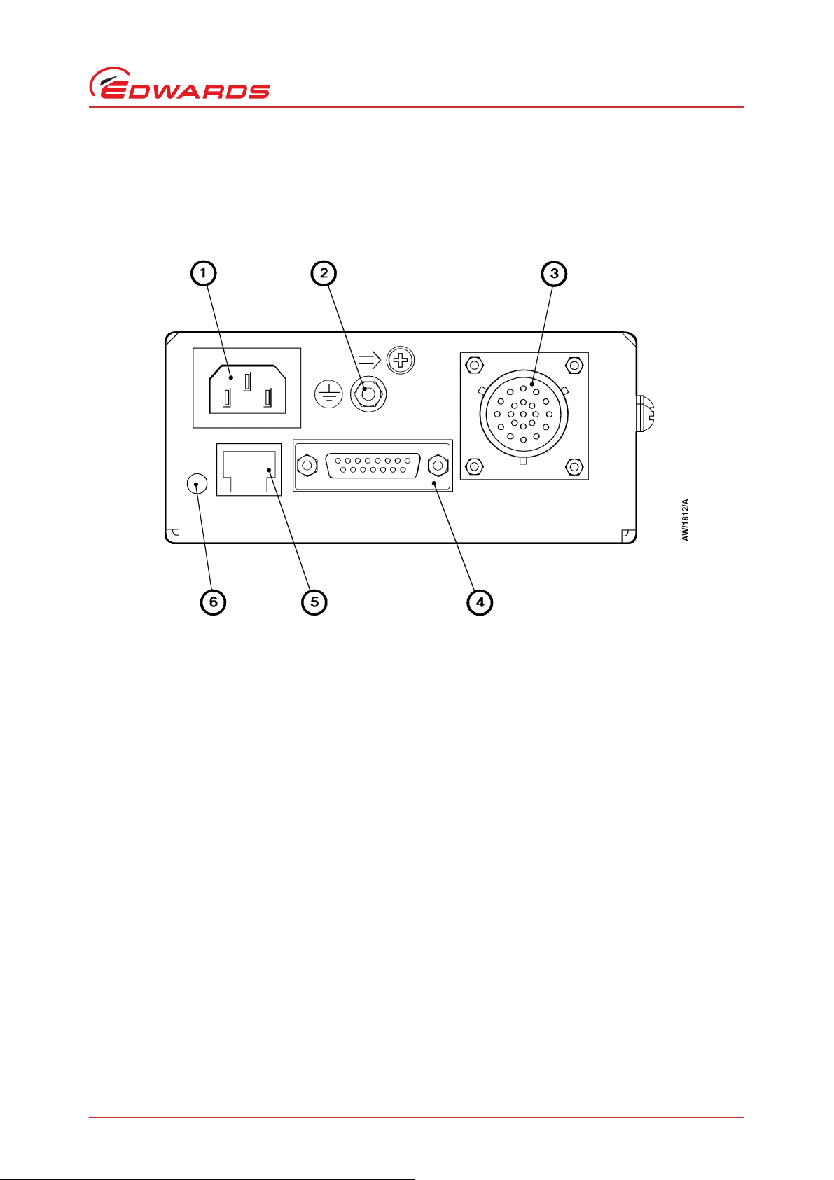
Figure 1 - Rear panel of the Controller (EXC100E shown)
1. Electrical supply connector
2. Earth (ground) stud
3. EXT pump connector
1
1
EXC100E only; the EXC100L has an
integral pump-to-controller cable
4. Logic interface connector
5. Active gauge connector
6. Normal LED
D396-20-880 Issue H
Introduction
© Edwards Limited 2015. All rights reserved. Page 7
Edwards and the Edwards logo are trademarks of Edwards Limited.
Page 14

D396-20-880 Issue H
This page has been intentionally left blank.
Page 8 © Edwards Limited 2015. All rights reserved.
Edwards and the Edwards logo are trademarks of Edwards Limited.
Page 15

D396-20-880 Issue H
2Technical data
2.1 Operating and storage conditions
Table 1 - Operating and storage conditions
Ambient operating temperature range 0 to 40 °C
Ambient storage temperature range -20 to 70 °C
Maximum ambient operating humidity 10 to 95% RH (non-condensing to DIN 4004 0)
Maximum operating altitude 3000 m
Cooling Natural convection
2.2 Mechanical data
Table 2 - Mechanical data
Dimensions See Figure 2
Mass
EXC100E 0.8 kg
EXC100L 1.0 kg
Enclosure protection IP20
Pollution degree EN61010, category 2
Technical data
2.3 Electrical data
Table 3 - Electrical data
Electrical supply
Voltage 90 to 264 V a.c., single-phase
Frequency 47 to 63 Hz
Maximum input power 220 VA
Peak inrush current 11 A at 110 V a.c.
40 A at 240 V a.c.
Fuse rating 2 A, type T 20 mm
Over-voltage transients EN61010, category 2
© Edwards Limited 2015. All rights reserved. Page 9
Edwards and the Edwards logo are trademarks of Edwards Limited.
Page 16

D396-20-880 Issue H
Technical data
2.4 EXT pump electrical output data
Table 4 - EXT pump electrical output data
Compatible EXT pumps EXT70, EXT250, EXT351
Maximum continuous output power 80 W
Maximum output voltage 53 V a.c. r.m.s.
Switching frequency 32 kHz
Nominal output frequency 600 Hz to 1.5 kHz
Maximum output frequency 1.07 x nominal
Standby frequency 70% of nominal
2.5 Logic interface
Table 5 - Logic interface data
Remote control signals
Control voltage: low (close) < 0.8 V d.c.
Control voltage: high (open) 4 to 24 V d.c.
Maximum input current (at 24 V) 80 A
Maximum output current (at 0 V d.c.) 160 A
Air-cooler electrical supply
Voltage range +20 to +26 V d.c.
Maximum output current 150 mA
Vent-valve electrical supply
Voltage range +16 to +26 V d.c.
Maximum output current 80 mA
Analogue output
Output voltage 0 to +10 V d.c. proportional to speed or power:
0 to 10 V 0 to 100% of pump speed, or
0 to 10 V 0 to 80 W motor power
Maximum output current 5 mA
TMP Normal and TMP Fail status outputs
Maximum output voltage (high) 26 V d.c.
Maximum output current
Vout (low) 0.8 V 20 mA
Vout (low) < 0.8 V (TTL level) 1 mA
TMP On status output
Logic high output voltage at 8 A4.12 V
Logic low output voltage at 42 A0.77 V
Page 10 © Edwards Limited 2015. All rights reserved.
Edwards and the Edwards logo are trademarks of Edwards Limited.
Page 17

D396-20-880 Issue H
2.6 Factory settings
Table 6 - Factory settings
Normal speed 80%
Internal Timer 8 min, enabled
Vent options See Table 9
Analogue output Speed output
2.7 Electrical connectors
Note: Do not connect voltages greater than 45 V to the logic interface. If you do, the Controller will not comply
with the low voltage safety recommendations of IEC 1010.
Table 7 - Electrical connectors
Electrical supply connector socket type CEE/IEC 320
Earth (ground) stud (on rear panel) M4
Active gauge connector
Signals on the connector pins See Figure 6 and Table 11
Socket type FCC68, 8-way
Manufacturer Western Electric
Maximum power 3 W
Logic interface connector 15-way sub-miniature ‘D’ type socket
Technical data
© Edwards Limited 2015. All rights reserved. Page 11
Edwards and the Edwards logo are trademarks of Edwards Limited.
Page 18

D396-20-880 Issue H
A. Rear view
B. Top view
C. Side view
1. Clearance for ventilation
2. Clearance for cables
3. Optional mounting plate
Technical data
Figure 2 - Dimensions (mm): EXC100E shown
Page 12 © Edwards Limited 2015. All rights reserved.
Edwards and the Edwards logo are trademarks of Edwards Limited.
Page 19

D396-20-880 Issue H
3 Installation
3.1 Unpack and inspect
Remove all packing materials and check the Controller. If the Controller is damaged, notify your supplier and the
carrier in writing within three days; state the Item Number of the Controller together with your order number and
your supplier’s invoice number. Retain all packing materials for inspection. Do not use the Controller if it is damaged.
If the Controller is not to be used immediately, store the Controller in suitable conditions, as described in Section 6.1.
3.2 Configure the Controller
3.2.1 Introduction
The Controller has four links which can be used to configure the Controller for your application: see Table 8. Each
link can be in one of two positions as shown in Figure 3 and described in Sections 3.2.2 and 3.2.4.
If you want to reconfigure the Controller, undo and remove the two screws (Figure 3, items 1) and remove the top
cover (2) of the Controller to access the links. Use the links as described in the following sections.
Installation
Table 8 - Configuration links
Link Use
LK1 Select speed or power analogue output
LK4 Enable or disable the Internal Timer
LK5 Select Vent on Stop or no Vent on Stop
LK6 Select Vent on Fail or no Vent on Fail
3.2.2 Select speed or power analogue output
Note: The Controller is supplied with link LK1 configured to provide the pump speed analogue output signal on
the logic interface.
Refer to Figure 3. To select the pump speed analogue output signal on the logic interface, insert link LK1 in the upper
position (5).
To select the pump power analogue output signal on the logic interface, insert link LK1 in the lower position (6).
© Edwards Limited 2015. All rights reserved. Page 13
Edwards and the Edwards logo are trademarks of Edwards Limited.
Page 20

D396-20-880 Issue H
Installation
3.2.3 Enable/disable the Internal Timer to monitor low pump speed
Notes: 1. If you pump a high gas load when the Internal Timer is enabled (link LK4 in the enabled position:
Figure 3, item 12), the EXT pump may stall before the Controller trips into Fail condition. Ensure that
oil which backstreams from the backing pipeline will not adve rsely affect your process. Disable the
Internal Timer to provide the greatest protection against backstreaming if a Fail condition occurs.
2. The Controller is supplied with the Internal Timer enabled.
Set link LK4 to enable or disable the use of the Internal Timer when the pump rotational speed falls to below 50% of
full rotational speed during operation (see Section 1.6.2):
Insert link LK4 in the active position (Figure 3, item 12) to enable the Timer.
The Internal Timer will then start as soon as the pump rotational speed falls to below 50% of full rotational
speed. If the pump speed remains below 50% of full rotational speed after the preset time, the Controller
will trip into the Fail condition.
Insert link LK4 in the not active position (Figure 3, item 11) to disable the Timer.
The Controller will then trip into the Fail condition as soon as the pump rotational speed falls to below 50%
of full rotational speed.
3.2.4 Vent options
Links LK5 and LK6 are used to select the vent-valve control options (refer to Section 1.5). Each of the links can be in
one of two positions: the link not active position and the link active p osition. Position the links to s elect the requ ired
vent options as shown in Table 9.
Note however, that if the electrical supply to the Controller fails, the Controller will always switch off the electrical
supply to the vent-valve when the EXT pump speed falls to below 50% of full speed (see Section 1.6.1).
Table 9 - Selection of vent-valve control options
Link positions
LK6 (Vent on Fail) LK5 (Vent on Stop)
not active not active Vent when the EXT pump speed falls to 50% of
not active active Ven t on Stop; vent when the EXT pump speed
*
active
active active Vent on Fa il and vent on Stop.
*
Link positions as supplied.
not active
*
Vent options
full speed after Stop is selected or a Fail
condition is detected.
falls to 50% of full speed after a Fail condition is
detected.
Vent on Fail; vent when the EXT pump speed
falls to 50% of full speed after Stop is selected.
Page 14 © Edwards Limited 2015. All rights reserved.
Edwards and the Edwards logo are trademarks of Edwards Limited.
Page 21

Figure 3 - Reconfigure the Controller (EXC100L shown)
1. Screw
2. Top cover
3. Fuse holder
4. Speed/power link: LK1
5. Link LK1 in speed configuration
6. Link LK1 in power configuration
7. Link LK6 not active: Vent On Fail not se lected
8. Link LK6 active: Vent On Fail selected
9. Link LK5 not active: Vent On Stop not selected
10.Link LK5 active: Vent On Stop selected
11.Link LK4 not act ive: Timer disabled
12.Link LK4 active: Timer enabled
D396-20-880 Issue H
Installation
© Edwards Limited 2015. All rights reserved. Page 15
Edwards and the Edwards logo are trademarks of Edwards Limited.
Page 22

D396-20-880 Issue H
CAUTION
WARNING
Installation
3.3 Fit the Controller
The Controller contains electrolytic capacitors and, under certain fault conditions, may emit
dangerous fumes. Ensure that the Controller is operated in a well-ventilated area.
You must allow the correct clearances for air circulation and you must fit the Controller onto a thermally
conductive surface. If you do not, the performance and reliability of the Controller may be affected at high
operating temperatures.
You must fit the Controller in a rack or cabinet. You can operate the Controller in a horizontal position or in a vertical
position with the side vents at the top.
When you fit the Controller, you must allow 15 mm clearance at the sides of the Controller for air circulation and
you must allow 75 mm clearance at the back of the Controller for the cables.
You must firmly fit the Controller onto a thermally conductive material, for example aluminium or steel. The location
of the bottom panel fixing-holes are shown in Figure 2.
3.4 Introduction to Controller electrical connections
When you make the electrical connections to the Controller described in the following sections, refer to Table 10 for
full details of the logic interface connections and refer to Figure 4 which shows a schematic diagram of the electrical
connections. You must provide suitable strain-relief on the cables which you fit to the Controller.
Table 10 - Logic interface pins
N/A
+
+
-
+
*
Signal type
Status
outputs
Control
input
Control
input
Supply
Supply
Analogue
output
Pin number Signal
1 TMP On (low when pump is on) N/A
7 TMP Fail (high when fail condition exists) N/A
8 Status output common N/A
15 TMP Normal (low when pump is at Normal speed)
3
4 -
11
4 -
10 RFI screen N/A N/A
5 Vent-valve electrical supply: 24 V +
13 Vent-valve control
6 Air-cooler electrical supply: 24 V +
14 Air-cooler electrical supply: 0 V -
9
2 -
*
+ = positive, - = negative, N/A = not applicable.
†
This output is only TTL compatible when the current drawn is < 1 mA. See Section 2 for more information.
‡
This supply line is raised to +24 V to de-energise the valve coil and vent the system.
Start/Stop: Close for Start
Standby: Close for Standby
‡
Pump speed or power
†
Polarity
Page 16 © Edwards Limited 2015. All rights reserved.
Edwards and the Edwards logo are trademarks of Edwards Limited.
Page 23

Figure 4 - Schematic diagram of Controller electrical connections
1. External electrical supply
2. Electrical supply connector
3. Earth (ground)
4. AIM active gauge
5. Active gauge connector
6. Logic interface connector
7. Vent-valve control (normally open)
1
8. TMP Fail (normally closed)
9. TMP Normal output (normally open)
1
10.Remote indicator equipment
11.Air-cooler
12.Vent-valve
13.External Standby switch
14.External Start/Stop switch
15.Speed/power indicator
1
These are solid-state switches in the Controller
A. Vacuum and control system
B. EXC Controller
L Live electrical supply
N Neutral electrical supply
E Earth (ground) electrical supply
D396-20-880 Issue H
Installation
© Edwards Limited 2015. All rights reserved. Page 17
Edwards and the Edwards logo are trademarks of Edwards Limited.
Page 24

D396-20-880 Issue H
WARNING
Installation
3.5 Connect the electrical supply
High voltages exist in the Controller when it is operating. Ensure that the Controller is earthed
(grounded) and observe all appropriate safety precautions for the safe installation and handling of
electrical equipment. If you do not, there will be a danger of injury or death to people by electric
shock.
You must use a suitable electrical supply cable to connect the Controller to the electrical supply. An electrical supply
cable is not supplied with the Controller, but is available as an accessory: refer to Section 7.3.1.
1. Connect the wires at one end of the electrical supply cable to a suitably rated and fused electrical supply; if
required, connect the wires to a suitably rated plug. Connect the wires as shown in Table 11.
2. Fit the connector on the other end of the electrical supply cable to the electrical supply connector on the front
of the Controller (see Figure 1).
Table 11 - Electrical supply cable wires
Wire colour Use
Green/yellow Earth (ground)
Brown Live (line )
Blue Neutral
3.6 Connect additional earth (ground) bonding (if required)
Protective earthing (grounding) for electrical safety of the Controller, EXT pump and accessories is provided by the
electrical supply cables and connectors and the pump-to-controller cable. However, additional earth (ground)
bonding may be required to improve the reliability of the system by reducing any effects of RFI (radio frequency
interference), particularly if the vacuum system is prone to high voltage discharges or other radio frequency
emissions.
Use good EMC (electromagnetic compatibility) practices and take note of the following EMC earthing (grounding)
guidelines to reduce the susceptibility of the system to RFI:
Connect the Controller, the EXT pump and the vacuum chamber to a common earth (ground) point on the
pumping system; this ‘star’ earth (ground) is typically in the electrical power distribution box.
Clamp the Controller earthing (grounding) terminal between the two lock-nuts provided on the earth
(ground) stud on the rear panel of the Controller.
Use suitable heavy duty cable or braid to ensure a low impedance bond to the earth (ground) point (typically
less than 0.1 for each leg of the star).
Use screened cable for all wiring to the logic interface connector. (The TAV5 vent-valve and the ACX Air
Cooler accessories are provided with screened cable.) Connect each screen to the Controller earth (ground)
stud to ensure that they are properly earthed (grounded).
3.7 Connect the EXT pump
If you have an EXC100L Controller, fit the connector on the end of the integral pump-to- controller cable to the
connector on the EXT pump.
If you have an EXC100E Controller, use a pump-to-controller cable (not supplied) to connect the Controller to the
EXT pump. Fit the connectors on the ends of the cable to the appropriate mating-halves on the rear of the Controller
and on the EXT pump.
Page 18 © Edwards Limited 2015. All rights reserved.
Edwards and the Edwards logo are trademarks of Edwards Limited.
Page 25

D396-20-880 Issue H
CAUTION
3.8 Connect an AIM Active Inverted Magnetron gauge (optional)
Use an Edwards Active gauge cable (available as an accessory: see Section 7.3.6) to connect an Edwards AIM Active
Inverted Magnetron Gauge to the Controller through the active gauge connector (Figure 1, item 5) on the rear of the
Controller.
If you want to connect another type of gauge to the Controller, connect the gauge to the logic interface: refer to
Section 3.9.
3.9 Connect the logic interface to your equipment
3.9.1 Introduction
Do not earth (ground) the logic interface 0 V line (pins 13 and 14). If you do, you will provide an earth (ground)
return path for any electrical fault in the pump-motor and this could damage the Controller or your control
equipment.
Use the appropriate pins on a suitable mating-plug (not supplied) for the logic interface connector to connect your
control equipment and accessories to the Controller, as described in the previous sections and as shown in Table 10
and Figure 4. We recommend that you use wire of 0.24 mm
2
(or smaller) cross-sectional area.
Installation
Alternatively, if you do not connect the Controller to your control equipment, link pins 3 and 4 in the mating-plug.
The EXT pump will then start to operate as soon as the electrical supply to the Controller is switched on and the pump
will stop when the electrical supply to the Controller is switched off.
3.9.2 Connect a vacuum gauge to the logic interface
You can connect an Edwards APG Active Pirani Gauge to the Controller so that the setpoint output of the gauge s ets
the Start/Stop input on the logic interface, to switch on the EXT pump. We recommend that you use the following
procedure:
1. Fit an active gauge connector to a suitable break-out box.
2. Connect wires from the break-out box to the logic interface on the Controller, as shown in Table 12.
Table 12 - APG to logic interface connections
APG connector
pin number
1
2
3
4
5
6
If you want to connect another type of gauge to the Controller, refer to the instruction manual supplied with your
gauge for information on the electrical connections to the gauge.
Logic interface
pin number
6
14
-
-
-
3
© Edwards Limited 2015. All rights reserved. Page 19
Edwards and the Edwards logo are trademarks of Edwards Limited.
Page 26

D396-20-880 Issue H
Installation
3.10 Adjust the Normal speed
Note: If you set the Normal speed to be more than 70% of full rotational speed, the TMP Normal output will go
high when you select Standby. The Controller is supplied with the Normal speed set to 80% of full rotational
speed.
You can adjust the Normal speed (at which the TMP Normal output goes low: see Section 1.4.4) between 65 and 95%
of full rotational speed.
Refer to Figure 5. To adjust the Normal speed, use a small screwdriver to turn the SETPOINT potentiometer (A).
Figure 5 also shows the approximate Normal speed settings for different potentiometer adjustments.
3.11 Adjust the Internal Timer
The Internal Timer can be adjusted between approximately 1 and 30 minutes. The Controller is supplied with the
Internal Timer adjusted to eight minutes (see Section 1.6.2).
To adjust the Internal Timer, use a small screwdriver to turn the TIMER potentiometer (B). Figure 5 also shows the
approximate timer settings for different potentiometer adjustments; these settings are only approximate. If the
timer setting is critical for your application, you must check the time and readjust the potentiometer as necessa ry,
until the correct time is obtained.
Page 20 © Edwards Limited 2015. All rights reserved.
Edwards and the Edwards logo are trademarks of Edwards Limited.
Page 27

Figure 5 - Reconfigure the Controller (EXC100L shown)
A. Normal speed potentiometer
B. Timer potentiometer
D396-20-880 Issue H
Installation
© Edwards Limited 2015. All rights reserved. Page 21
Edwards and the Edwards logo are trademarks of Edwards Limited.
Page 28

D396-20-880 Issue H
This page has been intentionally left blank.
Page 22 © Edwards Limited 2015. All rights reserved.
Edwards and the Edwards logo are trademarks of Edwards Limited.
Page 29

D396-20-880 Issue H
4 Operation
4.1 Start-up
Notes: 1. If you wish, you can start the backing pump and the EXT pump at the same time; the EXT pump will not
be damaged and can operate as an effective baffle. However, if the system pressure remains too high
for the EXT pump to reach 50% of full rotational speed in the preset time (set by the Internal Timer),
the Controller will trip into Fail condition: refer to Section 3.11 for adjustment of the Internal Timer.
2. The following sections assume that you will connect the Controller to your control equipment and use
the control input signals on the logic interface connector to operate the pumping system.
When Start is selected, the Controller will switch on the electrical supply to the EXT pump and the pump rotor will
start to accelerate.
Use the following procedure to start up your system. This procedure assumes that you will manually operate the ventvalve and the backing pump, however you can configure the Controller to automatically operate the vent-valve (refer
to Section 3.2.4).
1. Close the vent-valve (if fitted).
2. Start the backing pump.
Operation
3. Start the EXT pump: close the Start/Stop input on the logic interface (see Section 1.4.3).
4.2 Standby
To select Standby, close the Standby input on the logic interface (that is, ensure that the appropriate pins are linked:
see Section 1.4.3).
If you select Standby when the pump is operating, the speed of the pump will be reduced to the Standby speed. If
you select Standby before you switch the pump on, the pump will run up to Standby speed, not up to full speed.
4.3 Operation with high inlet pressure
If the EXT pump inlet pressure rises, the power supplied by the Controller to the pump-motor will increase to
counteract the gas frictional load. The pump rotational speed will remain constant until the Controller peak power
level is reached; beyond this power level, the speed of the pump will start to reduce.
If the pump speed falls to below 50% of its full rotational speed, the Controller may trip into Fail condition; this
depends on how you have configured the Controller (see Sections 1.6 and 3.2).
Refer to the EXT pump instruction manual for the maximum allowable inlet pressure, and refer to Section 2.4 for the
maximum Controller output power.
4.4 Operation with high pump temperature
Temperature sensors in the Controller and the EXT pump are monitored by the Controller. If the Controller detects
that the pump temperature is too high, the power supplied to the pump-motor is reduced; the pump may not
therefore be able to maintain full rotational speed if it is too hot.
If the pump speed falls to below 50% of its full rotational speed, the Controller may immediately trip into Fail
condition, or trip into Fail condition after a set time; this depends on how you have configured the Controller (see
Sections 1.6 and 3.2).
Refer to the EXT pump instruction manual for the pump operating temperature ranges.
© Edwards Limited 2015. All rights reserved. Page 23
Edwards and the Edwards logo are trademarks of Edwards Limited.
Page 30

D396-20-880 Issue H
WARNING
Operation
4.5 Normal shutdown
Use the following procedure to shut down your system. This procedure assumes that you will manually operate the
vent-valve and the backing pump, however you can configure the Controller to automatically operate the vent-valve
(refer to Section 3.2.4). Refer to the Instruction Manual for the EXT pump for details of the maximum allowable vent
rate.
1. Select Stop: open the Start/Stop input on the logic interface connector (see Section 1.4.3).
2. Open the vent-valve before the EXT pump speed is below 50% of full rotational speed.
3. Switch off the backing pump.
4.6 Automatic shutdown after Fail condition
If the Start/Stop control signal on the logic interface connector is set to Start, the Controller will
automatically restart the EXT pump when the electric al supply is restored after an electrical
supply failure. Ensure that people cannot be injured by the rotating rotor blades of the EXT pump.
The Controller will automatically switch off the electrical supply to the EXT pump if the Controller trips into Fail
condition (see Section 1.6).
The operation of the vent-valve in all Fail conditions depends on how you have configured the Controller: refer to
sections 1.6 and 3.2.
4.7 Reset the Controller after Fail condition
To reset a Fail condition, open the Start/Stop input on the logic interface for at least 300 ms and then close the input.
4.8 Electrical supply failure
If the electrical supply to the Controller fails when the EXT pump is rotating:
The motor of the EXT pump is used as a generator and the electrical supplies for the vent-valve, air-cooler
and AIM gauge (if connected) and the associated control logic are maintained until the pump speed falls to
50% of full rotational speed, then the electrical supplies are switched off.
The Controller will then shut down.
Page 24 © Edwards Limited 2015. All rights reserved.
Edwards and the Edwards logo are trademarks of Edwards Limited.
Page 31

D396-20-880 Issue H
WARNING
5Maintenance
5.1 Safety
Obey the safety instructions given below and take note of appropriate precautions. If you do not,
you can cause injury to people and damage to equipment.
A suitably trained and supervised technician must maintain the Controller.
Isolate the Controller and other components in the pumping system from the electrical supply so that they
cannot be operated accidentally.
Dispose of components safely (see Section 6.2).
5.2 Replace a fuse
5.2.1 Introduction
Maintenance
If the electrical supply fuse fails immediately after you have replaced it, determine the cause of the failure and
rectify the fault before you use the Controller.
5.2.2 Replace the electrical supply fuse
1. Refer to Figure 3. Undo and remove the two screws (1) and remove the top cover (2) of the Controller.
2. Remove the fuse holder (3), remove and discard the failed fuse.
3. Insert a new fuse of the correct rating (refer to Section 2.3) and refit the fuse holder.
4. Refit the top cover (2) and secure with the two scre ws (1).
5.3 Clean the Controller
If necessary, use a soft dry cloth to clean the exterior of the Controller.
If you need to clean the interior of the Controller, we recommend that you return the Controller to your supplier or
your nearest Edwards Service Centre.
5.4 Fault finding
If the Controller shuts down because of Fail condition, refer to the ap propriate sections of this manual to determine
the cause of the Fail condition. If necessary, refer to the appropriate fault finding section of the instruction ma nual
supplied with the EXT pump.
© Edwards Limited 2015. All rights reserved. Page 25
Edwards and the Edwards logo are trademarks of Edwards Limited.
Page 32

D396-20-880 Issue H
This page has been intentionally left blank.
Page 26 © Edwards Limited 2015. All rights reserved.
Edwards and the Edwards logo are trademarks of Edwards Limited.
Page 33

D396-20-880 Issue H
WARNING
6 Storage and disposal
6.1 Storage
Fit protective covers over the electrical connections and store the Controller in clean dry conditions until required.
When required for use, prepare and install the Controller as described in Section 3 of this manual.
6.2 Disposal
Do not incinerate the Controller. If you do, you may cause injury to people.
Dispose of the Controller and any components safely in accordance with all local and national safety and
environmental requirements.
Storage and disposal
Do not incinerate the Controller. If the Controller is heated to very high temperatures, dangerous gases may be
emitted and internal components may explode.
© Edwards Limited 2015. All rights reserved. Page 27
Edwards and the Edwards logo are trademarks of Edwards Limited.
Page 34

D396-20-880 Issue H
This page has been intentionally left blank.
Page 28 © Edwards Limited 2015. All rights reserved.
Edwards and the Edwards logo are trademarks of Edwards Limited.
Page 35

D396-20-880 Issue H
7 Service and accessories
7.1 Introduction
Edwards products, spares and accessories are available from Edwards companies in Belgium, Brazil, China, France,
Germany, Israel, Italy, Japan, Korea, Singapore, United Kingdom, U.S.A and a world-wide network of distributors.
The majority of these centres employ Service Engineers who have undergone comprehensive Edwards training
courses.
Order spare parts and accessories from your nearest Edwards company or distributor. When you order, state for each
part required:
Model and Item Number of your equipment
Serial number
Item Number and description of part.
7.2 Service
Edwards products are supported by a world-wide network of Edwards Service Centres. Each Service Centre offers a
wide range of options including: equipment decontamination; service exchange; repair; rebuild and testing to factory
specifications. Equipment which has been serviced, repaired or rebuilt is returned with a full warranty.
Service and accessories
Your local Service Centre can also provide Edwards engineers to support on-site maintenance, service or repair of
your equipment.
For more information about service options, contact your nearest Service Centre or other Edwards company.
7.3 Accessories
7.3.1 Electrical supply cable
You must use a suitable electrical supply cable to connect the Controller to your electrical supply. An electrical
supply cable is not supplied with the Controller.
Cable Item Number
Electrical supply cable (2 m length, unterminated) D385-01-102
© Edwards Limited 2015. All rights reserved. Page 29
Edwards and the Edwards logo are trademarks of Edwards Limited.
Page 36

D396-20-880 Issue H
Service and accessories
7.3.2 Pump-to-controller cable
A pump-to-controller cable must be used with each pump. It is not supplied with the EXT pump or with the EXC100E
Controller. The following cables are available:
Cable Item Number
Pump-to-controller cable, 1 m D396-18-010
Pump-to-controller cable, 3 m D396-18-030
Pump-to-controller cable, 5 m D396-18-050
Pump-to-controller cable (OEM
*
The OEM cable is supplied with a separate connector so that you can fit the cable through a
bulkhead, if required.
7.3.3 BX bakeout band
A BX bakeout band accelerates the degassing of the pump to enable it to achieve lower pressures. It may also be used
to protect the pump from condensation of contaminants. The bakeout bands are available in 110-120 V or 220-240 V
versions. You must provide an external electrical supply to power the bakeout band; you cannot power it from the
Controller.
*
), 5 m
D396-20-325
Bakeout band Voltage Item Number
BX70 110 V B580-52-040
BX70 240 V B580-52-060
BX250 110 V B580-52-041
BX250 240 V B580-52-061
BX351 110 V B580-52-042
BX351 240 V B580-52-062
7.3.4 TAV vent-valve
A solenoid-operated vent-valve is available for system venting. The valve is 24 V d.c. 2 W, normally-open, and can
be operated automatically from the EXC Controller. The solenoid-valve is fitted in place of the manual vent-valve,
or alternatively can be fitted with an adaptor (supplied with the valve) and used with any suitable NW10 flanged port
on your vacuum system.
Vent-valve Item Number
TAV vent-valve B580-66-010
Page 30 © Edwards Limited 2015. All rights reserved.
Edwards and the Edwards logo are trademarks of Edwards Limited.
Page 37

D396-20-880 Issue H
7.3.5 ACX air-cooler
An ACX air-cooler can be fitted to the EXT pump and can be operated automatically from the Controller. However,
please refer to Section 3 of the instruction manual for the EXT pump to check the suitability of air cooling in a
particular application.
Air-cooler Item Number
ACX70 B580-53-050
ACX250 B580-53-150
ACX350/500 B580-53-200
7.3.6 Active vacuum gauges
Examples of suitable gauges and accessories which you can connect to the EXC Controllers are listed below. Note that
you can only connect an AIM gauge directly to the active gauge connector on the Controller; you mus t connect other
gauges through the logic interface: refer to Section 3.9.
Description Item Number
Service and accessories
AIM-S-NW25 Active Inverted Magnetron Gauge D145-45-000
AIM-SL-NW25 Active Inverted Magnetron Gauge D145-48-000
APG-M-NW16 Active Pirani Gauge D021-71-000
APG-L-NW16 Active Pirani Gauge D021-73-000
ATC-E Active Thermocouple Gauge D351-08-000
1
ATC-D
/8 inch NPT Thermocouple Gauge Tube D351-12-000
1
ATC-M
Active Gauge Cable, 0.5 m long D400-01-005
Active Gauge Cable, 1 m long D400-01-010
Active Gauge Cable, 3 m long D400-01-030
/8 inch NPT Thermocouple Gauge Tube D351-13-000
© Edwards Limited 2015. All rights reserved. Page 31
Edwards and the Edwards logo are trademarks of Edwards Limited.
Page 38

D396-20-880 Issue H
This page has been intentionally left blank.
Page 32 © Edwards Limited 2015. All rights reserved.
Edwards and the Edwards logo are trademarks of Edwards Limited.
Page 39

D396-20-880 Issue H
8 Engineering diagrams
To assist in fault finding (refer to Section 5.4), the connections between the Controller and the EXT pump are shown
in Figure 6.
The Active Gauge connector (which is specific to the EXC Controller) is shown in Figure 7.
Engineering diagrams
© Edwards Limited 2015. All rights reserved. Page 33
Edwards and the Edwards logo are trademarks of Edwards Limited.
Page 40

D396-20-880 Issue H
A. EXT pump
B. EXT connector on cable
C. EXC connector on cable
1
D. EXC Controller
1
EXC100E controller only; the
EXC100L has an integral cable
1. DC motor
2. Speed set resistor
3. Hall effect device 1
4. Hall effect device 2
5. Hall effect device 3
6. Pump temperature sensor
Engineering diagrams
Figure 6 - EXC Controller to EXT pump connections
Page 34 © Edwards Limited 2015. All rights reserved.
Edwards and the Edwards logo are trademarks of Edwards Limited.
Page 41

Figure 7 - Active gauge connector pins
Table 13 - Active gauge connector pins
D396-20-880 Issue H
Engineering diagrams
Pin Signal
1 Power supply +24 V d.c.
2 Power supply 0 V d.c.
3Not used
4 Gauge identification signal
5Not used
6Not used
7 TMP Normal status output
8Not used
© Edwards Limited 2015. All rights reserved. Page 35
Edwards and the Edwards logo are trademarks of Edwards Limited.
Page 42

D396-20-880 Issue H
This page has been intentionally left blank.
Page 36 © Edwards Limited 2015. All rights reserved.
Edwards and the Edwards logo are trademarks of Edwards Limited.
 Loading...