

Page 1

Instruction Manual
Equipment Support Toolkit (EST)
D372-17-880
Issue C
Description Item Number
Equipment Support Toolkit (EST) D372-19-650D
Original Instructions
Page 2

This page has been intentionally left blank.
Page 3

D372-17-880 Issue C
Contents
Section Page
1 Introduction ....................................................................................... 1
1.1 Scope and definitions ................................................................................................... 1
1.2 Introduction .............................................................................................................. 1
2 Installation ......................................................................................... 3
2.1 Computer requirements ................................................................................................ 3
2.2 Installing the EST software application .............................................................................. 3
2.3 Removing EST from your system ....................................................................................... 4
2.4 Registering and activating your product ............................................................................. 4
2.5 Establish communications between EST and equipment .......................................................... 6
3 Equipment support toolkit - main features ................................................. 11
4 Using the monitoring tools .................................................................... 15
4.1 Overview .................................................................................................................16
4.2 Equipment detection ................................................................................................... 16
4.3 The Alert Handler ....................................................................................................... 17
4.4 Equipment Control ...................................................................................................... 18
4.5 Viewing parameters using the gauge tool ........................................................................... 18
4.6 Parameter message monitoring .......................................................................................20
4.7 Reading system serial numbers ....................................................................................... 21
4.8 Viewing alert setpoints ................................................................................................22
4.9 Using the Parameter Trend Viewer (live data graphing) .........................................................22
Contents
5 The Configuration Handler .................................................................... 25
5.1 Selecting the Configuration Handler ................................................................................. 25
5.2 Configuration Handler toolset ........................................................................................25
5.3 Configuration Handler - creating a new folder .....................................................................26
5.4 Configuration Handler - viewing a configuration set ..............................................................26
5.5 Configuration Handler - renaming a set ............................................................................. 27
5.6 Configuration Handler - deleting a set ..............................................................................28
5.7 Configuration Handler - duplicating a set ........................................................................... 28
5.8 Configuration Handler - comparing a set ........................................................................... 28
5.9 Configuration Handler - importing a set ............................................................................ 29
5.10 Configuration Handler - acquiring configuration data ............................................................ 31
5.10.1 Acquiring data from equipment ......................................................................................31
5.10.2 Acquiring data from a TIM Recipe Handler .........................................................................35
5.11 Configuration Handler - applying configuration data .............................................................36
5.11.1 Applying a Configuration Set ..........................................................................................37
5.11.2 Applying Sets to a TIM Recipe Handler ..............................................................................40
5.12 Configuration Handler - Recipe Handler Utilities .................................................................. 42
6 The Data Logger ................................................................................ 45
6.1 Retrieving data using the Internal Logger Utility ..................................................................45
6.2 Exporting Internal logged data using ‘Export Logged Data Sets’ ................................................ 46
6.3 Deleting Sets of logged data .......................................................................................... 48
7 Selecting display unit preferences ........................................................... 49
8 XML equipment data synchronisation ........................................................ 51
9 The Equipment Clock Synchronisation tool ................................................. 53
cg/04/13
© Edwards Limited 2017. All rights reserved. Page i
Edwards and the Edwards logo are trademarks of Edwards Limited.
Page 4

D372-17-880 Issue C
Contents
10 View/change the ethernet settings .......................................................... 55
11 Service tools ..................................................................................... 57
11.1 Device defaulter ........................................................................................................57
11.2 TIM/ AIM/ iTIM/ MicroTIM I/O Viewer ............................................................................... 58
11.3 Zero Sensors .............................................................................................................58
12 The Help Menu .................................................................................. 59
12.1 Help > About ............................................................................................................. 59
12.2 Help > Licence .......................................................................................................... 60
13 Troubleshooting ................................................................................. 61
For return of equipment, complete the HS Forms at the end of this manual.
Illustrations
Figure Page
1 Removing EST from your system ....................................................................................... 4
2 Registration screen ...................................................................................................... 5
3 Mail details and security code ......................................................................................... 5
4 Activation code window ................................................................................................ 6
5 Licence validation ....................................................................................................... 6
6 PLF RS232 communications windows (initial settings) ............................................................. 7
7 Serial communication settings ......................................................................................... 8
8 Detected equipment (serial) ........................................................................................... 8
9 Adding Ethernet PLF communications ................................................................................ 9
10 Setting the IP address on a Windows PC ............................................................................10
11 Equipment list in EST window ........................................................................................ 10
12 Typical EST main view (iGX pump connected) .....................................................................11
13 EST menus ............................................................................................................... 12
14 Device information pop-up window ..................................................................................12
15 Detected equipment icon ............................................................................................. 12
16 Detected equipment, system controller example .................................................................13
17 The monitoring menu ..................................................................................................15
18 Example overview ......................................................................................................16
19 Alert Handler (maximised) ............................................................................................17
20 Alert Handler (minimised) .............................................................................................17
21 Alert message information ............................................................................................17
22 Alert over (coloured text on white background and end time shown) .........................................18
23 Equipment control ...................................................................................................... 18
24 Typical gauge pane view (iF400 default selection) ................................................................19
25 Gauges - select parameters ...........................................................................................20
26 Parameter message monitor .......................................................................................... 20
27 Serial number viewer .................................................................................................. 21
28 Setpoint viewer .........................................................................................................22
29 Parameter trend view ..................................................................................................23
30 Select setpoint limits ...................................................................................................23
31 Selecting the Configuration Handler ................................................................................. 25
32 EST Configuration Handler toolbar ...................................................................................25
33 EST Configuration Handler, tool selection drop down list ........................................................ 26
34 Creating a new folder .................................................................................................. 26
35 Viewing a set ............................................................................................................27
36 Compare Sets, compare sets for comparison .......................................................................28
Page ii © Edwards Limited 2017. All rights reserved.
Edwards and the Edwards logo are trademarks of Edwards Limited.
Page 5

D372-17-880 Issue C
37 Importing a Configuration Set, select source folder .............................................................. 29
38 Importing a Configuration Set, source folder selected ........................................................... 29
39 Importing a Configuration Set, select set for import ............................................................. 30
40 Importing a Configuration Set, confirm import ....................................................................30
41 Importing a Configuration Set, import successful .................................................................31
42 Select acquired data source (equipment) ...........................................................................32
43 Choose configuration items ...........................................................................................33
44 Individual configuration items selected ............................................................................. 33
45 Acquired data report ................................................................................................... 34
46 Naming an acquired set ................................................................................................ 34
47 Select acquired data source (Recipe Handler) .....................................................................35
48 Acquire data from TIM, choose equipment type ................................................................... 35
49 Acquire data from TIM, choose items ............................................................................... 36
50 Apply Set to equipment, selecting a set ............................................................................37
51 Apply Set, select equipment (system) as destination ............................................................. 38
52 Apply Set, check offset ................................................................................................ 38
53 Apply Set, display contents ...........................................................................................39
54 Apply Set to equipment ................................................................................................ 39
55 Select TIM Recipe Handler ............................................................................................40
56 View TIM Recipe Handler contents (TIM/iTIM only) ...............................................................41
57 View MicroTIM Recipe Handler contents ............................................................................42
58 MicroTIM and TIM/iTIM Recipe Handler Utility, example views .................................................43
59 Internal Logger Utility start screen .................................................................................. 45
60 Internal Logger Utility, enter log file name and description .....................................................45
61 Internal Logger Utility, select internal log ......................................................................... 46
62 Internal Logger Utility, acquiring internal logs .................................................................... 46
63 Selecting a logged data set for export ..............................................................................47
64 Choose a name and location for the exported set ................................................................. 47
65 Deleting logged data ...................................................................................................48
66 Unit Preference Selection (default shown) .........................................................................49
67 XML synchronisation start screen .....................................................................................51
68 Establish internet connection .........................................................................................51
69 Checking/updating equipment XML files ............................................................................ 52
70 XML synchronisation .................................................................................................... 52
71 Clock Synchronisation tool ............................................................................................53
72 Set date ..................................................................................................................53
73 View/change ethernet settings .......................................................................................55
74 Device defaulter ........................................................................................................57
75 TIM/ AIM/ iTIM/ MicroTIM I/O Viewer ............................................................................... 58
76 Zero Sensors .............................................................................................................58
77 Help About pane ........................................................................................................ 59
78 Licence Manager pane .................................................................................................60
Contents
© Edwards Limited 2017. All rights reserved. Page iii
Edwards and the Edwards logo are trademarks of Edwards Limited.
Page 6

D372-17-880 Issue C
Contents
Associated publications
Publication title Publication number
Vacuum Pump and Vacuum System Safety P400-40-100
Page iv © Edwards Limited 2017. All rights reserved.
Edwards and the Edwards logo are trademarks of Edwards Limited.
Page 7

D372-17-880 Issue C
CAUTION
WARNING
1Introduction
1.1 Scope and definitions
This manual provides installation and operating instructions for the Edwards Equipment Support Toolkit (abbreviated
to 'EST') software. This software must be used in accordance with this manual.
Read this manual before installing and using the EST software. Important safety information is highlighted as
WARNING and CAUTION instructions; these instructions must be obeyed. The use of WARNINGS and CAUTIONS is
defined below.
Warnings are given where failure to observe the instruction could result in injury or death to
people.
Cautions are given where failure to observe the instruction could result in damage to the equipment, associated
equipment and process.
Introduction
Throughout this manual, page and figure numbers are sequential.
1.2 Introduction
The EST software is a PC based, Microsoft™ Windows compatible program that provides a user with enhanced control
and monitoring of an attached Edwards dry pumping system.
EST can be used with the PDT or system connection of the following range of Edwards products:
iXH, iXL, iXM, GXS, pXH
iGX, GX, pHMB
IPX, EPX with End User Module
iL, iH (MK2 and later)
iF
Axiom
Multiple pump systems using the System Controller and combinations of the above pumps
© Edwards Limited 2017. All rights reserved.© Edwards Limited 2017. All rights reserved. Page 1
Edwards and the Edwards logo are trademarks of Edwards Limited.
Page 8

D372-17-880 Issue C
This page has been intentionally left blank.
Page 2 © Edwards Limited 2017. All rights reserved.
Edwards and the Edwards logo are trademarks of Edwards Limited.
Page 9

D372-17-880 Issue C
2 Installation
2.1 Computer requirements
The following hardware and software will be required to run the EST software with satisfactory performance:
Processor Processor 1.5 GHz or better
Operating System Microsoft™ Windows 10 / 8 / 7 / XP
(32-bit or 64-bit OS supported)
RAM 2 GB RAM minimum
HDD Space 10% of free Hard Drive space
(minimum 5 GB)
Graphics 1024x768 Graphics minimum
(1280x1024 or better recommended)
EST does not support the following pre-Windows XP operating Systems: Windows 98, Windows 2000/ME, Windows
Vista.
Installation
EST is not compatible with the Apple™ MAC OS.
Edwards cannot be held responsible for any problems resulting from the use of EST with an operating system other
than Windows 10 / 8 / 7 or XP.
2.2 Installing the EST software application
Note: To install and use EST, the user is required to have Local Administrator Rights. If in doubt please contact
your IT department.
The EST application (D37219650) can be downloaded from the Internet website:
www.upgrades.edwardsvacuum.com/producttemplate/en/index.html
Customers purchasing EST are supplied with a kit that includes a card with a serial number code. This unique code
must be used to register each installation of EST prior to first use. Detailed instructions for registering EST are
provided later in this manual.
Ensure that all other applications are closed down and no error messages are present. If installing over a previous
version of EST, it is recommended that you go to Control Panel > Add or Remove Programs and delete all previous
versions of EST.
Copy the EST setup file to a local folder on your PC via your Internet browser and then run it.
EST setup performs a local user install, meaning each user has the to install it on a a given PC.
Follow the on-screen instructions to complete the installation.
© Edwards Limited 2017. All rights reserved.© Edwards Limited 2017. All rights reserved. Page 3
Edwards and the Edwards logo are trademarks of Edwards Limited.
Page 10
D372-17-880 Issue C
Installation
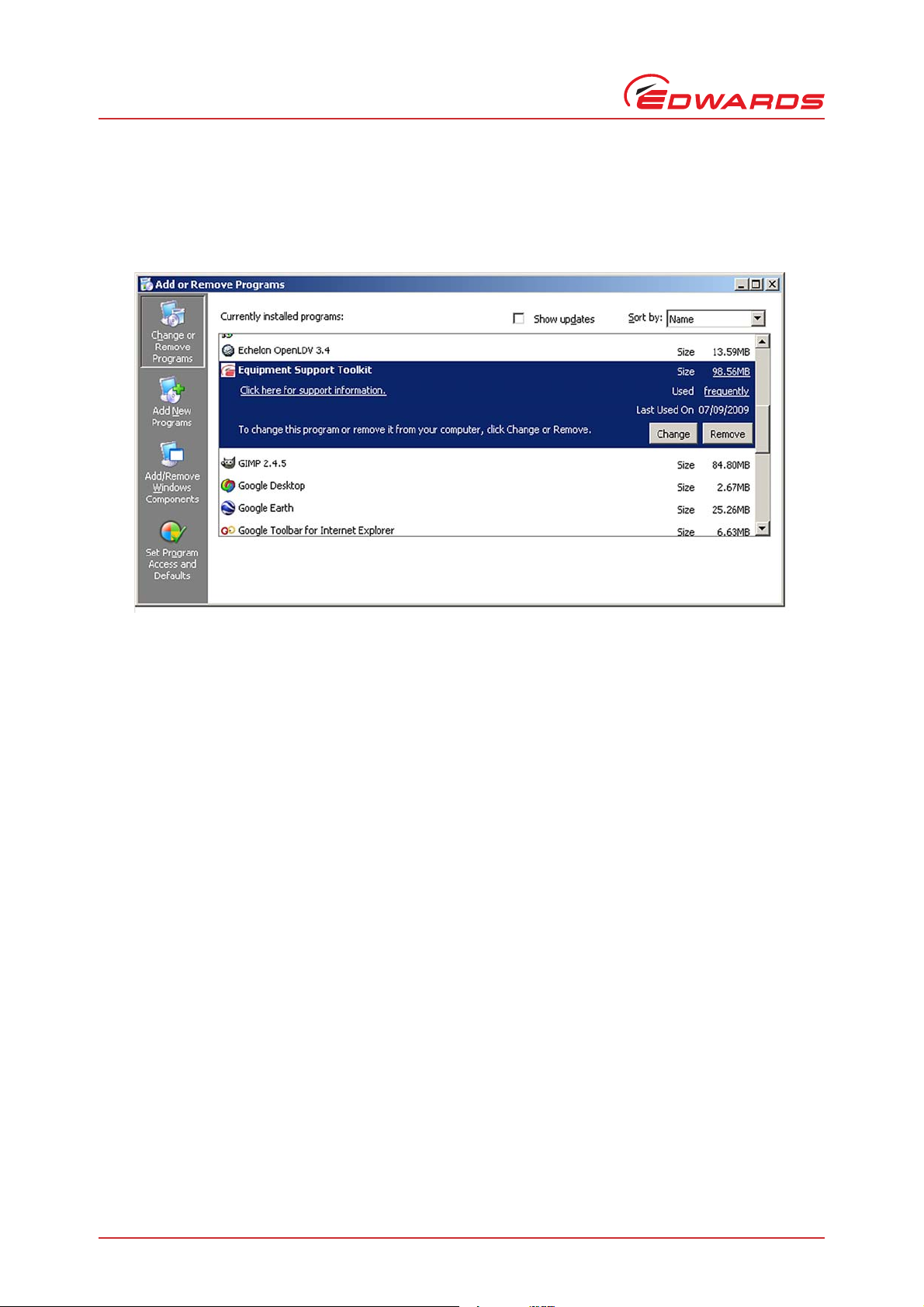
2.3 Removing EST from your system
EST can be removed from your system by going to the 'Add or Remove Programs' utility on the Control Panel.
Figure 1 - Removing EST from your system
2.4 Registering and activating your product
Before using EST, the package must be registered and activated via email. The EST kit contains a card that has a
unique serial number. The serial number is used by Edwards to identify your personal copy of EST. The Licence
Agreement with Edwards Limited permits one instance of EST to be installed per serial number. After installation,
the card with the serial number should be kept in a secure place.
To register and activate your copy of EST, go to Start, Programs, Edwards Applications and select the Equipment
Support Toolkit package. On running EST for the first time, the following Registration and Activation sequence will
be initiated:
Page 4 © Edwards Limited 2017. All rights reserved.
Edwards and the Edwards logo are trademarks of Edwards Limited.
Page 11
D372-17-880 Issue C
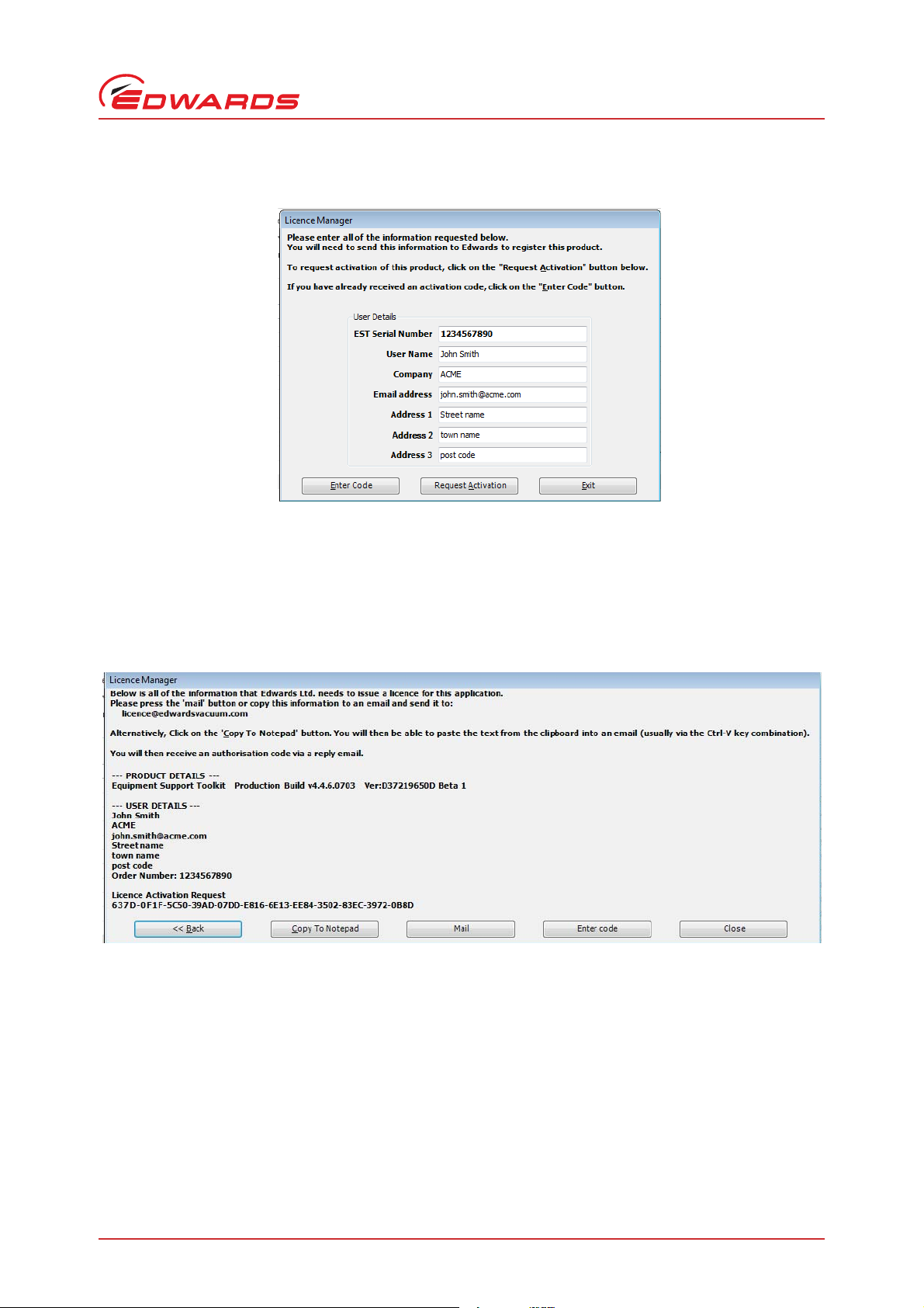
Figure 2 - Registration screen
The registration screen requires the user to enter the serial number from the EST kit card and full address details.
To enable the 'Request Activation Code' button, every line of the address details must be completed. It is important
that the user name and address details are entered correctly as the information is used by Edwards Limited to inform
users of product updates.
Installation
Click on the 'Request Activation Code' button to proceed.
Figure 3 - Mail details and security code
If you are installing EST on a PC with email capability that is connected to the internet, use the 'Mail' button to send
your registration details and security code to the Licence Mailbox:-
Licence@edwardsvacuum.com
If you do not have access to email from the EST host PC, use the 'Copy Data to Clipboard' to paste the information
into a text document. The document can then be copied onto another PC and e-mailed to the Licence Mailbox above.
Note: The Licence Mailbox at Edwards is administered manually. A response to your request will usually be made
within 24 hours but can take longer at weekends or when National holidays occur.
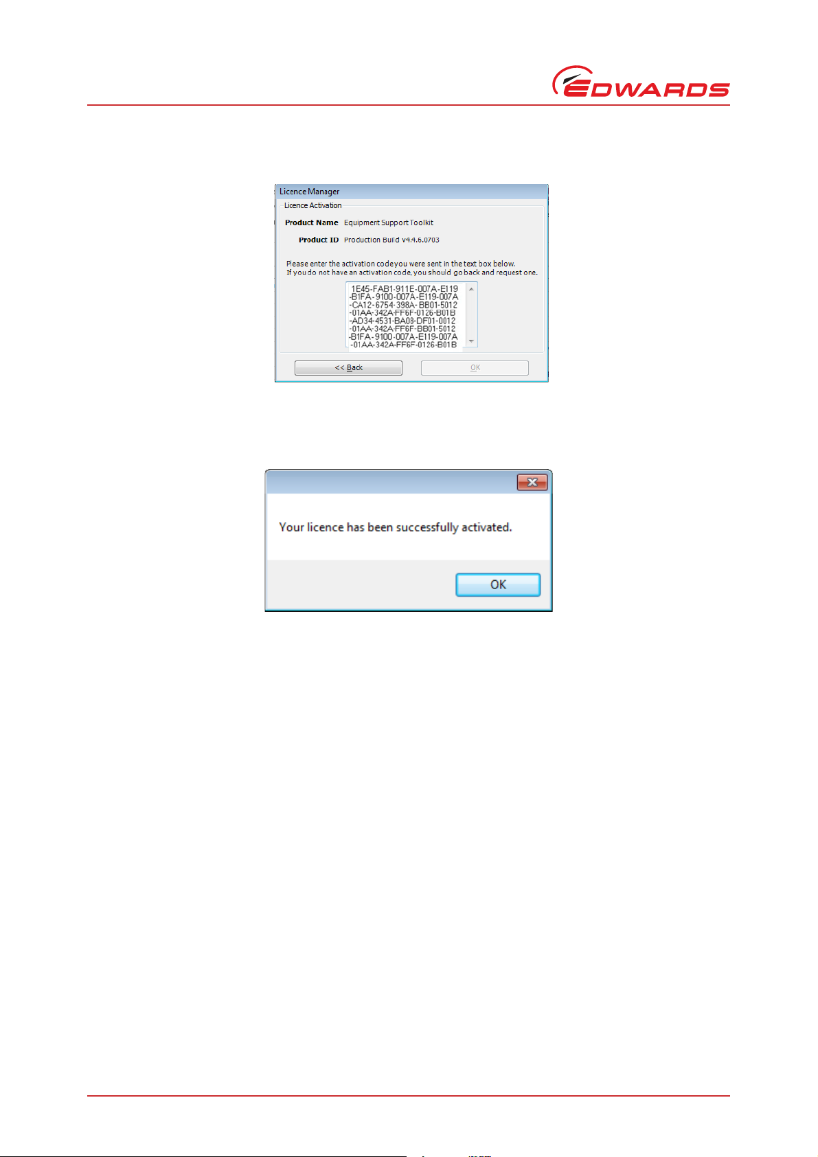
Upon receiving the activation code, click on 'Enter Code' and type or paste the number into the space provided as
shown below:
© Edwards Limited 2017. All rights reserved.© Edwards Limited 2017. All rights reserved. Page 5
Edwards and the Edwards logo are trademarks of Edwards Limited.
Page 12
D372-17-880 Issue C
Installation
Click on OK.
Figure 4 - Activation code window
Figure 5 - Licence validation
Click on 'OK'. The Equipment Support Toolkit is now ready for use.
Note: The application will restart after the registration process is complete.
2.5 Establish communications between EST and equipment
Connection to compatible Edwards equipment can be achieved using the USB to 5-way XLR (RS232 Serial) Lead - Part
No. D49951139. This cable is supplied as part of the USB Pump RS232 Interface Kit, part no. D372-15-805. The package
is normally supplied as part of the Equipment Support Toolkit bundle.
Windows will attempt to install the USB driver automatically soon after the USB cable is first plugged in. If this is
unsuccessful please refer to the detailed instructions for setting up and using the cable, plus USB drivers, that are
available on the Edwards Software Downloads website:
http://upgrades.edwardsvacuum.com/producttemplate/en/est.shtml
Note: iH pre mk5 and EPX End User Module have an RJ12 connector, the following conversion cable is required:
D37370726 PDT ADAPTOR,RJ12 PLG/5W XLR SKT
The cable is also included as part of the package 'USB Pump RS232 Interface Kit' (Edwards Item number D37215805).
For pumps that are equipped with a LON port only, (iQ, iL, iPX), please contact Edwards for further information.
The cable and drivers should be installed before continuing with this section.
Connection to compatible Edwards equipment can be also achieved via Ethernet TCP/IP communications, using
standard RJ45 to RJ45 patch cable.
Page 6 © Edwards Limited 2017. All rights reserved.
Edwards and the Edwards logo are trademarks of Edwards Limited.
Page 13
D372-17-880 Issue C
Communications between EST and the connected equipment utilise an Edwards® proprietary protocol named 'Pump
Local Format' (or PLF).
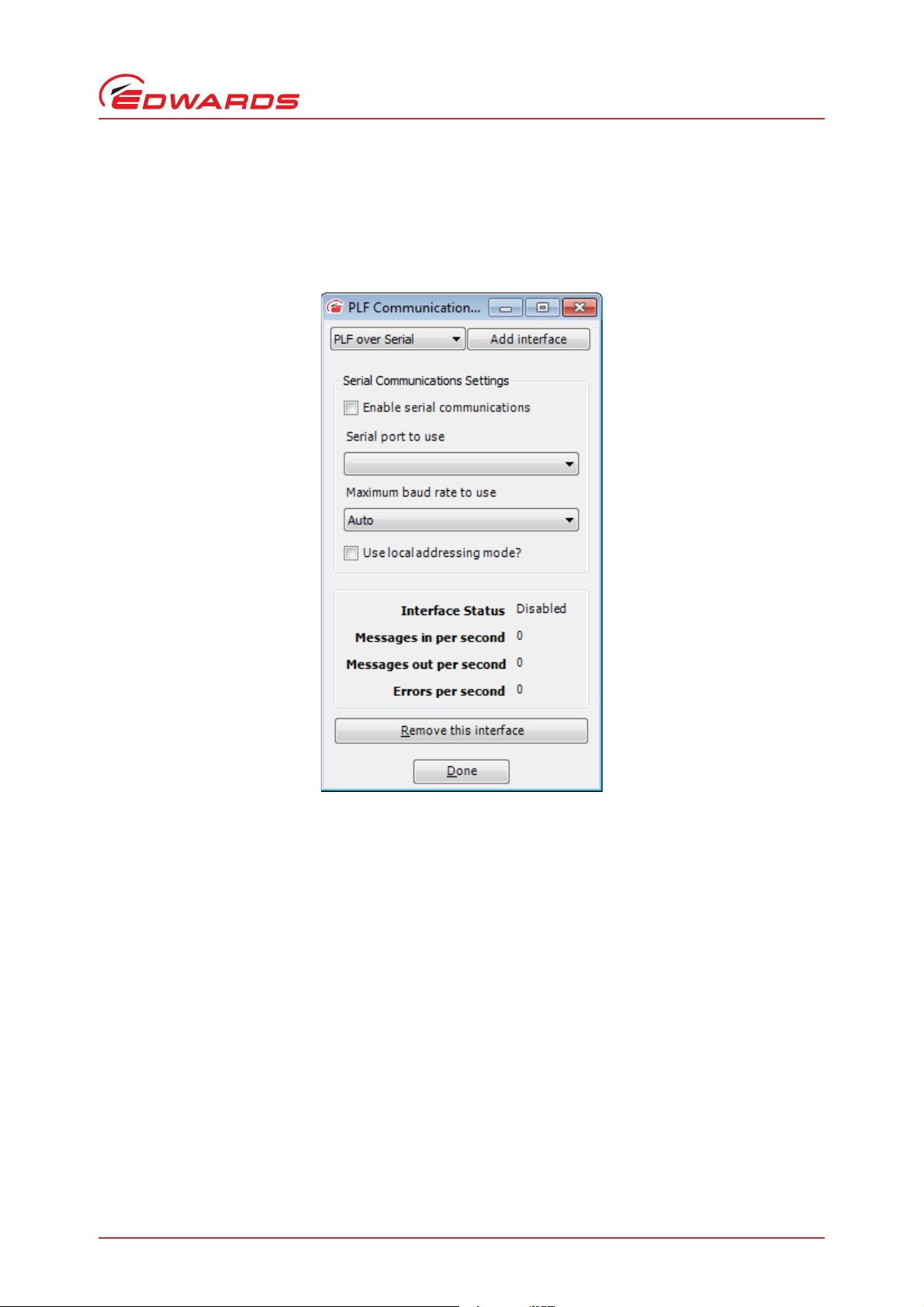
To configure PLF communications, launch EST and select the 'Options' menu. Select the utility 'PLF Communications
Settings'
Figure 6 - PLF RS232 communications windows (initial settings)
Installation
Upon opening the PLF Communications Settings window for the first time, settings panes for both LON and serial
communications will be displayed.
To enable your communications hardware, proceed as follows:
© Edwards Limited 2017. All rights reserved.© Edwards Limited 2017. All rights reserved. Page 7
Edwards and the Edwards logo are trademarks of Edwards Limited.
Page 14
D372-17-880 Issue C
Installation
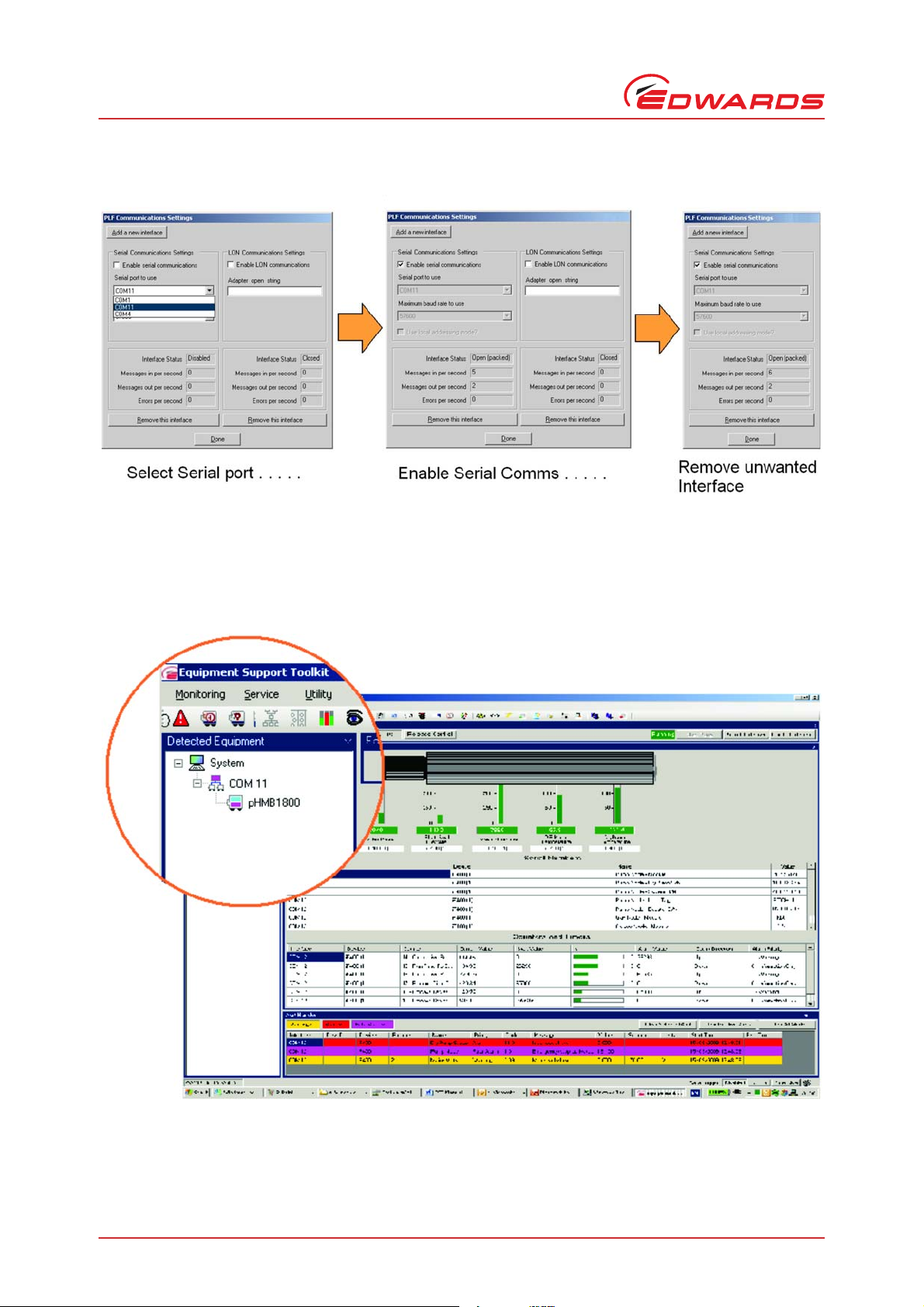
Figure 7 - Serial communication settings
Follow the above steps to select desired serial port (note that actual port allocations may differ from the example
shown above).Successful Communications will be indicated by the interface status changing to 'open (packed)'.
Additionally, the 'Detected Equipment' window will show the identity of the connected equipment (see example
below).
Figure 8 - Detected equipment (serial)
Page 8 © Edwards Limited 2017. All rights reserved.
Edwards and the Edwards logo are trademarks of Edwards Limited.
Page 15
D372-17-880 Issue C
If the pump is iGX, iXH, iXL, iXM, GXS or CXS, then Ethernet communications can be used to talk to the pump. This
is the fastest communications protocol for these pump types and is therefore recommended. To select Ethernet
communications with a pump, choose PLF over TCP/IP as the PLF communications settings.
If the pump isn't already connected to an Ethernet network, plug a cable directly from the pump to the Ethernet
socket on your PC. If it is on a network, connect your PC to the switch nearest the pump with an Ethernet cable.
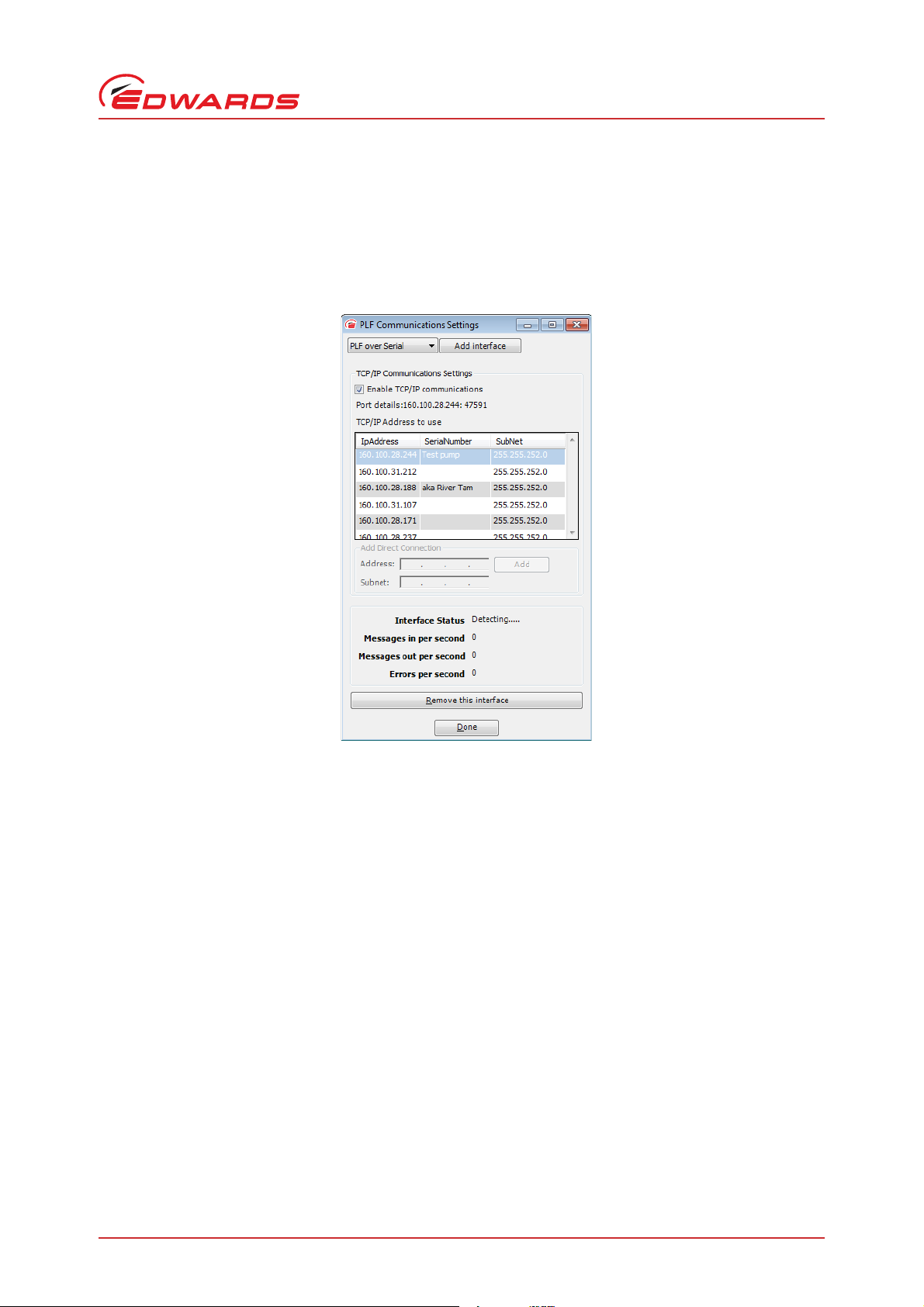
Figure 9 - Adding Ethernet PLF communications
Installation
To find the IP address of your pump, connect a PDT and look under Setup->IP Config->IP address.
This IP address should be listed as one of the addresses in the table TC/IP Addresses to use. Select it and then press
'Done' to enable communications. Alternatively, you can identify the pump using its serial number and then press
'Done'.
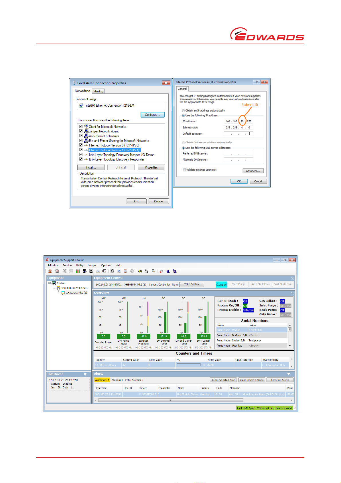
If the pump is not in the list of IP addresses, then the PC's net mask or IP address domain might not be set correctly.
In that case, go to the Windows Control Panel/Network and Sharing Center and select the ethernet connection to be
used. Edit the Local Area Connection properties by pressing the LAN settings button, selecting Internet Protocol
Version 4 (TCP/IPv4) from the list and press 'Properties'. Enter a compatible IP address to make the pump visible (one
with the same Subnet ID. If both your PC and the pump are already on the same network, then you shouldn't need to
do this.
© Edwards Limited 2017. All rights reserved.© Edwards Limited 2017. All rights reserved. Page 9
Edwards and the Edwards logo are trademarks of Edwards Limited.
Page 16
D372-17-880 Issue C
Installation
Figure 10 - Setting the IP address on a Windows PC
Once you have Ethernet communications with the pump, then the pump will be listed with its IP address in the left
hand side 'Equipment' box in the EST window.
Figure 11 - Equipment list in EST window
Page 10 © Edwards Limited 2017. All rights reserved.
Edwards and the Edwards logo are trademarks of Edwards Limited.
Page 17
D372-17-880 Issue C
3 Equipment support toolkit - main
features
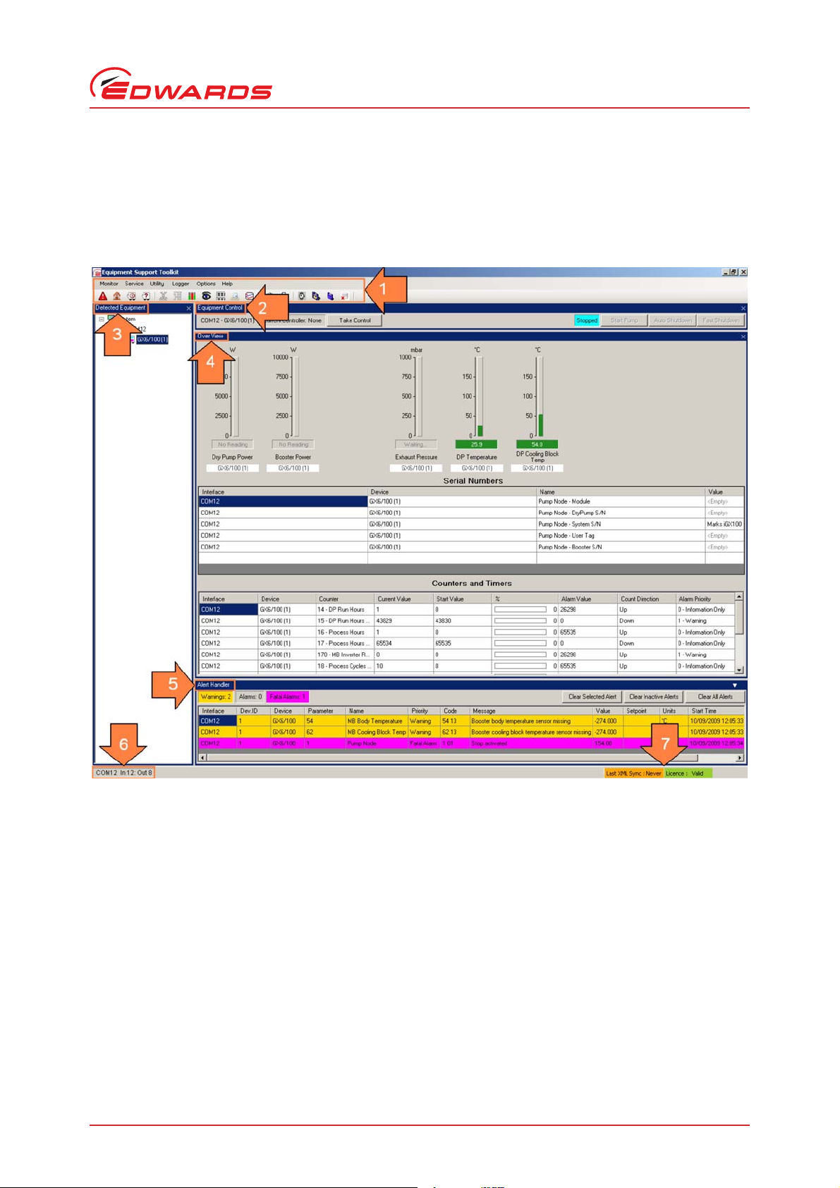
Figure 12 - Typical EST main view (iGX pump connected)
Equipment support toolkit - main features
Key to EST Main View:
1. Main Menu and navigation icons - provides access to Monitoring menu, Service menu, Utility menu, Logger menu,
options and Help. Each menu will be covered in more detail in later sections.
© Edwards Limited 2017. All rights reserved.© Edwards Limited 2017. All rights reserved. Page 11
Edwards and the Edwards logo are trademarks of Edwards Limited.
Page 18
D372-17-880 Issue C
Equipment support toolkit - main features
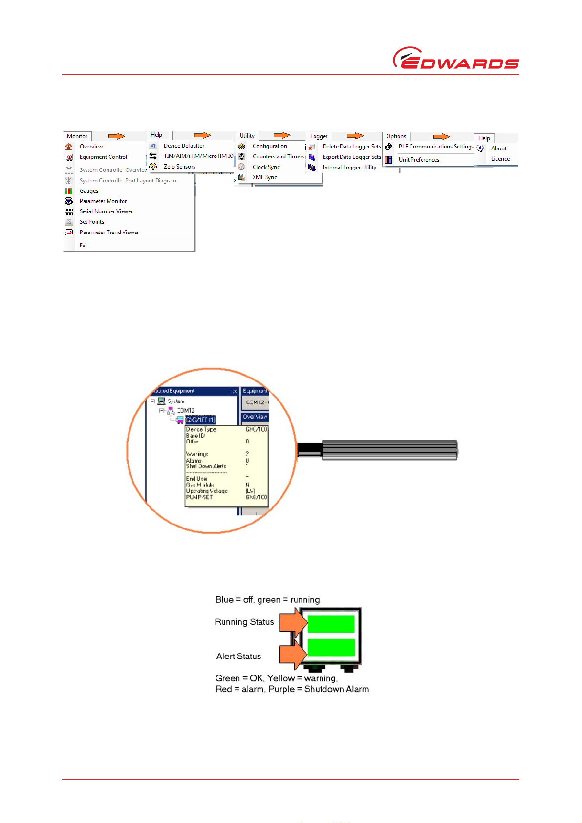
Figure 13 - EST menus
2. Equipment Control - enables the pump to be started and stopped and provides feedback of pump status. The
user can also take control from another control source such as a pump display terminal (PDT).
3. Detected Equipment. The currently connected equipment is shown here. Placing your mouse pointer directly
over the equipment name will display a pop-up window showing details of the connected device.
Figure 14 - Device information pop-up window
The equipment icon gives an instant indication of the running status and the alert status. When connected to
equipment hosting multiple devices, a separate icon will be shown for each device.
Figure 15 - Detected equipment icon
Page 12 © Edwards Limited 2017. All rights reserved.
Edwards and the Edwards logo are trademarks of Edwards Limited.
Page 19

D372-17-880 Issue C
Figure 16 - Detected equipment, system controller example
4. Main window. The example in figure 19 shows the default Overview page. Different pages (or tools) can be
chosen from the icons or from the menu system. The various tools available will be described in later sections of
this manual.
5. Alert handler - lists alerts as they occur and provides a simple alert administration facility. The user can clear
individual alerts, all alerts or all inactive alerts. Clearing active alerts will result in the alerts re-appearing in the
alert handler as they are broadcast from the connected equipment. The Alert Handler is covered in more detail
in a later section.
Equipment support toolkit - main features
6. Communications Activity Window - shows message activity between EST and connected equipment.
7. Indicators to show when last XML synchronisation occurred and status of EST Licence. The XML files contain
equipment-specific messages that are used by EST.
© Edwards Limited 2017. All rights reserved.© Edwards Limited 2017. All rights reserved. Page 13
Edwards and the Edwards logo are trademarks of Edwards Limited.
Page 20

D372-17-880 Issue C
This page has been intentionally left blank.
Page 14 © Edwards Limited 2017. All rights reserved.
Edwards and the Edwards logo are trademarks of Edwards Limited.
Page 21
D372-17-880 Issue C
4 Using the monitoring tools
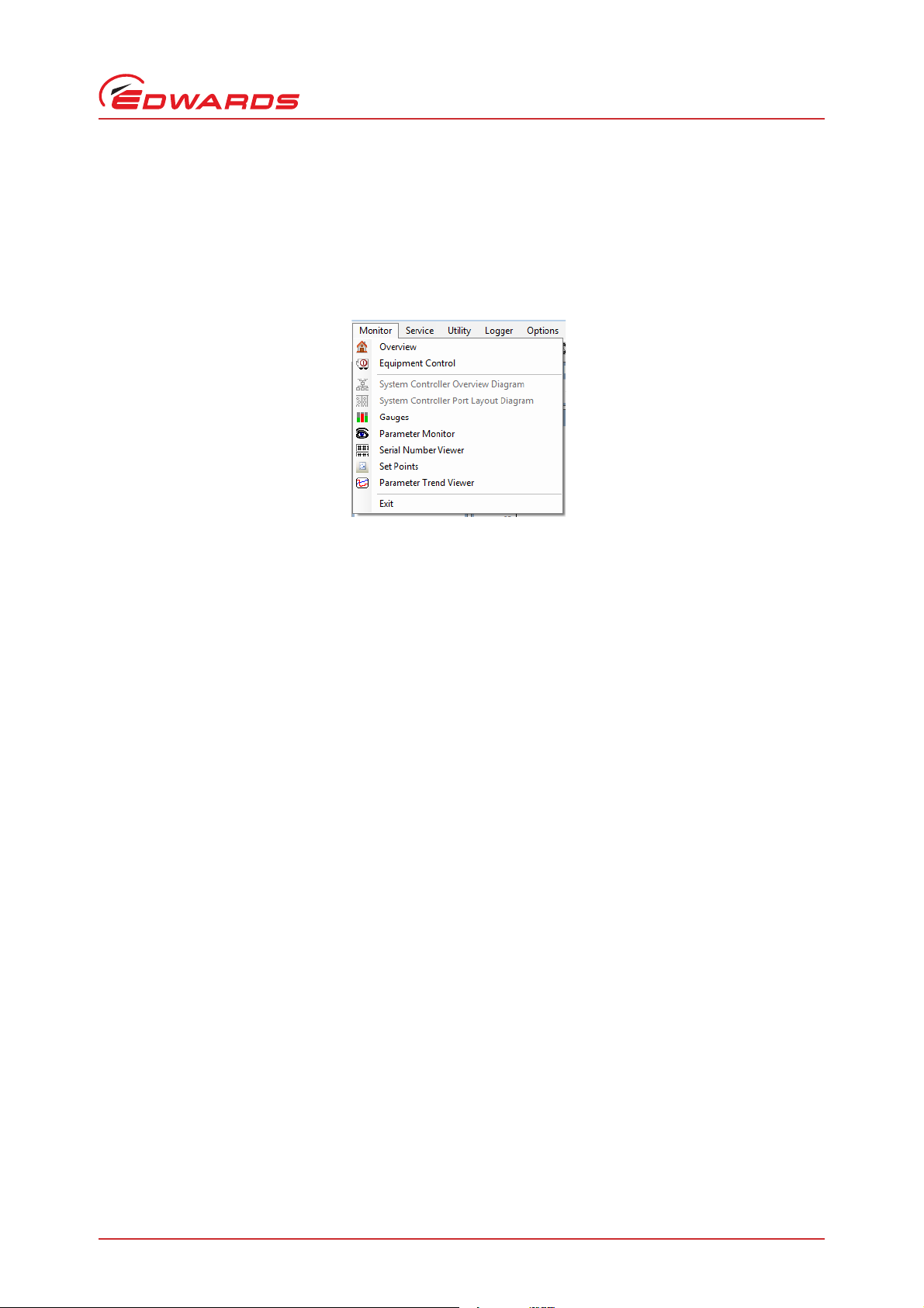
EST provides a comprehensive set of tools to monitor connected equipment. The tools can be accessed via the
Monitoring menu shown below:
Figure 17 - The monitoring menu
The monitoring menu is split into two sections:
Using the monitoring tools
The top section contains the 'default' tools that normally occupy the application - these tools are enabled
and shown at their maximum size when the application is first opened
The lower section of the monitoring menu lists a selection of single-task monitoring tools that enable the
user to monitor equipment data in more detail
The following sections explain how to use each tool.
© Edwards Limited 2017. All rights reserved.© Edwards Limited 2017. All rights reserved. Page 15
Edwards and the Edwards logo are trademarks of Edwards Limited.
Page 22

D372-17-880 Issue C
Using the monitoring tools
4.1 Overview
Figure 18 - Example overview
The Overview screen provides key information from the connected equipment in a single view comprising the
following:
Gauge pane - up to 6 gauges showing key parameters
Input/output status pane showing key I/O states
Serial Numbers list (scrollable) showing all available numbers
Counters /Timers list (scrollable) showing all available stored data
Each pane listed above can be selected as an individual tool from the main monitoring menu.
4.2 Equipment detection
The Equipment Detection tool provides the following functionality:
Automatic detection and display of all equipment types that are connected.
Hierarchical view shows all communication ports in use.
Attached equipment displayed as a tree view.
'Active' equipment icons showing colour-coded running and alarm status.
Display of offset addresses for equipment attached to System Controllers.
The Equipment Detection tool can be closed and re-opened using the dedicated icon .
For further information on using the Equipment Detection tool, please refer to Section 3.
Page 16 © Edwards Limited 2017. All rights reserved.
Edwards and the Edwards logo are trademarks of Edwards Limited.
Page 23

D372-17-880 Issue C
4.3 The Alert Handler
The Alert Handler is a core service. It is always operational and visible whilst equipment is connected.
The basic functionality of the Alert Handler has already been covered in Section 3.
Three types of alert are handled:
Warnings (yellow) - a parameter has exceeded a high or low warning threshold, but equipment will continue
to run.
Alarms (red) - a parameter has exceeded a high or low alarm threshold. Equipment will shut down (unless the
equipment associated with the alert has been configured for 'Run Til Crash' operation).
Fatal Alarms (purple) - these are alarms that override ‘Run Til Crash’ mode and shut the equipment down.
E.g. an exhaust overpressure alarm on parameter 39.
Clicking on the Alert Handler icon or the Alert Handler option from the Monitoring menu alternately minimises
and maximises the Alert Handler as shown below:
Figure 19 - Alert Handler (maximised)
Using the monitoring tools
Figure 20 - Alert Handler (minimised)
An alert message contains the following information:
Figure 21 - Alert message information
Key to Figure 19:
1. Alert Source (Communication port that equipment is connected to).
2. Equipment base ID (typically 1 for drypumps, 801 for boosters). For equipment connected via a system
controller, numbers will be offset by 1000 for each device e.g. 2001, 3001 etc.
3. Equipment type to which it applies.
4. Equipment Parameter (parameter numbers andand names tend to be common across all equipment types).
5. Parameter Name.
6. Alert priority type (Warning/ Alarm/ Fatal Alarm).
© Edwards Limited 2017. All rights reserved.© Edwards Limited 2017. All rights reserved. Page 17
Edwards and the Edwards logo are trademarks of Edwards Limited.
Page 24

D372-17-880 Issue C
Using the monitoring tools
7. Alert code (this should always be quoted in any correspondence with Edwards).
8. Alert message.
9. Current parameter value.
10. Setpoint that was exceeded.
11. Applicable units.
12. Time and date at which alert first occurred.
If a parameter should return to its normal operational range after going into an alert state, the alert message will be
clearly identified as over. Any inactive alerts can be cleared using the 'Clear Inactive Alerts button.
Figure 22 - Alert over (coloured text on white background and end time shown)
4.4 Equipment Control
Equipment Control is an optional service in that the tool can be closed when not needed. The Equipment Control bar
can be reinstated by clicking on the Equipment Control icon or by selecting Equipment Control from the
Monitoring menu.
The Equipment Control bar enables the user to take control of currently selected equipment and once under control
of the PC, to start up and shut down that equipment.
Figure 23 - Equipment control
Key to Figure 21
1. Communication port allocated to selected equipment.
2. Current Control Source (Pump Display Terminal, Tool Interface or PC).
3. Take Control/Release Control button.
4. Pump Status Indicator (Stopped/Starting/Running/Stopping).
5. Start Equipment.
6. Auto Shutdown (initiates a managed shutdown).
7. Fast Shutdown (Equipment is shut down safely as rapidly as possible).
4.5 Viewing parameters using the gauge tool
The gauges tool allows a user to select and view analogue parameters in a vertical bar gauge format. The tool can
be selected directly using the Gauge tool icon or via the monitoring menu. A typical gauge view is shown in
Figure 24:
Page 18 © Edwards Limited 2017. All rights reserved.
Edwards and the Edwards logo are trademarks of Edwards Limited.
Page 25

Key to Figure 22
D372-17-880 Issue C
Using the monitoring tools
Figure 24 - Typical gauge pane view (iF400 default selection)
1. A gauge typically provides the following information:
Parameter value (shown in bar and numerical format)
Name of parameter
Alert limits on side bar (warning, alarm and shutdown alarm)
Units of measurement and scale
Equipment to which the parameter belongs
2. A pop-up tool tip style window displays key parameter data when the mouse pointer is placed over the
equipment name underneath the chosen parameter.
3. The Select Parameters button enables the user to choose other parameters for display. A new tabbed display
panel is created when the number of selected parameters can no longer fit on one panel.
Referring to Figure 25, each analogue parameter is assigned an importance level (high, medium or low). The default
view for each equipment family displays gauges for 'high' importance parameters only. The window above can be used
to customise the gauges tool to the requirements of the user. The settings are retained whilst the equipment is
connected. Disconnecting the equipment or closing and re-opening the application will reset the gauges tool to the
default settings.
© Edwards Limited 2017. All rights reserved.© Edwards Limited 2017. All rights reserved. Page 19
Edwards and the Edwards logo are trademarks of Edwards Limited.
Page 26

D372-17-880 Issue C
Using the monitoring tools
Figure 25 - Gauges - select parameters
4.6 Parameter message monitoring
The parameter message monitor provides a useful method of monitoring messages as they are broadcast from the
attached equipment. The parameter message monitor can be directly selected using the icon or via the
monitoring menu. An example parameter message monitor screen is shown below:
Figure 26 - Parameter message monitor
When the tool is first selected, the most frequently broadcast parameters will populate the grid first. Over a short
period of time, parameters that broadcast less frequently will be captured until at least one instance of each
parameter has been recorded. The grid will continually be updated as new values are received by EST. The update
rates vary between 1 second for high-importance parameters such as power and current to 45 seconds for some of
the less important parameters.
Page 20 © Edwards Limited 2017. All rights reserved.
Edwards and the Edwards logo are trademarks of Edwards Limited.
Page 27

D372-17-880 Issue C
4.7 Reading system serial numbers
To read serial numbers from attached equipment, a dedicated tool is provided. An example screen is shown below.
Figure 27 - Serial number viewer
Using the monitoring tools
The example above shows an iF400 Drypump/Booster combination with a single board controller.
Gas node module and Sensor node module numbers are only available from iQ pumps and early iH pumps with
distributed control systems.
Display node, NIM node and TIM node will be shown if the devices are present.
The tool will not permit numbers to be edited.
© Edwards Limited 2017. All rights reserved.© Edwards Limited 2017. All rights reserved. Page 21
Edwards and the Edwards logo are trademarks of Edwards Limited.
Page 28

D372-17-880 Issue C
Using the monitoring tools
4.8 Viewing alert setpoints
The Setpoints Viewer provides the user with a detailed view of the setpoints for all the key parameters of the
attached equipment. The viewer also displays the real time values of each parameter. The tool can be selected
directly using the icon or via the monitoring menu.
For a typical parameter, there may be up to 4 individual setpoints as follows:
When first opened, the Setpoint Viewer will show the setpoints for the high importance parameters belonging to the
attached equipment. The example below is for an iF400:
Figure 28 - Setpoint viewer
Key to Figure 26
1LoSetpt2
2LoSetpt1 Low warning - i.e. low coolant temperature
3HiSetpt1
4HiSetpt2 High Alarm/shutdown alarm - i.e. very high coolant temperature
5 Select Parameters - allows user to customise parameter list
The parameter selection window is identical in functionality to that employed by the Gauges tool (please refer to
Section 4.5).
Low alarm/shutdown alarm - i.e. very low coolant temperature
High warning - i.e. high coolant temperature
4.9 Using the Parameter Trend Viewer (live data graphing)
The Parameter Trend Viewer provides the user with a configurable real-time graphing tool that can plot up to 6
parameters simultaneously. The tool can be selected directly using the icon or via the monitoring menu.
Upon selecting the tool for the first time, the user is presented with a list of parameters from which a maximum of
any six can be chosen. Make your choice by selecting required parameters and click on the OK button when done.
Page 22 © Edwards Limited 2017. All rights reserved.
Edwards and the Edwards logo are trademarks of Edwards Limited.
Page 29

D372-17-880 Issue C
Using the monitoring tools
A typical trend view is shown below
Key to Figure 27
Figure 29 - Parameter trend view
1. Select Parameters. Click here to select new parameters for display. The trending tool can display up to six
parameters simultaneously. The parameter selection page functions in a similar way to the example already
described for the gauge tool (please refer to Section 4.5).
2. Show limits. Any applicable setpoint limits for the currently displayed parameters can be chosen from this drop
down list. This example shows the applied limits for exhaust pressure.
Figure 30 - Select setpoint limits
3. Apply time period - the X-axis can be set for a period between 1 minute and 99 days.
© Edwards Limited 2017. All rights reserved.© Edwards Limited 2017. All rights reserved. Page 23
Edwards and the Edwards logo are trademarks of Edwards Limited.
Page 30

D372-17-880 Issue C
This page has been intentionally left blank.
Page 24 © Edwards Limited 2017. All rights reserved.
Edwards and the Edwards logo are trademarks of Edwards Limited.
Page 31

D372-17-880 Issue C
CAUTION
5 The Configuration Handler
The Configuration Handler provides a selection of tools to allow the user to acquire, apply and manage configuration
data. To ensure ease of use, the layout of the utility is similar to that employed by Microsoft™ for Windows Explorer.
Edwards semiconductor pumping equipment can be re-configured to meet specific user requirements. The reconfiguration may take the form of a modified parameter setpoint or setting an accessory-related parameter to
fitted. To modify equipment, a configuration data file (hereinafter referred to as a 'Configuration Set') containing
the revised data must be applied via the serial port.
Where Edwards equipment connects to the customer tool via a Tool Interface Module (TIM), EST provides a tool for
applying Configuration Sets to a TIM Recipe Handler. The Recipe Handler in the TIM automatically applies any stored
sets to connected equipment as it is powered on thereby ensuring that a replacement pump is configured correctly
for use with the host tool.
The Configuration Handler can also be used to acquire configuration data from attached equipment. Acquired data
can be saved into sets that can be used for comparison with other acquired sets for verification purposes. Acquired
sets can also be exported for use on other EST-equipped PCs.
Only use Edwards approved 'D' numbered Configuration Sets. If in doubt, contact your local Edwards
representative. Do not attempt to modify exported configuration sets.
The Configuration Handler
5.1 Selecting the Configuration Handler
The Configuration Handler can be se l ected di r e ctly usi n g the Con f i guratio n H andler i c o n or via t h e Utiliti e s menu.
Figure 31 - Selecting the Configuration Handler
5.2 Configuration Handler toolset
The Configuration Handler is provided with a toolbar for navigation purposes. Some tools can be accessed by selecting
and right-clicking on a chosen configuration set and then selecting the required function from the drop-down list.
The following sections explain each tool in detail
Figure 32 - EST Configuration Handler toolbar
© Edwards Limited 2017. All rights reserved.© Edwards Limited 2017. All rights reserved. Page 25
Edwards and the Edwards logo are trademarks of Edwards Limited.
Page 32

D372-17-880 Issue C
The Configuration Handler
Figure 33 - EST Configuration Handler, tool selection drop down list
5.3 Configuration Handler - creating a new folder
The procedure for creating a new folder is initiated by clicking on the 'New Folder' icon . Upon selecting the
icon, a new folder is automatically created with the name 'New Folder'. The new folder is automatically highlighted
to allow a new name to be entered.
Figure 34 - Creating a new folder
5.4 Configuration Handler - viewing a configuration set
There are three ways in which a Configuration Set can be opened for viewing:
Select (highlight) the required set and click on the 'View Set' icon
Right-click on the required set and choose the view set icon from the drop-down list
Double-click on the required set
Page 26 © Edwards Limited 2017. All rights reserved.
Edwards and the Edwards logo are trademarks of Edwards Limited.
Page 33

An example of a set opened for viewing is shown below:
Figure 35 - Viewing a set
D372-17-880 Issue C
The Configuration Handler
Key to Figure 35
1. A list of named configuration items is shown on the left - hand side of the viewing window. For each named item,
a parameter ID and a Configuration ID is quoted. For a given parameter ID there can be multiple configuration
items. For example a Parameter ID such as Dry Pump Power (Parameter 4) could have Configuration 86 (alert
filtering) and Configuration 0 (Analogue setpoint values) included in the same set.
2. The list on the right-hand side of the viewing window shows the fields that comprise a configuration item. The
example shown above is Configuration ID zero, (analogue setpoint values) for parameter 54 (booster body
temperature). The example shows that a configuration 'item' can comprise multiple value fields. The fields are
not editable.
The viewing window can be closed by clicking on the 'OK' or 'Cancel' buttons.
5.5 Configuration Handler - renaming a set
A Configuration Set can be renamed in two ways:
1. Highlight the set and click on the 'Rename Set' toolbar button. The set will then be selected for renaming
and the new name can be keyed in followed by the 'Enter' key to complete the operation.
2. Right-click on the chosen set. A drop down list including the 'Rename' option will be displayed. Key in the new
name followed by the 'Enter' key.
The renaming procedure can be aborted by pressing the 'Escape' key. The set name will revert to the original name.
© Edwards Limited 2017. All rights reserved.© Edwards Limited 2017. All rights reserved. Page 27
Edwards and the Edwards logo are trademarks of Edwards Limited.
Page 34

D372-17-880 Issue C
The Configuration Handler
5.6 Configuration Handler - deleting a set
A Configuration Set can be deleted in two ways:
1. Highlight the set and click on the 'Delete Set' toolbar button. The user will be asked to confirm or cancel
the delete operation.
2. Right-click on the chosen set. A drop down list including the 'Delete' option will be displayed. Choose the delete
option and confirm or cancel the delete procedure when asked.
Multiple sets can be deleted by selecting sets using the up/down arrows whilst holding down the shift key. The delete
procedure will then handle the sets as a group for deletion purposes.
5.7 Configuration Handler - duplicating a set
A Configuration Set can be duplicated in two ways:
1. Highlight the set and click on the 'Duplicate Set' toolbar button. A copy will be created with the prefix
'Copy of' followed by the existing file name. For example, if a set named iH Gate Valve Enable was duplicated,
the new file would be named 'Copy of iH Gate Valve Enable'.
2. Right-click on the chosen set. A drop down list including the 'Duplicate' option will be displayed. Upon choosing
the option, the procedure is identical to that already described.
When a duplicate set is first created, it is appended to the end of the currently selected folder. The Configuration
Sets are re-sorted alphabetically only when the Configuration Handler is closed and then re-opened.
5.8 Configuration Handler - comparing a set
The 'Compare Set' tool is useful for such tasks as comparing a 'D' numbered Configuration Set with a set acquired from
a pump. The compare tool will highlight the configuration items that are identical and those which differ. In addition,
the tool will also identify items that appear in one set only.
The Compare Set tool employs a simple 'Wizard' procedure with on-screen instructions at every stage.
To begin the Compare Sets procedure, select the 'Compare Sets' icon on the Configuration Handler toolbar.
Figure 36 - Compare Sets, compare sets for comparison
The above screen prompts the user to select at least two sets for comparison (note that the tool will permit more
than two sets to be compared if required).
Select the required sets and press 'Next'.
Page 28 © Edwards Limited 2017. All rights reserved.
Edwards and the Edwards logo are trademarks of Edwards Limited.
Page 35

D372-17-880 Issue C
5.9 Configuration Handler - importing a set
The Import tool enables the user to import configuration sets from the following equipment support packages: Single
Equipment Monitor (SEM), FabWorks 1.XX and FabWorks 2.XX. Upon importing a set, the internal structure of the set
is automatically converted to the EST standard. Sets that do not conform to one of the above three standards will be
rejected by the Import tool.
The Import tool employs a simple 'Wizard' procedure with on-screen instructions at every stage.
To import a file, select the Import icon from the Configuration Handler toolbar. From the first screen of the
import wizard, select the browse button at the right hand end of the source folder path.
Figure 37 - Importing a Configuration Set, select source folder
The Configuration Handler
Navigate to and select the source folder that contains the configuration set to be imported…
Figure 38 - Importing a Configuration Set, source folder selected
© Edwards Limited 2017. All rights reserved.© Edwards Limited 2017. All rights reserved. Page 29
Edwards and the Edwards logo are trademarks of Edwards Limited.
Page 36

D372-17-880 Issue C
The Configuration Handler
Select ‘Next’ to list the Configuration Sets in the chosen folder.
Figure 39 - Importing a Configuration Set, select set for import
Select ‘Next’ and then ‘yes’ when requested to proceed with the import process.
Figure 40 - Importing a Configuration Set, confirm import
After selecting ‘Yes’, the import will be executed. A report will be posted in the results window to confirm that the
import process was successful (See Figure 41).
Page 30 © Edwards Limited 2017. All rights reserved.
Edwards and the Edwards logo are trademarks of Edwards Limited.
Page 37

Click on 'Finish' when done.
D372-17-880 Issue C
The Configuration Handler
Figure 41 - Importing a Configuration Set, import successful
The imported set is now in the correct format for EST and can be safely applied to a matching equipment type.
5.10 Configuration Handler - acquiring configuration data
The Acquire tool enables the user to acquire configuration data from attached equipment and save it to a
Configuration Set. The acquire procedure requires the user to supply a name for the new set. The acquire procedure
is particularly useful for tasks such as verifying the configuration settings within equipment by comparing an acquired
set against a known good set.
TIM Recipe Handlers:
If the attached equipment is being used with a TIM, iTIM or MicroTIM, the Acquire tool also provides the option to
acquire any stored Configuration items in the TIM recipe handler. Configuration items stored in the Recipe Handler
are automatically transferred to connected equipment on power-up. This ensures that swapped-out equipment is
always correctly configured for it's intended use. The TIM Recipe Handler groups configuration items by equipment
family (iQ, iH etc).
5.10.1 Acquiring data from equipment
To acquire configuration data from attached equipment, proceed as follows:
Select the Acquire icon from the Configuration Handler toolbar.
© Edwards Limited 2017. All rights reserved.© Edwards Limited 2017. All rights reserved. Page 31
Edwards and the Edwards logo are trademarks of Edwards Limited.
Page 38

D372-17-880 Issue C
The Configuration Handler
Figure 42 - Select acquired data source (equipment)
Choose the option to 'Acquire from System and select 'Next'.
Page 32 © Edwards Limited 2017. All rights reserved.
Edwards and the Edwards logo are trademarks of Edwards Limited.
Page 39

Figure 43 - Choose configuration items
D372-17-880 Issue C
The Configuration Handler
The configuration item selection window provides options to acquire all the configuration items or all the nonoptional items. To choose individual items, select 'none' and then select the required items from the list. (see below)
Figure 44 - Individual configuration items selected
For pump types that support the feature, the box 'Changed Only' appears. Ticking this box restricts the list of
configuration items selectable to those that have been changed to be different from their default settings.
Click on ‘Next’ when configuration items have been chosen.
© Edwards Limited 2017. All rights reserved.© Edwards Limited 2017. All rights reserved. Page 33
Edwards and the Edwards logo are trademarks of Edwards Limited.
Page 40

D372-17-880 Issue C
The Configuration Handler
Figure 45 - Acquired data report
The Acquired Data Report lists all the successfully acquired items.
The contents of a configuration item can be viewed by clicking on the item in the grid. The data fields for the item
will be displayed on the right-hand side of the grid.
Select 'Next' when done.
Figure 46 - Naming an acquired set
Name the new Configuration Set and select OK. The procedure for acquiring data from attached equipment is now
complete.
Page 34 © Edwards Limited 2017. All rights reserved.
Edwards and the Edwards logo are trademarks of Edwards Limited.
Page 41

D372-17-880 Issue C
5.10.2 Acquiring data from a TIM Recipe Handler
To acquire data from a TIM Recipe Handler, proceed as follows:
Select the Acquire icon from the Configuration Handler toolbar.
If a TIM/iTIM or MicroTIM is detected, the options of acquiring data from the system or from the TIM/iTIM/MicroTIM
Recipe Handler will be offered.
Figure 47 - Select acquired data source (Recipe Handler)
The Configuration Handler
Choose ‘Acquire From Recipe Handler’ and select ‘Next’
Figure 48 - Acquire data from TIM, choose equipment type
© Edwards Limited 2017. All rights reserved.© Edwards Limited 2017. All rights reserved. Page 35
Edwards and the Edwards logo are trademarks of Edwards Limited.
Page 42

D372-17-880 Issue C
WARNING
The Configuration Handler
The Recipe Handler lists the contents by equipment type (note that GX/iGX/iXH/iXL/iXM/GXS/pHMB and variants are
all grouped under type:other). Select the type of equipment for which you wish to extract the configuration items
and select 'Next'.
Figure 49 - Acquire data from TIM, choose items
The TIM Recipe Handler does not identify the stored items, it only provides information on the number of stored items
per equipment type. If you know the parameter number/configuration type for each stored item, select option 'None'
and then select each item you wish to acquire by clicking on the corresponding check box in the 'Get' column. If you
are unsure of the parameter number/configuration type identities, use the default option 'All'. This option does take
longer to execute but will ensure that all configuration items held in the TIM for your chosen equipment type will be
acquired.
Click on 'Next' when done.
The remaining steps to acquire the data and store as a Configuration Set follow the procedure explained in the
previous section.
5.11 Configuration Handler - applying configuration data
Using this facility can change the way in which equipment operates. The facility should only be
used to apply Edwards approved sets.
The Apply tool allows a user to perform the following procedures:
Apply a Configuration Set to attached equipment
Page 36 © Edwards Limited 2017. All rights reserved.
Edwards and the Edwards logo are trademarks of Edwards Limited.
Page 43

Apply a Configuration Set to the TIM Recipe Handler of attached equipment
Apply a Configuration Set to the Recipe Handler of a System Controller
5.11.1 Applying a Configuration Set
To apply a set to connected equipment, select a set as shown below.
Figure 50 - Apply Set to equipment, selecting a set
D372-17-880 Issue C
The Configuration Handler
Click on the Apply Set icon
(The chosen set must be compatible with the attached equipment type)
© Edwards Limited 2017. All rights reserved.© Edwards Limited 2017. All rights reserved. Page 37
Edwards and the Edwards logo are trademarks of Edwards Limited.
Page 44

D372-17-880 Issue C
The Configuration Handler
Figure 51 - Apply Set, select equipment (system) as destination
If the attached equipment is hosting a TIM, iTIM or MicroTIM, the option to apply the selected set to the system or
the TIM Recipe Handler will be offered. To apply the set directly to the attached equipment, select 'Apply to System'
followed by the 'Next' key.
Figure 52 - Apply Set, check offset
The offset addresses of the equipment and the set to be applied are displayed here. If there is a difference in
addresses, the offset address of the set will be automatically adjusted to match that of the attached equipment when
the set is applied.
Select 'Next' to continue.
Page 38 © Edwards Limited 2017. All rights reserved.
Edwards and the Edwards logo are trademarks of Edwards Limited.
Page 45

Figure 53 - Apply Set, display contents
D372-17-880 Issue C
The Configuration Handler
The above screen allows the user to check the contents of a set before it is applied to the attached equipment.
Select 'Next' to proceed.
Figure 54 - Apply Set to equipment
The above screen provides a report on each applied configuration item. Select 'Close' to continue if all results are OK.
The procedure for applying a set to single equipment is now complete.
© Edwards Limited 2017. All rights reserved.© Edwards Limited 2017. All rights reserved. Page 39
Edwards and the Edwards logo are trademarks of Edwards Limited.
Page 46

D372-17-880 Issue C
The Configuration Handler
5.11.2 Applying Sets to a TIM Recipe Handler
The various types of Tool Interface Module (TIM, iTIM, MicroTIM) all provide a Recipe Handler that can store
configuration data for the hosted pump. Configuration data stored in a TIM Recipe Handler will be transferred to the
hosted pump at a 'power on' event this ensures that exchanged pumps are always configured for the intended process
task.
As a general rule, TIM and iTIMs tend to be used with iQ and iH/iL/iF equipment types.
MicroTIMs plug directly into the host equipment and are used by GX/iGX/iX series pump types.
To apply a configuration set to a TIM Recipe Handler, proceed as follows:
Select 'Apply Set and select 'Apply to Recipe Handler'.
Figure 55 - Select TIM Recipe Handler
Select ‘Next’ to advance to Recipe Handler contents view.
The TIM/iTIM can store configuration items for multiple equipment types in dedicated 'slot' positions. An example is
shown below.
Page 40 © Edwards Limited 2017. All rights reserved.
Edwards and the Edwards logo are trademarks of Edwards Limited.
Page 47

Figure 56 - View TIM Recipe Handler contents (TIM/iTIM only)
D372-17-880 Issue C
The Configuration Handler
The MicroTIM (microTIM) only stores configuration items for a single equipment type (the action of plugging a
microTIM into a different generation of equipment will erase any stored configuration items).
A typical example view of the Recipe Handler contents for a microTIM installed on an iXH-type pump is shown below:
© Edwards Limited 2017. All rights reserved.© Edwards Limited 2017. All rights reserved. Page 41
Edwards and the Edwards logo are trademarks of Edwards Limited.
Page 48

D372-17-880 Issue C
The Configuration Handler
Figure 57 - View MicroTIM Recipe Handler contents
For all types of TIM, the number of stored items of the same equipment type as the set to be applied is displayed
here. If the set contains duplicate items, these will over-write the items already stored in the TIM. If OK, press 'Next'
to continue.
The remaining steps to apply the set are explained in the earlier section covering the application of a set to Single
Equipment.
Page 42 © Edwards Limited 2017. All rights reserved.
Edwards and the Edwards logo are trademarks of Edwards Limited.
Page 49

D372-17-880 Issue C
5.11.3 Sending a set to USB device
If your pump has a USB socket, it is possible to use USB memory drive to apply configuration sets to a pump.
Configuration sets to be applied to a pump via a USB memory device must be loaded onto the memory device by
selecting the configuration to be loaded and then clicking to show the "Send to USB" option.
Figure 58 - Send Configuration to USB
The Configuration Handler
5.12 Configuration Handler - Recipe Handler Utilities
The Recipe Handler Utility provides the following information/functionality:
Information - Number of items currently stored
Information - Remaining available space
Functionality - Delete Recipe from handler
Functionality - Transfer Recipe from Recipe Handler to the hosted equipment
© Edwards Limited 2017. All rights reserved.© Edwards Limited 2017. All rights reserved. Page 43
Edwards and the Edwards logo are trademarks of Edwards Limited.
Page 50

D372-17-880 Issue C
The Configuration Handler
Figure 59 - MicroTIM and TIM/iTIM Recipe Handler Utility, example views
MicroTIM Recipe Handler typical view TIM/iTIM Recipe Handler typical view
For the TIM and iTIM, recipes can be deleted for individual equipment types.
Page 44 © Edwards Limited 2017. All rights reserved.
Edwards and the Edwards logo are trademarks of Edwards Limited.
Page 51

D372-17-880 Issue C
6 The Data Logger
The Data Logger menu provides a collection of utilities that enable the user to carry out the following tasks:
Retrieve internally logged data from attached equipment
Export log file to Tab Separated Variable (TSV) format
Delete unwanted log files from the EST database
6.1 Retrieving data using the Internal Logger Utility
The Internal Logger enables the user to retrieve internally logged data from attached equipment. The data set is
stored to the EST database and is uniquely referenced by a user-specified name and description. The data can be
retrieved as follows:
Go to the data logger menu and select 'Internal Logger Utility' or select the internal logger icon from the main
toolbar.
From the following screen, select 'Next'.
Figure 60 - Internal Logger Utility start screen
The Data Logger
Enter Log file (data set) name (1) and description (2) and select ‘Next’.
Figure 61 - Internal Logger Utility, enter log file name and description
© Edwards Limited 2017. All rights reserved.© Edwards Limited 2017. All rights reserved. Page 45
Edwards and the Edwards logo are trademarks of Edwards Limited.
Page 52

D372-17-880 Issue C
The Data Logger
Figure 62 - Internal Logger Utility, select internal log
Figure 63 - Internal Logger Utility, acquiring internal logs
When the internal logs have been acquired, press ‘Next’ to continue.
Page 46 © Edwards Limited 2017. All rights reserved.
Edwards and the Edwards logo are trademarks of Edwards Limited.
Page 53

D372-17-880 Issue C
When connected to a pump type supporting expanded logging, the following screen will be displayed to select which
data to select the data type and time range of log data to acquire.
Figure 64 - Internal Logger Utility acquiring expanded internal log data
The Data Logger
There are three kinds of data log stored:
the 'standard data' log (parameter data stored on a regular long-term basis)
the 'session' log (user event data, e.g.: when a PC running EST has connected to the pump)
up to four 'critical data' logs (data stored after critical pump events, e.g. pump alarms)
When selecting which log data to acquire, the first date and last date boxes can be edited to select the time range
of data required. This can considerably reduce the time taken to acquire the data log.
Also the number of entries acquired from the standard data log can be changed by clicking on the Total Required
box. It defaults to be the most recent 60,000 entries. However, by clicking on it the entire standard data log is
selected for acquisition instead. This can also considerably reduce the data log acquisition time.
6.2 Exporting Internal logged data using ‘Export Logged Data Sets’
The 'Export Logged Data Sets' utility enables saved data sets to be exported to a user-specified folder as a 'TSV' (Tab
Separated Variable) format file. The TSV format is compatible with spreadsheet packages such as Microsoft™ Excel.
To select the export tool, go to the data logger menu and select 'Export Logged Data Sets' or select the icon
from the main toolbar.
© Edwards Limited 2017. All rights reserved.© Edwards Limited 2017. All rights reserved. Page 47
Edwards and the Edwards logo are trademarks of Edwards Limited.
Page 54

D372-17-880 Issue C
The Data Logger
Select the set to be exported from the following screen:
Figure 65 - Selecting a logged data set for export
Figure 66 - Choose a name and location for the exported set
Page 48 © Edwards Limited 2017. All rights reserved.
Edwards and the Edwards logo are trademarks of Edwards Limited.
Page 55

D372-17-880 Issue C
6.3 Deleting Sets of logged data
The EST database has sufficient capacity for many thousands of datasets. However, the task of listing and selecting
a set for export can become tedious when large numbers of sets are stored. The 'Delete Data Logger Sets' tool allows
the user to delete sets that are no longer required.
To select the Delete tool, go to the data logger menu and select 'Delete Data Logger Sets' or select the icon
from the main toolbar.
The following figure shows the utility window for deleting sets. The user can choose to delete either single or multiple
sets. The selected set(s) will not be deleted until the 'Delete' button is selected.
Figure 67 - Deleting logged data
The Data Logger
© Edwards Limited 2017. All rights reserved.© Edwards Limited 2017. All rights reserved. Page 49
Edwards and the Edwards logo are trademarks of Edwards Limited.
Page 56

D372-17-880 Issue C
This page has been intentionally left blank.
Page 50 © Edwards Limited 2017. All rights reserved.
Edwards and the Edwards logo are trademarks of Edwards Limited.
Page 57

D372-17-880 Issue C
7 Selecting display unit preferences
EST provides a utility that enables the unit preferences for temperature, flow, pressure and power to be customised.
The utility can be found in the Options menu. The following figure shows the full range of units available to the user.
Figure 68 - Unit Preference Selection (default shown)
Selecting display unit preferences
© Edwards Limited 2017. All rights reserved.© Edwards Limited 2017. All rights reserved. Page 51
Edwards and the Edwards logo are trademarks of Edwards Limited.
Page 58

D372-17-880 Issue C
This page has been intentionally left blank.
Page 52 © Edwards Limited 2017. All rights reserved.
Edwards and the Edwards logo are trademarks of Edwards Limited.
Page 59

D372-17-880 Issue C
8 XML equipment data synchronisation
EST utilises an encrypted XML based file system to support the different types of Edwards pumping equipment. The
content of these files is occasionally updated to support new equipment features or even new equipment types.
EST provides a synchronisation utility that connects to an Edwards server via the internet. Upon establishing a
connection, all the XML support files are individually checked against the versions held on the server and then
updated if necessary. The procedure can take up to 20 minutes to complete.
To start the synchronisation process, go to the Utilities menu and select 'XML Sync' or select the icon from the
main toolbar.
The following figure illustrates the connection between the PC receiving the updated files and the server. Press 'Next'
to continue.
Figure 69 - XML synchronisation start screen
XML equipment data synchronisation
The next screen provides confirmation of a connection to the internet. Press 'Next' when an internet connection is
established.
Figure 70 - Establish internet connection
© Edwards Limited 2017. All rights reserved.© Edwards Limited 2017. All rights reserved. Page 53
Edwards and the Edwards logo are trademarks of Edwards Limited.
Page 60

D372-17-880 Issue C
XML equipment data synchronisation
The XML files stored on the local PC will now be checked against those stored on the Edwards server. Out of date
files will be updated.
Figure 71 - Checking/updating equipment XML files
On completion, the user is asked to acknowledge by pressing the 'Finish' button.
Figure 72 - XML synchronisation
Upon completion of the XML synchronization process, it is recommended that the application is restarted to ensure
that any changes take effect.
Page 54 © Edwards Limited 2017. All rights reserved.
Edwards and the Edwards logo are trademarks of Edwards Limited.
Page 61

D372-17-880 Issue C
9 The Equipment Clock Synchronisation
tool
The Clock Synchronisation tool allows the user to set the real-time clock in attached equipment to match the current
PC time. The user can also specify a date and time to write to the equipment.
To select the Clock Sync tool, go to the Utilities menu and select 'Clock Sync' or select the icon from the main
toolbar.
Figure 73 - Clock Synchronisation tool
The Equipment Clock Synchronisation tool
To synchronise the pump date and time with the PC, use the Sync Time button.
To set the pump date, select the 'down' arrow on the set time selection box.
Figure 74 - Set date
To set the time, click on the time and enter the new value directly.
To commit the new date and time to the connected equipment, click on the 'Set Time' button.
Note: Although the majority of equipment types are fitted with a real-time clock, only the iXH/iXM/iXL/GXS/
pHMB equipment family allow the date and time to be read and displayed by EST.
© Edwards Limited 2017. All rights reserved.© Edwards Limited 2017. All rights reserved. Page 55
Edwards and the Edwards logo are trademarks of Edwards Limited.
Page 62

D372-17-880 Issue C
This page has been intentionally left blank.
Page 56 © Edwards Limited 2017. All rights reserved.
Edwards and the Edwards logo are trademarks of Edwards Limited.
Page 63

D372-17-880 Issue C
10 Service tools
The Equipment Support Toolkit provides 3 tools in the Service Menu:
Device Defaulter - allows the user to reset connected equipment to its default configuration
TIM/ AIM/ iTIM/ microTIM I/O Viewer - allows the user to view the status of discrete inputs/outputs on these
devices
Zero Sensors - allows the user to 'zero' flow and pressure sensors fitted to the gas module of certain pump
types. The zeroing operation accommodates the voltage drift on older sensors
10.1 Device defaulter
Figure 75 - Device defaulter
Service tools
Edwards semiconductor pumping equipment can be re-configured to meet specific user requirements. The reconfiguration may take the form of a modified parameter setpoint or setting an accessory-related parameter to
fitted. The Device Defaulter enables the user to reset connected equipment to it's factory default configuration - ie
the default configuration values for each parameter that are stored within the equipment's control system will be
restored - therefore overwriting any modified values.
Where Edwards equipment connects to the customer tool via a Tool Interface Module (TIM, iTIM, microTIM), the
Recipe Handler in the TIM automatically applies any stored sets to connected equipment as the equipment is powered
on thereby ensuring that a replacement pump is configured correctly for use with the host tool. That if the Device
Defaulter is used to reset equipment connected to any type of TIM, the equipment will be reset to its default
configuration but any configurations held in the TIM Recipe Handler will be retained. These configurations will be reapplied to the attached equipment on a power-cycle event.
To use the Device Defaulter, select the equipment to be defaulted and press the 'Set To Defaults' button.
When using the Device Defaulter, please note the following:
The connected equipment will be momentarily disconnected from EST as it re-initialised. This is normal
behaviour
If the connected equipment utilises a TIM (TIM /iTIM /microTIM), any configurations held in the TIM Recipe
Handler will be retained. These configurations will be re-applied to the attached equipment on a powercycle event.
The Device Defaulter should be used with caution. Do not use whilst the equipment is running or whilst it is
connected to process equipment.
© Edwards Limited 2017. All rights reserved.© Edwards Limited 2017. All rights reserved. Page 57
Edwards and the Edwards logo are trademarks of Edwards Limited.
Page 64

D372-17-880 Issue C
Service tools
10.2 TIM/ AIM/ iTIM/ MicroTIM I/O Viewer
Figure 76 - TIM/ AIM/ iTIM/ MicroTIM I/O Viewer
The TIM/ AIM/ iTIM/ iTIM/ MicroTIM I/O Viewer enables the user to view the status of digital inputs and outputs on
a Tool Interface Module (TIM) or an Auxiliary Interface Module (AIM) where fitted. The type of device used will depend
on the pump type:
On selecting the viewer, the I/O state boxes will initially be blank. The I/O status for each I/O line will be updated
with the correct state as the data is received from the connected equipment. This can take up to 40 seconds to
complete.
10.3 Zero Sensors
Pumps from the iQ and iH families are provided with internal routines for zeroing pressure and flow sensors fitted to
Gas Modules. EST provides a menu for initiating and monitoring these routines. The routines effectively remove any
voltage offset that is outputted from a flow sensor (parameter 35) at zero flow or from a pressure sensor (parameter
39) at atmospheric pressure. This enables the output from the sensor to retain accuracy over it's lifetime.
For equipment types that do not support the zeroing function on parameters 35 and 39, attempts at zeroing will have
no effect on the attached equipment.
Figure 77 - Zero Sensors
Page 58 © Edwards Limited 2017. All rights reserved.
Edwards and the Edwards logo are trademarks of Edwards Limited.
Page 65

11 The Help Menu
The Help Menu provides two menu choices:
Help > About
Help > Licence
11.1 Help > About
Figure 78 - Help About pane
D372-17-880 Issue C
The Help Menu
The Help > About pane provides detailed version information. This information should always be quoted when
corresponding with Edwards Limited regarding the EST application.
A text file of the version information can be created by clicking on 'Copy Version Info to clipboard' and then pasting
into a Text document such as Microsoft™ Word or Notepad.
© Edwards Limited 2017. All rights reserved.© Edwards Limited 2017. All rights reserved. Page 59
Edwards and the Edwards logo are trademarks of Edwards Limited.
Page 66

D372-17-880 Issue C
The Help Menu
11.2 Help > Licence
Figure 79 - Licence Manager pane
The Licence Manager screen enables the EST user to notify Edwards when the licence is deactivated. This feature
should b e used when m ovin g EST b e twee n diff erent P C's a s it pr ovides conf irmati on to E dwar ds Ltd . that only a singl e
instance of EST is being used per package purchased.
To deactivate, click the deactivation button and follow the instructions to send the deactivation code to:
licence@edwardsvacuum.com
To reactivate on another PC, install from the supplied CD and follow the on-screen instructions to send the
registration details to Edwards.
Page 60 © Edwards Limited 2017. All rights reserved.
Edwards and the Edwards logo are trademarks of Edwards Limited.
Page 67

D372-17-880 Issue C
12 Troubleshooting
EST maintains an error log file called 'Equipment Support Toolkit.err' where all code exceptions relating to EST are
stored.
For XP users, it is stored at:
C:\Documents and Settings\{user name}\Local Settings\Application Data\Edwards\Edwards Equipment Support
Toolkit\logs
For Windows 7, 8 and 10 users, it is stored at:
C:\Users\{user name}\AppData\Local\Edwards\Edwards Equipment Support Toolkit\logs
In the event of a pop-up error dialogue (exception) occurring whilst EST is running, use the following procedure:
Make a note of the error or make a copy of the EST window using PrintScreen button and pasting into Paint or
similar program.
click on OK to close the error dialogue pane
Close EST
Restart EST and repeat action that caused error to occur.
Troubleshooting
If error is repeatable, send details and a copy of the Equipment Support Toolkit.err file to:
software.supporteastbourne@edwardsvacuum.com
© Edwards Limited 2017. All rights reserved.© Edwards Limited 2017. All rights reserved. Page 61
Edwards and the Edwards logo are trademarks of Edwards Limited.
Page 68

D372-17-880 Issue C
This page has been intentionally left blank.
Page 62 © Edwards Limited 2017. All rights reserved.
Edwards and the Edwards logo are trademarks of Edwards Limited.
 Loading...