

Page 1

Instruction Manual
E-LAB 2 Pumps
A652–07–880
Issue D Original
Description Item Number
E-LAB 2 Pump, 110-120/220-240 V, 50/60 Hz, single phase A652-07-903
E-LAB 2 Pump, 100/200 V, 50/60 Hz, single phase A652-07-904
E-LAB 2 Pump, 110-120 V, 50/60 Hz, single phase A652-07-906
Page 2

Declaration of Conformity
We, Edwards,
Innovation Drive,
Burgess Hill,
West Sussex,
RH15 9TW, UK
declare under our sole responsibility, as manufacturer and person within the EU authorised
to assemble the technical file, that the product(s)
E-LAB 2 Rotary Vacuum Pumps:
A652-07-903 A652-07-904 A652-07-906
to which this declaration relates is in conformity with the following standard(s) or other
normative document(s)
EN1012-2:1996+A1:2009 Compressors and Vacuum Pumps. Safety Requirements.Vacuum Pumps
EN61010-1:2010 Safety Requirements for Electrical Equipment for Measurement,
Control and Laboratory Use. General Requirements
EN60034-1: 2010 Rotating electrical machines. Rating and performance
C22.2 No77: 1995 Motors with inherent overheating protection
C22.2 No100: 2004 Motors and Generators
C22.2 61010-1-04: 2004 Safety requirements for electrical equipment for measurement,
Control and laboratory use – Part 1: General requirements
UL61010A: 2002 Safety requirements for electrical equipment for measurement,
Control and laboratory use – Part 1: General requirements
EN50581:2012 Technical Documentation for the Assessment of Electrical and
Electronic Products with respect to the Restriction of Hazardous
Substances
and fulfils all the relevant provisions of
2006/42/EC Machinery Directive
2014/35/EU Low Voltage Directive
2011/65/EU Restriction of Certain Hazardous Substances (RoHS) Directive
Note: This declaration covers all product serial numbers from the date this Declaration was
signed onwards.
16.05.2016, Burgess Hill
Mr Peter Meares
Senior Technical Support Manager, General Vacuum
This product has been manufactured under a quality management system certified to ISO 9001:2008
Date and Place
P200-00-680 Issue C
Page 3

A652–07–880 Issue D
Contents
Section Page
1 Introduction ....................................................................................... 1
1.1 Scope and definitions ................................................................................................... 1
1.2 Description ................................................................................................................ 2
2 Technical data .................................................................................... 5
2.1 Operating and storage conditions ..................................................................................... 5
2.2 Performance .............................................................................................................. 5
2.3 Mechanical data .......................................................................................................... 6
2.3.1 General .................................................................................................................... 6
2.3.2 Noise and vibration data ................................................................................................ 7
2.4 Electrical data ............................................................................................................ 7
2.5 Lubrication data ......................................................................................................... 8
2.6 Materials of construction ............................................................................................... 8
3 Installation ......................................................................................... 9
Contents
3.1 Safety ......................................................................................................................9
3.2 System design considerations .......................................................................................... 9
3.3 Unpack and inspect ..................................................................................................... 10
3.4 Locate the pump ........................................................................................................10
3.5 Fill the pump with oil ..................................................................................................11
3.6 Fit the outlet oil mist filter ...........................................................................................11
3.7 Fit the gas ballast oil return assembly ..............................................................................11
3.8 Select the gas ballast flow rate (optional) ..........................................................................14
3.9 Fit the inlet catchpot ..................................................................................................15
3.10 Electrical installation ..................................................................................................15
3.10.1 Check and configure the motor .......................................................................................15
3.10.2 Connect the pump to the electrical supply ......................................................................... 17
3.10.3 Check the direction of rotation ...................................................................................... 18
3.11 Inlet and outlet connections ..........................................................................................18
3.12 Leak test the system ...................................................................................................18
4 Operation ........................................................................................ 19
4.1 Start-up procedure .....................................................................................................19
4.2 To achieve ultimate vacuum/pump condensable vapours ....................................................... 19
4.3 To decontaminate the oil ..............................................................................................20
4.4 Unattended operation ..................................................................................................20
4.5 Shut down ................................................................................................................20
5 Maintenance ..................................................................................... 21
5.1 Safety .....................................................................................................................21
5.2 Maintenance plan .......................................................................................................22
5.3 Check the liquid level in the inlet catchpot ........................................................................ 22
5.4 Check the pump oil level ..............................................................................................23
5.5 Replace the pump oil .................................................................................................. 23
5.6 Inspect the oil mist filter elements .................................................................................. 24
5.7 Inspect and clean the pump inlet-filter .............................................................................26
5.8 Inspect the oil return assembly .......................................................................................27
5.8.1 Check the installation of the assembly .............................................................................. 27
5.8.2 Unblock the restrictor (if necessary) ................................................................................27
5.8.3 Unblock the air intake (if necessary) ................................................................................27
mv/07/14
© Edwards Limited 2014. All rights reserved. Page i
Edwards and the Edwards logo are trade marks of Edwards Limited.
Page 4

A652–07–880 Issue D
Contents
5.9 Clean the pump oil level sight glass .................................................................................28
5.10 Clean the motor fan cover ............................................................................................30
5.11 Clean and overhaul the pump .........................................................................................30
5.12 Test the motor condition ..............................................................................................30
5.13 Fit new blades to the pump ........................................................................................... 30
5.14 Fault finding .............................................................................................................31
5.14.1 The pump has failed to start .......................................................................................... 31
5.14.2 The pump has failed to achieve the specified performance (has failed to reach ultimate vacuum) ...... 31
5.14.3 The pump is noisy ....................................................................................................... 31
5.14.4 The pump surface temperature is above 100 °C ...................................................................32
5.14.5 The vacuum is not fully maintained after the pump is switched off ...........................................32
5.14.6 The pumping speed is poor ............................................................................................32
5.14.7 There is an external oil leak ..........................................................................................32
6 Storage and disposal ........................................................................... 33
6.1 Storage ...................................................................................................................33
6.2 Disposal ...................................................................................................................33
7 Service and spares .............................................................................. 35
7.1 Introduction .............................................................................................................35
7.2 Service ....................................................................................................................35
7.3 Spares available .........................................................................................................35
For return of equipment, complete the HS Forms at the end of this manual.
Page ii © Edwards Limited 2014. All rights reserved.
Edwards and the Edwards logo are trade marks of Edwards Limited.
Page 5

A652–07–880 Issue D
Illustrations
Figure Page
1 The E-LAB 2 Pump ....................................................................................................... 3
2 Pumping speed curves: speed plotted against inlet pressure ..................................................... 6
3 Dimensions (mm) ........................................................................................................ 7
4 Fit the inlet trap and oil mist filter ..................................................................................12
5 Fit the gas ballast oil return assembly ..............................................................................13
6 Select the gas ballast flow rate ......................................................................................14
7 Motor voltage configuration ........................................................................................... 16
8 The outlet oil mist filter ...............................................................................................25
9 Pump inlet filter assembly ............................................................................................26
10 Sight glass assembly ....................................................................................................28
11 Part sectional view of the oil return assembly ..................................................................... 29
Tables
Contents
Table Page
1 Electrical data (pumps with Item Numbers -903 or -906) ......................................................... 8
2 Electrical data (pumps with Item Numbers -904) ................................................................... 8
3 Checklist of components ...............................................................................................10
4 Recommended time switch settings .................................................................................20
5 Maintenance plan .......................................................................................................22
Associated publications
Publication title Publication number
Vacuum pump and vacuum system safety P300–20–000
© Edwards Limited 2014. All rights reserved. Page iii
Edwards and the Edwards logo are trade marks of Edwards Limited.
Page 6

A652–07–880 Issue D
This page has been intentionally left blank.
Page iv © Edwards Limited 2014. All rights reserved.
Edwards and the Edwards logo are trade marks of Edwards Limited.
Page 7

A652–07–880 Issue D
CAUTION
WARNING
1Introduction
1.1 Scope and definitions
This manual provides installation, operation and maintenance instructions for the Edwards E-LAB 2 Pump
(abbreviated to E-LAB 2 in the remainder of this manual). The pump must be used as specified in this manual. Read
this manual before installing and operating the pump.
Important safety information is highlighted as WARNING and CAUTION instructions; these instructions must be
obeyed. The use of WARNINGS and CAUTIONS is defined below.
Warnings are given where failure to observe the instruction could result in injury or death to
people.
Cautions are given where failure to observe the instruction could result in damage to the equipment, associated
equipment and process.
Introduction
The units used throughout this manual conform to the SI international system of units of measurement.
The following warning labels are on the pump:
Warning - refer to accompanying documentation.
Warning - risk of electric shock.
Warning - hot surface.
© Edwards Limited 2014. All rights reserved. Page 1
Edwards and the Edwards logo are trade marks of Edwards Limited.
Page 8

A652–07–880 Issue D
Introduction
1.2 Description
Refer to Figure 1. The E-LAB 2 is a complete laboratory pumping system, which has a two-stage, rotary-vane vacuum
pump. An oil mist filter (6) is fitted to the outlet of the pump, to prevent the discharge of oil mist. An inlet catchpot
(4) is fitted to the pump inlet to minimise the ingress of condensable vapours into the pump.
The E-LAB 2 has a gas ballast oil return assembly (16) which continuously returns oil trapped in the mist filter to the
pump.
The vacuum pumping mechanism is oil sealed. The level and condition of the oil in the oil box is inspected through
the sight glass (8). Diagrams on the side panels and on the oil change tag (Figure 3, item 4) give guidance on when
to change the oil. Two oil filler plugs (7) and an oil drain plug (9) are provided on the oil box.
The pump mechanism is driven directly by a single-phase electric motor through a flexible motor coupling. The motor
is totally enclosed and is cooled by the motor cooling fan which directs air along the motor fins. The pumps are cooled
by an additional fan attached to the motor coupling.
The motor has an on/off switch (12) and a thermal overload device. When the motor is too hot, the thermal overload
device switches off the pump. The thermal overload device has an automatic reset; when the motor cools down, the
device resets and the motor will restart, unless the system incorporates suitable control equipment that must be
manually reset (see Section 3.10.2).
The E-LAB 2 has a gas ballast oil return assembly, which is supplied configured to automatically deliver high gas
ballast flow rate into the pump; this prevents the condensation of vapours in the pumped gases and allows the use
the E-LAB 2 to pump high-vapour loads. If required, the gas ballast flow rate into the pump can be reduced or
switched off.
When the E-LAB 2 is switched off, an inlet valve seals the inlet and prevents the suck-back of air and oil into the
vacuum system.
The E-LAB 2 has a retractable lifting handle (15) and is mounted on a base plate on rubber feet (11).
Page 2 © Edwards Limited 2014. All rights reserved.
Edwards and the Edwards logo are trade marks of Edwards Limited.
Page 9

Figure 1 - The E-LAB 2 Pump
1. Electrical supply connector
2. Voltage indicator
3. Inlet
4. Inlet catchpot
5. Outlet
6. Outlet oil mist filter
7. Oil filler-plugs
8. Oil level sight glass
9. Oil drain plug
10. Oil change tag
11. Rubber feet (4 off)
12. On/off switch
13. Motor fan cover
14. Correct direction of rotation
15. Lifting handle
16. Gas ballast oil return assembly
A652–07–880 Issue D
Introduction
© Edwards Limited 2014. All rights reserved. Page 3
Edwards and the Edwards logo are trade marks of Edwards Limited.
Page 10

A652–07–880 Issue D
This page has been intentionally left blank.
Page 4 © Edwards Limited 2014. All rights reserved.
Edwards and the Edwards logo are trade marks of Edwards Limited.
Page 11

2Technical data
2.1 Operating and storage conditions
Ambient temperature range (operation) 12 to 40 °C
Normal surface temperature of the pump body at ultimate
vacuum (operation), ambient temperature of 20 °C
Maximum humidity (operation) 90% RH
Ambient temperature range (storage) -30 to 70 °C
Maximum altitude (operation) 2000 m
Pollution degree 2
Installation category II
2.2 Performance
Note: The pumping speed curves for the E-LAB 2 are shown in Figure 2
.
Suckback protection 1 x 10
Maximum displacement
50 Hz electrical supply 3.7 m3h
60 Hz electrical supply 4.5 m3h
Maximum pumping speed, Pneurop 6602 (1979)
50 Hz electrical supply 3.3 m3h
60 Hz electrical supply 3.9 m3h
Maximum permitted inlet pressure and gas ballast inlet pressure 1 bar gauge, 2 x 10⁵Pa
Maximum permitted outlet pressure 1 bar gauge, 2 x 10
Ultimate total pressure 1 x 10
Maximum gas ballast flow 14 l.min
Maximum water vapour pumping rate
50 Hz electrical supply 0.095 kg.h
60 Hz electrical supply 0.11 kg.h
Maximum water vapour inlet pressure 40 mbar, 4 x 10³Pa
50 to 70 °C
-5
mbar.ls-1, 1 x 10⁻³Pa.ls
-1
-1
-1
-1
-1
mbar, 10 Pa
-1
-1
5
-1
A652–07–880 Issue D
Technical data
-1
Pa
© Edwards Limited 2014. All rights reserved. Page 5
Edwards and the Edwards logo are trade marks of Edwards Limited.
Page 12

A652–07–880 Issue D
1. 60 Hz
2. 50 Hz
Technical data
Figure 2 - Pumping speed curves: speed plotted against inlet pressure
2.3 Mechanical data
2.3.1 General
Overall dimensions See Figure 3
Degree of protection (IEC 34-5: 1981) IP44
Maximum tilt angle 10°
Pump motor rotational speed
50 Hz electrical supply 1470 r.min
60 Hz electrical supply 1760 r.min
Maximum mass of pump * 25.0 kg
* Without pump oil, inlet catchpot, outlet mist filter, and gas ballast oil return kit.
Page 6 © Edwards Limited 2014. All rights reserved.
Edwards and the Edwards logo are trade marks of Edwards Limited.
-1
-1
Page 13
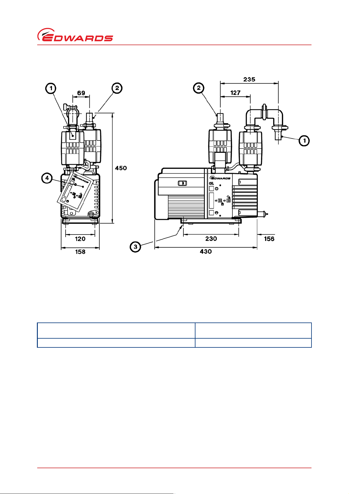
Figure 3 - Dimensions (mm)
1. Outlet
2. Inlet
3. Baseplate mounting holes: 4 x M8
4. Oil change tag
A652–07–880 Issue D
Technical data
2.3.2 Noise and vibration data
Sound pressure: measured at ultimate vacuum 1 metre from the
end of the pump to ISO 11201, 50 Hz electrical supply
Vibration severity: measured at the inlet port to ISO 2372 (1974) Class 1C
50 dB(A)
2.4 Electrical data
Note: Edwards recommends using fuses of the maximum ratings specified in Tables 1 and 2. Do not use fuses of a
higher rating.
The dual-voltage, dual-frequency motor is designed for a single-phase electrical supply and is suitable for 50 Hz or
60 Hz operation. The motor can be manually switched between nominal supply voltages of 110-120 V and 220-240 V
(refer to Section 3.10.1).
When starting a cold pump, the motor will draw a start-up current for up to several seconds, therefore use a
slow-blow fuse to prevent unnecessary fuse failure during pump start-up. Within five minutes, as the oil in the pump
warms up, the current drawn will slowly reduce to the full load current specified in Tables 1and 2.
© Edwards Limited 2014. All rights reserved. Page 7
Edwards and the Edwards logo are trade marks of Edwards Limited.
Page 14

A652–07–880 Issue D
Technical data
Table 1 - Electrical data (pumps with Item Numbers -903 or -906)
Nominal supply
(V)
220-240 50 450 3.4 5
230-240 60 550 3.0 5
110 50 450 6.8 13
115-120 60 550 6.9 13
Table 2 - Electrical data (pumps with Item Numbers -904)
Nominal supply
(V)
200 50 450 4.2 5
200-210 60 550 4.1 5
100 50 450 8.3 13
100-105 60 550 8.0 13
Frequency
(Hz)
Frequency
(Hz)
Power
(W)
Power
(W)
Full load
current (A)
Full load
current (A)
Maximum
fuse rating (A)
Maximum
fuse rating (A)
2.5 Lubrication data
Note: Edwards Safety Data sheets for rotary pump oils are available on request.
Recommended oil* Edwards Ultragrade 19 (hydrocarbon oil)
Oil capacity
Maximum 0.70 l
Minimum 0.42 l
* To operate the E-LAB 2 when the ambient temperature is outside the limits specified in Section 2.1, a different
oil may be required.
2.6 Materials of construction
The surfaces of the pump that are exposed to the process vapours pumped are free from copper, zinc and cadmium.
Other materials of construction include cast iron, aluminium, fluoroelastomer, nitrile, chemically resistant polymers,
nickel and stainless steel.
Page 8 © Edwards Limited 2014. All rights reserved.
Edwards and the Edwards logo are trade marks of Edwards Limited.
Page 15

3 Installation
WARNING
WARNING
WARNING
3.1 Safety
The E-LAB 2 is not recommended for pumping hazardous substances.
Obey the safety instructions in this Section and take note of appropriate precautions. Failure to
observe these instructions may result in injury to people and damage to equipment.
Do not expose any part of the human body to vacuum as it can cause injury.
A652–07–880 Issue D
Installation
Ensure that the pump is suitable for the application. If there is any doubt, refer to the Edwards guidelines in
the Vacuum Pump and Vacuum Systems Safety manual. (See Associated publications at the end of the
Content list.)
A suitably trained and supervised technician must install the pump.
Wear the appropriate safety clothing when coming into contact with contaminated components.
Vent and purge the vacuum system before starting installation work.
Ensure that the installation technician is familiar with the safety procedures which relate to the pump oil
and the products handled by the E-LAB 2. Take suitable precautions to avoid the inhalation of oil mist and
excessive skin contact with pump oil, as prolonged exposure can be harmful.
Disconnect other components in the pumping system from the electrical supply so that they cannot be
operated accidentally.
Ensure that the inlet catchpot, outlet oil mist filter and the gas ballast oil return kit are correctly fitted as
described in the following sections.
Safely route any cables and pipes to prevent a trip hazard.
3.2 System design considerations
Consider the following points when designing the pumping system:
Use a suitable valve to isolate the pump from the vacuum system to allow the pump to warm up before
pumping condensable vapours or to maintain vacuum when the pump is switched off.
Avoid high levels of heat input to the pump from the process gases, otherwise the pump may overheat and
seize.
If the pump is used in a high ambient temperature environment and has a high gas throughput, the
temperature of the pump body may exceed 70 ºC. Fit suitable guards to prevent contact with hot surfaces.
Make sure that the exhaust pipeline cannot become blocked. If the system has an exhaust isolation valve,
make sure that the pump cannot operate with the valve closed.
© Edwards Limited 2014. All rights reserved. Page 9
Edwards and the Edwards logo are trade marks of Edwards Limited.
Page 16

A652–07–880 Issue D
Installation
3.3 Unpack and inspect
Remove all packing materials and protective covers and inspect the equipment. If any of the equipment is damaged,
notify the supplier and the carrier in writing within three days. State the Item Number of the equipment together
with the order number and the supplier’s invoice number. Retain all the packing materials for inspection. Do not use
the equipment if it is damaged.
Check that the items listed in Table 3 have been received. If any item is missing, notify the supplier in writing within
three days.
If the E-LAB 2 is not to be used immediately, replace the protective covers. Store the E-LAB 2 in suitable conditions,
as described in Section 6.1.
Table 3 - Checklist of components
Qty Description Check (
1 E-LAB 2 Pump (with oil change tag fitted)
1Oil mist filter
1Inlet catchpot
6 Clamping rings
4Co-Seals
1 Centring ring and O-ring
2Elbows
2 Hose adaptors
1 Electrical supply cable *
Gas ballast oil return kit, which contains:
1 Oil return assembly
1 Drain adaptor
1Restrictor
1 Flexible oil-return tube
2Hose clips
* Not supplied with pumps with Item Number A652-07-903; see Section 3.10.2.
)
3.4 Locate the pump
The E-LAB 2 has a lifting handle that can be used to move the pump by hand. If using mechanical lifting equipment,
do not attach the equipment to the handle; for stability, use slings around the motor and the pump body.
Provide a firm, level platform for the E-LAB 2. Locate the E-LAB 2 so that the oil level sight glass (Figure 1, item 8)
and the oil change tag (10) are visible, and so that the oil filler plug (7) and oil drain plug are (9) accessible.
If the E-LAB 2 will be located inside an enclosure, make sure that there is adequate ventilation at both ends of the
pump, so that the ambient temperature around the pump does not exceed 40 °C. There must be a minimum space
of 25 mm between the pump and the enclosure walls.
Page 10 © Edwards Limited 2014. All rights reserved.
Edwards and the Edwards logo are trade marks of Edwards Limited.
Page 17

A652–07–880 Issue D
3.5 Fill the pump with oil
Fill the pump with oil as described below. Refer to Section 2 for the recommended oil.
1. Remove one of the oil filler-plugs (Figure 1, item 7).
2. Pour oil into the pump until the oil level just reaches the MAX mark on the bezel at the top of the sight glass (8).
If the oil level goes above the MAX mark, remove the drain plug (9) and drain the excess oil from the pump.
3. After a few minutes, recheck the oil level. If the oil level is now below the MAX mark, pour more oil into the
pump.
4. Refit the oil filler-plug. Tighten the plug firmly by hand. Do not overtighten.
3.6 Fit the outlet oil mist filter
1. Ensure that the pump outlet (Figure 4, item 17) is clean, then place one of the Co-Seals (15) on the outlet.
2. Place the oil mist filter inlet (14) on the pump outlet so that the flow arrow on the lower half of the filter body
(see Figure 8) points upwards away from the pump outlet and the drain plug points towards the oil filler plugs
(as shown in Figure 5).
3. Use one of the clamping rings (Figure 4, item 16) to secure the oil mist filter to the pump.
Installation
4. Use another Co-Seal (3) and clamping ring (2) to secure one of the elbows (4) to the mist filter outlet (12);
ensure that the horizontal part of the elbow points towards the front of the pump (as shown in Figure 3).
5. Use another Co-Seal (5) and clamping ring (6) to secure the other elbow (8) to the elbow already fitted; ensure
that the free end of the elbow points vertically downwards (as shown on Figure 4).
6. Use another Co-Seal (9) and clamping ring (10) to secure one of the hose adaptors (11) to the elbow.
3.7 Fit the gas ballast oil return assembly
1. Remove the drain plug (Figure 8, item 4) from the drain port on the oil mist filter.
2. Fit the drain adaptor (Figure 5, item 8) to the drain port on the oil mist filter.
3. Turn the gas ballast control on the pump (Figure 4, item 18) to position ‘II’. Push the control down (against the
spring), turn the control anticlockwise to release it, then remove the control from the pump. Leave the spring in
position in the gas ballast port in the pump.
4. Lift the pump handle (Figure 1, item 15). Fit the oil return assembly (Figure 5, item 5) to the gas ballast port on
the pump, push the assembly down (against the spring) and turn the assembly clockwise to secure it to the
pump. When the assembly is correctly secured to the pump, the nozzle (4) should be over position ‘0’ marked on
the top of the pump (see detail B).
5. Cut a suitable length from the flexible oil-return tube. The routing of the tube (3) must be approximately as
shown in Figure 5. When fitted, the tube must not be taut and there must be no tight bends in the tube. Ensure
that the ends of the oil-return tube are free of burrs and that they are squarely cut (that is, the cut faces are at
a right angle to the length of the tube).
6. Fit the restrictor (7) into the end of the tube, then fit the same end of the tube to the drain adaptor on the oil
mist filter.
7. Fit the other end of the tube to the nozzle (4) on the oil return assembly (5).
8. Use the hose clips (2) to secure the ends of the flexible oil-return tube (3).
© Edwards Limited 2014. All rights reserved. Page 11
Edwards and the Edwards logo are trade marks of Edwards Limited.
Page 18

A652–07–880 Issue D
1. Hose adaptor
2. Clamping ring
3. Co-Seal
4. Elbow
5. Co-Seal
6. Clamping ring
7. Co-Seal
8. Elbow
9. Co-Seal
10. Clamping ring
11. Hose adaptor
12. Oil mist filter outlet
13. Outlet oil mist filter
14. Oil mist filter inlet
15. Co-Seal
16. Clamping ring
17. Pump outlet
18. Gas ballast control
19. Pump inlet
20. Clamping ring
21. O-ring, centring ring and filter
22. Inlet catchpot outlet
23. Inlet catchpot drain plug
24. Inlet catchpot
25. Inlet catchpot inlet
26. Clamping ring
27. O-ring and centring ring
Installation
Figure 4 - Fit the inlet trap and oil mist filter
Page 12 © Edwards Limited 2014. All rights reserved.
Edwards and the Edwards logo are trade marks of Edwards Limited.
Page 19

Figure 5 - Fit the gas ballast oil return assembly
A. Side view (pump inlet and inlet
catchpot omitted for clarity)
B. Top view
1. Oil mist filter
2. Hose clip
3. Flexible oil-return tube
4. Nozzle
5. Oil return assembly
6. E-LAB 2 pump
7. Restrictor
8. Drain adaptor
A652–07–880 Issue D
Installation
© Edwards Limited 2014. All rights reserved. Page 13
Edwards and the Edwards logo are trade marks of Edwards Limited.
Page 20

A652–07–880 Issue D
1. Screws (3 off)
2. Indentation (low gas ballast flow position)
3. Indentations (high gas ballast flow position)
4. Indentation
5. Restrictor plate
Installation
3.8 Select the gas ballast flow rate (optional)
Note: Use the procedure below to change the gas ballast flow rate after the E-LAB 2 has been used. The pump
must be switched off, allowed to cool and isolated from the electrical supply before doing the following
procedure.
The oil return assembly is supplied configured for high gas ballast flow rate. If required, adjust the gas ballast flow
rate using the following procedure.
1. Undo and remove the three screws (Figure 6, item 1) which secure the restrictor plate (5); do not dismantle the
assembly.
2. The restrictor plate (5) has circular indentations (2 and 3); the position of these indentations with respect to the
indentation (4) on the oil return assembly identifies the gas ballast flow setting. Turn the restrictor plate to the
required position:
To select no gas ballast flow, turn the restrictor plate so that none of the indentations (2 and 3) are aligned
with the indentation (4) on the oil return assembly.
To select low gas ballast flow, turn the restrictor plate so that the single indentation (2) is aligned with the
indentation (4) on the oil return assembly.
To select high gas ballast flow, turn the restrictor plate so that the two indentations (3) are aligned with the
indentation (4) on the oil return assembly.
3. Refit and tighten the three screws (1).
Figure 6 - Select the gas ballast flow rate
Page 14 © Edwards Limited 2014. All rights reserved.
Edwards and the Edwards logo are trade marks of Edwards Limited.
Page 21

A652–07–880 Issue D
CAUTION
3.9 Fit the inlet catchpot
1. Ensure that the pump inlet (Figure 4, item 19) is clean and that the centring ring and filter assembly (supplied
with the pump) is in place on the inlet.
2. Place the inlet catchpot (24) on the pump inlet so that the drain plug (23) points towards the front of the pump
and the arrow on the upper half of the body points towards the pump inlet, as shown on Figure 4.
3. Secure the inlet catchpot to the pump using a clamping ring (20).
4. Secure the hose adaptor (1) to the inlet (25) of the inlet catchpot using an O-ring and centring ring (27) and
clamping ring (26).
3.10 Electrical installation
3.10.1 Check and configure the motor
Ensure that the motor is correctly configured for the electrical supply. If the motor is configured for 110 V
operation and the pump is operated with a 240 V supply, the motor will be damaged.
Installation
Ensure that the voltage shown on the voltage selector switch (Figure 7, item 3) in the motor cover corresponds with
the local electrical supply voltage. If it does not, change the configuration of the pump motor to match the local
electrical supply voltage; use the following procedure.
Use the following procedure to change the configuration of the pump motor:
1. Undo the two retaining screws (6) securing the voltage selector switch cover (5).
2. Remove the voltage selector switch cover (5) and toggle the voltage selector switch (3) into the alternate
position.
3. Invert the voltage selector switch cover (5) and refit over the voltage selector switch (3).
4. Refit the two retaining screws (6).
© Edwards Limited 2014. All rights reserved. Page 15
Edwards and the Edwards logo are trade marks of Edwards Limited.
Page 22

A652–07–880 Issue D
A. Top view of motor
B. View of voltage selector switch cover
C. View of On/off switch
1. Terminal box
2. Electrical inlet connector
3. Voltage selector switch
4. On/off switch
5. Voltage selector switch cover
6. Retaining screws
7. Position 'I' (on)
8. Position '0' (off)
Installation
Figure 7 - Motor voltage configuration
Page 16 © Edwards Limited 2014. All rights reserved.
Edwards and the Edwards logo are trade marks of Edwards Limited.
Page 23

A652–07–880 Issue D
WARNING
3.10.2 Connect the pump to the electrical supply
Ensure that the electrical installation of the E-LAB 2 conforms with local and national safety
requirements. It must be connected to a suitably fused and protected electrical supply and a
suitable earth (ground) point.
Notes: 1. In the UK, if a 13 A plug is used, it must comply with BS1363A and be fitted with a 13 A fuse that complies
with BS1362.
2. To prevent automatic restart of the pump motor if the electrical supply is restored after an electrical
supply failure, connect the pump to the electrical supply through suitable control equipment which
must be reset manually after an electrical supply failure.
3. Make the electrical connections to the pump motor with an IEC 320 cable socket (cold condition type)
that satisfies local electrical standards.
E-LAB 2 pumps with Item Numbers A652-07-904 and A652-07-906 are supplied with an electrical supply cable with a
moulded IEC connector at one end, and with the other end of the cable fitted with a plug suitable for the local
electrical supply. E-LAB 2 pumps with Item Number A652-07-903 are not supplied with an electrical supply cable; a
suitable electrical supply cable must be ordered separately. Use the following procedure to connect the electrical
supply to the pump:
Installation
1. Ensure that the on/off switch on the motor (Figure 7, item 4) is in the ‘off’ position.
2. Insert the moulded IEC connector at the end of the cable into the electrical inlet connector on the motor (2).
3. Connect the plug on the other end of the cable to the electrical supply. If required, remove plug and connect the
wires in the cable to the correct terminals of the electrical supply; connect the wires as follows:
Connect the green and yellow wire to earth (ground).
Connect the blue wire to neutral.
Connect the brown wire to live.
© Edwards Limited 2014. All rights reserved. Page 17
Edwards and the Edwards logo are trade marks of Edwards Limited.
Page 24

A652–07–880 Issue D
CAUTION
CAUTION
WARNING
Installation
3.10.3 Check the direction of rotation
Ensure that the pump motor rotates in the correct direction. If it does not, the pump and the vacuum system
can become pressurised.
1. Watch the motor cooling fan through the motor fan cover (Figure 1, item 13).
2. Use the on/off switch (12) to switch on the electrical supply to the motor for a few seconds.
3. Check that the motor cooling fan rotates in the correct direction (14) shown by the arrow on the motor fan
cover. If the direction of rotation is incorrect, switch off the electrical supply immediately and contact the
supplier or Edwards for advice.
3.11 Inlet and outlet connections
Connect the exhaust to a suitable treatment plant to prevent the discharge of dangerous gases and
vapours to the surrounding atmosphere.
Ensure that the outlet hose is routed below the level of the pump outlet. If not, condensates may drain back
into the pump and damage it.
Use suitable 1/2-inch inside diameter hose to connect the vacuum system to the inlet (Figure 1, item 3) on the inlet
catchpot and to connect the outlet (5) on the oil mist filter to the exhaust extraction system.
3.12 Leak test the system
Leak test the system after installation is complete and seal any leaks found to prevent leakage of hazardous
substances out of the system and leakage of air into the system.
Page 18 © Edwards Limited 2014. All rights reserved.
Edwards and the Edwards logo are trade marks of Edwards Limited.
Page 25

A652–07–880 Issue D
WARNING
4 Operation
Note: At high inlet pressures (above 200 mbar, 2 x 10⁴Pa), the gas ballast oil return assembly will not work
correctly. If oil is to be returned to the pump when the pump is operated at continuous, high inlet
pressures, contact the supplier or Edwards for advice.
4.1 Start-up procedure
Ensure that the system design does not allow the exhaust pipeline to be blocked.
If the oil is contaminated, or if the pump temperature is below 12 °C, or if the electrical supply voltage is more than
10% below the lowest voltage specified on the voltage indicator (Figure 7, item 3), the pump may operate at a
reduced speed for a few minutes. If the pump continues to operate at reduced speed, the motor thermal overload
device will open and stop the pump. When the motor has cooled, the thermal overload device will reset automatically
and the pump will restart.
1. Check that the pump oil level is between the MAX and MIN marks on the bezel of the oil level sight-glass; if it is
not, refer to Section 5.4.
Operation
2. Use the on/off switch (Figure 1, item 12) to switch on the electrical supply to the pump.
4.2 To achieve ultimate vacuum/pump condensable vapours
If the E-LAB 2 does not achieve the performance specified in Section 2, make sure that this is not due to system design
before contacting the or Edwards for advice. In particular, the vapour pressure of all materials used in the vacuum
system (including pump oil, see below) must be much lower than the specified ultimate vacuum of the pump. Refer
to Section 5.14.2 for a list of possi ble causes for failure to achieve the specified performance; note however that the
most common causes are:
The pressure measurement technique or gauge head is unsuitable or the gauge head is faulty.
An oil other than the recommended oil has been used and the vapour pressure of the oil is higher than the
specified ultimate vacuum of the pump.
Use the following procedure to achieve ultimate vacuum:
1. Isolate the E-LAB 2 from the vacuum system and operate the E-LAB 2 for at least 1 hour (or overnight) to
thoroughly purge the oil of contaminants.
2. Open the vacuum system isolation-valve and pump down to ultimate vacuum.
After pumping condensable vapours, if necessary, the oil can be decontaminated: use the procedure in Section 4.3.
© Edwards Limited 2014. All rights reserved. Page 19
Edwards and the Edwards logo are trade marks of Edwards Limited.
Page 26

A652–07–880 Issue D
Operation
4.3 To decontaminate the oil
The oil in the pump should be clear; if the oil is cloudy or discoloured, it is contaminated with process vapours.
1. Look at the condition of the oil in the oil level sight glass (Figure 1, item 8). If the oil is cloudy or discoloured,
continue with the procedure at Step 2 below.
2. Close the vacuum system isolation valve.
3. Operate the pump until the oil is clear.
4.4 Unattended operation
The E-LAB 2 is designed for unattended operation under the normal operating conditions specified in Section 2.
However, Edwards recommends checking the pump at regular intervals of not more than 14 days, or more frequently
if pumping high volumes of gas or vapour.
To automatically decontaminate the pump oil, and to ensure that the correct pump operating temperature is
maintained, Edwards recommends controlling the electrical supply to the pump and the operation of the vacuum
system isolation valve through a time switch: refer to Table 4.
The motor is protected by an overload device which isolates the E-LAB 2 from the electrical supply when critical
temperature or current levels are exceeded. The overload device resets automatically when the motor has cooled.
When checking the E-LAB 2, make sure that the pump is not going through a repetitive cycle of thermal overload
failures and automatic resets. If necessary, reduce the thermal load from the pumped gases, to prevent overheating
of the pump.
Table 4 - Recommended time switch settings
Time Pump operation Isolation-valve operation Function
At least half an hour before
the pump is required for use
During operation Leave on Open or closed, as
At least half an hour after
use
After the decontamination
time
Switch on Closed Pump warm-up time
Maintain the operating
required by pumping
system operation
Leave on Closed Decontaminate the pump oil
Switch off Closed Ready for future use
temperature of the pump,
decontaminate the pump oil
4.5 Shut down
Edwards recommends, as described in the procedure below, decontaminating the oil before shutting down the pump;
this will prevent damage to the pump by the contaminates in the oil.
1. Refer to Section 4.3 and decontaminate the oil, as required.
2. Close the vacuum system isolation valve (if not already closed).
3. Use the on/off switch to switch off the pump.
4. Switch off the electrical supply to the pump.
Page 20 © Edwards Limited 2014. All rights reserved.
Edwards and the Edwards logo are trade marks of Edwards Limited.
Page 27

A652–07–880 Issue D
WARNING
5Maintenance
5.1 Safety
Obey the safety instructions in this Section and take note of appropriate precautions. Failure to
observe these instructions may result in injury to people and damage to equipment.
Ensure that maintenance is done by a suitably trained and supervised technician. Obey local and national
safety requirements.
Ensure that the maintenance technician is familiar with the safety procedures which relate to the pump oil
and the products processed by the pumping system.
Check that all required parts are available and of the correct type before starting work.
Isolate the pump and other components from the electrical supply so that they cannot be operated
accidentally.
Allow the pump to cool for at least 3 hours before starting maintenance work. Make sure the pump is
switched off in case the thermal overload device restarts the pump.
Maintenance
Do not reuse O-rings and seals.
After maintenance is completed, recheck the direction of pump rotation if the electrical supply has been
disconnected.
The pump, pump-oil, inlet catchpot, outlet oil mist filter and gas ballast oil return kit will be contaminated
with the process chemicals that have been pumped during operation. Ensure that the pump is
decontaminated before maintenance and that adequate precautions are taken to protect people from the
effects of dangerous substances.
Do not touch or inhale the thermal breakdown products of fluorinated materials which may be present if the
pump has been heated to 310°C and above. Fluorinated materials are safe in normal use but can decompose
into very dangerous substances (which may include hydrofluoric acid) if they are heated to 310 °C and
above. The pump may have overheated if it was misused or if it was in a fire. Safety Data sheets for
fluorinated materials used in the pump are available on request: contact the supplier or Edwards.
© Edwards Limited 2014. All rights reserved. Page 21
Edwards and the Edwards logo are trade marks of Edwards Limited.
Page 28

A652–07–880 Issue D
Maintenance
5.2 Maintenance plan
The plan shown in Table 5 details the routine maintenance operations necessary to maintain E-LAB 2 pumps in normal
use. Instructions for each operation are given in the section shown.
Table 5 - Maintenance plan
Operation Frequency Refer to Section
Check the liquid level in the inlet catchpot Weekly 5.3
Check the pump oil level Monthly 5.4
Replace the pump oil Every 3000 hours 5.5
Inspect the oil mist filter elements Every 6 months 5.6
Inspect and clean the pump inlet filter Yearly 5.7
Inspect and clean the oil return assembly Yearly 5.8
Clean the pump oil level sight glass Yearly 5.9
Clean the motor fan cover Yearly 5.10
Clean and overhaul the pump Every 15000 hours 5.11
Test the motor condition Every 15000 hours 5.12
Fit new blades to the pump Every 30000 hours 5.13
More frequent maintenance may be required if the pump is used to pump corrosive or abrasive gases and vapours,
such as solvents, organic substances and acids. In these circumstances, Edwards recommends replacing the pump
seals every year. Refer to Section 7 for details of available spares. If necessary, adjust the maintenance plan
according to experience.
When maintaining the E-LAB 2, use Edwards spares and maintenance kits; these contain all of the components
necessary to complete maintenance operations successfully. The Item Numbers of the spares and kits are given in
Section 7.
5.3 Check the liquid level in the inlet catchpot
Look at the level of fluid in the inlet catchpot (Figure 1, item 4). If the level is close to or above the MAX level mark:
1. Place a suitable container under the drain plug (Figure 4, item 23).
2. Remove the drain plug and allow the fluid to drain out of the inlet catchpot.
3. Refit the drain plug to the inlet catchpot.
4. Dispose of the fluid safely; refer to Section 6.
Page 22 © Edwards Limited 2014. All rights reserved.
Edwards and the Edwards logo are trade marks of Edwards Limited.
Page 29

A652–07–880 Issue D
5.4 Check the pump oil level
Note: If required, the oil level can be checked while the pump is operating, however, the pump must be switched
off and the pump and other components in the pumping system must be isolated from the electrical supply
before pouring oil into the pump.
1. Check that the oil level in the sight glass (Figure 1, item 8) is between the MAX and MIN level marks on the bezel
of the sight glass.
2. If the oil level is near to or below the MIN level mark, remove one of the filler plugs (7) and pour more oil into
the reservoir until the oil reaches the MAX level mark. If the oil level goes above the MAX mark, remove the
drain plug (9) and drain the excess oil from the pump. Refit the filler plug.
3. If the oil is contaminated, drain and refill the pump with clean oil as described in Section 5.5.
5.5 Replace the pump oil
The diagrams on the side panels of the pump and on the oil change tag give guidance on when to replace the pump
oil. When the colour of the oil is approximately the same colour as the middle bar on the side panel (or tag), replace
the oil as described below. If the pump continues to be used and the oil condition deteriorates until the colour of the
oil is approximately the same as the lower bar on the side panel (or tag), clean and overhaul the pump as described
in Section 5.11.
Maintenance
Use the following procedure to replace the pump oil:
1. Operate the pump for approximately ten minutes to warm the oil, then use the on/off switch (Figure 1, item 12)
to switch off the pump. This lowers the viscosity of the oil and enables it to be drained from the pump more
easily.
2. Isolate the pump from the electrical supply and disconnect it from the vacuum system.
3. Remove one of the oil filler plugs (7).
4. Place a suitable block under the pump motor to tilt the pump and place a suitable container under the drain
plug (9). Remove the drain plug and allow the oil to drain into the container.
5. If the oil drained from the pump is contaminated, pour clean oil into the filler hole and allow it to drain out of
the pump. Repeat this step until the oil reservoir in the pump has been thoroughly cleaned.
6. Refit the drain plug, remove the block and reconnect the pump to the vacuum system.
7. Fill a suitable container with clean oil and pour the oil into the filler hole until the oil level reaches the MAX
level mark on the bezel of the sight glass (8).
8. Allow a few minutes for the oil to drain into the pump. If necessary, add more oil. Refit the filler plug.
© Edwards Limited 2014. All rights reserved. Page 23
Edwards and the Edwards logo are trade marks of Edwards Limited.
Page 30

A652–07–880 Issue D
Maintenance
5.6 Inspect the oil mist filter elements
The oil mist filter has an odour element and an oil filter element. The life of the elements in the oil mist filter
depends on the process application. If the filter element becomes blocked, the internal pressure relief valve in the
filter will operate and unfiltered gases and oil mist will pass directly into the exhaust-extraction system.
Inspect the elements as described below. Adjust the frequency in the maintenance plan, if necessary, to ensure that
elements are inspected, and changed if necessary, before the filter element becomes blocked. Replace the odour
element whenever the pump has an oily odour.
1. Undo the clamping ring (Figure 4, item 2) and remove the elbow (4) and Co-Seal (3) from the outlet (12) of the
oil mist filter.
2. Undo and remove the four screws (Figure 8, item 12) that secure the upper body (10) to the lower body (7), then
remove the upper body.
3. Lift out the elements (8, 10) and inspect the outer surface of the elements for contaminates:
If the elements need to be replaced, dispose of them safely (refer to Section 6) and obtain new elements.
If the elements do not need to be replaced, wipe them clean.
4. Wipe clean the inside of the upper body (10) and lower body (7) and the mating surfaces. Do not remove the ‘D’
seal (9).
5. Ensure that the filter element O-ring (5) is in place in the lower body (7), then fit the elements in the lower
body; ensure that the foam sealing rings on the top and bottom of the elements are correctly seated.
6. Refit the upper body (10) to the lower body (7) and secure with the four screws (12) removed in Step 2.
7. Wipe clean the Co-Seal (Figure 4, item 3) and the outlet (12) of the oil mist filter, then place the Co-Seal on the
outlet.
8. Refit the elbow (4) to the outlet and secure with the clamping ring (2).
Page 24 © Edwards Limited 2014. All rights reserved.
Edwards and the Edwards logo are trade marks of Edwards Limited.
Page 31

Figure 8 - The outlet oil mist filter
1. Outlet
2. Odour element seal
3. Pressure relief valve
4. Drain plug
5. Mist filter element O-ring
6. Inlet
7. Lower body (white)
8. Mist filter element
9. ‘D’ seal
10. Upper body (grey)
11. Odour element
12. Securing screws
13. Maximum oil level mark
14. Sight panel
Pump exhaust gas
Oil droplets
A652–07–880 Issue D
Maintenance
© Edwards Limited 2014. All rights reserved. Page 25
Edwards and the Edwards logo are trade marks of Edwards Limited.
Page 32

A652–07–880 Issue D
1. Centring ring and filter assembly
2. O-ring
3. Pump inlet
Maintenance
5.7 Inspect and clean the pump inlet-filter
1. Undo the clamping ring (Figure 4, item 20) and remove the inlet catchpot (24) from the inlet of the pump.
2. Remove the centring ring and filter assembly (Figure 9. item 1) and the O-ring (2) from the inlet of the pump.
Inspect the centring ring and the O-ring. If they are clean, continue at Step 7. If they are not clean, continue at
Step 3.
3. Remove the O-ring (2) from the centring ring and filter assembly (1). Do not allow the O-ring to come into
contact with the cleaning solution.
4. Wash the centring ring and filter assembly in a suitable cleaning solution and allow it to dry.
5. If necessary, wipe the O-ring with a clean, dry, lint-free cloth.
6. Refit the O-ring (2) to the centring ring and filter assembly (1).
7. Refit the O-ring and centring ring and filter assembly to the inlet.
8. Fit the inlet catchpot (Figure 4, item 24) to the pump inlet (19) and secure with the clamping ring (20).
Figure 9 - Pump inlet filter assembly
Page 26 © Edwards Limited 2014. All rights reserved.
Edwards and the Edwards logo are trade marks of Edwards Limited.
Page 33

A652–07–880 Issue D
5.8 Inspect the oil return assembly
5.8.1 Check the installation of the assembly
1. Check that the oil return assembly (Figure 5, item 5) is securely fitted to the pump.
2. Check that the flexible oil return tube (3) is securely fitted to the oil return assembly (5) and to the oil mist
filter (1).
3. Check that there are no blockages in the tube. If the restrictor (7) is blocked, unblock it as described in
Section 5.8.2.
4. Check that the oil return assembly operates correctly.
5. Inspect the air intake (Figure 11, item 2). If the air intake is blocked, unblock it as described in Section 5.8.3.
5.8.2 Unblock the restrictor (if necessary)
1. Switch off the pump and allow it to cool to a safe temperature. Isolate the pump from the electrical supply so
that it cannot be operated accidentally.
2. Undo and remove the hose clip (Figure 5, item 2) on the oil mist filter end of the oil return tube (3), then
remove the end of the oil return tube from the drain adaptor (8) on the oil mist filter (1).
Maintenance
3. Remove the restrictor (7) from the oil return tube and remove the blockage from the restrictor.
4. Refit the restrictor (7) in the end of the oil return tube (3), fit the end of the oil return tube to the drain adaptor
(8) on the oil mist filter, then use the hose clip (2) to secure the end of the oil return tube.
5. Reconnect the pump to the electrical supply.
5.8.3 Unblock the air intake (if necessary)
1. Switch off the pump and allow it to cool to a safe temperature. Isolate the pump from the electrical supply so
that it cannot be operated accidentally.
2. Undo and remove the three screws (Figure 11, item 1) that secure the top piece (3) and remove the top piece
from the oil return assembly.
3. Use a suitable tool to remove the blockage from the air intake (2).
4. Refit the top piece (3) to the oil return assembly and secure with the three screws (1), then reconnect the pump
to the electrical supply.
© Edwards Limited 2014. All rights reserved. Page 27
Edwards and the Edwards logo are trade marks of Edwards Limited.
Page 34

A652–07–880 Issue D
1. Screws (2 off M6 x 20)
2. Bezel
3. Sight glass
4. O-ring
5. Oil box
Maintenance
5.9 Clean the pump oil level sight glass
1. Move the oil change tag (Figure 1, item 10) to the side of the pump in order to access the oil level sight glass (8).
2. Drain the oil as described in Section 5.5.
3. Undo the two screws (Figure 10, item 1) and remove the bezel (2), the sight glass (3) and the O-ring (4) from the
oil box (5).
4. Clean the screws, bezel and sight glass with a suitable cleaning solution.
5. Wipe the O-ring with a clean, dry, lint-free cloth.
6. Wipe the sight glass recess in the oil box with the cloth.
7. Refit the O-ring, sight glass and bezel and secure with the two screws.
8. Refill the pump with oil as described in Section 5.5.
9. Check that the sight glass does not leak.
10. Move the oil change tag (Figure 1, item 10) to the front of the pump, over the sight glass.
Figure 10 - Sight glass assembly
Page 28 © Edwards Limited 2014. All rights reserved.
Edwards and the Edwards logo are trade marks of Edwards Limited.
Page 35

Figure 11 - Part sectional view of the oil return assembly
1. Screw
2. Air intake
3. Restrictor plate
4. Expansion chamber
5. Silencer tube
A652–07–880 Issue D
Maintenance
© Edwards Limited 2014. All rights reserved. Page 29
Edwards and the Edwards logo are trade marks of Edwards Limited.
Page 36

A652–07–880 Issue D
Maintenance
5.10 Clean the motor fan cover
If the motor fan-cover and enclosure are not kept clean, the air-flow over the motor can be restricted and the pump
may overheat.
1. Use the On/off switch (Figure 1, item 12) to switch off the pump, then disconnect it from the electrical supply.
2. Use a dry cloth and a soft brush to remove dirt and deposits from the fan cover (13) and enclosure.
5.11 Clean and overhaul the pump
Clean and overhaul the pump as described in the instructions supplied with the clean and overhaul kit (see Section 7).
5.12 Test the motor condition
Test the earth continuity and the insulation resistance of the pump motor in accordance with local regulations for
periodic testing of electrical equipment.
The motor of the E-LAB 2 complies with IEC 1010-1. We recommend that, to maintain compliance with IEC 1010-1,
the earth continuity is less than 0.1Ω and the insulation resistance is greater than 10 MΩ.
If the motor fails these tests, replace the motor.
5.13 Fit new blades to the pump
Fit new blades to the pump as described in the instructions supplied with the blade kit (see Section 7).
Page 30 © Edwards Limited 2014. All rights reserved.
Edwards and the Edwards logo are trade marks of Edwards Limited.
Page 37

A652–07–880 Issue D
5.14 Fault finding
A list of fault conditions and their possible causes is provided here to assist in fault finding. If a fault cannot be
rectified when using this guide, call the nearest Edwards Service Centre for help.
5.14.1 The pump has failed to start
The electrical supply fuse has blown
The electrical supply voltage does not match that of the motor
The outlet pipeline or the oil mist filter is blocked
The oil temperature is below 12 °C
The oil is too viscous
The oil is contaminated
The pump has seized after long storage
The pump has been left to stand after contaminants have been pumped and has seized
The motor is faulty.
Maintenance
5.14.2 The pump has failed to achieve the specified performance (has failed to reach
ultimate vacuum)
The pressure measurement technique or gauge head is unsuitable or gives an incorrect indication of
pressure. For example, a contaminated Pirani gauge can indicate a pressure which is several times higher
than the actual pressure in the system.
The pump is filled with the wrong type of oil
There is a leak in the vacuum system
The oil level is low
The oil is contaminated
Vacuum fittings are dirty or damaged
The inlet catchpot is blocked
The pump has not warmed up.
5.14.3 The pump is noisy
The motor fan cover is damaged
The motor bearings are worn
The oil is contaminated with solid particles.
© Edwards Limited 2014. All rights reserved. Page 31
Edwards and the Edwards logo are trade marks of Edwards Limited.
Page 38

A652–07–880 Issue D
Maintenance
5.14.4 The pump surface temperature is above 100 °C
The ambient temperature is too high
The cooling air supply is insufficient or is too hot
The electrical supply voltage is too high
The oil mist filter or the outlet pipeline is blocked
The oil level is too low
The pump is filled with the wrong type of oil
The oil is contaminated
The process gas is too hot or the throughput is too high.
5.14.5 The vacuum is not fully maintained after the pump is switched off
The gas ballast oil return assembly is incorrectly fitted
The inlet valve pad is damaged
The inlet valve has not closed.
5.14.6 The pumping speed is poor
The connecting pipelines are too small in diameter
The connecting pipelines are too long
The inlet catchpot is blocked.
5.14.7 There is an external oil leak
The outer shaft seal is worn or damaged
The oil box gaskets have deteriorated
There is an oil leak from the gas ballast oil return assembly
There is an oil leak from the drain plug
There is an oil leak from the sight glass.
Page 32 © Edwards Limited 2014. All rights reserved.
Edwards and the Edwards logo are trade marks of Edwards Limited.
Page 39

A652–07–880 Issue D
CAUTION
6 Storage and disposal
6.1 Storage
Observe the storage temperature limits stated in Section 2. Storage below -30 °C will permanently damage the
pump seals.
Note: If a new pump is stored in conditions of high humidity, remove the pump from its cardboard packaging box;
dispose of the box (refer to Section 6.2).
Use the following procedure to store the pump:
1. Shut down the pump as described in Section 4.
2. Disconnect the pump from the electrical supply.
3. Purge the vacuum system and the pump with dry nitrogen and disconnect the pump from the vacuum system.
4. Drain any fluid from the inlet catchpot and drain any oil from the oil mist filter.
Storage and disposal
5. Replace the oil as described in Section 5.5.
6. Place and secure protective covers over the inlet and outlet ports.
7. Store the pump in cool, dry conditions until required for use. When required, prepare and install the pump as
described in Section 3. If the pump has been stored for more than a year, clean and overhaul the pump, as
described in the instructions supplied with the clean and overhaul kit, before installing it.
6.2 Disposal
Dispose of the pump and any components removed from it safely in accordance with all local and national safety and
environmental requirements.
Particular care must be taken with components and waste oil which have been contaminated with dangerous process
substances.
Do not incinerate fluoroelastomer seals and O-rings.
© Edwards Limited 2014. All rights reserved. Page 33
Edwards and the Edwards logo are trade marks of Edwards Limited.
Page 40

A652–07–880 Issue D
This page has been intentionally left blank.
Page 34 © Edwards Limited 2014. All rights reserved.
Edwards and the Edwards logo are trade marks of Edwards Limited.
Page 41

A652–07–880 Issue D
7 Service and spares
7.1 Introduction
Edwards products, spares and accessories are available from Edwards companies in Belgium, Brazil, China, France,
Germany, Israel, Italy, Japan, Korea, Singapore, United Kingdom, U.S.A and a world-wide network of distributors.
The majority of these centres employ Service Engineers who have undergone comprehensive Edwards training
courses.
Order spare parts and accessories from the nearest Edwards company or distributor. When ordering, state for each
part required:
Model and Item Number of the equipment
Serial number
Item Number and description of part.
7.2 Service
Edwards products are supported by a world-wide network of Edwards Service Centres. Each Service Centre offers a
wide range of options including: equipment decontamination; service exchange; repair; rebuild and testing to factory
specifications. Equipment which has been serviced, repaired or rebuilt is returned with a full warranty.
Service and spares
Local Service Centres can also provide Edwards engineers to support on-site maintenance, service or repair of
equipment.
For more information about service options, contact the nearest Service Centre or other Edwards company.
7.3 Spares available
Product Item Number
Edwards Ultragrade 19 oil (1 l) H110-25-015
Edwards Ultragrade 19 oil (4 l) H110-25-013
Clean and overhaul kit A652-01-131
Blade kit A652-01-130
Inlet valve kit A652-01-036
Outer shaft seal kit A652-01-134
Electric motor
Pumps with Item Numbers -903 and -906 A652-99-500
Pumps with Item Numbers -904 A652-98-000
Cartridge Kit A652-01-032
Oil mist filter oil element A224-04-198
Oil mist filter odour element (pack of five) A223-04-079
Oil mist filter ‘D’ seal A271-59-535
Gas ballast oil return assembly service kit A505-23-825
Oil change tag (pack of 10) A200-03-017
Side panel (gas ballast side) A652-07-196
Side panel (pump inlet side) A652-07-017
© Edwards Limited 2014. All rights reserved. Page 35
Edwards and the Edwards logo are trade marks of Edwards Limited.
Page 42

A652–07–880 Issue D
This page has been intentionally left blank.
Page 36 © Edwards Limited 2014. All rights reserved.
Edwards and the Edwards logo are trade marks of Edwards Limited.
 Loading...