

Page 1

Instruction Manual
E1M18 and E2M18 Rotary Vacuum Pumps
A343-10-880
Issue P Original
Description Item Number
E1M18, 100/200 V, 50 Hz or 100-105/200-210 V, 60 Hz, single-phase A343-15-904
E1M18, 115/230 V, 60 Hz, single-phase A343-15-981
E1M18, 220 V, 50/60 Hz, single-phase A343-15-920
E1M18, 220-240 V, 50 Hz, single-phase A343-15-912
E1M18, 220-240 V, 50 Hz, or 230-240 V, 60 Hz, single-phase A343-15-903
E1M18, 200-230/380-460 V, 50/60 Hz, three-phase A343-10-940
E1M18, 220-240 V, 50 Hz, or 230-240 V, 60 Hz, single-phase (Amphenol) A343-16-903
E1M18, 110/200-240 V, 50 Hz, or 115-120/200-230 V, 60 Hz, single-phase A343-17-984
E1M18, 110/200-240 V, 50 Hz, or 115-120/200-230 V, 60 Hz, single-phase, fomblin filled A343-25-984
E2M18, 100/200 V, 50 Hz or 100-105/200-210 V, 60 Hz, single-phase A363-15-904
E2M18, 115/230 V, 60 Hz, single-phase A363-15-981
E2M18, 220 V, 50/60 Hz, single-phase A363-15-920
E2M18, 220-240 V, 50 Hz, single-phase A363-15-912
E2M18, 220-240 V, 50 Hz, or 230-240 V, 60 Hz, single-phase A363-15-903
E2M18, 200-230/380-460 V, 50/60 Hz, three-phase A363-10-940
E2M18, 110/200-240 V, 50 Hz, or 115-120/200-230 V, 60 Hz, single-phase A363-17-984
E2M18-FF, 200-230/380-460 V, 50/60 Hz, three-phase A363-21-940
E2M18-FF, 100/200 V, 50/60 Hz, single-phase A363-25-904
E2M18, 220-240 V, 50 Hz, single-phase A363-25-912
E2M18, 110/200-240 V, 50 Hz, or 115-120/200-230 V, 60 Hz, single-phase, fomblin filled A363-25-984
Page 2

Declaration of Conformity
We, Edwards,
Crawley Business Quarter,
Manor Royal,
Crawley,
West Sussex, RH10 9LW, UK
declare under our sole responsibility, as manufacturer and person within the EU authorised to assemble the
technical file, that the product(s)
E1M18 and E2M18 Rotary Vacuum Pumps
AXXX – YY – ZZZ
Pump Type Variant Motor Description
XXX YY ZZZ
343 = E1M18 10 to 99 903 = 220 V, 0.75 kW
363 = E2M18 904 = 100/200 V
912 = 220 V, 0.55 kW
920 = 220 V, 50/60 Hz
930 = 220 V, 0.75 kW
940 = 200-230/380-460 V, 50/60 Hz, 3 phase
981 = 115/230 V, 60 Hz
984 = 110/200-240 V, 0.75 kW – switched to High volt
986 = 110/200-240 V, 0.75 kW – switched to Low volt
to which this declaration relates is in conformity with the following standard(s) or other normative
document(s)
EN61010-1:2001* Safety R equirements for Electrical Equipment for Measurement, Control and
EN60034-1: 2010 Rotating electrical machines. Rating and performance
C22.2 No77: 1995# Motors with inherent overheating protection
C22.2 No100: 2004 Motors and Generators
C22.2 61010-1-04: 2004 Safety requirements for electrical equipment for measurement, Control and
UL61010A: 2002 # Safety requirements for electrical equipment for measurement, Control and
UL1004: 1994 Electric Motors
EN50581: 2012 Technical Documentation for the Assessment of Electrical and Electronic
* 1-phase pumps only. The pumps comply with EN 61010-1 when installed in accordance with the
#
1-phase pumps only. Canadian Standards Authority and Underwriters Laboratory.
and fulfils all the relevant provisions of
2006/42/EC Machinery Directive
2006/95/EC Low Voltage Directive
2004/108/EC Electromagnetic Compatibility (EMC) Directive
2011/65/EU** Restriction of Certain Hazardous Substances (RoHS) Directive
** i.e. The product(s) contain less than - 0.1wt% for hexavalent chromium, lead, mercury, PBB and PBDE; 0.01wt%
for cadmium - in homogeneous materials (subject to the exemptions allowed by the Directive). The RoHS Directive
does not legally apply to industrial vacuum equipment until July 2019 (July 2017 for instruments).
Note: This declaration covers all product serial numbers from the date this Declaration was signed onwards.
20.05.2013, Burgess Hill
Peter Meares
GV Technical Support Manager
This product has been manufactured under a quality system registered to ISO9001
Laboratory Use. General Requirements
laboratory use – Part 1: General requirements
laboratory use – Part 1: General requirements
Products with respect to the Restriction of Hazardous Substances
instruction manual supplied with the pumps.
Date and Place
Add ref number here e.g. P200-00-000 Issue A
All new numbers should be logged in P-
P200-00-600 Issue F
Numbers spreadsheet on Publicit in P-Numbers
folder.
Document Template: 02B01010 Attachment 4 Iss. 1
Page 3

A343-10-880 Issue P
Contents
Section Page
1 Introduction .......................................................................................1
1.1 Scope and definitions ................................................................................................... 1
1.2 ATEX directive implications ............................................................................................ 2
1.3 Description ................................................................................................................ 4
1.4 Gas-ballast ................................................................................................................ 4
2 Technical data ....................................................................................5
2.1 Operating and storage conditions ..................................................................................... 5
2.2 Performance ..............................................................................................................5
2.3 Mechanical data .......................................................................................................... 6
2.4 Lubrication data ......................................................................................................... 6
2.5 Electrical data ............................................................................................................ 7
3 Installation ............................................... ................................... ..... 11
3.1 Safety .....................................................................................................................11
3.2 System design ...........................................................................................................11
3.3 Unpack and inspect .....................................................................................................12
3.4 Locate the pump ........................................................................................................12
3.5 Fill the pump with oil ..................................................................................................13
3.6 Electrical installation: single-phase motors ........................................................................13
3.6.1 Introduction .............................................................................................................13
3.6.2 Standard single-phase motors ........................................................................................14
3.6.3 Amphenol version single-phase motors ..............................................................................14
3.6.4 110/200-240 V 50 Hz or 115-120/200-230 V 60 Hz single-phase motors .......................................14
3.7 Electrical installation: three-phase motors .........................................................................18
3.7.1 Connect the electrical supply to the motor ........................................................................18
3.7.2 Check the direction of rotation ......................................................................................19
3.8 Connect the pump inlet ................................................................................................19
3.9 Connect the pump outlet ..............................................................................................21
3.10 Gas-ballast inlet connection ..........................................................................................22
3.11 Leak test the system ...................................................................................................22
Contents
4 Operation ........................................................................................ 23
4.1 ATEX directive implications ...........................................................................................23
4.1.1 Introduction .............................................................................................................23
4.1.2 Flammable/pyrophoric materials ....................................................................................23
4.1.3 Gas purges ...............................................................................................................24
4.2 Gas-ballast control .....................................................................................................24
4.3 Start-up ..................................................................................................................25
4.4 To achieve ultimate vacuum ..........................................................................................25
4.5 To pump condensable vapours ........................................................................................26
4.6 To decontaminate the oil ..............................................................................................26
4.7 Unattended operation ..................................................................................................26
4.8 Shut-down ................................................................................................................26
5 Maintenance ..................................................................................... 27
5.1 Safety information ......................................................................................................27
5.2 Maintenance plan .......................................................................................................27
5.3 Check the oil-level .....................................................................................................28
5.4 Replace the oil ..........................................................................................................28
dcs/8832/04/11
© Edwards Limited 2011. All rights reserved. Page i
Edwards and the Edwards logo are trademarks of Edwards Limited.
Page 4

A343-10-880 Issue P
Contents
5.5 Inspect and clean the inlet-filter .....................................................................................29
5.6 Clean the gas-ballast filter ............................................................................................30
5.7 Clean the motor fan-cover and enclosure ..........................................................................30
5.8 Clean and overhaul the pump .........................................................................................30
5.9 Replace the run capacitor and test the motor .....................................................................31
5.10 Fit new blades ...........................................................................................................31
5.11 Fault finding .............................................................................................................31
5.11.1 Introduction .............................................................................................................31
5.11.2 The pump has failed to start ..........................................................................................31
5.11.3 The pump fail to achieve specified performance (failure to reach ultimate vacuum) ......................32
5.11.4 The pump is noisy .......................................................................................................32
5.11.5 The pump surface temperature is above 100 °C ...................................................................32
5.11.6 The vacuum is not maintained after the pump is switched off ..................................................33
5.11.7 The pumping speed is poor ............................................................................................33
5.11.8 There is an external oil leak ..........................................................................................33
6 Storage and disposal . ..... .... ..... ..... ..... .................................................. 35
6.1 Storage ...................................................................................................................35
6.2 Disposal ...................................................................................................................35
7 Service, spares and accessories .............................................................. 37
7.1 Introduction .............................................................................................................37
7.2 Service .................................................................................................................... 37
7.3 Spares ..................................................................................................................... 37
7.4 Accessories ...............................................................................................................38
7.4.1 Introduction .............................................................................................................38
7.4.2 Inlet catchpot ...........................................................................................................38
7.4.3 Inlet dust filter ..........................................................................................................39
7.4.4 Inlet desiccant trap .....................................................................................................39
7.4.5 Inlet chemical trap .....................................................................................................39
7.4.6 Outlet mist filter ........................................................................................................39
7.4.7 Solenoid operated pipeline valve ....................................................................................41
7.4.8 Foreline trap .............................................................................................................41
7.4.9 Vibration isolators ......................................................................................................41
7.4.10 Oil drain extension .....................................................................................................41
7.4.11 Pump inlet adaptor .....................................................................................................41
7.4.12 Flexible bellows .........................................................................................................41
7.4.13 Pump outlet adaptor ...................................................................................................41
7.4.14 Gas ballast banjo/elbow assembly ...................................................................................41
7.4.15 Gas ballast valve ........................................................................................................41
8 PFPE-prepared EM pumps ............................................ ..... ..... ..... ..... ..... 43
8.1 Summary .................................................................................................................43
8.2 Installation ...............................................................................................................43
8.3 Operation ................................................................................................................43
8.4 Maintenance .............................................................................................................43
For return of equipment, complete the HS Forms at the end of this manual.
Page ii © Edwards Limited 2011. All rights reserved.
Edwards and the Edwards logo are trademarks of Edwards Limited.
Page 5

A343-10-880 Issue P
Illustrations
Figure Page
1 The E1M18/E2M18 pump ................................................................................................ 3
2 Dimensions (mm): key .................................................................................................. 8
3 Electrical supply connection: single-phase motors: 220-240 V 50 Hz and 230-240 V 60 Hz .................15
4 Electrical supply connection: single-phase motors: 100 V 50 Hz, 100-105 V 60 Hz and 115 V 60 Hz ......15
5 Electrical supply connection, single-phase motors: 200 V 50 Hz, 200-210 V 60 Hz and 230 V 60 Hz ......16
6 Electrical supply connection, single-phase motors with Amphenol connector:
220-240 V 50 Hz and 230-240 V 60 Hz ...............................................................................17
7 Motor voltage selection: single-phase motors, 110/200-240 V 50 Hz and 115-120/200-240 V 60 Hz ......18
8 Electrical supply connection, three-phase motors: 200-220 V 50 Hz and 200-230 V 60 Hz .................20
9 Electrical supply connection, three-phase motors: 380-415 V 50 Hz and 460 V 60 Hz .......................21
10 Remove/replace the inlet filter ......................................................................................29
11 Remove/replace the gas-ballast filter ..............................................................................30
12 Accessories ............................................................................................................... 40
Tables
Contents
Table Page
1 Operating and storage conditions ..................................................................................... 5
2 Performance data ........................................................................................................ 5
3 Mechanical data .......................................................................................................... 6
4 Lubrication data ......................................................................................................... 6
5 Electrical data: three-phase motors .................................................................................. 7
6 Electrical data: single-phase motors ................................................................................. 7
7 Checklist of items .......................................................................................................12
8 Motor connection details ..............................................................................................13
9 Maintenance plan .......................................................................................................28
10 Spares item numbers ...................................................................................................37
11 Accessory item numbers ...............................................................................................38
Associated publications
Publication title Publication number
Vacuum pump and vacuum system safety P300-20-000
Vibration isolators A248-01-880
EMF3, EMF10 and EMF20 oil mist filters A462-26-880
© Edwards Limited 2011. All rights reserved. Page iii
Edwards and the Edwards logo are trademarks of Edwards Limited.
Page 6

A343-10-880 Issue P
This page has been intentionally left blank.
Page iv © Edwards Limited 2011. All rights reserved.
Edwards and the Edwards logo are trademarks of Edwards Limited.
Page 7

A343-10-880 Issue P
CAUTION
WARNING
1Introduction
1.1 Scope and definitions
This manual provides installation, operation and maintenance instructions for the Edwards E1M18 and E2M18 rotary
vacuum pumps. You must use the pump as specified in this manual.
Read this manual before you install and operate the pump. Important safety information is highlighted as WARNING
and CAUTION instructions; you must obey these instructions. The use of WARNINGS and CAUTIONS is defined below.
Warnings are given where failure to observe the instruction could result in injury or death to
people.
Cautions are given where failure to observe the instruction could result in damage to the equipment, associated
equipment and process.
Introduction
The units used throughout this manual conform to the SI international system of units of measurement.
The following warning labels are on the pump:
Warning - refer to accompanying documentation.
Warning - risk of electric shock.
Warning - hot surfaces.
Warning - do not block the pump outlet.
© Edwards Limited 2011. All rights reserved. Page 1
Edwards and the Edwards logo are trademarks of Edwards Limited.
Page 8

A343-10-880 Issue P
Introduction
1.2 ATEX directive implications
z This equipment is designed to meet the requirements of Group II Category 3 equipment in accordance with
Directive 94/9/EC of the European P arliament and the Council of 23rd March 1994 on the approximation of
the laws of the Member States concerning equipment and protective systems intended for use in potentially
explosive atmospheres. (The ATEX Directive)
The ATEX Category 3 applies in respect of potential ignition sources internal to the equipment. An ATEX
Category has not been assigned in respect of potential ignition sources on the outside of the equipment as
the equipment has not been designed for use where there is an external potentially explosive atmosphere.
There is no potential source of ignition within the pump during normal operation but there may be pote nt ial
sources of ignition under conditions of predictable and rare malfunction as defined in the Directive.
Accordingly, although the pump is designed to pump flammable materials and mixtures, operating
procedures should ensure that under all normal and reasonably predictable conditions, these materials and
mixtures are not within explosive limits. Category 3 is considered appropriate for the avoidance of ignition in
the case of a rare malfunction which allows flammabl e materials or mixtures to pass through the pump while
within their explosive limits.
z When flammable or pyrophoric materials are present within the equipment you must:
z Not allow air to enter the equipment.
z Ensure that the system is leak tight.
z For further information, please contact Edwards: refer to the Addresses page at the end of this manual for
details of your nearest Edwards company.
Page 2 © Edwards Limited 2011. All rights reserved.
Edwards and the Edwards logo are trademarks of Edwards Limited.
Page 9

Figure 1 - The E1M18/E2M18 pump
1. Oil filler
2. Outlet nozzle
3. Gas-ballast control
4. Gas-ballast inlet
5. Centring-ring and O-ring (supplied)
6. Inlet-port (adaptor flange)
7. Cable-gland/Amphenol connector position
8. Motor terminal box
9. On/Off switch
10.Box section skids
11.Oil drain-plug (gravity drain)
12.Oil sight-glass
13.Pump identification label
14.Oil drip tray
A343-10-880 Issue P
Introduction
Note: A pump with a single-phase motor is shown in this figure.
The motor shown in this figure is not representative of the motor used on the E1/E2M18 pumps with Item
Numbers A343-17-984 and A363-17-984. On these pumps, items 7 and 9 are transposed, with Item 7 being
an IEC60320 16-20 Amp socket.
© Edwards Limited 2011. All rights reserved. Page 3
Edwards and the Edwards logo are trademarks of Edwards Limited.
Page 10

A343-10-880 Issue P
Introduction
1.3 Description
The Edwards E1M18 and E2M18 pumps are shown in Figure 1. Refer to Figure 1 for item numbers in brackets in the
following descriptions.
The E1M18 and E2M18 pumps are direct drive, sliding vane pumps. The E1M18 is a single-stage pump, and the E2M18
is a two-stage pump. The pump is oil-sealed and designed for reliable, long-term operation in both laboratory and
industrial environments. The pump is a free-standing unit. The drive is provided through a fle xible coupling by a
single-phase or three-phase (four pole) motor.
The motors are totally enclosed and are cooled by the motor-coo li ng fan wh ich directs air along the motor fins.
The single-phase motors have a thermal overload device. When the motor is too hot, the thermal overload device
switches off the pump. The thermal overload device has an automatic reset; when the motor cools down, the d evice
resets and the motor will restart. The single phase motors have an on/off switch.
An oil pressure system lubricates the pump shaft bearing surfaces and rotor sealing faces. The pump has an oil
distribution valve which prevents discharge of oil to the pump interior (suckback) after the pump stops. The pumping
chambers are air-tight, so this arrangement prevents air suckback unless the gas-ballast valve is open. For protection
in this case, refer to Section 1.4.
You can inspect the level and condition of oil in the oil box reservoir through the oil sight-glass (12). An oil filler-plug
(1) is fitted to the top of the oil box. The pump has an oil drain-plug (11) to allow gravity oil drain.
The pump has an inlet-port (6), outlet nozzle (2) and gas-ballast control (3). The pump is mounted on two mild steel
box section skids (10) on rubber pads. Details of suitable vibration isolators and other recommended accessori es are
given in Section 7.4.
1.4 Gas-ballast
When you use the pump with high vapour throughputs, you should use the gas-ballast facility to prevent condensation
of the vapours inside the pump. The con densates will contaminate the oil, will cause performance to deteri orate and
may cause corrosion of the pump mechanism.
Air (or an inert gas) can be introduced into the pump mechanism through the gas-ballast control (Figure 1, item 3).
The gas-ballast control is a multi-turn valve:
z From the closed position, the first two turns of the gas-ballast control provide an additional oil-feed to the
pump mechanism, but do not introduce gas-ballast into the pump. The additional oil-feed improves the
lubrication and sealing of the pump mechanism.
z With further turns of the gas-ballast control, the gas-ballast flow into the pump increases from zero flow,
until the valve is fully open.
Page 4 © Edwards Limited 2011. All rights reserved.
Edwards and the Edwards logo are trademarks of Edwards Limited.
Page 11

A343-10-880 Issue P
2Technical data
2.1 Operating and storage conditions
Note: To comply with CSA standards, the pump must be installed and used indoors, and within the operating
conditions specified in Table 1 below.
Table 1 - Operating and storage conditions
Parameter Data
Ambient temperature range (operation) 13 to 40 °C
Ambient temperature range (storage) -30 to 70 °C
Normal surface temperature of the pump-body
Maximum humidity (operation) 90 % RH
Maximum altitude (operation) 2000 m
Pollution degree 2
Installation category II
Noise level at 1 metre 57 dB(A) (at 50 Hz)
*
At ultimate vacuum, with ambient temperature of 20 °C.
*
45 to 65 °C
Technical data
2.2 Performance
Note: Where total pressures are shown in Table 2 below, measurements were taken using an untrapped total
pressure capacitance diaphragm gauge on a header, as specified by Pneurop standards.
Table 2 - Performance data
Parameter
Maximum displacement
50 Hz electrical supply 20.5 m
60 Hz electrical supply 25.0 m3 h
Maximum pumping speed - Pneurop
50 Hz electrical supply 17.0 m
60 Hz electrical supply 20.4 m3 h
Motor rotational speed
50 Hz electrical supply 1440 r min
60 Hz electrical supply 1720 r min
Ultimate vacuum
without gas-ballast (partial pressure) 2 x 10
without gas-ballast (total pressure) 3 x 10⁻² mbar
with full gas-ballast (partial pressure) 6.5 x 10⁻¹ mbar
Maximum water vapour inlet pressure 50 mbar
-2
2 Pa
3 Pa
6.5 x 101 Pa
3
5 x 10
E1M18 E2M18
3 h-1
-1
3 h-1
-1
-1
-1
mbar
Pa
Data
20.5 m3 h
25.0 m3 h
17.0 m3 h
20.4 m3 h
1440 r min
1720 r min
1 x 10⁻⁴ mbar
1 x 10⁻² Pa
1 x 10⁻³ mbar
1 x 10
5 x 10⁻³ mbar
5 x 10⁻¹ Pa
20 mbar
2 x 10³ Pa
-1
-1
-1
-1
-1
-1
-1
Pa
© Edwards Limited 2011. All rights reserved. Page 5
Edwards and the Edwards logo are trademarks of Edwards Limited.
Page 12

A343-10-880 Issue P
Technical data
Table 2 - Performance data (continued)
Parameter
Maximum water vapour pumping rate 0.65 kg h
Maximum permitted outlet pressure
(for full pump throughout)
0.5 bar gauge
1.5 bar absolute
1.5 x 10
E1M18 E2M18
-1
5
Pa
Data
0.3 kg h
0.5 bar gauge
1.5 bar absolute
1.5 x 10⁵ Pa
-1
2.3 Mechanical data
Table 3 - Mechanical data
Approximate pump mass 38 kg (E1M18), 41 kg (E2M18)
Dimensions Refer to Figure 2
Degree of protection
Single-phase motors IP44
Three-phase motors IP54
Pump inlet port NW25 (the flange can be removed from the 1 inch BSP
threaded hole)
Pump outlet port 15 mm external diameter nozzle (the nozzle can be
removed from the 3/4 inch BSP threaded hole)
2.4 Lubrication data
Note: Edwards Material Safety Data Sheets for the oils specified below are available upon request.
Table 4 - Lubrication data
Hydrocarbon pumps:
Recommended oil
Maximum oil capacity
E1M18 1.4 litres
E2M18 1.05 litres
PFPE-prepared EM pumps:
Recommended o il Krytox 1506 or Fomblin 06/6
Maximum oil capacity
E1M18 1.4 litres
E2M18 1.05 litres
*
To operate the pump when the ambient temperature is outside the range specified in Section 2.1 or to
optimise pump performance when you process condensible vapours, you may need a different oil.
*
Ultragrade 19
Page 6 © Edwards Limited 2011. All rights reserved.
Edwards and the Edwards logo are trademarks of Edwards Limited.
Page 13

A343-10-880 Issue P
2.5 Electrical data
Refer to Table 5 and 6. The motor start-up current is drawn for less than one second, so you must use slow-blow fuses
to prevent unnecessary fuse failure when the pump starts. Fuses should be to EN60269 Section 2.2. For conformance
with CSA standards only CSA certified fuses are to be used. If you use the pump at temperatures lower than 13 °C,
the start-up current will be drawn for longer; this may cause the motor thermal overload device to open.
Table 5 - Electrical data: three-phase motors
Technical data
Pump Item Number
A343-10-940 200-220 50 3.3 16.1 10
A363-10-940 200-220 50 3.3 16.1 10
Motor output rating (continuous)
50 Hz operation 0.65 kW
60 Hz operation 0.75 kW
Table 6 - Electrical data: single-phase motors
Pump Item Number
A363-15-903, A343-16-903, A343-15-903 220-240
A343-15-981, A363-15-981 115
A343-15-904, A363-15-904
A343-17-984, A363-17-984, A343-25-984, A363-25-984 110
A343-15-912, A363-15-912 220-240 50 5.0 25 13
A343-15-920, A363-15-920 220
Motor output rating (continuous)
50 Hz operation 0.55 kW or 0.65 kW
60 Hz operation 0.75 kW
Voltage
(V)
380-415 50 1.9 10.2 6
200-230 60 2.3 15.9 10
460 60 1.6 10.6 6
380-415 50 1.9 10.2 6
200-230 60 3.4 15.9 10
460 60 1.6 10.6 6
Voltage
(V)
230-240
230
100
100-105
200
200-210
115-120
200-240
200-230
220
Frequency
(Hz)
Frequency
(Hz)
50
60
60
60
50
60
50
60
50
60
50
60
50
60
Full load
current
(A)
Full load
current
(A)
4.6
5.0
11.0
5.5
12.0
11.0
6.0
5.5
11.0
10.0
5.5
5.0
5.5
5.0
Start
current
(A)
Start
current
(A)
33
33
70
35
88
88
44
44
42
38
32
31
35
35
Maximum
fuse
rating (A)
Maximum
fuse
rating (A)
15
15
40
20
30
30
15
15
30
25
15
15
15
15
© Edwards Limited 2011. All rights reserved. Page 7
Edwards and the Edwards logo are trademarks of Edwards Limited.
Page 14

A343-10-880 Issue P
Technical data
Figure 2 - Dimensions (mm): key
Pump Item Number Hz Dimensions (mm)
Single-phase motors ABCD
A343-15-912 50 518 - 241 162
A363-15-912 50 520
A343-15-920, A363-15-920 50 474 - 241 162
60 520 - 241 162
A343-15-981 60 474 518 241 162
A363-15-981 60 520 564 241 162
A343-15-904 50/60 474 518 241 162
A363-15-904 50/60 520 564 241 162
A363-15-903, A363-17-984 50/60 550 - 251 183
A343-16-903, A343-15-903, A343-17-984 50/60 504 - 251 183
A343-17-984, A363-17-984 50/60 504 - 251 183
Three-phase motors
A343-10-940 50/60 474 162
A363-10-940 50/60 520 162
Page 8 © Edwards Limited 2011. All rights reserved.
Edwards and the Edwards logo are trademarks of Edwards Limited.
Page 15

Figure 2 - Dimensions (mm)
1. Top view of pump with single-phase motor
2. Side view of pump with single-phase motor
3. Side view of pump with three-phase motor
4. Front view of pump with single-phase motor
A343-10-880 Issue P
Technical data
© Edwards Limited 2011. All rights reserved. Page 9
Edwards and the Edwards logo are trademarks of Edwards Limited.
Page 16

A343-10-880 Issue P
This page has been intentionally left blank.
Page 10 © Edwards Limited 2011. All rights reserved.
Edwards and the Edwards logo are trademarks of Edwards Limited.
Page 17

3 Installation
WARNING
WARNING
WARNING
3.1 Safety
If you use a hydrocarbon oil in this pump, you must not use the pump to process oxygen in
concentrations greater than 25% in volume. If you do, there is a risk of fire or explosion in the oilbox of the pump.
You must not use the E1M18 or E2M18 pump to pump hazardous substances.
Obey the safety instructions listed below and take note of appropriate precautions. If you do not,
you can cause injury to people and damage to equipment.
A343-10-880 Issue P
Installation
z A suitably trained and supervised technician must install the pump.
z Wear the appropriate safety-clothing when you come into contact with contaminated components.
z Vent and purge your vacuum system before you start installation work.
z Ensure that the installation technician is familiar with the safety procedures which relate to the pump-oil
and the products processed by the pumping system. Take suitable precautions to avoid the inhalation of oil
mist and excessive skin contact with pump -oil, as prolonged exposure can be harmful.
z Disconnect the other components in the pumping system from the electrical supply so that they cannot be
operated accidentally.
z Safely route any electrical supply cables so that they cannot accidentally trip people.
z You must ensure that the E1M18 or E2M18 pump is suitable for your application. If you have any doubts as to
the suitability of the pump for your application, refer to the Edwards guidelines on vacuum pump and
vacuum system safety (refer to the Associated Publication at the end of the contents list at the front of this
manual).
3.2 System design
Consider the following points when you design your pumping system:
z Use a suitable inlet-valve to isolate the pump from your vacuum system if you need to allow the pump to
warm up before you pump condensable vapours, or if you need to maintain vacuum when the pump is
switched off.
z Avoid high levels of heat input to the pump from the process gases, otherwise the pump may overheat and
seize, and cause the motor thermal overload device to open.
z If you use the p u mp in a high ambient temperature and have a high gas throughput, the temperature of the
pump-body may exceed 70 °C and you must fit suitable guards to prevent contact with hot surfaces.
z Make sure th at the exhaust pipeline cannot become blocked. If you ha ve an outl et-isolation valve, make sure
that you cannot operate the pump with the valve closed.
© Edwards Limited 2011. All rights reserved. Page 11
Edwards and the Edwards logo are trademarks of Edwards Limited.
Page 18

A343-10-880 Issue P
WARNING
Installation
z Provide for a purge of inert gas when you shut down the pumping system, to dilute dangerous gases to safe
concentrations. A suitable gas-ballast control valve for introduction of purge gas into the pump is available
as an accessory (refer to Section 7.4.15).
3.3 Unpack and inspect
1. Remove all packing materials and protective covers and check the pump. If the pump is damaged, notify your
supplier and the carrier in writing within three days; state the Item Number of the pump together with your
order number and your supplier's invoice number. Retain all packing materials for inspection. Do not use the
pump if it is damaged.
2. Check that your package contains the items listed in Table 7. If any of these items are missing, notify your
supplier within 3 days.
If the pump is not to be used immediately, replace the protective covers. Store the pump in suitable conditions, as
described in Section 6.1.
Table 7 - Checklist of items
Quantity Description Check (9)
1 E1M18 or E2M18 rotary vacuum pump
(1) Fitting pack containing the following:
1 NW25 centring-ring
1 O-ring for centring-ring
1 Receptacle connectors
*
Various sizes: supplied with single-phase motors except for pumps with Item Numbers A343-16-903,
A343-17-984, A363-17-984, A343-25-984 and A363-25-984.
*
3.4 Locate the pump
Use suitable lifting equipment to move the pump. If you do not, you can injure yourself or damage
the pump. Refer to Section 2.3 for the mass of the pump.
The pump can be either free-standing on its box section skids, or be fixed by bolts through the four fixing holes in
the box section skids, or be used with vibration isolators. For t he locations of the fixing holes in the box section skids,
refer to Figure 2.
Provide a firm, level platform for the pump. Locate the pump so that the oil-level sight-glass is visible and the oil
filler-plug, oil drain-plugs and gas -ballast control are accessible.
If your pump will be located inside an enclosure, make sure that there is adequate ventilation at both ends of the
pump, so that the ambient temperature around the pump does not exceed 40 °C. There must be a minimum space
of 25 mm between the pump and the enclosure walls.
Page 12 © Edwards Limited 2011. All rights reserved.
Edwards and the Edwards logo are trademarks of Edwards Limited.
Page 19

A343-10-880 Issue P
CAUTION
WARNING
3.5 Fill the pump with oil
Fill the pump with oil as described below. Refer to Figure 1 for the item numbers in brackets.
1. Remove the oil filler-plug (1).
2. Pour oil into the pump until the oil-leve l reaches the MAX mark on the bezel at the top of the oil sight-glass (12).
If the oil-level goes above the MAX mark, remove the oil drain-plug (11) and drain the excess oil from the pump.
3. After a few minutes, recheck the oil-level. If the oil-level is now below the MAX mark, pour more oil into the
pump.
4. Refit the oil filler-plug. Tighten the plug firmly by hand. Do not overtighten.
3.6 Electrical installation: single-phase motors
Ensure that the electrical installation of the pump conforms with your local and national safety
requirements. It must be connected to a suitably fused and protected electrical supply and a
suitable earth (ground) point.
Installation
Ensure that the motor is correctly configured for your electrical supply voltage and frequency. If you do not,
you can damage the motor.
3.6.1 Introduction
Note: The pump will restart automatically when the electrical supply is restored after an interruption and when
the pump cools after it has overheated. If you do not want the pump to restart automatically, use electrical
control equipment which must be reset manually.
Ensure that your electrical supply voltage corresponds with the voltage specified on the motor data plate.
Table 5 gives the recommended fuse rating, and Table 8 specifies the Figure which identifies the correct electrical
supply connection details.
The diameter of the outer sheath of the electrical supply cable must be within the range 7 to 10.5 mm. The cable
must conform in size and colour coding with your local and national electrical installation regulations. The
temperature rating of the cable must be 70 °C or greater.
Table 8 - Motor connection details
Pump Item Number
A343-15-912, A363-15-912, A343-15-920, A363-15-920,
A363-15-903, A343-15-903 (all) 50/60 3
A343-15-981, A363-15-981 115
A343-15-904, A363-15-904 100
A343-16-903 (all) 50/60 6
A343-17-984, A363-17-984, A343-17-984, A363-17-984 (all) 50/60 7
Voltage
(V)
230
100-105
200
200-210
Frequency
(Hz)
60
60
50
60
50
60
Connection
details:
refer to Figure
4
5
4
4
5
5
© Edwards Limited 2011. All rights reserved. Page 13
Edwards and the Edwards logo are trademarks of Edwards Limited.
Page 20

A343-10-880 Issue P
Installation
3.6.2 Standard single-phase motors
1. Remove the cover from the motor terminal box (Figure 1, item 8).
2. Remove the cable- gland from the inside of the terminal-box and fit the cable-gland to the cable leadthrough
hole in the side of the terminal-box.
3. Pass the electri cal supply cable through the gland.
4. Remove the receptacle connectors from the fitting pack.
5. Fit a ring connector to the earth (ground) wire.
6. Select the correct size of receptacle connectors for your cable wires:
z Use the red connectors for wire sizes 0.75 to 1.5 mm
z Use the blue connectors for wire sizes 1. 5 to 2.5 mm
7. Attach the appropriate connector to the live and neutral wires.
8. Connect the electrical supply cable to the appropriate terminals as show n in Figure 3 to 5. Yo u must ti gh ten th e
earth (ground) terminal connection to a torque of 2.13 to 2.87 Nm.
9. Tighten the dome shaped nut on the cable-gland until the outer sheath of the cable is firmly gripped. Do not
overtighten.
2
.
2
.
10.Check that the cable connections are correct, then refit the cover on the motor terminal-box.
3.6.3 Amphenol version single-phase motors
When you select the mating half of the amphenol connector, please ensure that it is compatible.
For conformance with CSA standards, only CSA certified connectors are to be used; the protective earth (ground)
connection is required to make first and break last with respect to the other connections.
Connect the electrical supply cable to the appropriate pins as shown in Figure 6.
3.6.4 110/200-240 V 50 Hz or 115-120/200-230 V 60 Hz single-phase motors
The motor is designed for a single-phase electrical supply and is suitable for 50 Hz and 60 Hz operation. The motor
can be manually switched between nominal supply voltages of 110-120 V and 200-240 V.
Use the following procedure to check that the voltage selector switch is correctly positioned for your electrical supply
voltage:
1. Refer to Figure 7. Undo the three screws securing the terminal box cover (1) and remove the cover.
2. Check the position of the voltage selector switch (6). If the switch is in the correct position, continue at Step 3.
If the voltage selector switch (6) is in the wrong position, press the switch to select the alternative position.
3. Refit the terminal box cover and secure with the three screws.
When you select the mating half of the connector, please ensure that it is compatible (IEC60320 C19 female). For
compliance with CSA standa rds, only CSA certified connectors are to be used.
Page 14 © Edwards Limited 2011. All rights reserved.
Edwards and the Edwards logo are trademarks of Edwards Limited.
Page 21

A343-10-880 Issue P
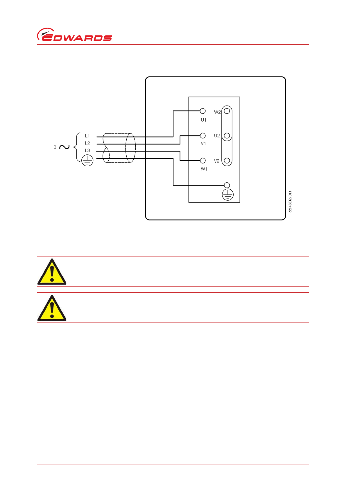
Wire colour codes:
BN Brown VT Violet
GY Grey WH White
OR Orange
Figure 3 - Electrical supply connection: single-phase motors: 220-240 V 50 Hz and 230-240 V 60 Hz
Installation
Figure 4 - Electrical supply connection: single-phase motors: 100 V 50 Hz, 100-105 V 60 Hz and 115 V 60 Hz
© Edwards Limited 2011. All rights reserved. Page 15
Edwards and the Edwards logo are trademarks of Edwards Limited.
Page 22

A343-10-880 Issue P
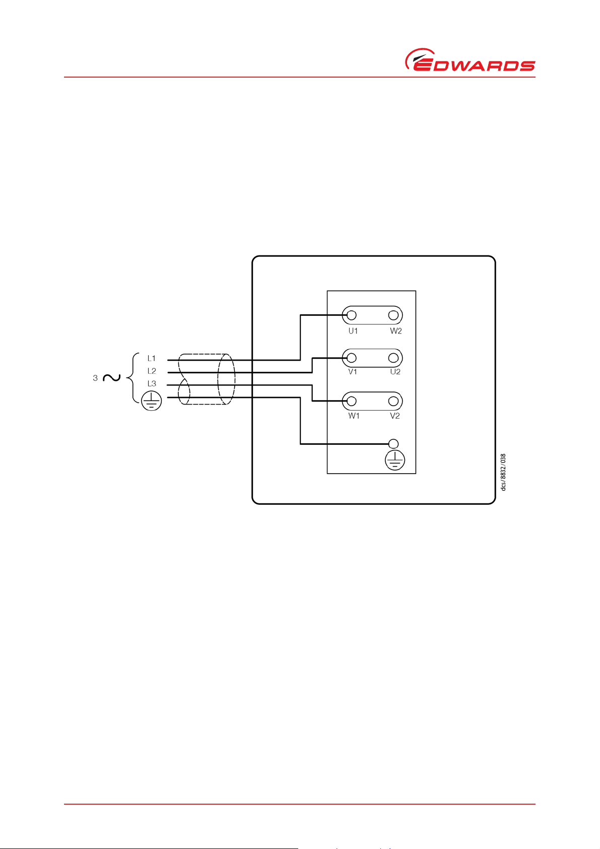
Wire colour codes:
BN Brown VT Violet
GY Grey WH White
OR Orange
Installation
Figure 5 - Electrical supply connection, single-phase motors: 200 V 50 Hz, 200-210 V 60 Hz and 230 V 60 Hz
Page 16 © Edwards Limited 2011. All rights reserved.
Edwards and the Edwards logo are trademarks of Edwards Limited.
Page 23

A343-10-880 Issue P
Pin codes:
1Live
2 Neutral
3Not used
Earth (ground)
Figure 6 - Electrical supply connection, single-phase motors with Amphenol connector:
220-240 V 50 Hz and 230-240 V 60 Hz
Installation
© Edwards Limited 2011. All rights reserved. Page 17
Edwards and the Edwards logo are trademarks of Edwards Limited.
Page 24

A343-10-880 Issue P
CAUTION
WARNING
A. Top view of motor
B. Internal view of top of motor
C. Voltage selector switch
1. Terminal box cover
2. Electrical inlet socket
3. On/Off switch
4. Position 'I' (on)
5. Position 'O' (off)
6. Voltage selector switch
7. Position 'II' (high voltage setting 200 – 240 V)
8. Position 'I' (low voltage setting 110 – 120 V)
Installation
Figure 7 - Motor voltage selection: single-phase motors, 110/200-240 V 50 Hz and 115-120/200-240 V 60 Hz
3.7 Electrical installation: three-phase motors
3.7.1 Connect the electrical supply to the motor
Ensure that the electrical installation of the pump conforms with your local and national safety
requirements. It must be connected to a suitably fused and protected electrical supply and a
suitable earth (ground) point.
Ensure that the motor is correctly configured for your electrical supply voltage and frequency. If you do not,
you can damage the motor.
Note: The pump will restart automatically when the electrical supply is restored after an interruption. If you do
Page 18 © Edwards Limited 2011. All rights reserved.
not want the pump to restart automatically, use electrical control equipment which must be reset
manually.
Edwards and the Edwards logo are trademarks of Edwards Limited.
Page 25

A343-10-880 Issue P
CAUTION
We recommend that you connect the electrical supply to the motor through a starter or circuit breaker which has
thermal over-current protection which can be adjusted to suit the full load current ratings shown in Table 5. The fuse
ratings in Table 5 are provided for guidance only. The supplier of your thermal overcurrent protection de vice may
specify different values to ensure correct operation of the fuse and the overcurrent protection device. Ensure that
the fuse you use is suitable for the starting currents given in Table 5. Refer to Figure 8 or 9 as appropriate for the
correct electrical supply connection diagram for your motor.
The diameter of the outer sheath of the electrical cable must be in the range 10-14 mm. The cable must conform in
size and colour coding with your local and national electrical installation regulations. The temperature rating of the
cable must be 70 °C or greater.
1. Remove the cover from the motor terminal-box.
2. Remove the cable- gland from the inside of the terminal-box and fit the cable-gland to the cable leadthrough
hole in the side of the terminal-box.
3. Refer to the electrical supply conn ection di agram for you r pump, (Figure 8 or 9). Make sure that the metal links
are connected as shown; if they are not, move the links to the positions shown.
4. Pass the electrica l supply cable through the cable-gland and connect to the appropriate terminals, as shown in
Figure 8 and 9. You must tighten the earth (ground) terminal connection to a torque of 2.13 to 2.87 Nm.
5. Tighten the cable gland until the outer sheath of the cable is firmly gripped. Do not overtighten.
6. Ensure that the gasket seal for the terminal box cover is correctly positioned, then refit the cover to the
terminal-box and secure with the screws.
Installation
3.7.2 Check the direction of rotation
Ensure that the motor rotates in the correct direction. If it does not, the pump and your vacuum system can
become pressurized when you operate the pump.
1. With the pump inlet still unconnected, watch the motor cooling-fan through the motor fan-cover, switch-on the
electrical supply to the motor for a few seconds, then switch off the electrical supply again.
2. Check that the motor cooling-fan rotates in the correct direction shown by the arrow on the motor mounting
plate. If the direction of rotation is incorrect:
z Switch off the electrical supply immediately.
z Isolate the pump from the electrical supply.
z Remove the terminal-box cover and swap wires L1 and L3: refer to Figure 8 and 9.
z Refit the cover to the terminal-box.
3.8 Connect the pump inlet
Take note of the following information when you connect the pump to your vacuum system. Re fer to Section 7.4 for
details of the accessories mentioned below.
z For optimum pumping speeds, ensure that the pipeline connected to the inlet-port is as short as possible and
has an internal diameter not less than the inlet-port diameter.
z Suppo rt the vacuum pipelines to prevent loading of the coupling-joints.
z If necessary, incorporate flexible bellows in your system pipelines to reduce the transmission of vibration and
to prevent loading of coupling-joints. If you use flexible bellows, you must ensure that you use bellows which
have a maximum pressure rating which is greater than the highest pressure that can be generated in your
system. We recommend that you use Edwards flexible bellows.
© Edwards Limited 2011. All rights reserved. Page 19
Edwards and the Edwards logo are trademarks of Edwards Limited.
Page 26
A343-10-880 Issue P
Installation
z Use a suitab le inlet catchpot if you pump condensable vapours or if you use the pump for very dusty
applications.
z Ensure t hat sealing surfaces are clean and scratch-free.
Connect your vacuum system to the inlet-port (Figure 1, item 6). To make this connection, you can:
z Connect to the N W25 flange supplied: use the NW25 centring-ring and O-ring supplied.
z Remove the NW25 flange and connect to the 1 inch BSP threaded hole.
z Use an NW25 to 28 mm bore tube adaptor a vailable as an optional accessory, refer to Section 7.4.11.
Figure 8 - Electrical supply connection, three-phase motors: 200-220 V 50 Hz and 200-230 V 60 Hz
Page 20 © Edwards Limited 2011. All rights reserved.
Edwards and the Edwards logo are trademarks of Edwards Limited.
Page 27
A343-10-880 Issue P
WARNING
WARNING
Figure 9 - Electrical supply connection, three-phase motors: 380-415 V 50 Hz and 460 V 60 Hz
Installation
3.9 Connect the pump outlet
Connect the pump outlet to a suitable treatment plant to prevent the discharge of dangerous gases
and vapours to the surrounding atmosphere.
Use a catchpot to prevent the drainage of contaminated condensate back into the pump.
The exhaust system must be configured so that the maximum pressure at the pump outlet does not exceed 0.5 bar
gauge (1.5 bar absolute, 1.5 x 10
We recommend that you fit an oil mist filter to the pump outlet in the following circumstances:
z If you use the pump with the gas-ballast control open.
z If you operate the pump w ith an inlet pressure greater than 10 mbar for extended periods.
z If you frequently pump down from atmospheric pressure.
The mist filter will trap the oil exhausted from the pump: you can reuse the oil if it is not contaminated.
To connect the pump to your outlet accessories or to your exhaust treatment plant, you can:
5
Pa) at full pump throughput.
z Connect 15 mm internal diameter vacuum or plastic hose to the outlet nozzle (Figure 1, item 2).
z Remove the outlet nozzle and connect to the 3/4 inch BSP threaded hole.
z Remove the outlet nozzle and replace it with an NW25 flange adaptor (available as an optional accessory,
refer to Section 7.4.13) and then connect to the NW25 flange.
© Edwards Limited 2011. All rights reserved. Page 21
Edwards and the Edwards logo are trademarks of Edwards Limited.
Page 28

A343-10-880 Issue P
Installation
3.10 Gas-ballast inlet connection
The position of the gas-ballast inlet is shown in Figure 1 (item 4). The gas-ballast inlet has several filters (shown in
Figure 11) to trap any dust and debris if you use air as the gas-ballast supply.
If you want to use a different gas for the gas-ballast supply, or if you want to connect a valve to the gas-ballast inlet:
1. Remove the filters (as described in Section 5.6).
2. Connect your gas supply or valve to the 1/4 in ch BSP threaded hole.
3.11 Leak test the system
Leak-test the system and seal any leaks found after you have installed the pump, to prevent leakage of substances
out of the system and leakage of air into the system.
Page 22 © Edwards Limited 2011. All rights reserved.
Edwards and the Edwards logo are trademarks of Edwards Limited.
Page 29

A343-10-880 Issue P
WARNING
WARNING
4 Operation
Do not expose any part of your body to vacuum. If you do, you may be injured.
Note: If your pump is PFPE-prepared, refer to Section 8.
4.1 ATEX directive implications
4.1.1 Introduction
This equipment is designed to meet the requirements of Group II Category 3 equipment in accordance with Directive
94/9/EC of the European Parliament and the Council of 23rd March 1994 on the approximation of the laws of the
Member States concerning equipment and protective systems intended for use in potentially explosive atmospheres.
(The ATEX Directive)
The ATEX Category 3 applies in respect of potential ignition sources internal to the equipment. An ATEX Category has
not been assigned in respect of potential ignition sources on the outside of the equipment as the equipment has not
been designed for use where there is an external potentially explosive atmosphere.
Operation
There is no potential source of ignition within the pump during normal operation but there may be potential sources
of ignition under conditions of predictable and rare malfunction as defined in the Directive. Accordingly, although
the pump is designed to pump flammable materials and mixtures, operating pr ocedures should ensure that under all
normal and reasonably predictable conditions, these materia ls and mixtures are not within explosive limits. Category
3 is considered appropriate for the avoidance of ignition in the case of a rare malfunction which allows flammable
materials or mixtures to pass through the pump whilst within their explosive limits.
4.1.2 Flammable/pyrophoric materials
You must obey the instructions and take note of the precautions given below, to ensure that
pumped gases do not enter their flammable ranges.
When flammable or pyrophoric materials are present within the equipment you must:
z Not allow air to enter the equipment.
z Ensure that the system is leak tight.
z Use an in ert gas purge (for example, a n itrogen purge) to dilute any flammable gases or vapours entering the
pump inlet, and/or use an inert gas purge to reduce the concentration of flammable gases or vapours in the
pump and in the exhaust pipeline to less than one quarter of the gases' published lower explosive limits
(LEL).
z Use an inert gas purge into the pump gas ballast connection to prevent the condensation of flammable
vapours within the pump mechanism and exhaust pipeline.
© Edwards Limited 2011. All rights reserved. Page 23
Edwards and the Edwards logo are trademarks of Edwards Limited.
Page 30

A343-10-880 Issue P
WARNING
WARNING
Operation
4.1.3 Gas purges
If you use inert gas purges to dilute dangerous gases to a safe level, ensure that the pump is shut
down if an inert gas supply fails.
You must obey the instructions and take note of the precautions given below, to ensure that
pumped gases do not enter their flammable ranges.
Switch on the inert gas purge to remove air from the pump and the exhaust pipeline before the process starts. Switch
off the purge flow at the end of the process only after an y remaining flammable gases or vapours have been purged
from the pump and exhaust pipeline.
If liquids that produce flammable vapours could be present in the pump foreline, then the inert gas purge to the
pump should be left on all the time this liquid is present. Flammable liquids could be present in the foreline as a
result of condensation, or may be carried over from the process.
When you calculate the flow rate of inert gas required for dilution, consider the maximum flow rate for the
flammable gases/vapours that could occur. For example, if a ma ss flow controller is used to supply flammable gases
to the process, you should assume a flow rate for flammable gases that could arise if the mass flow controller is fully
open.
Continually measure the inert gas purge flow rate: if the flow rate falls below that required, you must stop the flow
of flammable gases or vapours into the pump.
Note: We recommend that you obtain and read the Vacuum Pump and Vacuum System Safety manual (publication
number P300-20-000), available from Edwards or your supplier.
4.2 Gas-ballast control
Use the gas-ballast control (Figure 1, item 3) to change the flow of gas-ballast into the low vacuum stage of the pump,
and to provide an additional oil-feed to the pump mechanism.
Use the gas-ballast control closed:
z To achieve ultimate vacuum.
z To pump dry gases.
Turn the gas-ballast control by up to two turns anti-clockwise to introduce an additional oil-feed to the pump
mechanism. We recommend that you do this when you pump high throughputs of dry gases.
Turn the gas-ballast control from two to six turns anti-clockwise to increase the gas-ballast from zero flow. Use gasballast flow:
z To pump high concentrations of condensable vapour.
z To decontaminate the oil.
When you operate the pump with the gas-ballast control open, there will be an increased rate of oil loss from the
pump. Ideally, a mist filter and oil return kit should be u sed on clean applications.
Page 24 © Edwards Limited 2011. All rights reserved.
Edwards and the Edwards logo are trademarks of Edwards Limited.
Page 31

A343-10-880 Issue P
WARNING
4.3 Start-up
Do not block the pump outlet or allow the outlet pressure to rise above 1.5 bar absolute. If you do,
the oil box may fracture and may cause injury to people nearby.
If the oil is contaminated, or if the pump temperature is below 13 °C, or if the electrical su pply voltage is more than
10% below the lowest voltage specified for the pump, the pump may operate at a reduced s peed for a few minutes.
On single-phase pumps, if the pump continues to operate at reduced speed, the motor thermal overload device w ill
open and stop the pump. When the motor has cooled, the thermal overload device will reset automatically and the
pump will restart.
1. Check that the pump oil-level is between the MAX and MIN marks on the bezel of the oil-level sight-glass; if it is
not, refer to Section 5.3.
2. Turn the gas-ballast control to the required position (refer to Section 4.2).
3. Switch on the electrical supply to the pump.
4. Check that the oil-level in the sight-glass drops slightly (by 3 to 5 mm) after start-up. This shows that the pump
has primed with oil.
Operation
5. If the pump fails to prime, operate the pump with the inlet open to atmosphere for approximately 30 seconds.
Then isolate the inlet and check that the oil-level drops by 3 to 5 mm.
6. If you want to achieve ultimate vacuum, to pump condensable vapours or to decontaminate the pump oil, refer
to the procedures in Section 4.4, 4.5 and 4.6 respectively. Otherwise, open the vacuum system isolation-valve.
4.4 To achieve ultimate vacuum
If the pump does not achieve the performance specified in Section 2.2, make sure that this is not due to your system
design before you contact your supplier or Edwards for advice, In pa rticular, the vapour pressure of all mate rials used
in your vacuum system (including pump oil, refer to below) must be much lower than the specified ultimate vacuum
of the pump.
Refer to Section 5.11.3 for a list of possible causes for failure to achieve the specified performance; note however
that the most common causes are:
z Your pressure measurement technique or gauge head is unsuitable or the gauge head is faulty.
z You have used an oil other than the recommended oil, and the vapour pressure of the oil is higher than the
specified ultimate vacuum of the pump.
Use the following procedure to achieve ultimate vacuum:
1. Isolate the pump from your vacuum system.
2. Turn the gas-ballast control fully anti-clockwise (fully open) and operate the pump for at least 1 hour (or
overnight) to thoroughly purge the oil of contaminants.
3. Close the gas-ballast control.
4. Open the vacuum system isolation-valve and pump down to ultimate vacuum.
© Edwards Limited 2011. All rights reserved. Page 25
Edwards and the Edwards logo are trademarks of Edwards Limited.
Page 32

A343-10-880 Issue P
Operation
4.5 To pump condensable vapours
Use gas-ballast (open the gas-ballast control) when there is a high proportion of condensable vapours in the process
gases:
1. Close the vacuum system isolation-valve.
2. Turn the gas-ballast control anti-clockwise to fully open and operate the pump for 30 minutes to warm the oil;
this will help to prevent vapour condensation in the pump.
3. Open the vacuum system isolation-valve and continue to operate the pump with the gas-ballast control open.
After you have pumped condensable vapours, you can (if necessary) decontaminate the oil; use the procedure in
Section 4.6.
4.6 To decontaminate the oil
The oil in the pump should be clear, if the oil is cloudy or discoloured, it is contaminated with process vapours.
1. Look at the condition of the oil in the oil sight-glass (Figure 1, item 12). If the oil is cloudy or discoloured,
continue with the procedure at Step 2 below.
2. Close the vacuum system isolation-valve.
3. Turn the gas-ballast control fully anti-clockwise.
4. Operate the pump until the oil is clear.
4.7 Unattended operation
The pump is designed for unattended operation under the normal operating conditions specified in Section 2.1.
However, we recommend that you check the pump at a regular interval of not more than 14 days; check the pump
more frequently if you pump high volumes of gas or if you operate the pump with the gas-ballast control open.
Single-phase motors are cooled by internal fans. These motors have a thermal overload device. When the motor is
too hot, the thermal overload device switches off the pump. The thermal overload device has an automatic reset;
when the motor cools down, the device resets and the motor will restart.
When you check the pump, make sure that the pump is not going through a repetitive cycle of thermal overload
failures and automatic resets. If necessary reduce the thermal load from the pumped gases, to prevent overheating
of the pump.
4.8 Shut-down
Note: If the gas-ballast control is open and the motor is switched off for any reason, the pump drive shaft may
rotate in the reverse direction, causing a system pressure rise. To prevent this, use a gas-ballast control
valve (refer to Section 7.4.15).
We recommend, as described in the procedure below, that you decontaminate the oil before you shut down the
pump; this will prevent damage to the pump by the contaminates in the oil.
1. Refer to Section 4.6 and decontaminate the oil, as required.
2. Close the vacuum system isolation-valve (if not already closed).
3. Close gas-ballast (that is, turn the gas-ballast control clockwise).
4. Switch off the electrical supply to the pump.
Page 26 © Edwards Limited 2011. All rights reserved.
Edwards and the Edwards logo are trademarks of Edwards Limited.
Page 33

A343-10-880 Issue P
CAUTION
WARNING
5Maintenance
5.1 Safety information
Obey the safety instructions given below and take note of appropriate precautions. If you do not,
you can cause injury to people and damage to equipment.
Never use hydrocarbon lubricants in a PFPE-prepared pump.
Note: If your pump is PFPE-prepared, refer to Section 8.
z A suitably trained and supervised technician must maintain the pump.
z Ensure that the maintenance technician is familiar with the safety procedures which relate to the pump-oil
and the products processed by the pumping-system.
Maintenance
z Allow the pump to cool to a safe temperature before you start maintenance work.
z Isolate the pump and other components in the pumping system from the electrical supply so that they can
not be operated accidentally.
z After maintena nce is completed, recheck the pump rotation direction if the electrical supply has been
disconnected.
z Do not reuse O-rings and seals if they are damaged.
z The pump and its oil will be contaminated with the process chemicals that have been pumped during
operation. Ensure that the pump is decontaminated before maintenance and that you take adequate
precautions to protect people from the effects of dangerous substances if contamination has occurred.
z Leak-test the system after maintenan ce work is complete if you have conne cted or disconnected any vacuum
or exhaust joints; seal any leaks found.
z Do not touch or i nhale the thermal breakdown products of fluorinate d materials which may be present if the
pump has been heated to 260 °C and above. These breakdown products are very dangerous. Fluorinated
materials in the pump may include oils, greases and seals. The pump may have overheated if it was misused,
if it malfunctioned or if it was in a fire. Edwards Material Safety Data sheets for fluorinated materials used in
the pump are available on request: contact your supplier or Edwards.
5.2 Maintenance plan
The plan shown in Table 9 details the routine maintenance operations necessary to maintain the pump in normal use.
Instructions for each operation are given in the section shown.
More frequent maintenance may be required if the pump is used to proces s corrosive or abrasive gase s and vapours;
in these circumstances, we recommend that you replace the pump seals every year. If necessary, adjust the
maintenance plan according to your experience.
When you maintain the pump, use Edwards spares and maintenance kits; th ese contain all of the components
necessary to complete maintenance operations successfully. The Item Numbers of the spares and kits are given in
Section 7.3.
Examine the condition of any external accessories, filters or traps (if fitted) when you ma intai n the pump. Re fer to
the instructions supplied with these accessories for the necessary maintenance procedures.
© Edwards Limited 2011. All rights reserved. Page 27
Edwards and the Edwards logo are trademarks of Edwards Limited.
Page 34

A343-10-880 Issue P
Maintenance
Table 9 - Maintenance plan
Operation Frequency
Check the oil level As required; at least monthly 5.3
Replace the oil Every 3000 hours of operation 5.4
Inspect and clean the inlet filter Every oil change 5.5
Clean or replace the gas-ballast filter Yearly 5.6
Clean the motor fan-cover and enclosure Yearly 5.7
Clean and overhaul the pump Every 15000 hours of operation 5.8
Replace the run capacitor Every 30000 hours of operation 5.9
Test the motor condition Every 15000 hours of operation 5.9
Fit new blades Every 30000 hours of operation 5.10
Refer to
Section
5.3 Check the oil-level
Notes: 1. If required, you can check the oil-level while the pump is operating, however you must switch off the
pump and isolate the pump and other components in the pumping system from the electrical supply
before you pour oil into the pump.
2. Do not mix hydrocarbon lubricants with PFPE or vice versa. If the oil is mixed, drain and refill with clean
oil as described in Section 5.4.
Refer to Figure 1 for the items in brackets.
1. Check that the oil-level in the oil sight-glass (12) i s between the MAX and MIN le vel mark s on the bezel of the oi l
sight-glass.
2. If the oil-level is near to or below the MIN level mark, remove the oil filler-plug (1) and pour more oil into the
reservoir until the oil reaches the MAX level mark. If the oil-level goes above the MAX mark, remove the oil
drain-plug (11) and drain the excess oil from the pump. Refit the oil drain-plug. Refit the oil filler-plug.
3. If the oil is contaminated, drain and refill the pump with clean oil as described in Section 5.4.
5.4 Replace the oil
Refer to Figure 1 for the items in brackets.
1. Operate the pump for approximately ten minutes to warm the oil, then switch off the pump. (This lowers the
viscosity of the oil and allows the oil to be drained from the pump more easily).
2. Isolate the pump from your electrical supply and disconnect it from your vacuum system.
3. Remove the oil filler-plug (1).
4. Place a suitable block under the pump-motor to tilt the pu mp an d place a suitable contai ner under the oi l drainplug (gravity drain) (11). Remove the oil drain-plug and allow the oil to drain into the container.
5. If the oil is dirty or contaminated:
z Refit the oil drain-plug and pour clean oil into the pump.
z Reconnect the pump to the electrical supply and operate the pump for about 5 to 10 minutes.
z Disconnect the pump from the electrical supply, remove the oil drain-plug and allow the oil to drain out of
the pump.
z Repeat this step until the oil reservoir is clean.
6. Refit the oil drain- plug, remove the block and reconnect the pump to your vacuum system.
Page 28 © Edwards Limited 2011. All rights reserved.
Edwards and the Edwards logo are trademarks of Edwards Limited.
Page 35

A343-10-880 Issue P
1. Inlet adaptor
2. O-ring
3. Circlip
4. Inlet-filter
7. Fill a suitable container with clean oil and pour the oil into the filler hole until the oil-level reaches the MAX
level mark on the bezel of the oil sight-glass (12).
8. Allow a few minutes for the oil to drain into the pump. If necessary, add more oil. Refit the oil filler-plug.
5.5 Inspect and clean the inlet-filter
Refer to Figure 10.
1. Unscrew the inlet adaptor (1) and remove the O-ring (2), circlip (3) and inlet-filter (4).
2. W ash the filter in a suitable cleaning solution. Allow the filter to dry.
3. Refit the inlet-filter (4), circlip (3), O-ring (2) and inlet adaptor (1).
Figure 10 - Remove/replace the inlet filter
Maintenance
© Edwards Limited 2011. All rights reserved. Page 29
Edwards and the Edwards logo are trademarks of Edwards Limited.
Page 36

A343-10-880 Issue P
1. Filter element
2. Wire mesh
3. Retainer circlip
Maintenance
5.6 Clean the gas-ballast filter
Note: You may have removed the gas-ballast filter to connect a gas supply or valve to the gas-ballast inlet.
Refer to Figure 11.
1. Remove the retainer circlip (3).
2. Remove the protective wire mesh (2) and filter elements (1).
3. Wash the wire mesh and filter in a suitable cleaning solution. Allow the wire mesh and filter to dry before
replacing them in the pump.
4. Refit the wire mesh (2) and filter element (1) in the adaptor plate housing and retain with the retainer circlip
(3).
Figure 11 - Remove/replace the gas-ballast filter
5.7 Clean the motor fan-cover and enclosure
If the motor fan-cover and enclosure are not kept clean, the air-flow over the motor can be restricted and the pump
may overheat.
1. Switch off the pump and disconnect it from the electrical supply.
2. Use a dry cloth and a brush to remove dirt and deposits from the fan-cover and enclosure.
5.8 Clean and overhaul the pump
Clean and overhaul the pump as described in the instructions supplied with the clean and overhaul kit (refer to
Section 7.3).
Page 30 © Edwards Limited 2011. All rights reserved.
Edwards and the Edwards logo are trademarks of Edwards Limited.
Page 37

A343-10-880 Issue P
5.9 Replace the run capacitor and test the motor
Replace the run capacitor as described in the instructions supplied with the capacitor kit.
Test the earth (ground) continuity and the insulation resistance of the pump-motor, in accordance with local
regulations for periodic testing of electrical equipment. We recommend that:
z The earth (ground) continuity is less than 0.1 Ω.
z Insulation resistance is greater than 10 MΩ.
If the motor fails these tests, you must replace the motor.
5.10 Fit new blades
Fit new blades to the pump as described in the instructions supplied with the blade kit (refer to Section 7.3).
5.11 Fault finding
5.11.1 Introduction
Maintenance
A list of fault conditions and their possible causes is provided in the following sections to assist you in basic faultfinding. If you are unable to rectify a fault when you use this guide, call your supplier or your nearest Edwards Service
Centre for advice.
5.11.2 The pump has failed to start
z The electrical supply fuse has failed.
z The motor is incorrectly wired.
z The operating voltage does not match that of the motor.
z The exhaust filter or exhaust line is blocked.
z The oil temp erature is below 13 °C.
z The oil is too viscous.
z The oil is contaminated.
z The pump is seized after long storage, or has been left to stand after pumping contaminants.
z The motor is faulty.
© Edwards Limited 2011. All rights reserved. Page 31
Edwards and the Edwards logo are trademarks of Edwards Limited.
Page 38

A343-10-880 Issue P
Maintenance
5.11.3 The pump fail to achieve specified performance (failure to reach ultimate
vacuum)
z Your measuring technique or gauge is unsuitable.
z There is a leak in the external vacuum system.
z The gas-ballast control is open.
z The oil level is too low.
z You have filled the pump with the wrong type of oil.
z The oil is contaminated.
z The pump has not primed.
z The vacuum fittings are dirty.
z The inlet-filter is blocked.
z The pump has not warmed up.
z The mot or shaft rotates in the wrong direction.
5.11.4 The pump is noisy
z The motor fan-cover is damaged.
z The coupling and fan assembly are poorly adjusted.
z The motor coupling is loose .
z The motor bearings are worn.
z The oil is contaminated with solid particles.
z One of the pump blad es is sticking.
5.11.5 The pump surface temperature is above 100 °C
z The ambient temperature is too high.
z The cooling-air supply is ins ufficient or is too hot.
z The cooling-air supply is blocked.
z The electrical supply voltage is too high.
z The exhaust filter or exhaust line is blocked.
z The oil level is too low.
z The pump is filled with the wrong type of oil.
z The oil is contaminated.
z The process gas is too hot, or the throughput is too high.
Page 32 © Edwards Limited 2011. All rights reserved.
Edwards and the Edwards logo are trademarks of Edwards Limited.
Page 39

5.11.6 The vacuum is not maintained after the pump is switched off
z The gas-ballast control is open.
z O-ring(s) are damaged or missing.
z The shaft seals have deteriorated.
5.11.7 The pumping speed is poor
z The connecting pipelines are too small in diameter.
z The connecting pipelines are too long.
z The inlet-filter is blocked.
5.11.8 There is an external oil leak
z The oil pu mp shaft seal is worn or damaged.
z The oil box gasket has deteriorated.
z There is an oil leak from gas-ballast control.
A343-10-880 Issue P
Maintenance
z There is an oil-leak from the drain-plug.
© Edwards Limited 2011. All rights reserved. Page 33
Edwards and the Edwards logo are trademarks of Edwards Limited.
Page 40

A343-10-880 Issue P
This page has been intentionally left blank.
Page 34 © Edwards Limited 2011. All rights reserved.
Edwards and the Edwards logo are trademarks of Edwards Limited.
Page 41

A343-10-880 Issue P
CAUTION
6 Storage and disposal
6.1 Storage
Observe the storage temperature limits stated in Section 2.1. Storage below these limits will permanently
damage the pump seals.
Note: If you will store a new pump in conditions of high humidity, remove the pump from its cardboard packaging
box; dispose of the box (refer to Section 6.2).
Use the following procedure to store the pump:
1. Shut-down the pump as described in Section 4.8.
2. Disconnect the pump from the electrical supply.
3. Purge your vacuum system and the pump with dry nitrogen and disconnect the pump from your vacuum system.
4. Replace the oil as described in Section 5.4.
Storage and disposal
5. Place and secure protective covers over the inlet and outlet-ports.
6. Store the pump in cool, dry conditions until required for use.
When required, prepare and install the pump as described in Section 3. If the pump has been stored for more than a
year, you must clean and overhaul the pump before you install it, as de scribed i n the ins tructions supp lied wi th the
clean and overhaul kit.
6.2 Disposal
Dispose of the pump, the oil and any components removed from the pump safely in accordance with all local and
national safety and environmental requirements.
Particular care must be taken with components and waste oil which have been contaminated with dangerous process
substances.
Do not incinerate fluoroelastomer seals and O-rings.
© Edwards Limited 2011. All rights reserved. Page 35
Edwards and the Edwards logo are trademarks of Edwards Limited.
Page 42

A343-10-880 Issue P
This page has been intentionally left blank.
Page 36 © Edwards Limited 2011. All rights reserved.
Edwards and the Edwards logo are trademarks of Edwards Limited.
Page 43

A343-10-880 Issue P
7 Service, spares and accessories
7.1 Introduction
Edwards products, spares and accessories are available from Edwards companies in Belgium, Brazil, China, France,
Germany, Israel, Italy, Japan, Korea, Singapore, United Kingdom, U.S.A and a world-wide network of distributors.
The majority of these centres employ Service Engineers who have undergone comprehensive Edwards training
courses.
Order spare parts and accessories from your nearest Edwards company or distributor. When you order, state for each
part required:
z Model and Item Number of your equipment
z Serial number
z Item Number and description of part.
7.2 Service
Edwards products are supported by a world-wide network of Edwards Service Centres. Each Service Centre offers a
wide range of options including: equipment decontamination; service exchange; repair; rebuild and testing to factory
specifications. Equipment which has been serviced, repaired or rebuilt is returned with a full warranty.
Service, spares and accessories
Your local Service Centre can also provide Edwards engineers to support on-site maintenance, service or repair of
your equipment.
For more information about service options, contact your nearest Service Centre or other Edwards company.
7.3 Spares
The maintenance kits listed in Table 10 contain all of the parts you will need to maintain your pump. The
maintenance kits also include instructions for the use of the kits.
Use the Clean and Overhaul kit for routine maintenance operations. Use the Blade kit together with the Clean and
Overhaul kit when you must renew the blade assembly in the rotary pump.
Table 10 - Spares item numbers
Spare Item Number
Clean and Overhaul kit (Hydrocarbon filled) A363-01-131
Clean and Overhaul kit (PFPE filled) A363-01-136
E1M18 Blade kit A343-01-041
E2M18 Blade kit A363-01-020
Ultragrade 19 Oil (4 litres) H110-25-013
Fomblin Grade 06/6-500 ml H113-01-016
Capacitor kit for pump part number A343-15-903 A505-91-813
Capacitor kit for pump part number A343-16-903 A505-91-813
Capacitor kit for pump part number A363-15-903 A505-91-813
Capacitor kit for pump part number A343-15-904 A505-91-800
Capacitor kit for pump part number A363-15-904 A505-91-800
Capacitor kit for pump part number A363-25-904 A505-91-800
© Edwards Limited 2011. All rights reserved. Page 37
Edwards and the Edwards logo are trademarks of Edwards Limited.
Page 44

A343-10-880 Issue P
Service, spares and accessories
Table 10 - Spares item numbers (continued)
Spare Item Number
Capacitor kit for pump part number A343-15-912 A505-91-811
Capacitor kit for pump part number A363-15-912 A505-91-811
Capacitor kit for pump part number A363-25-912 A505-91-811
Capacitor kit for pump part number A343-15-920 A505-91-812
Capacitor kit for pump part number A363-15-920 A505-91-812
Capacitor kit for pump part number A343-15-981 A505-91-800
Capacitor kit for pump part number A363-15-981 A505-91-800
Capacitor kit for pump part number A343-17-984 A505-91-814
Capacitor kit for pump part number A343-25-984 A505-91-814
Capacitor kit for pump part number A363-17-984 A505-91-814
Capacitor kit for pump part number A363-25-984 A505-91-814
7.4 Accessories
7.4.1 Introduction
A range of accessories is available for the E1M18 and E2M18 pumps, as shown in Figure 12.
The accessories are briefly described in the following sections. Refer to Table 11 for the Item Numbers of these
accessories.
Table 11 - Accessory item numbers
Accessory Item Number
ITO20K Inlet Catchpot A441-10-000
ITF20K Inlet Dust Filter A442-15-000
ITD20K Inlet Desiccant Trap A445-10-000
ITC20K Inlet Chemical Trap A444-10-000
EMF20 Outlet Mist Filter A462-29-000
PV25EK Valve: 200/240 V, 1-phase, 50/60 Hz C413-01-000
PV25EK Valve: 110/127 V, 1-phase, 50/60 Hz C413-03-000
FL20K Foreline Trap A133-05-000
Vibration Isolators (pack of four) A248-01-412
ODE 1/4 Oil Drain Extension A505-03-000
Pump Inlet Adaptor C105-20-201
Flexible Bellows C105-14-670
Pump Outlet Adaptor C105-01-414
Gas Ballast Banjo Elbow Assembly A500-06-003
Gas Ballast Valve: 110 V, 50/60 Hz A500-06-984
Gas Ballast Valve: 240 V, 50/60 Hz A500-06-930
7.4.2 Inlet catchpot
The Inlet Catchpot traps any liquid droplets and prevents their entry into the pump.
Page 38 © Edwards Limited 2011. All rights reserved.
Edwards and the Edwards logo are trademarks of Edwards Limited.
Page 45

A343-10-880 Issue P
7.4.3 Inlet dust filter
The Inlet Dust Filter protects the pump against abrasive dust.
7.4.4 Inlet desiccant trap
Use a Desiccant Trap when you pump limited quantities of water vapour at high pumping speeds to a low vapour
pressure.
7.4.5 Inlet chemical trap
The Inlet Chemical Trap protects the pump against chemically active gases.
7.4.6 Outlet mist filter
The Outlet Mist Filter separates and traps oil drop lets in the pump outlet to prevent oil mist discharge. The Mist Filter
is supplied with an adaptor to connect it to the pump outlet.
Service, spares and accessories
© Edwards Limited 2011. All rights reserved. Page 39
Edwards and the Edwards logo are trademarks of Edwards Limited.
Page 46
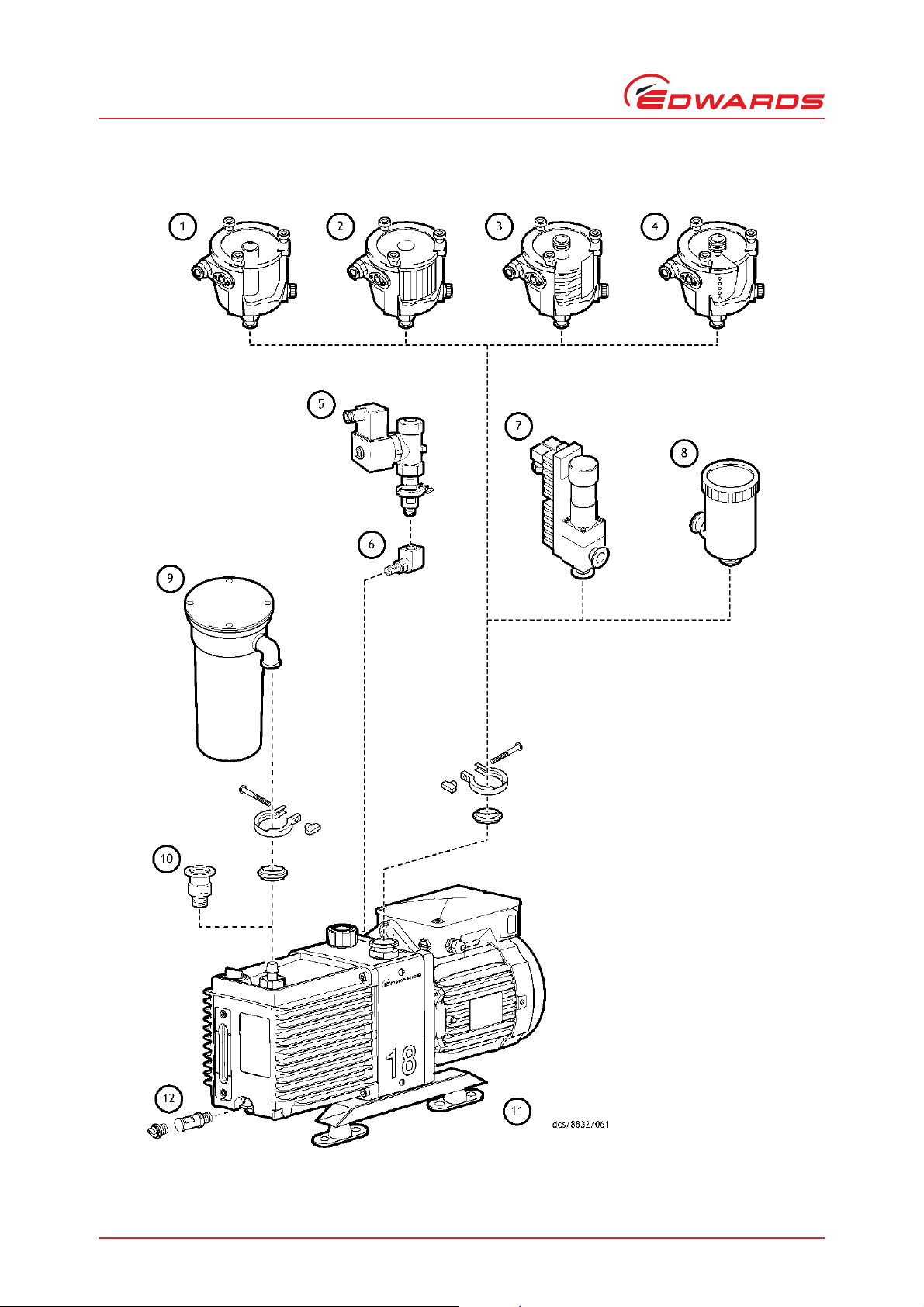
A343-10-880 Issue P
1. Inlet catchpot
2. Inlet dust filter
3. Inlet desiccant trap
4. Inlet chemical trap
5. Gas ballast valve
6. Banjo/elbow assembly
7. Solenoid operated pipeline valve
8. Foreline trap
9. Outlet mist filter
10.NW25 adaptor
11.Vibration isolators
12.Oil drain extension
Service, spares and accessories
Figure 12 - Accessories
Page 40 © Edwards Limited 2011. All rights reserved.
Edwards and the Edwards logo are trademarks of Edwards Limited.
Page 47

A343-10-880 Issue P
7.4.7 Solenoid operated pipeline valve
Fit the Pipeline Valve between your vacuum system and the pump inlet to provide additional system protection when
the pump is switched off.
7.4.8 Foreline trap
Use a Foreline Trap on a clean pumping system to prevent back-migration of rotary pump oil vapour into your vacuum
system.
7.4.9 Vibration isolators
The Vibration Isolators reduce transmission vibration and noise when the pump is floor or frame mounted and help
to reduce strain when the mounting area is uneven.
7.4.10 Oil drain extension
Fit the Oil Drain Extension between the oil drain port on the pump and the oil drain-plug to make the drainage of oil
from the pump easier.
Service, spares and accessories
7.4.11 Pump inlet adaptor
This is an NW25 to 28 mm bore tube adaptor, supplied with connection hardware. Attach this adaptor to the NW25
pump-inlet to connect 28 mm bore plastic or rubber tube.
7.4.12 Flexible bellows
Use Flexible Bellows to connect the pump-inlet to your vacuum system. We recommend that you use bellows when
you use Vibration Isolators.
7.4.13 Pump outlet adaptor
This is a 3/4 inch BSP to NW25 adaptor. Use this adaptor when you remove th e hose adaptor supplied fitted to the
pump outlet to adapt the 3/4 inch BSP thread to NW25 pump inlet.
7.4.14 Gas ballast banjo/elbow assembly
Use this 3/4 inch BSP assembly when a remote ballast supply, or gas ballast valve, is fitted.
7.4.15 Gas ballast valve
Use this to control the gas-ballast remotely. You will also need the Gas Ballast Banjo/Elbow Assembly (refer to
Section 7.4.14) when you fit this accessory.
© Edwards Limited 2011. All rights reserved. Page 41
Edwards and the Edwards logo are trademarks of Edwards Limited.
Page 48

A343-10-880 Issue P
This page has been intentionally left blank.
Page 42 © Edwards Limited 2011. All rights reserved.
Edwards and the Edwards logo are trademarks of Edwards Limited.
Page 49

A343-10-880 Issue P
CAUTION
WARNING
WARNING
8 PFPE-prepared EM pumps
8.1 Summary
If you have ordered a PFPE-prepared EM pump, the pump will be supplied prepared for use with Edwards PFPE
mechanical pump oils, such as Fomblin YVAC 06/6 and Krytox 1506.
PFPE-prepared EM pumps are suitable for pumping high concentrations of oxygen.
We recommend that you refer to Edwards publication P300-20-000 (Vacuum pump and Vacuum System Safety) before
you install and use a PFPE-prepared EM pump.
8.2 Installation
Never use hydrocarbon lubricants in a PFPE-prepared pump.
Installation of a PFPE-prepared EM pump is as specified in Section 3, but take note of the caution above.
PFPE-prepared EM pumps
8.3 Operation
PFPE-prepared EM pumps are suitable for pumping high concentrations of oxygen, but we
recommend that you do not use a PFPE-prepared EM pump for the pumping of hazardous materials.
Operation of a PFPE-prepared EM pump is as specified in Section 4, but take note of the warning above.
8.4 Maintenance
Obey the safety instructions given below and take note of appropriate precautions. If you do not,
you can cause injury to people.
z Take additional care if you suspect that the pump (and hence the PFPE oil) has overheated.
z Do not touch or inhale the thermal breakdown products of PFPE oil, which may be present, if the pump has
been heated to 260 °C and above. PFPE oils are safe in normal use but can decompose into very dangerous
substances if they are heated to 260 °C and above. The pump may have overheated if it was misused, if it
malfunctioned, or if it was in a fire. Material Safe ty Data Sheets for P FPE oils use d in the pu mp are availa ble
on request: contact your supplier or Edwards.
Fomblin oil has different properties from other pump oils, therefore:
z If you fill your PFPE-prepared EM pump with Fomblin oil, we recommend that you regularly check for oil
leaks, particularly around the shaft seals.
z If you detect an oil leak, contact your supplier or Edwards for advice.
© Edwards Limited 2011. All rights reserved. Page 43
Edwards and the Edwards logo are trademarks of Edwards Limited.
Page 50

A343-10-880 Issue P
This page has been intentionally left blank.
Page 44 © Edwards Limited 2011. All rights reserved.
Edwards and the Edwards logo are trademarks of Edwards Limited.
 Loading...