

Page 1

Instruction Manual
E2M0.7 and E2M1.5 Rotary Vacuum Pumps
A371–22–880
Issue R Original
Description Item Number
3 h-1
E2M0.7 (0.7 m
E2M0.7 (0.7 m
E2M1.5 (1.5 m
E2M1.5 (1.5 m3 h-1, 0.8 ft3 min-1) 220-240 V, 50/60 Hz (Interstage) A371-03-919
E2M1.5 (1.5 m3 h-1, 0.8 ft3 min-1) 100-120 V, 50/60 Hz A371-22-902
E2M1.5 (1.5 m
, 0.4 ft3 min-1) 220-240 V, 50/60 Hz A371-31-919
3 h-1
, 0.4 ft3 min-1) 100-120 V, 50/60 Hz A371-31-902
3 h-1
, 0.8 ft3 min-1) 220-240 V, 50/60 Hz A371-22-919
3 h-1
, 0.8 ft3 min-1) 100-120 V, 50/60 Hz (Interstage) A371-03-902
Page 2

Declaration of Conformity
We, Edwards Limited,
Crawley Business Quarter,
Manor Royal,
Crawley,
West Sussex, RH10 9LW, UK
declare under our sole responsibility, as manufacturer and person within the EU authorised
to assemble the technical file, that the product(s)
E2M0.7 and E2M1.5 Rotary Vacuum Pumps without IEC connector
A371-31-919 A371-22-919 A371-13-930 A371-31-902
A371-13-988 A371-22-902 A371-03-919
to which this declaration relates is in conformity with the following standard(s) or other
normative document(s)
EN61010-1:2010* Safety Requirements for Electrical Equipment for
Measurement, Control and Laboratory Use. General
Requirements
EN1012-2:1996+A1:2009 Compressors and Vacuum Pumps. Safety Requirements.
Vacuum Pumps
EN60034-1:2010 Rotating electrical machines. Rating and performance
CAN/CSA-C22.2 No 77:2014# Motors with inherent overheating protection
CAN/CSA-C22.2 No 100:2014# Motors and Generators
EN50581:2012 Technical Documentation for the Assessment of Electrical
and Electronic Products with respect to the Restriction of
Hazardous Substances
* 1-phase pumps only. The pumps comply with EN 61010-1 when installed in
accordance with the instruction manual supplied with the
#
100/120V pumps only. Canadian Standards Association.
pumps.
and fulfils all the relevant provisions of
2006/42/EC Machinery Directive
2014/35/EU Low Voltage Directive
2011/65/EU Restriction of Certain Hazardous Substances (RoHS)
Directive
Note: This declaration covers all product serial numbers from the date this Declaration was
signed onwards.
10.08.2015, Burgess Hill
Mr Peter Meares
Senior Technical Support Manager, General Vacuum
This product has been manufactured under a quality management system certified to ISO 9001:2008
Date and Place
P200-00-560 Issue E
Page 3

A371–22–880 Issue R
Contents
Section Page
1 Introduction .......................................................................................1
1.1 Scope and definitions ................................................................................................... 1
1.2 ATEX directive implications ............................................................................................ 2
1.3 Description ................................................................................................................ 4
1.4 Gas-ballast ................................................................................................................ 4
2 Technical data ....................................................................................5
2.1 Operating and storage conditions ..................................................................................... 5
2.2 Performance .............................................................................................................. 5
2.3 Mechanical data .......................................................................................................... 6
2.4 Electrical data ............................................................................................................ 6
2.5 Lubrication data ......................................................................................................... 7
3 Installation ............................................... ................................... .......9
3.1 Safety ......................................................................................................................9
3.2 System design ............................................................................................................ 9
3.3 Unpack and inspect .....................................................................................................10
3.4 Locate the pump ........................................................................................................10
3.5 Fill the pump with oil ..................................................................................................10
3.6 Electrical installation ..................................................................................................11
3.6.1 Connect the pump to your electrical supply .......................................................................11
3.6.2 Check the direction of rotation ......................................................................................11
3.7 Connect the pump inlet ................................................................................................12
3.7.1 General requirements ..................................................................................................12
3.7.2 Side inlet-port connection .............................................................................................13
3.8 Connect the pump outlet ..............................................................................................13
3.9 Leak-test the system ...................................................................................................13
Contents
4 Operation ........................................................................................ 15
4.1 ATEX directive implications ...........................................................................................15
4.1.1 Introduction .............................................................................................................15
4.1.2 Flammable/pyrophoric materials ....................................................................................15
4.1.3 Gas purges ...............................................................................................................16
4.2 Gas-ballast control .....................................................................................................16
4.3 Start-up procedure .....................................................................................................17
4.4 To achieve ultimate vacuum ..........................................................................................17
4.5 To pump condensable vapours ........................................................................................18
4.6 To decontaminate the oil ..............................................................................................18
4.7 Unattended operation ..................................................................................................18
4.8 Shut-down ................................................................................................................ 18
5 Maintenance ..................................................................................... 19
5.1 Safety information ......................................................................................................19
5.2 Maintenance plan .......................................................................................................19
5.3 Check the oil-level .....................................................................................................20
5.4 Replace the oil ..........................................................................................................20
5.5 Inspect and clean the inlet-filter .....................................................................................21
5.6 Clean or replace the gas-ballast O-ring .............................................................................21
5.7 Clean the motor fan-cover and enclosure ..........................................................................22
5.8 Clean and overhaul the pump .........................................................................................22
cg/8030/0813
© Edwards Limited 2013. All rights reserved. Page i
Edwards and the Edwards logo are trademarks of Edwards Limited.
Page 4

A371–22–880 Issue R
Contents
5.9 Fit new blades ...........................................................................................................22
5.10 Replace the capacitor and test the motor ..........................................................................22
5.11 Fault finding .............................................................................................................22
6 Storage and disposal ........................................................................... 25
6.1 Storage ...................................................................................................................25
6.2 Disposal ...................................................................................................................25
7 Service, spares and accessories .............................................................. 27
7.1 Introduction .............................................................................................................27
7.2 Service .................................................................................................................... 27
7.3 Spares .....................................................................................................................27
7.4 Accessories ...............................................................................................................28
7.4.1 Introduction .............................................................................................................28
7.4.2 Inlet catchpot ...........................................................................................................28
7.4.3 Inlet dust filter ..........................................................................................................28
7.4.4 Inlet desiccant trap .....................................................................................................28
7.4.5 Inlet chemical trap .....................................................................................................28
7.4.6 Foreline trap .............................................................................................................28
7.4.7 Outlet mist filter ........................................................................................................30
7.4.8 Oil drain extension .....................................................................................................30
7.4.9 Vibration isolators ......................................................................................................30
7.4.10 Pump inlet or outlet NW25 adaptor .................................................................................. 30
7.4.11 Solenoid operated gas-ballast control valve ........................................................................30
7.4.12 Solenoid operated pipeline valve ....................................................................................30
For return of equipment, complete the HS Forms at the end of this manual.
Illustrations
Figure Page
1 The E2M0.7 and E2M1.5 pump ......................................................................................... 3
2 Dimensions: mm (inches) ...............................................................................................7
3 Electrical supply connection ..........................................................................................12
4 Inlet-filter removal and replacement ...............................................................................21
5 Gas-ballast O-ring removal and replacement ......................................................................22
6 Accessories ...............................................................................................................29
Page ii © Edwards Limited 2013. All rights reserved.
Edwards and the Edwards logo are trademarks of Edwards Limited.
Page 5

A371–22–880 Issue R
Tables
Table Page
1 Operating and storage conditions ..................................................................................... 5
2 Performance data ........................................................................................................ 5
3 Mechanical data .......................................................................................................... 6
4 Electrical data ............................................................................................................ 6
5 Lubrication data ......................................................................................................... 7
6 Checklist of items .......................................................................................................10
7 Maintenance plan .......................................................................................................20
8 Fault finding .............................................................................................................23
9 Spares Item Numbers ...................................................................................................27
10 Accessories Item Numbers .............................................................................................28
Associated publications
Publication title Publication number
Contents
Vacuum Pump and Vacuum System Safety P400-40-100
© Edwards Limited 2013. All rights reserved. Page iii
Edwards and the Edwards logo are trademarks of Edwards Limited.
Page 6

A371–22–880 Issue R
This page has been intentionally left blank.
Page iv © Edwards Limited 2013. All rights reserved.
Edwards and the Edwards logo are trademarks of Edwards Limited.
Page 7
A371–22–880 Issue R
CAUTION
WARNING
1Introduction
1.1 Scope and definitions
This manual provides installation, operation and maintenance instructions for the Edwards E2M0.7, and E2M1.5 rotary
vacuum pumps. You must use the pump as specified in this manual. Read this manual before you install and ope rate
the pump.
Important safety information is highlighted as WARNING and CAUTION instructions; you must obey these instructions.
The use of WARNINGS and CAUTIONS is defined below.
Warnings are given where failure to observe the instruction could result in injury or death to
people.
Cautions are given where failure to observe the instruction could result in damage to the equipment, associated
equipment and process.
Introduction
The units used throughout this manual conform to the SI international sys tem of units of measurement. Equivalent
values using imperial units of measurement are also included.
The following warning symbols are on the pump:
Warning - refer to accompanying documentation.
Warning - risk of electric shock.
Warning - hot surfaces.
© Edwards Limited 2013. All rights reserved. Page 1
Edwards and the Edwards logo are trademarks of Edwards Limited.
Page 8

A371–22–880 Issue R
Introduction
1.2 ATEX directive implications
This equipment is designed to meet the requirements of Group II Category 3 equipment in accordance with Directive
94/9/EC of the European Parliament and the Council of 23rd March 1994 on the approximation of the laws of the
Member States concerning equipment and protective systems intended for use in potentially explosive atmospheres.
(The ATEX Directive)
The ATEX Category 3 applies in respect of potential ignition sources internal to the equipment. An ATEX Category has
not been assigned in respect of potential ignition sources on the outside of the equipment as the equipment has not
been designed for use where there is an external potentially explosive atmosphere.
There is no potential source of ignition within the pump during normal operation but there may be potential sources
of ignition under conditions of predictable and rare malfunction as defined in the Directive. Accordingly, although
the pump is designed to pump flammable materials and mixtures, operating pr ocedures should ensure that under all
normal and reasonably predictable conditions, these materia ls and mixtures are not within explosive limits. Category
3 is considered appropriate for the avoidance of ignition in the case of a rare malfunction which allows flammable
materials or mixtures to pass through the pump while within their explosive limits.
When flammable or pyrophoric materials are present within the equipment you must:
Not allow air to enter the equipment.
Ensure that the system is leak tight.
For further information, please contact Edwards: refer to the Addresses page at the end of this manual for details.
Page 2 © Edwards Limited 2013. All rights reserved.
Edwards and the Edwards logo are trademarks of Edwards Limited.
Page 9
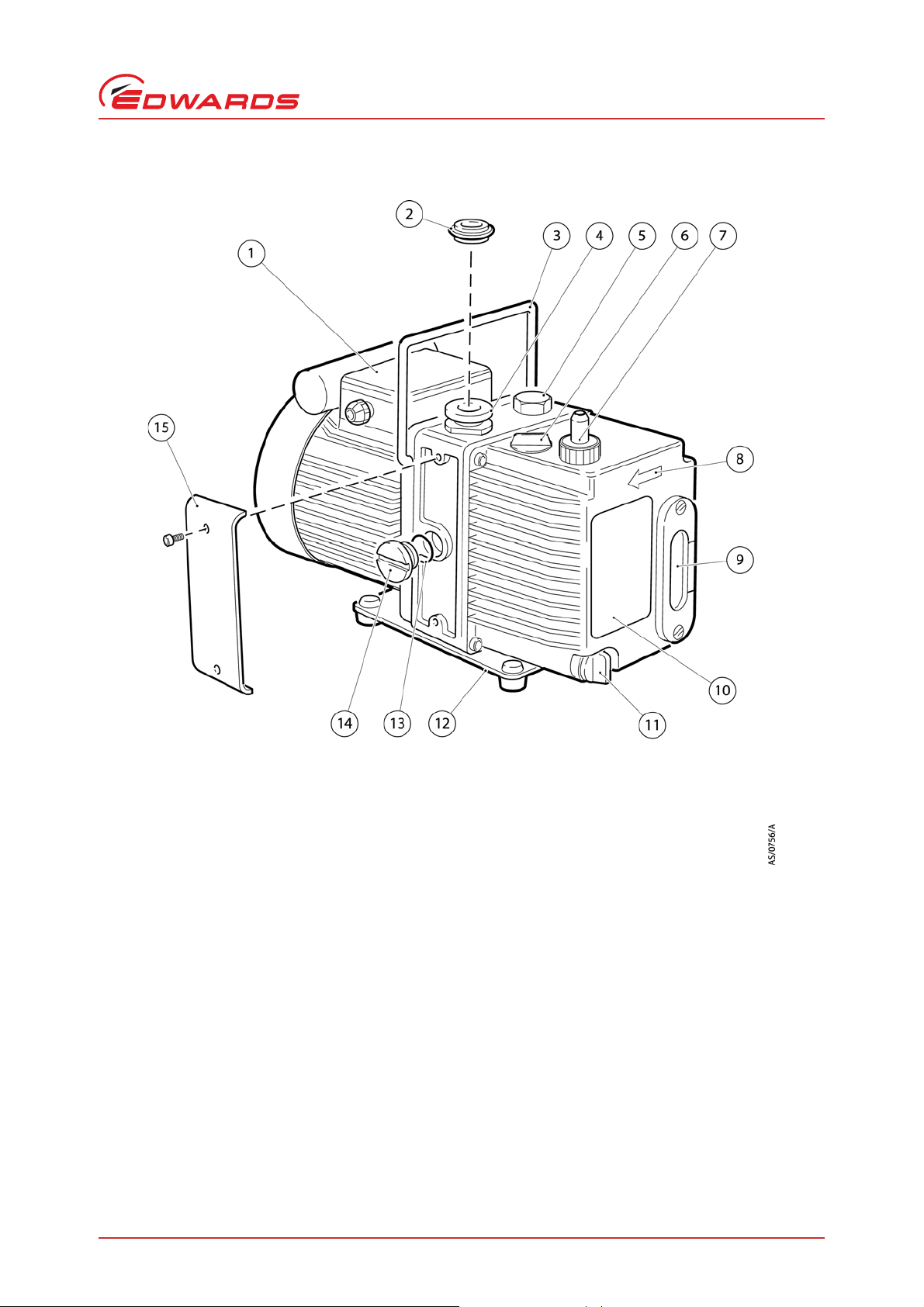
Figure 1 - The E2M0.7 and E2M1.5 pump
1. Motor terminal box
2. NW10 centring ring and O-ring (supplied)
3. Handle (removable: refer to Section 3.4)
4. NW10 inlet port (adaptor flange)
5. Gas-ballast control
6. Oil filler-plug
7. Outlet nozzle
8. Pump/motor shaft rotation direction arrow
9. Oil sight-glass and bezel
10.Pump identification label
11.Oil drain-plug
12.Baseplate
13.O-ring
14.Blanking plug (side inlet-port)
15.Removable side panel
A371–22–880 Issue R
Introduction
© Edwards Limited 2013. All rights reserved. Page 3
Edwards and the Edwards logo are trademarks of Edwards Limited.
Page 10

A371–22–880 Issue R
Introduction
1.3 Description
The Edwards E2M0.7 and E2M1.5 pump is shown in Figure 1. Refer to Figure 1 for item numbers in brackets in the
following descriptions.
The E2M0.7 and E2M1.5 pumps are two-stage, direct drive, sli ding vane pumps . The pump is oil-sealed and designed
for reliable, long-term operation. The pump is a free-standing unit. The drive is provided through a coupling by a
single-phase motor.
The motor is totally enclosed and is cooled by the motor-cooling fan which directs air along the motor fins. The
motors are fitted with a thermal overload device. When the motor is too hot, the thermal overload device switches
off the pump. The thermal overload device has an automatic reset; when the motor cools down, the device resets
and the motor will restart.
An oil pressure system lubricates the pump shaft bearing surfaces and rotor sealing faces. The pump has an oil
distribution valve which prevents discharge of oil to the pump interior (suckback) after the pump stops. The pumping
chambers are air-tight, so this arrangement prevents oil suckback unless the gas-ballast valve is open. For protection
in this case, refer to Section 1.4.
The level and condition of the oil in the oil box reservoir can be inspected through the sight-glass (9). An oil fillerplug (6) is fitted to the top of the oil box. An oil drain-plug (11) is fitted at the bottom of the oil box.
The pump has a carrying handle (3), inlet-port (4), outlet nozzle (7) and gas-ballast control (5). The pump is mounted
on a steel baseplate (12) on rubber pads. Details of suitable vibration is olators and other reco mmende d acce ssories
are given in Section 7.4.
1.4 Gas-ballast
To pump high vapour loads, gas-ballast is delivered into the pump to prevent condensation of the vapour carried by
the pumped gases.
Air (or another gas) can be introduced into the low vacuum stage through the gas-ballast control. The gas-ballast
control is a multi-turn valve that can be adjusted, as required, between closed and fully open.
Page 4 © Edwards Limited 2013. All rights reserved.
Edwards and the Edwards logo are trademarks of Edwards Limited.
Page 11

A371–22–880 Issue R
2Technical data
Note: To comply with EN61010 and CSA standards, the pump must be installed and used indoors, and within the
operating conditions specified in Table 1.
2.1 Operating and storage conditions
Table 1 - Operating and storage conditions
Ambient temperature range (operation) 12 to 40°C (53.6 to 104°F)
Ambient temperature range (storage) -30 to 70°C (-22 to 158°F)
Normal surface temperature of the pump-body
*
Maximum humidity (operation) 90% RH
Maximum altitude (operation) 2000 m (6561 ft)
Pollution degree 2
Installation category II
*
At ultimate vacuum, with ambient temperature of 20°C (68°F).
50 to 70°C (122 to 158°F)
Technical data
2.2 Performance
Note: Where total pressures are shown below, the measurements were taken using an untrapped total pressure
capacitance diaphragm gauge on a header, as specified by Pneurop 6602.
Table 2 - Performance data
Maximum displacement E2M0.7 E2M1.5
3 h-1
50 Hz electrical supply 0.9 m
60 Hz electrical supply 1.1 m
(0.53 ft3 min-1)1.8 m
3 h-1
(0.65 ft3 min-1)2.2 m
Maximum pumping speed – Pneurop
50 Hz electrical supply 0.75 m3 h-1 (0.44 ft3 min-1)1.6 m
3 h-1
60 Hz electrical supply 0.95 m
(0.56 ft3 min-1)2.0 m
Motor rotational speed
50 Hz electrical supply 1400 r min
60 Hz electrical supply 1700 r min
-1
-1
Ultimate vacuum
without gas-ballast (partial pressure) 7 x 10⁻⁴ mbar, 7 x 10⁻² Pa
(5.2 x 10
-4
Torr)
without gas-ballast (total pressure) 3 x 10⁻³ mbar, 3 x 10⁻¹ Pa
(2.2 x 10⁻³ Torr)
-1
with full gas-ballast (partial pressure) 2 x 10
mbar, 2 x 10⁻¹ Pa
(1.5 x 10⁻¹ Torr)
Maximum water vapour inlet pressure 15 mbar (11.2 Torr) 15 mbar (11.2 Torr)
Maximum water vapour pumping rate 8 g h
Maximum permitted outlet pressure
(at full pump throughout)
-1
0.5 bar gauge
1.5 bar absolute
1.5 x 10
5
Pa (21 .75 psi)
3 h-1
(1.06 ft3 min-1)
3 h-1
(1.30 ft3 min-1)
3 h-1
(0.94 ft3 min-1)
3 h-1
(1.18 ft3 min-1)
2800 r min
3400 r min
5 x 10
(3.7 x 10
-1
-1
-4
mbar, 5 x 10⁻² Pa
-4
Torr)
1.5 x 10⁻³ mbar, 1.5 x 10⁻¹ Pa
(1.1 x 10⁻³ Torr)
2.5 x 10⁻² mbar, 2.5 Pa
(1.9 x 10⁻² Torr)
-1
16 g h
0.5 bar gauge
1.5 bar absolute
1.5 x 10⁵ Pa (21.75 psi)
© Edwards Limited 2013. All rights reserved. Page 5
Edwards and the Edwards logo are trademarks of Edwards Limited.
Page 12

A371–22–880 Issue R
Technical data
2.3 Mechanical data
Table 3 - Mechanical data
Approximate pump mass 10 kg (22 lbs)
Dimensions Refer to Figure 2
Degree of protection (IEC34-5:1981) IP54
3
Pump inlet port NW10 (the flange can b e re mov ed f rom t he
Pump outlet port 11 mm external diameter nozzle (the nozzle can be removed from
Noise level at 1 metre 54 dB(A)
3
/8 inch BSP tapped hole)
the
2.4 Electrical data
The motor start-up current is drawn for less than one second, therefore slow-blow fuses must be used to prevent
unnecessary fuse failure when the pump starts. If the pump is used at temperatures lower than 12°C (53.6°F), the
start-up current will be drawn for longer; this may cause the motor thermal overload device to open.
Table 4 - Electrical data
/8 inch BSP tapped hole)
Continuous motor output rating
E2M0.7 0.09 kW
E2M1.5 0.16 kW
Motor electrical supply
E2M0.7 Single phase
E2M1.5 Single phase
Pump
E2M0.7 110-115 50 1.8 5.7 10
E2M1.5 110-115 50 3.1 12.0 10
*
Fuses should be EN60269 Section 2.2 or to BS 1362.
Nominal supply
(V)
115-120 60 1.9 5.3 10
220-240 50 1.0 2.8 6
230-240 60 1.0 2.3 6
115-120 60 2.6 11.2 10
220-240 50 1.4 5.5 6
230-240 60 1.3 5.2 6
Frequency
(Hz)
Full load current
(A)
Start-up current
(A)
Maximum fuse
rating (A)
*
Page 6 © Edwards Limited 2013. All rights reserved.
Edwards and the Edwards logo are trademarks of Edwards Limited.
Page 13

2.5 Lubrication data
A. 160 (6.3) for 220/240 V motors, 189 (7.4) for 110/120 V motors
1. Handle (removable: refer to Section 3.4)
2. 110/120 V motor
Note: An Edwards Safety Data Sheet for Ultragrade 15 is available on request.
Table 5 - Lubrication data
A371–22–880 Issue R
Technical data
Recommended oil
Maximum oil capacity 0.32 litre
*
To operate the pump when the ambient temperature is outside the range specified in Section 2.1, or to
optimise pump performance when you process condensable vapours, a different oil may be required.
*
Figure 2 - Dimensions: mm (inches)
Ultragrade 15
© Edwards Limited 2013. All rights reserved. Page 7
Edwards and the Edwards logo are trademarks of Edwards Limited.
Page 14

A371–22–880 Issue R
This page has been intentionally left blank.
Page 8 © Edwards Limited 2013. All rights reserved.
Edwards and the Edwards logo are trademarks of Edwards Limited.
Page 15

3 Installation
WARNING
WARNING
3.1 Safety
If a hydrocarbon oil is used in this pump, do not use the pump to process oxygen in concentrations
greater than 25% in volume. There is a risk of fire or explosion in the oil-box of the pump.
Edwards recommend that the E2M0.7 or E2M1.5 pumps are not used to pump hazardous
substances.
Obey the safety instructions in this Section and take note of appropriate precautions. If not, injury
to people and damage to equipment can result.
Prevent any part of the human body from coming into contact with the vacuum.
A371–22–880 Issue R
Installation
You must ensure that the pump is suitable for your application, If you have any doubts as to the suitability of the
pump for your application, refer to the Edwards guidelines on vacuum pump and vacuum system safety (see the
Associated publication at the end of the contents list at the front of this manual).
A suitably trained and supervised technician must install your pump. Obey the safety instructions listed below when
installing the pump, especially when connecting the pump into an existing system. Details of specific safety
precautions are given at the appropriate point in the instructions.
Wear the appropriate safety-clothing w hen in contact with contaminated components.
Vent and purge the vacuum system before installation work is started.
Ensure that the installation technician is familiar with the safety procedures that relate to the pump-oil and
the products handled by the pumping system. Take suitable precautions to avoid the inhalation of oil mist
and excessive skin contact with pump-oil, as prolonged exposure can be harmful.
Disconnect the other components in the pumping system from the electrical supply so that they cannot be
operated accidentally.
3.2 System design
Consider the following points when designing your pumping system:
Use a suitable valve to isolate the pump from the vacuum system, if the pump needs to warm up before
condensable vapours are pumped, or if the vacuum needs to be maintained when the pump is switched off.
Avoid high levels of heat input to the pump from the process gases, otherwise the pump may overheat and
seize, and cause the motor thermal overload device to open.
If the pump is used in a high ambient temperature and have a high gas throughput, the temperatu re of the
pump-body may exceed 70°C (158°F) and suitable guards must be fitted to prevent contact with hot
surfaces.
Make sure that the exhaust pipeline cannot become blocked. If an exhaust-isolation valve is fitted, make
sure the pump cannot be operated with the valve closed.
Provide for a purge of inert gas when the pumping system is shut down, to dilute dangerous gases to safe
concentrations. A suitable gas-ballast control valve for introduction of purge gas into the pump is available
as an accessory (refer to Section 7.4.11).
© Edwards Limited 2013. All rights reserved. Page 9
Edwards and the Edwards logo are trademarks of Edwards Limited.
Page 16

A371–22–880 Issue R
Installation
3.3 Unpack and inspect
1. Remove all packing materials and protective covers and check the pump. If the pump is damaged, notify your
supplier and the carrier in writing within three days; state the Item Number of the pump together with your
order number and your supplier's invoice number. R etain all packing materials for inspection. Do not use the
pump if it is damaged.
2. Check that your package contains the items listed in Table 6. If any of these items is missing, notify your supplier
within three days.
If the pump is not to be used immediately, replace the protective covers. Store the pump in suitable conditions, as
described in Section 6.1.
Table 6 - Checklist of items
Quantity Description Check ()
1Rotary vacuum pump
(1) Fitting pack containing the following:
1 Hexagon wrench, 4 mm
1 Hexagon wrench, 6 mm
1 NW10 centring ring
1 O-ring for centring
1 O-ring for outlet port
3.4 Locate the pump
The pump can be either free-standing on its b aseplate which is fitted with rubber pads; fixed by four fixing bolt holes
in the baseplate; or used with vibration isolators. For the location of the fixing holes in the baseplate, refer to
Figure 2. Provide a firm, level platform for the pump.
Locate the pump so that the oil level sight-glass is visible and the oil filler-plug, oil drain-plug, mode selector and
gas-ballast control are accessible.
If the pump is part of a permanent installation the handle can be removed to make the pump more compact. To
remove the handle, cut the handle in half, then remove the two halves from the pump.
If the pump will be located inside an enclosure, ensure that there is adequate ventilation at both ends of the pump,
so that the ambient temperature around the pump does not exceed 40°C. There must be a minimum space of 25 mm
between the pump and enclosure walls.
3.5 Fill the pump with oil
Fill the pump with oil as described below. Refer to Figure 1 for the item numbers in brackets.
1. Remove the oil filler-plug (6).
2. Pour oil int o the pump un til the oil -level just reaches the MAX mark on the bezel at the top of the sight-glass (9).
If the oil-level goes above the MAX mark, remove the drain-plug (11) and drain the excess oil from the pump.
3. After a few minutes, recheck the oil-level. If the oil-level is now below the MAX mark, pour more oil into the
pump.
4. Refit the oil filler-plug. Tighten the plug firmly by hand. Do not overtighten.
Page 10 © Edwards Limited 2013. All rights reserved.
Edwards and the Edwards logo are trademarks of Edwards Limited.
Page 17

A371–22–880 Issue R
CAUTION
WARNING
3.6 Electrical installation
Ensure that the electrical installation of the pump conforms with your local and national safety
requirements. It must be connected to a suitably fused and protected electrical supply and a
suitable earth (ground) point.
Note: The following instructions for connecting the pump to an electrical supply are not applicable to pumps
fitted with an integral (non-detachable) electrical supply cable.
3.6.1 Connect the pump to your electrical supply
Note: The pump will restart automatically when the electrical supply is restored after an interruption and when
the pump cools after it has overheated. If you do not want the pump to restart automatically, use electrical
control equipment that must be reset manually.
Ensure that your electrical supply voltage corresponds with the voltage specified on the motor data plate. Refer to
Section 2.4 for fuse recommendations, and refer to Figure 3 for a schematic of the electrical connections. The
diameter of the outer sheath of the supply cable must be wi thin the range 5 to 8 mm. The supply cable must conform
in size and colour coding with your local and national electrical installation regulations. The temperature rating of
the cable must be 70°C (158°F) or greater.
Installation
1. Remove the cover from the motor terminal box (Figure 1, item 1). Take out the plastic cable gland which is
supplied loose inside.
2. Screw the plastic cable gland into the hole in the side of the motor terminal box. Using a tool this should be
tightened to a torque of 3.75 Nm.
3. Thread the supply cables through the gland and connect to the appropriate terminals, as shown in Figure 3. The
earth (ground) terminal connection must be tightened to a torque of 2.13 to 2.87 Nm (1.57 to 2.11 lbf ft).
4. Tighten the dome shaped nut on the cable gland until the outer sheath of the cable is firmly gripped. Using a
tool this should be tightened to a torque of 2.5 Nm, do not overtighten.
5. Check that the cable connections are correct, then replace the cover on the motor terminal box.
3.6.2 Check the direction of rotation
Ensure that the pump-motor rotates in the correct direction. If it does not, the pump and your vacuum system
can become pressurised.
Refer to Figure 1.
1. Watch the motor-cooling fan through the fan cover on the end of the motor.
2. Switch on the electrical supply to the motor for a few seconds.
3. Check that the motor-cooling fan rotates in the direction shown by the arrow (8) on the end of the oil box. If the
rotation direction is incorrect, immediately switch off the electrical supply, ch eck the wiring to the pump motor
and correct as necessary.
© Edwards Limited 2013. All rights reserved. Page 11
Edwards and the Edwards logo are trademarks of Edwards Limited.
Page 18

A371–22–880 Issue R
A. Capacitor
B. Main motor winding
C. Auxiliary motor winding
D. Thermal protector
E. Earth (ground)
L. Live
N. Neutral
Earth (ground) connector
1. Motor terminals
2. Motor terminal box
* Colour not significant
Installation
Figure 3 - Electrical supply connection
3.7 Connect the pump inlet
3.7.1 General requirements
To connect the pump to the vacuum system, use either the inlet-port on the top of the pump (Figure 1, item 4) or
the inlet-port on the side of the pump (Figure 1, item 14). Refer to the procedure in Section 3.7.2 for instructions on
using the side inlet port.
When using either the top or the side inlet-port, it is possible t o:
Connect to the NW10 flange supplied on the pump; use the centring ring and O-ring supplied.
Remove the NW10 flange and connect to the
Remove the NW10 flange and replace it with a NW25 flange adaptor (available as an optional accessory, see
Section 7.4) and then connect to the NW25 flange.
Take note of the following information when connecting the pump to the vacuum system. Refer to Section 7.4 for
details of the accessories mentioned below.
For optimum pumping speeds, ensure that the pipeline connected to the inlet-port is as short as possible and
has an internal diameter not less than the inlet-port diameter.
Support the vacuum pipelines to prevent loading of the coupling-joints.
Page 12 © Edwards Limited 2013. All rights reserved.
3
/8 inch BSP threaded hole.
Edwards and the Edwards logo are trademarks of Edwards Limited.
Page 19

A371–22–880 Issue R
WARNING
If necessary, incorporate flexible bellows in the system pip elines to redu ce the transmission of vibration and
to prevent loading of coupling-joints. If using flexible bellows, ensure that the bellows used have a maximum
pressure rating that is greater than the highest pr essure that can be generated in the system. W e recommend
that Edwards flexible bellows are used.
Use a suitable inlet-filter if condensable vapours are pumped or if the pump is used for very dusty
applications.
Use a suitable valve to isolate the pump from the vacuum system if pumping condensable vapours or to
maintain vacuum when the pump is switched off.
Ensure that sealing surfaces are clean and scratch-free.
3.7.2 Side inlet-port connection
Refer to Figure 1. A side inlet-port is available; use the following procedure for instructions on using this port.
1. Carefully remove the side pa nel (15) from the pu mp: use a suitable flat blade screwdriver or similar tool for this
purpose. The panel is secured by two nylon rivets.
2. Unscrew and remove the blanking plug (14) with its O-ring (13).
3. Unscrew and remove the adaptor flange (4) and its O-ring and replace it with the blanking plug and O-ring that
you removed in Step 2.
Installation
4. Screw the adaptor flange and its O-ring into the side inlet-port.
3.8 Connect the pump outlet
Connect the pump outlet to a suitable treatment plant to prevent the discharge of dangerous gases
and vapours to the surrounding atmosphere. Use a catchpot to prevent the drainage of
contaminated condensate back into the pump.
To connect the pump to your outlet accessories or to your exhaust treatment plant, you can:
Connect 10 mm internal diameter vacuum hose or 12 mm internal diameter plastic hose to the outlet nozzle
(Figure 1, item 7).
Remove the outlet nozzle and connect to the
Remove the outlet nozzle and replace it with an NW25 flange adaptor (available as an optional accessory,
refer to Section 7.4) and then connect to the NW25 flange.
Take note of the following information before connecting to the pump outlet:
The exhaust system must be configured so that the maximum pressure at the pump outlet does not exceed
0.5 bar gauge (1.5 bar absolute, 1.5 x 10
In the following circumstances, Edwards recommend an oil mist filter is fitted to the pump outlet
if the pump is used with the gas-ballast control open
3
/8 inch BSP tapped hole.
5
Pa, 21.75 psi) at full pump throughput.
if the pump is operated with an inlet pressure greater than 10 mbar (7.5 Torr) for extended periods or
if the pump is frequently pumped down from atmospheric pressure.
The mist filter will trap the oil exhausted from the pump: the oil can be re-used if it is not contaminated.
3.9 Leak-test the system
Leak-test the system and seal any leaks found after the pump is installed, to prevent leakage of substances out of
the system and leakage of air into the system.
© Edwards Limited 2013. All rights reserved. Page 13
Edwards and the Edwards logo are trademarks of Edwards Limited.
Page 20

A371–22–880 Issue R
This page has been intentionally left blank.
Page 14 © Edwards Limited 2013. All rights reserved.
Edwards and the Edwards logo are trademarks of Edwards Limited.
Page 21

A371–22–880 Issue R
WARNING
WARNING
4 Operation
Do not expose any part of your body to vacuum. If you do, you may be injured.
4.1 ATEX directive implications
4.1.1 Introduction
This equipment is designed to meet the requirements of Group II Category 3 equipment in accordance with Directive
94/9/EC of the European Parliament and the Council of 23rd March 1994 on the approximation of the laws of the
Member States concerning equipment and protective systems intended for use in potentially explosive atmospheres.
(The ATEX Directive)
The ATEX Category 3 applies in respect of potential ignition sources internal to the equipment. An ATEX Category has
not been assigned in respect of potential ignition sources on the outside of the equipment as the equipment has not
been designed for use where there is an external potentially explosive atmosphere.
Operation
There is no potential source of ignition within the pump during normal operation but there may be potential sources
of ignition under conditions of predictable and rare malfunction as defined in the Directive. Accordingly, although
the pump is designed to pump flammable materials and mixtures, operating pr ocedures should ensure that under all
normal and reasonably predictable conditions, these materia ls and mixtures are not within explosive limits. Category
3 is considered appropriate for the avoidance of ignition in the case of a rare malfunction which allows flammable
materials or mixtures to pass through the pump whilst within their explosive limits.
4.1.2 Flammable/pyrophoric materials
You must obey the instructions and take note of the precautions given below, to ensure that
pumped gases do not enter their flammable ranges.
When flammable or pyrophoric materials are present within the equipment you must:
Not allow air to enter the equipment.
Ensure that the system is leak tight.
Use an inert gas purge (for example, a nitrogen purge) to dilute any flammable gases or vapours entering the
pump inlet, and/or use an inert gas purge to reduce the concentration of flammable gases or vapours in the
pump and in the exhaust pipeline to less than one quarter of the gases' published lower explosive limits
(LEL).
Use an inert gas purge into the pump gas ballast connection to prevent the condensation of flammable
vapours within the pump mechanism and exhaust pipeline.
© Edwards Limited 2013. All rights reserved. Page 15
Edwards and the Edwards logo are trademarks of Edwards Limited.
Page 22

A371–22–880 Issue R
WARNING
WARNING
Operation
4.1.3 Gas purges
If inert gas purges are used to dilute dangerous gases to a safe level, ensure that the pump is shut
down if an inert gas supply fails.
You must obey the instructions and take note of the precautions given below, to ensure that
pumped gases do not enter their flammable ranges.
Switch on the inert gas purge to remove air from the pump and the exhaust pipeline before the process starts. Switch
off the purge flow at the end of the process only after an y remaining flammable gases or vapours have been purged
from the pump and exhaust pipeline.
If liquids that produce flammable vapours could be present in the pump foreline, then the inert gas purge to the
pump should be left on all the time this liquid is present. Flammable liquids could be present in the foreline as a
result of condensation, or may be carried over from the process.
When calculating the flow rate of inert gas required for dilution, consider the maximum flow rate for the fla mmable
gases/vapours that could occur. For example, if a mass flow controller is used to supply flammable gases to the
process, assume a flow rate for flammable gases that could arise if the mass flow controller is fully open.
Continually measure the inert gas purge flow rate: if the flow rate falls below that required, you must stop the flow
of flammable gases or vapours into the pump.
Note: We recommend that you obtain and read the Vacuum Pump and Vacuum System Safety manual (publication
number P400-40-100), available from Edwards or your supplier.
4.2 Gas-ballast control
Use the gas-ballast control (Figure 1, item 5) to change the amount of air (or inert gas) introduced into the low
vacuum stage of the pump. Use of the gas-ballast will prevent the condensation of vapours in the pump; the
condensates would contaminate the oil.
Use the gas-ballast control closed:
to achieve ultimate vacuum
to pump dry gases.
Turn the gas-ballast control six turns anti-clockwise to open it fully. Use the gas-ballast control open:
to pump high concentrations of condensable vapour
to decontaminate the oil.
When you operate the pump with the gas-ballast control open, there will be an increased rate of oil loss from the
pump.
Page 16 © Edwards Limited 2013. All rights reserved.
Edwards and the Edwards logo are trademarks of Edwards Limited.
Page 23

A371–22–880 Issue R
WARNING
4.3 Start-up procedure
Ensure that your system design does not allow the exhaust pipeline to be blocked.
If the oil is contaminated, or if the pump temperature is below 12°C (54°F), or if the electrical supply voltage is more
than 10% below the lowest voltage specified for the pump, the pump may operate at a reduced speed for a few
minutes. If the pump continues to operate at reduced speed, the motor thermal overload device will open and stop
the pump. When the motor has cooled, the thermal overload device will reset automatically and the pump will
restart.
1. Check that the pump oil-level is between the MAX and MIN marks on the bezel of the oil-level sight-glass; if it is
not, refer to Section 5.3.
2. Turn the gas-ballast control to the required position (refer to Section 4.2).
3. Switch on the electrical supply to the pump.
4. Check that the oil-level in the sight-glass drops slightly (3 to 5 mm, 0.1 to 0.2 inches) afte r start-up . This sho ws
that the pump has primed with oil.
Operation
5. If the pump fails to prime, operate the pump with the inlet open to atmosphere for approximately 30 seconds.
Then isolate the inlet and check that the oil-level drops by 3 to 5 mm (0.1 to 0.2 inches).
6. To achieve ultimate vacuum, to pump condensable vapours or to decontaminate the pump oil, refer to the
procedures in Sections 4.4, 4.5 and 4.6 respectively. Otherwise, open the vacuum system isolation-valve.
4.4 To achieve ultimate vacuum
If the pump does not achieve the performance specified in Section 2.2, make sure that this is not due to your system
design before you contact your supplier or Edwards for advice, In pa rticular, the vapour pressure of all mate rials used
in your vacuum system (including pump oil, see below) must be much lower than the specified ultimate vacuum of
the pump. Refer to Table 8 for a list of possible causes for failure to achieve the specified performance; note however
that the most common causes are:
The pressure measurement technique or gauge head is unsuitable or the gauge head is faulty.
Oil other than that recommended has been used and the vapour pressure of the oil is higher than the
specified ultimate vacuum of the pump.
Use the following procedure to achieve ultimate vacuum:
1. Isolate the pump from your vacuum system.
2. Turn the gas-ballast control fully anti-clockwise (fully open) and operate the pump for at least 1 hour (or
overnight) to thoroughly purge the oil of contaminants.
3. Close the gas-ballast control.
4. Open the vacuum system isolation-valve and pump down to ultimate vacuum.
© Edwards Limited 2013. All rights reserved. Page 17
Edwards and the Edwards logo are trademarks of Edwards Limited.
Page 24

A371–22–880 Issue R
Operation
4.5 To pump condensable vapours
Use gas-ballast (open the gas-ballast control) when there is a high proportion of condensable vapours in the process
gases.
1. Close the vacuum system isolation-valve.
2. Turn the gas-ballast control anti-clockwise to the fully open position, and operate the pump for 30 minutes to
warm the oil; this will help to preven t vapour condensation in the pump.
3. Open the vacuum system isolation-valve and continue to operate the pump with the gas-ballast control open.
After condensable vapours have been pumped, decontaminate the oil (if necessary); use the procedure in
Section 4.6.
4.6 To decontaminate the oil
The oil in the pump should be clear, if the oil is cloudy or discoloured, it is contaminated with process vapours.
1. Look at the condition of the oil in the oil sight-glass (Figure 1, item 9). If the oil is cloudy or discoloured,
continue with the procedure at Step 2 below.
2. Close the vacuum system isolation-valve.
3. Turn the gas-ballast control fully anti-clockwise.
4. Operate the pump until the oil is clear.
4.7 Unattended operation
The pump is designed for unattended operation under the normal operating conditions specified in Section 2.
However, Edwards recommend checking the pump at a regular interval of not more than 14 days; check the pump
more frequently if pumping high volumes of gas or if operating the pump with the gas-ballast control open.
The motor is protected by an overload device which isolates the pump from the electrical supply when critical
temperature or current levels are exceeded. The overload device resets automatically when the motor has cooled.
When checking the pump, make sure that the pump is not going through a repetitive cycle of thermal overload
failures and automatic resets. If necessary reduce the thermal load from the pumped gases, to prevent overheating
of the pump.
4.8 Shut-down
Note: If the gas-ballast control is open and the motor is switched off for any reason, the pump drive shaft may
rotate in the reverse direction, causing a system pressure rise. To prevent this, use a gas-ballast control
valve (refer to Section 7.4.11).
Edwards recommend, as described in the procedure below, that the oil is decontaminate d before the p ump is shut
down; this will prevent damage to the pump by the contaminates in the oil.
1. Refer to Section 4.6 and decontaminate the oil, as required.
2. Close the vacuum system isolation-valve (if not already closed).
3. Close gas-ballast (that is, turn the gas-ballast control clockwise).
4. Switch off the electrical supply to the pump.
Page 18 © Edwards Limited 2013. All rights reserved.
Edwards and the Edwards logo are trademarks of Edwards Limited.
Page 25

A371–22–880 Issue R
WARNING
5Maintenance
5.1 Safety information
Obey the safety instructions given below and take note of appropriate precautions. If you do not,
you can cause injury to people and damage to equipment.
A suitably trained and supervised technician must maintain the pump. Obey your local and national safety
requirements.
Ensure that the maintenance technician is familiar with the safety procedures which relate to the pump-oil
and the products processed by the pumping-system.
Allow the pump to cool to a safe temperature before starting maintenance work.
Isolate the pump and other components in the pumping system from the electrical supply so that they can
not be operated accidentally.
After maintenance is completed, recheck the pump rotation direction if the electrical supply has been
disconnected.
Maintenance
Do not reuse O-rings and seals if they are damaged.
The pump and its fluid will be contaminated with the process chemicals that have been pumped during
operation. Ensure that the pump is decontaminated before maintenance and that adequate precautions are
taken to protect people from the effects of dangerous substances if contamination has occurred.
Do not touch or inhale the thermal breakdown products of fluorinated materials which may be present if the
pump has been heated to 260°C (500°F) and above. These breakdown products are very dangerous.
Fluorinated materials in the pump may include oils, greases and seals. The pump may have overheated if it
was misused, if it malfunctioned or if it was in a fire. Edwards Material Safety Data Sheets for fluorinated
materials used in the pump are available on request: contact your supplier or Edwards.
Leak-test the system after maintenance work is complete if you have connected or disconnected any vacuum
or exhaust joints; seal any leaks found.
5.2 Maintenance plan
The plan shown in Table 7 details the routine maintenance operations necessary to maintain the pump in normal use.
Instructions for each operation are given in the section shown.
More frequent maintenance may be required if the pump is used to proces s corrosive or abrasive gase s and vapours;
in these circumstances, Edwards recommend that the pump seals are replaced every year. If necessary, adjust the
maintenance plan according to your experience.
When maintaining the pump, use Edwards spares and maintenance kits; these contain all of the components
necessary to complete maintenance operations successfully. The Item Numbers of the spares and kits are given in
Section 7.
Examine the condition of any external accessories, filters or traps (if fitted) when maintaining the pump. Refer to
the instructions supplied with the accessories for the necessary maintenance procedures.
© Edwards Limited 2013. All rights reserved. Page 19
Edwards and the Edwards logo are trademarks of Edwards Limited.
Page 26

A371–22–880 Issue R
Maintenance
Table 7 - Maintenance plan
Operation Frequency Refer to Section
Check the oil-level Monthly 5.3
Replace the oil Every 3000 hours of operation 5.4
Inspect and clean the inlet-filter Every oil change 5.5
Clean or replace the gas-ballast O-ring Every oil change 5.6
Clean the motor fan-cover Yearly 5.7
Clean and overhaul the pump Every 15000 hours of operation 5.8
Fit new blades Every 30000 hours of operation 5.9
Replace the capacitor Every 4 years 5.10
Test the motor condition Every 15000 hours of operation 5.10
5.3 Check the oil-level
Note: If required, the oil-level can be checked while the pump is operating, however the pump must be switched
off and isolated and other components in the pumping system from the electrical supply before oil is poured
into the pump.
Refer to Figure 1 for the items in brackets.
1. Check that the oil-level in the sight-glass (9) is between the MAX and MIN level marks on the bezel of the sightglass.
2. If the oil-level is near to or below the MIN level mark, remove the filler-plug (6) and pour more oil into the
reservoir until the oil reaches the MAX level mark. If the oil-level goes above the MAX mark, remove the drainplug (11) and drain the excess oil from the pump. Refit the filler-plug.
3. If the oil is contaminated, drain and refill the pump with clean oil as described in Section 5.4.
5.4 Replace the oil
Refer to Figure 1 for the items in brackets.
1. Operate the pump for approximately ten minutes to warm the oil, then switch off the pump. (this lowers the
viscosity of the oil and enables it to be drained from the pump more easily).
2. Isolate the pump from your electrical supply and disconnect it from the vacuum system.
3. Remove the oil filler-plug (6).
4. Place a suitable block under the pump-motor to tilt the pump and place a suitable container under the drainplug (11). Remove the drain-plug and allow the oil to drain into the container.
5. If the oil is dirty or contaminated, pour clean oil into the pump and allow it to drain out of the pump. Repeat
this step until the oil reservoir is clean.
6. Refit the drain-plug, remove the block and reconnect the pump to the vacuum system.
7. Fill a suitable container with clean oil and pour the oil into the filler hole until the oil-level reaches the MAX
level mark on the bezel of the sight-glass (9).
8. Allow a few minutes for the oil to drain into the pump. If necessary, add more oil. Refit the filler-plug.
Page 20 © Edwards Limited 2013. All rights reserved.
Edwards and the Edwards logo are trademarks of Edwards Limited.
Page 27

5.5 Inspect and clean the inlet-filter
1. Inlet adaptor
2. Inlet-filter
3. O-ring
1. Refer to Figure 4. Unscrew the inlet adaptor (1) and remove the inlet-filter (2) and O-ring (3).
2. Wash the filter in a suitable cleaning solution. Allow the filter to dry.
3. Refit the O-ring (3), inlet-filter (2) and inlet adaptor (1).
Figure 4 - Inlet-filter removal and replacement
A371–22–880 Issue R
Maintenance
5.6 Clean or replace the gas-ballast O-ring
Note: The filter element (Figure 5, item 3) is retained in its seating with adhesive; do not try to remove it.
Refer to Figure 5.
1. Unscrew and remove the gas-ballast control (1).
2. Remove the O-ring (2) from the control.
3. Wash the O-ring in a suitable cleaning solution. Replace the O-ring if it is damaged.
4. Fit the O-ring carefully on its seat. Screw the gas-ballast co ntrol back into the pump, and reset to the required
position.
© Edwards Limited 2013. All rights reserved. Page 21
Edwards and the Edwards logo are trademarks of Edwards Limited.
Page 28

A371–22–880 Issue R
1. Gas-ballast control
2. O-ring
3. Filter element
Maintenance
Figure 5 - Gas-ballast O-ring removal and replacement
5.7 Clean the motor fan-cover and enclosure
If the motor fan-cover and enclosure are not kept clean, the air-flow over the motor can be restricted and the pump
may overheat.
1. Switch off the pump and disconnect it from the electrical supply.
2. Use a dry cloth and a soft brush to remove dirt and deposits from the fan-cover and enclosure.
5.8 Clean and overhaul the pump
Clean and overhaul the pump as described in the instruction supplied with the clean and overhaul kit (refer to
Section 7.3).
5.9 Fit new blades
Fit new blades to the pump as described in the instructions supplied with the blade kit (refer to Section 7.3).
5.10 Replace the capacitor and test the motor
Replace the capacitor as described in the instructions supplied with the capacitor kit.
Test the earth (ground) continuity and the insulation resistance of the pump motor, in accordance with local
regulations for periodic testing of electrical equipment. Edwards recommends that:
The earth (ground) continuity is less than 0.1 Ω.
Insulation resistance is greater than 10 MΩ.
If the motor fails these tests, the motor must be replaced.
5.11 Fault finding
A list of fault conditions and their possible causes is provided in Table 8 to assist in basic fault-finding. If unable to
rectify a fault when using this guide, call your supplier or your nearest Edwards Service Centre for advice.
Page 22 © Edwards Limited 2013. All rights reserved.
Edwards and the Edwards logo are trademarks of Edwards Limited.
Page 29

A371–22–880 Issue R
Table 8 - Fault finding
Fault condition Possible cause
The pump has failed to start The electrical supply fuse has failed.
The motor is incorrectly wired.
The operating voltage does not match that of the motor.
The exhaust filter or exhaust line is blocked.
The oil temperature is below 12°C (53.6°F).
The oil is too viscous.
The oil is contaminated.
The pump is seized after long storage, or has been left to stand
after pumping contaminants.
The motor is faulty.
The pump failed to achieve specified
performance (Failure to reach ultimate
vacuum)
The pump is noisy The motor fan-cover is damaged.
The pump surface temperature is above
100°C (212°F)
The vacuum is not maintained after the pump
is switched off
The pumping speed is poor The connecting pipelines are too small in diameter.
Your measuring technique or gauge is unsuitable.
There is a leak in the external vacuum system.
The gas-ballast control is open.
The oil level is too low.
You have filled the pump with the wrong type of oil.
The oil is contaminated.
The pump has not primed.
The vacuum fittings are dirty.
The inlet-filter is blocked.
The pump has not warmed up.
The motor bearings are worn.
The oil is contaminated with solid particles.
One of the pump blades is sticking.
The ambient temperature is too high.
The cooling-air supply is insufficient or is too hot.
The cooling-air supply is blocked.
The electrical supply voltage is too high.
The exhaust filter or exhaust line is blocked.
The oil level is too low.
The pump is filled with the wrong type of oil.
The oil is contaminated.
The process gas is too hot, or the throughput is too high.
The gas-ballast control is open.
O-ring (s) are damaged or missing.
The shaft seals have deteriorated.
The connecting pipelines are too long.
The inlet-filter is blocked.
Maintenance
© Edwards Limited 2013. All rights reserved. Page 23
Edwards and the Edwards logo are trademarks of Edwards Limited.
Page 30

A371–22–880 Issue R
Maintenance
Table 8 - Fault finding (continued)
Fault condition Possible cause
There is an external oil leak The oil pump shaft seal is worn or damaged.
The oil box O-ring has deteriorated.
There is an oil leak from gas-ballast control.
There is an oil-leak from the drain-plug.
Page 24 © Edwards Limited 2013. All rights reserved.
Edwards and the Edwards logo are trademarks of Edwards Limited.
Page 31

A371–22–880 Issue R
CAUTION
6 Storage and disposal
6.1 Storage
Observe the storage temperature limits stated in Section 2.1. Storage below -30°C (-22°F) will permanently
damage the pump seals.
Note: If the new pump is to be stored in conditions of high humidity, remove the pump from the packaging and
dispose of the packaging in accordance with the instruction in Section 6.2.
Use the following procedure to store the pump:
1. Shut-down the pump as described in Section 4.8.
2. Disconnect the pump from the electrical supply.
3. Purge the vacuum system and the pump with dry nitrogen and disconnect the pump from the vacuum system.
4. Replace the oil as described in Section 5.4.
Storage and disposal
5. Place and secure protective covers over the inlet and outlet-ports.
6. Store the pump in cool, dry conditions until required for use.
When required, prepare and install the pump as described in Section 3. If the pump has been stored for more than a
year, clean and overhaul the pump before installing it, as described in the instructions supplied with the clean and
overhaul kit.
6.2 Disposal
Dispose of the pump, the oil and any components removed from the pump safely in accordance with all local and
national safety and environmental requirements.
Take particular care with the following:
Components which have come into contact with the pump fluid.
Components which have been contaminated with dangerous process substances.
Do not incinerate fluoroelastomer seals and O-rings.
© Edwards Limited 2013. All rights reserved. Page 25
Edwards and the Edwards logo are trademarks of Edwards Limited.
Page 32

A371–22–880 Issue R
This page has been intentionally left blank.
Page 26 © Edwards Limited 2013. All rights reserved.
Edwards and the Edwards logo are trademarks of Edwards Limited.
Page 33

A371–22–880 Issue R
7 Service, spares and accessories
7.1 Introduction
Edwards products, spares and accessories are available from Edwards companies in Belgium, Brazil, China, France,
Germany, Israel, Italy, Japan, Korea, Singapore, United Kingdom, U.S.A and a world-wide network of distributors.
The majority of these centres employ Service Engineers who have undergone comprehensive Edwards training
courses.
Order spare parts and accessories from your nearest Edwards company or distributor. When you order, state for each
part required:
Model and Item Number of your equipment
Serial number
Item Number and description of part.
7.2 Service
Edwards products are supported by a world-wide network of Edwards Service Centres. Each Service Centre offers a
wide range of options including: equipment decontamination; service exchange; repair; rebuild and testing to factory
specifications. Equipment which has been serviced, repaired or rebuilt is returned with a full warranty.
Service, spares and accessories
Your local Service Centre can also provide Edwards engineers to support on-site maintenance, service or repair of
your equipment.
For more information about service options, contact your nearest Service Centre or other Edwards company.
7.3 Spares
The maintenance kits listed in Table 9 contain all of the parts you will need to maintain your pump. The maintenance
kits also include instructions for the use of the kits.
Use the Clean and Overhaul Kit for routine maintenance operations. Use the Blade Kit togeth er with the Clean and
Overhaul Kit when the blade assembly in the rotary pump must be renewed.
Table 9 - Spares Item Numbers
Maintenance kit Item Number
E2M0.7/E2M1.5 Clean and Overhaul Kit A371-01-131
E2M0.7/E2MI.5 Blade Kit A371-01-132
Ultragrade 15 oil, 1 litre H110-26-015
Capacitor kit for part numbers A371-31-902 / A371-22-902 / A371-03-902 (110-120 V 30 μF) A505-84-808
Capacitor kit for part numbers A371-31-919 / A371-22-919 / A371-03-919 (220-240 V 8 μF) A505-84-809
© Edwards Limited 2013. All rights reserved. Page 27
Edwards and the Edwards logo are trademarks of Edwards Limited.
Page 34

A371–22–880 Issue R
Service, spares and accessories
7.4 Accessories
7.4.1 Introduction
A comprehensive range of accessories is available for the pumps, as shown in Figure 6. Table 10 lists the Item
Numbers of these accessories, and the accessories are briefly de scribed in Sections 7.4.2 to 7.4.12.
Table 10 - Accessories Item Numbers
Accessory Refer to Section Item Number
IT020K Inlet catchpot
ITF20K Inlet dust filter
ITD20K Inlet desiccant trap
ITC20K Inlet chemical trap 7.4.5 A444-10-000
FL20K Foreline trap
EMF3 Outlet mist filter 7.4.7 A462-20-000
Oil drain extension 7.4.8 A505-03-000
Vibration isolators (pack of four) 7.4.9 A248-01-407
NW25 Pump inlet/outlet adaptor 7.4.10 A371-01-028
EBV20 gas-ballast control valve
220/240 V, single-phase, 50/60 Hz
100/120 V, single-phase, 50/60 Hz
PV10EK pipeline valve
200/240 V, single-phase, 50/60 Hz
110/127 V, single-phase, 50/60 Hz
*
These accessories require an NW25 adaptor: refer to Section 7.4.10.
*
*
*
*
*
7.4.2 A441-10-000
7.4.3 A442-15-000
7.4.4 A445-10-000
7.4.6 A133-05-000
7.4.11
7.4.12
A500-06-930
A500-06-984
C411-01-000
C411-03-000
7.4.2 Inlet catchpot
The inlet catchpot traps any liquid droplets and prevents their entry into the pump.
7.4.3 Inlet dust filter
The inlet dust filter protects the pump against abrasive dust.
7.4.4 Inlet desiccant trap
Use a desiccant trap when you pump limited quan tities of water vapour at high pumping speeds to a low vapour
pressure.
7.4.5 Inlet chemical trap
The inlet chemical trap protects the pump against chemically active gases.
7.4.6 Foreline trap
Use a Foreline trap on a clean pumping system to prevent back-migration of rotary pump oil vapour into the vacuum
system.
Page 28 © Edwards Limited 2013. All rights reserved.
Edwards and the Edwards logo are trademarks of Edwards Limited.
Page 35

Figure 6 - Accessories
1. Inlet catchpot
2. Inlet dust filter
3. Inlet desiccant trap
4. Inlet chemical trap
5. Foreline trap
6. Solenoid operated pipeline valve
7. Solenoid operated gas-ballast valve
8. Outlet mist filter
9. Flange adaptor kit
10.Vibration is olators
11.Oil drain extension
A371–22–880 Issue R
Service, spares and accessories
© Edwards Limited 2013. All rights reserved. Page 29
Edwards and the Edwards logo are trademarks of Edwards Limited.
Page 36

A371–22–880 Issue R
Service, spares and accessories
7.4.7 Outlet mist filter
The outlet mist filter separates and traps oil droplets to prevent oil mist discharge from the pump outlet.
7.4.8 Oil drain extension
Fit the oil drain extension between the oil drain port on the pump and the oil drain-plug to make the drainage of oil
from the pump easier. The pack includes an oil drain extension tube for use when oil is gravity drained.
7.4.9 Vibration isolators
The vibration isolators reduce transmission vibration and noise when the pu mp is floor or frame mounted, and helps
to reduce strain when the mounting area is uneven.
7.4.10 Pump inlet or outlet NW25 adaptor
This is a 3/8 inch BSP to NW25 adaptor, supplied with connection hardwa re. Use this adaptor when the NW10 adaptor
fitted to the pump-inlet or the outlet-nozzle fitted to the pump outlet are removed, to adapt the
to NW25.
3
/8 inch BSP thread
7.4.11 Solenoid operated gas-ballast control valve
The valve provides remote or automatic on/off control of gas-ballast. The valve can be connected to shut-off ballast
to prevent the return of air to the vacuum system when the pump is switched off.
7.4.12 Solenoid operated pipeline valve
Fit the pipeline valve between your vacu um system and the pump inlet to provide addi tional system protection when
the pump is switched off.
Page 30 © Edwards Limited 2013. All rights reserved.
Edwards and the Edwards logo are trademarks of Edwards Limited.
 Loading...