

Edwards D397-00-000, D397-01-000, D397-02-000, D397-11-000, D397-12-000 Instruction Manual
...Page 1

Issue H Original
Note: Laptop PC not included
Instruction Manual
Turbo Instrument Controller (TIC) Serial Communications
D397-30-880
Description Item Number
TIC Instrument Controller D397-00-000
TIC Instrument Controller 6-Gauge D397-01-000
TIC Instrument Controller 6-Gauge Capacitance Manometer D397-02-000
TIC Turbo Controller 100 W D397-11-000
TIC Turbo Controller 200 W D397-12-000
TIC Turbo & Instrument Controller 100 W D397-21-000
TIC Turbo & Instrument Controller 200 W D397-22-000
Page 2

This page intentionally blank.
Page 3

D397-30-880 Issue H
Contents
Section Page
1 Introduction .......................................................................................1
1.1 Scope ...................................................................................................................... 1
1.2 Message basics ........................................................................................................... 1
1.2.1 Commands ................................................................................................................ 1
1.2.2 Queries .................................................................................................................... 1
1.2.3 Responses .................................................................................................................2
1.2.4 Setup ....................................................................................................................... 2
1.3 DX, nEXT and nXDS pumps .............................................................................................. 2
1.4 Communications timings ................................................................................................ 2
1.5 Object IDs ................................................................................................................. 2
1.6 TIC serial protocol messages ........................................................................................... 3
1.6.1 TIC serial protocol - multi-drop prefix to a message ............................................................... 3
1.6.2 PC serial ................................................................................................................... 3
1.7 Additional information ................................................................................................. 12
1.7.1 Serial comms response codes (*Cnnn x, *S, *V) ....................................................................12
1.7.2 Priority ...................................................................................................................12
1.7.3 Alert ID ...................................................................................................................12
1.7.4 SNVT values ..............................................................................................................14
1.7.5 Command list ............................................................................................................14
1.7.6 State ......................................................................................................................14
1.7.7 Active gauge states .....................................................................................................14
1.7.8 Full pump states ........................................................................................................15
1.7.9 Gas types .................................................................................................................15
1.7.10 Gauge types .............................................................................................................15
1.7.11 Pump types ..............................................................................................................16
Contents
Index ................................................................ .............................. 17
For return of equipment, complete the HS Forms at the end of this manual.
Table
Page
1 Objects accessed via the PC serial comms .......................................................................... 4
2 Abbreviations ............................................................................................................ 11
3 Serial comms response codes .........................................................................................12
gea/0077/05/10
© Edwards Limited 2012. All rights reserved. Page i
Edwards and the Edwards logo are trademarks of Edwards Limited.
Page 4

D397-30-880 Issue H
This page has been intentionally left blank.
Page ii © Edwards Limited 2012. All rights reserved.
Edwards and the Edwards logo are trademarks of Edwards Limited.
Page 5

D397-30-880 Issue H
CAUTION
1Introduction
1.1 Scope
This manual provides Operation instructions for serial interface communications to the Edwards Turbo Instrument
Controller product range, part numbers:
Description Item Number
TIC Instrument Controller D397-00-000
TIC Instrument Controller 6-Gauge D397-01-000
TIC Instrument Controller 6-Gauge Capacitance Manometer D397-02-000
TIC Turbo Controller 100 W D397-11-000
TIC Turbo Controller 200 W D397-12-000
TIC Turbo & Instrument Controller 100 W D397-21-000
TIC Turbo & Instrument Controller 200 W D397-22-000
Before using these instructions, ensure that you have a good understanding about the operation of the
controller.
Introduction
1.2 Message basics
The communications to the TIC work on a master/slave principle. The TIC is the slave and will only transmit a message
in response to one sent to it. The master, a PC for example, must always start the conversation.
A conversation consists of a message to the TIC and its response b ack. Having sent a message to the TIC, wait for the
reply before continuing.
There are two basic types of message sent to the TIC:
Command sending information to the TIC (!).
Query requesting information from the TIC (?).
All messages end with a carriage return.
In multi-drop mode, the ? and ! are preceded by the addressing information.
Characters not enclosed by start (!?) and end (cr) characters will be ignored. Incomplete messages will be ignored if
a new start character is received.
1.2.1 Commands
Commands send information to the TIC. These can be literal commands such as 'turn pump on' or setups to be stored
by the TIC. Setups hold information about how the TIC should behave such as the conditions under which the vent
valve should open.
1.2.2 Queries
Queries request information from the TIC. These can be direct queries of the value of a parameter such as pump
speed, or reading the setup value currently in the TIC.
© Edwards Limited 2012. All rights reserved. Page 1
Edwards and the Edwards logo are trademarks of Edwards Limited.
Page 6

D397-30-880 Issue H
Introduction
1.2.3 Responses
Responses from the TIC contain either the data requested (=) or the status of the command (*). Note that for
commands such as Upload/Download, the action will continue after the response has been received. Also detailed
checking is performed by the objects themselves so a good response only guara ntees that the message was accepted
by the serial communications, correct behaviour must be checked by querying the appropriate attribute. For example
write a setup, read it back and check the updates are as requ ested.
1.2.4 Setup
Some objects have more than one setup, for these objects the config type is sent and returned as the first paramete r
in the data field.
1.3 DX, nEXT and nXDS pumps
The TIC will pass messages to the DX, nEXT or nXDS pump and return the replies. It limits some of the commands that
can be sent directly as the TIC must take account of setups and inputs connected to it. For example, if SYSI is set
into the fail condition; the turbo pump must not run so on/off commands directly to the DX, nEXT or nXDS are always
ignored, use the TIC turbo object instead.
Under a fault condition the DX and nEXT move through their state machines slightly differently. The TIC adjusts the
information from the nEXT so the TIC’s states move like the DX for both pum p types. On fault the TIC shows both
pumps as fault braking until a stop command is issued. At this point the fault is cleared from the pump object 904
and the front panel.
When not using the TIC the main visible difference is that the DX clears its fault bits and fault LED when a stop
command is issued. The nEXT does not clear them until both a stop and then a start command are issued.
1.4 Communications timings
Because of the complexity of the product precise message timings are not defined, however, the following are
provided for guidance:
Basic messages less than 100 mSecs
Messages to DX, nEXT or nXDS (dependent on DX or nEXT behaviour) less than 200 mSecs
Suggested timeout in master 500 mSecs
Upload Turbo (DX/nEXT) less than 2 secs
Download Turbo (DX/nEXT) less than 4 secs
1.5 Object IDs
This sub-section summarises the protocol, based on the use of object IDs, to identify sources and destinations in
messages.
Objects can be physical items such as gauges and pumps, or virtual items such as software modules and data records.
Each object is allocated a unique identification number, although two instances of a particular item will both have
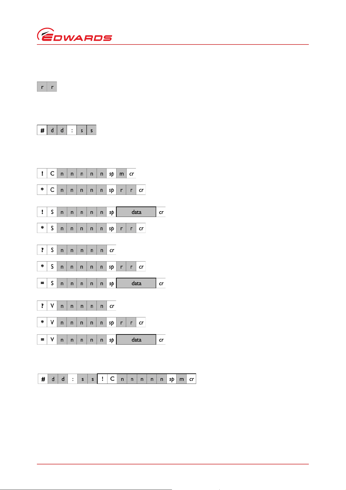
the same ID. In a message, the Object ID consists of 1 - 5 ASCII digits representing a number between 1 - 65535, as
shown below:
Data fields contain command codes, parameter values or response codes, and will vary in length and format according
to the message type. If there is more than one item in the data field, each item is separated by a semi colon(;).
Page 2 © Edwards Limited 2012. All rights reserved.
Edwards and the Edwards logo are trademarks of Edwards Limited.
Page 7
D397-30-880 Issue H
A returned response code consists of 1 or 2 characters representing a number between 0_99. A code of '0' always
means 'OK'. Other codes can be used to indicate various error conditions:
Where several items are linked together using multiple RS232 lines radiating from a hub, a 'multi-drop' identifier is
prefixed to each message. It is composed of a '#', followed by a 2 character Destination ID, a colon, and a 2 character
Source ID:
1.6 TIC serial protocol messages
GENERAL COMMAND
NORMAL (or ERROR) RESPONSE
Introduction
NORMAL (or ERROR) RESPONSE
1.6.1 TIC serial protocol - multi-drop prefix to a message
SETUP COMMAND
QUERY SETUP
ERROR RESPONSE
NORMAL RESPONSE
QUERY VALUE
ERROR RESPONSE
NORMAL RESPONSE
1.6.2 PC serial
This covers operations specific to the PC serial link covering control, monit orin g a n d se tup of all sections of the TIC
and the attached pumps.
Objects in the DX, nEXT or nXDS pump can be read via the TIC at their normal object ID and the TIC will pass the
messages on and return the reply, refer to DX, nEXT or nXDS requirements Section 1.3. Wait for the reply before
sending in another message even if the new message is for the TIC or 'other' pump.
© Edwards Limited 2012. All rights reserved. Page 3
Edwards and the Edwards logo are trademarks of Edwards Limited.
Page 8

D397-30-880 Issue H
Introduction
The following objects can be accessed via the PC serial comms:
Table 1 - Objects accessed via the PC serial comms
Object ID Object Operations Notes
800 + DX, nEXT and
nXDS objects
901 Node ?S
!S
902 TIC Status ?V T – see turbo state
0 – 98 Read multi-drop
B – see backing state
G – see gauge state
R – see relay state
Alert ID of 902
Highest priority level
in system
Routed, refer to DX, nEXT and nXDS pump
manual
Set multi-drop
Config type not needed
System status, depends on unit type –
TC
T;B;R1;R2;R3;Alert ID; priority
TIC
T;B;G1;G2;G3;R1;R2;R3;Alert ID; priority
NB just the state value
is returned between;
?S max 80 chars, typical 40Read system string - TICxxx; SW Ver; Ser
903 Unused
904 Turbo Pump ?V State 0 – 7 - see
Section 1.7.8
Alert – see
Section 1.7.3
Priority – see
Section 1.7.2
!C On =1
Off = 0
?S
!S
905 Turbo speed ?V Value 0.0 – 110.0% Turbo speed – value; alert ID; priority
?S
!S
see pump type list Read pump type
Master – object ID
gauge 1/2/3
Units type – 59, 66 see
snvt list
Setpoint –
volts 0.000 – 9.999,
pressure float.
Enable 1 = on, 0 = off
Delay 0 – 99 mins Read start delay
Times 1 – 30;
0 - 30 mins
IC
G1;G2;G3;R1;R2;R3;Alert ID; priority
IC6
G1;G2;G3;G4;G5;G6;R1;R2;R3;R4;R5;R6;
Alert ID; priority
e.g. TIC
4;4;0;11;0;0;4;0;0;0
Num; PIC SW ver
Config type not needed
Pump status – state; alert ID; priority
Turn pump on/off
Config type = 3
Read slave setup – master; units type; on
setpoint; off setpoint, enable
Write slave setup – master; units type; on
setpoint; off setpoint, enable
Config type = 4
Write start delay
Config type = 21
Read start fail time; droop fail time
Write start fail time; droop fail time
Config type not needed
Page 4 © Edwards Limited 2012. All rights reserved.
Edwards and the Edwards logo are trademarks of Edwards Limited.
Page 9

D397-30-880 Issue H
Table 1 - Objects accessed via the PC serial comms (continued)
Object ID Object Operations Notes
906 Turbo power ?V Value 0.0 – 300.0 w
(typ)
907 Turbo normal ?V State 0 = no, 4 = yes At normal speed – state; alert ID; priority
908 Turbo standby ?V 4 = in standby
0 = not in standby
!C 1 = set standby
0 = set not standby
909 Turbo cycle
time
910 Backing Pump ?V State 0 – 4 Pump status – state; alert ID; priority
911 Backing speed ?V Value 0.0 – 100.0% Backing speed - value; alert ID; priority
912 Backing power ?V Value 0.0 – 50.0 w
913 Gauge 1 ?V Value – pressure (see
?V V alue - 0-65535 hours Time period turbo has been on - value; state;
!C Turn pump on/off
?S
!S
?S
!S
!C Commands – see
see pump type list Read pump type
None = 0
On stop = 1
On 50% = 2
(typ)
gauge type) or voltage
0.000 to 11.000 volts.
Master – object ID
gauge 1/2/3 and turbo
speed.
Units type – 59, 66, 81
see snvt list.
Setpoints to suit units
type and master.
volts 0.000 – 9.999,
pressure float, pascals
speed 0 – 99.
Gauge type – see gauge
list
Gas type – see gas list.
Filter 1 = on,
0 = off.
0 = 1000
1 = 2000 mbar
Gauge name Read user gauge name - 4 characters 0-9, A-Z
command list
Turbo power – value; alert ID; priority
In standby mode
Set standby mode
alert ID; priority
Config type = 3
Read backing sequence options - none/on
stop/50%
Set backing sequence options
Config type = 70
Backing power - value; alert ID; priority
Gauge reading and state – value; units type;
state; alert ID; priority
Read slave setup – master; units type; on
setpoint; off setpoint, enable
Write slave setup – master; units type; on
setpoint; off setpoint, enable
Config type = 4
Read gauge type – e.g. AIMX
Config type = 5
Read gauge setup - gas type (volt); filter on/
off
Set gauge setup - gas type (volt); filter on/off
Config type = 7
Read ASG range
Set ASG range
Config type = 6
Set user gauge name
Config type = 68
Accept new gauge
On/off
Zero/calibrate/degas
Introduction
© Edwards Limited 2012. All rights reserved. Page 5
Edwards and the Edwards logo are trademarks of Edwards Limited.
Page 10

D397-30-880 Issue H
Introduction
Table 1 - Objects accessed via the PC serial comms (continued)
Object ID Object Operations Notes
914 Gauge 2 ?V
?S
!S
!C
915 Gauge 3 ?V
?S
!S
!C
916 Relay 1 ?V State 0 – 4 Relay state on/off - state; alert ID; priority
?S
!S
!C On = 1
917 Relay 2 ?V
?S
!S
918 Relay 3 ?V
?S
!S
919 PS
Temperature
920 Internal
Temperature
921 Analogue out ?V 0 – 255 Analogue out value - value; alert ID; priority
922 External vent
valve
923 Heater band ?V Value 0-2100 mins
924 External Air
Cooler
?V 273.0 – 400.0 celsius
?V see PS temperature TIC internal temperature value - value; alert
?S
!S
?V State 0 – 4 Vent valve state on/off – value; alert ID;
?S
!S
!C 0 = off, 1 = on On/off Heater band
?S
!S
?V State 0 – 4 Air cooler state on/off - value; alert ID;
?S
!S
see gauge 1 see gauge 1
see gauge 1 see gauge 1
Master – object ID
gauge 1/2/3
Units type – 59, 66, 81
see snvt list
Setpoints to suit units
type
Off = 0
see relay 1 see relay 1
see relay 1 see relay 1
offset by 274
i.e. freezing water =
274
Object ID gauge 1/2/3,
turbo speed
On stop = 0
On 50% = 1
State 0 – 4
Turbo slaved = 1
Permanent = 0
Read slave setup – master; units type; on
setpoint; off setpoint, enable
Set slave setup– master; units type; on
setpoint; off setpoint, enable
Config type not needed
Turn relay on/off
Power supply temperature value - value;
alert ID; priority
ID; priority
Read analogue out source
Set analogue out source
Config type not needed
priority
Read vent options – on stop/50%
Set vent options
Config type not needed
Heater band time, state on/off – value;
state; alert ID; priority
Read on time 0-35 hours
Set on time 0-35 hours
Config type not needed
priority
Read permanently on or turbo slaved
Write permanently on or turbo slaved
Config type not needed
Page 6 © Edwards Limited 2012. All rights reserved.
Edwards and the Edwards logo are trademarks of Edwards Limited.
Page 11

Table 1 - Objects accessed via the PC serial comms (continued)
Object ID Object Operations Notes
925 Display
contrast
926 Configuration
Operations
928 Lock ?S
929 Pressure Units ?S
930 PC comms ?S
931 Default screen ?S
?S
!S
!C see command list Default TIC
!S
!S
!S
!S
-5 – 15 Read contrast setting
Set contrast setting
Config type not needed
Default Turbo send to DX or nEXT pump
Load config to Turbo (DX or nEXT)
Load config from Turbo (DX or nEXT)
?S-Locked = 1
Released = 0
!S-see config list
?S-Locked = 1
Released = 0
!S-see config list
kPa = 1
mbar = 2
Torr = 3
232 = 0
485 = 1
All = 0
Three gauges = 1
Gauge 1 = 2
Gauge 2 = 3
Gauge 3 = 4
Turbo only = 5
One gauge = 6
Six gauges = 7
Turbo + one gauge = 8
Possible IDs are - 913,
914, 915, 934, 935,
936 and 0 = none
As above Read three gauge order
Lock/release config setup
Lock/release front panel
Read display pressure Units – kPascal/mbar/
Torr
Set display pressure Units – kPascal/mbar/
Torr
Config type not needed
Read PC comms to RS232/RS485
Set PC comms to RS232/RS485
Config type not needed
Read default screen
Set default screen
Config type 15
Options 2,3,4 are only available to
D39700640F and earlier.
Options 6,7 are only available to D397 00640G
and later.
TC - option 5 only
TIC - option 0,1,2,3,4,5,6
IC - options 1,6
IC6 - options 1,6,7
Read one gauge order
Set one gauge order
Config type 71
S931 71;Position 1 ID;Pos 2 ID;Pos 3 ID;
Pos 4 ID; Pos 5 ID;Pos 6 ID
Gauge IDs can be in any order and can be
repeated.
0 (zero) ID entry means don’t show this
position.
Set three gauge order
Config type 72
S931 72;Position 1 ID;Pos 2 ID; Pos 3 ID;
Pos 4 ID;Pos 5 ID;Pos 6 ID
Gauge IDs can be in any order and can be
repeated.
0 (zero) ID entry means don’t show this
position but there must be a minimum of
three non-zero entries.
D397-30-880 Issue H
Introduction
© Edwards Limited 2012. All rights reserved. Page 7
Edwards and the Edwards logo are trademarks of Edwards Limited.
Page 12

D397-30-880 Issue H
Introduction
Table 1 - Objects accessed via the PC serial comms (continued)
Object ID Object Operations Notes
932 Fixed/Float
ASG
933 System (TIC
and TC only)?S!S
?S
!S
Float = 1
Fixed = 0
0 = no
1 = yes
Read Float/fixed display (ASG)
Write Float/fixed display (ASG)
Config type not needed
Read/write System On/Off setup
Config type not needed
The message consists of sections of Object
ID; system on; system off.
Any number of whole sections can be sent up
to the maximum of 12. Invalid object IDs will
be ignored. You can send just the sections
you wish to alter e.g. !S933 915;1;1;910;1;0cr
The actual structures for each kind of unit
are shown below. ?S answers will be in this
order and return all relevant entries.
TIC
Turbo 904;on;off;
Back 910;on;off;
Gauge1 913;on;off;
Gauge2 914;on;off;
Gauge3 915;on;off;
Relay1 916;on;off;
Relay2 917;on;off;
Relay3 918;on;off
e.g. = S933 904;0;1;910;1;0;913;0;0;914;0;
915;0;0;916;1;1;917;0;0;918;0;0cr
TC
Turbo 904;on;off;
Back 910;on;off;
Relay1 916;on;off;
Relay2 917;on;off;
Relay3 918;on;off;
e.g. = S933 904;0;1;910;1;0;916;1;1;917;0;0;
918;0;0cr
Recommend read/modify/write sequence to
reduce errors.
!C 0 = off, 1 = on On/off System
System on will turn on objects marked with a
1 in the setup on field
System off will turn off objects marked with
a 1 in the setup off field
?V State 0 - 4 System status - state; alert ID; priority
Page 8 © Edwards Limited 2012. All rights reserved.
Edwards and the Edwards logo are trademarks of Edwards Limited.
Page 13

Table 1 - Objects accessed via the PC serial comms (continued)
Object ID Object Operations Notes
934 Gauge 4 ?V Value - pressure (see
gauge type) or voltage
0.000 to 11.000 volts.
?S
!S
Master - object ID
gauge 1/2/3 and turbo
speed.
Units type - 59, 66, 81
see snvt list. Setpoints
to suit units type and
master.
volts 0.000 - 9.999,
pressure float,
speed 0 - 99.
Gauge type - see gauge
list
Gas type - see gas list.
Filter - 1 = on, 0 = off.
0 = 1000
1 = 2000 mbar
Gauge name Read user gauge name - 4 characters 0-9,
0 = 0.05
1 = 0.1
2 = 0.2
3 = 1
....
10 = 2000
Gauge reading and state - value; units type;
state; alert ID; priority
Read slave setup - master; units type; on
setpoint; off setpoint, enable
Write slave setup - master; units type; on
setpoint; off setpoint, enable
Config type = 4
Read gauge type - e.g. AIMX
Config type = 5
Read gauge setup - gas type (volt);
filter on/off
Set gauge setup - gas type (volt);
filter on/off
Config type = 7
Read ASG range
Set ASG range
Config type = 6
A-Z
Set user gauge name
Config type = 68
Read CapMan setup - range;units
Write CapMan setup - range;units
Config type = 73
D397-30-880 Issue H
Introduction
2 = mBar
3 = Torr
© Edwards Limited 2012. All rights reserved. Page 9
Edwards and the Edwards logo are trademarks of Edwards Limited.
Page 14

D397-30-880 Issue H
Introduction
Table 1 - Objects accessed via the PC serial comms (continued)
Object ID Object Operations Notes
934 Gauge 4 ?S
!S
!C Commands - see
935 Gauge 5 See Gauge 4 See Gauge 4
936 Gauge 6 See Gauge 4 See Gauge 4
937 Relay 4 ?V
?S
!S
938 Relay 5 ?V
?S
!S
939 Relay 6 ?V
?S
!S
940 Gauge Values ?V Position 1-6.
Filament
1 = 1
2 = 2
Head
1 = A
2 = B
Emission
0 = Auto
1 = 100uAmp
2 = 1 mAmp
3 = 10 mAmp
Restrike
0 = off
1 = on
Constant1
0.020 to 0.480
Constant2
0.020 to 0.480
command list
See Relay 1 See Relay 1
See Relay 1 See Relay 1
See Relay 1 See Relay 1
Value - pressure (see
gauge type) or voltage
0.000 to 11.000 volts.
Read IGC setup
Write IGC setup
Filament;head;emission;restrike;constant1;
constant2
Config type = 74
e.g.
!S913 74;1;1;0;0;0.1;0.1
Accept new gauge
On/off
Zero/calibrate/degas
For each attached gauge
<Position byte>;<Gauge value>;
Examples
Reply for 1 gauge connected at position 2
=V940 2;3.9441e+02;
Reply for 3 gauges connected at p ositions 2, 3
and 5 with gauge 2 in voltage mode and
gauge 5 not ON (e.g. OFF, error, striking etc)
=V940 2;6.546;3;2.7245e-04;5; 9.9000e+09;
Note: The pump shall accept the wildcard multi-drop address 99.
The pump shall accept the wildcard object ID 0 for a ?S and return information from the TIC Status object
902.
The following are examples of abbreviations and codings, with their meanings, which appear in subsequent
paragraphs.
Page 10 © Edwards Limited 2012. All rights reserved.
Edwards and the Edwards logo are trademarks of Edwards Limited.
Page 15
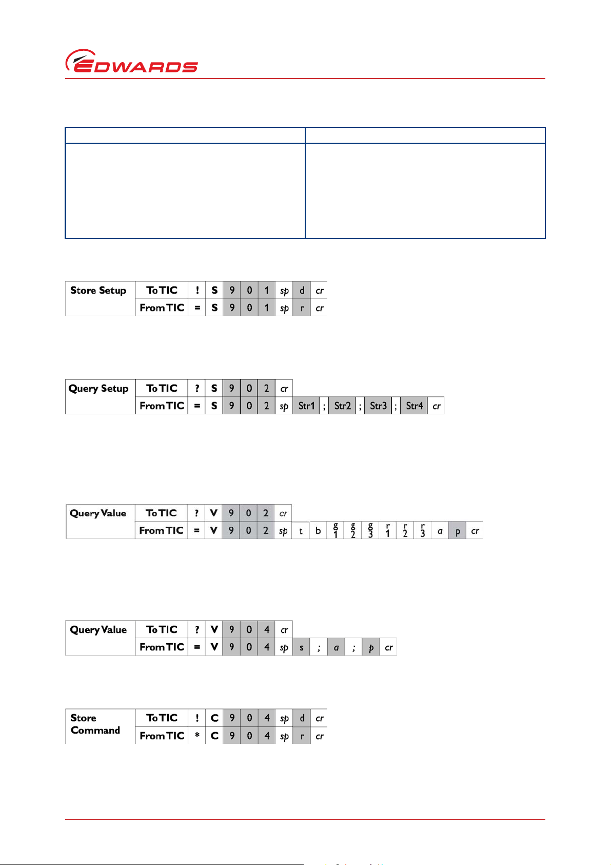
Table 2 - Abbreviations
Abbreviation Meaning
r returned error code – see Table 3
String may have several ASCII characters
d decimal ASCII character
h hexadecimal ASCII character
ck checksum (1 byte)
cr carriage return
1.6.2.1 Node object 901
where d is the multi-drop address to be stored in EEPROM.
1.6.2.2 Node object 902
D397-30-880 Issue H
Introduction
Query setup returns a data string in the following format:
TIC;Dxxxxxxxx;serial number;PIC s/w ver
where 'TIC' is a fixed string for this pump, Dxxxxxx is the software version number fixed by the software, serial
number is a string loaded during production, PIC s/w ver is the PIC software version.
System state of key items on the TIC, state value from Turbo, backing, gauge 1, gauge 2, gauge 3, relay 1, relay 2,
relay 3, alert ID of object 902 and highest priority on the TIC.
1.6.2.3 Turbo pump object 904
where s is the state of the pump, a is the alert ID and p is the priority. Number of characters per parameter is as
required to represent the value.
where d is 0 = pump off, 1 = pump on.
© Edwards Limited 2012. All rights reserved. Page 11
Edwards and the Edwards logo are trademarks of Edwards Limited.
Page 16

D397-30-880 Issue H
Introduction
where 3 is the config type and p is the pump type.
where 4 is the config type, m is the master object, p is pressure '59' or voltage '66', n is the on setpoint, f is the off
setpoint and e is enabled '1' or disabled '0' e.g.
=S904 913;59;5.1e-2;4.9e-1;1
=S904 914;66;3.62;4.34;1.
1.7 Additional information
1.7.1 Serial comms response codes (*Cnnn x, *S, *V)
Value Meaning
0 no error
1 Invalid command for object ID
2 Invalid query/command
3 Missing parameter
4 Parameter out of range
5 Invalid command in current state - e.g. serial command
6 Data checksum error
7 EEPROM read or write error
8 Operation took too long
9 Invalid config ID
1.7.2 Priority
OK = 0
warning = 1
alarm = 2/3
Table 3 - Serial comms response codes
to start or stop when in parallel control mode
1.7.3 Alert ID
No Alert = 0
ADC Fault = 1
ADC Not Ready = 2
Page 12 © Edwards Limited 2012. All rights reserved.
Edwards and the Edwards logo are trademarks of Edwards Limited.
Page 17

Over Range = 3
Under Range = 4
ADC Invalid = 5
No Gauge = 6
Unknown = 7
Not Supported = 8
New ID = 9
Over Range = 10
Under Range = 11
Over Range = 12
Ion Em Timeout = 13
Not Struck = 14
Filament Fail = 15
Mag Fail = 16
Striker Fail = 17
Not Struck = 18
Filament Fail = 19
Cal Error = 20
Initialising = 21
Emission Error = 22
Over Pressure = 23
ASG Cant Zero = 24
D397-30-880 Issue H
Introduction
RampUp Timeout = 25
Droop Timeout = 26
Run Hours High = 27
SC Interlock = 28
ID Volts Error = 29
Serial ID Fail = 30
Upload Active = 31
DX Fault = 32
Temp Alert = 33
SYSI Inhibit = 34
Ext Inhibit = 35
Temp Inhibit = 36
No Reading = 37
No Message = 38
NOV Failure = 39
Upload Timeout = 40
Download Failed = 41
No Tube = 42
Use Gauges 4-6 = 43
Degas Inhibited = 44
IGC Inhibited = 45
Brownout/Short = 46
Service due =47
© Edwards Limited 2012. All rights reserved. Page 13
Edwards and the Edwards logo are trademarks of Edwards Limited.
Page 18

D397-30-880 Issue H
Introduction
1.7.4 SNVT values
VOLTAGE 66 - float
PRESSURE 59 - float (Pascals only)
PERCENT 81
Note: Pressure values used in the configuration setups and in the logging will be in Pascals. They are not stored
or displayed in the selected units.
1.7.5 Command list
Device Off = 0 //general off/on
Device On = 1
Gauge Off = 0
Gauge On = 1
Gauge New_Id = 2
Gauge Zero = 3
Gauge Cal = 4
Gauge Degas = 5
Load Defaults = 576
Upload = 0 //to TIC
Download = 1 //from TIC
1.7.6 State
Off State = 0
Off Going On State = 1
On Going Off Shutdown State = 2
On Going Off Normal State = 3
On State = 4
1.7.7 Active gauge states
Gauge Not connected = 0
Gauge Connected = 1
New Gauge Id = 2
Gauge Change = 3
Gauge In Alert = 4
Off = 5
Striking = 6
Initialising = 7
Calibrating = 8
Zeroing = 9
Degassing = 10
On = 11
Inhibited = 12
Page 14 © Edwards Limited 2012. All rights reserved.
Edwards and the Edwards logo are trademarks of Edwards Limited.
Page 19

1.7.8 Full pump states
TIC’s representation of an attached pump’s state.
Stopped = 0
Starting Delay = 1
Accelerating = 5
Running = 4
Stopping Short Delay = 2
Stopping Normal Delay = 3
Fault Braking = 6
Braking = 7
1.7.9 Gas types
Nitrogen = 0
Helium = 1
Argon = 2
Carbon Dioxide = 3
Neon = 4
Krypton = 5
Voltage = 6
D397-30-880 Issue H
Introduction
1.7.10 Gauge types
Unknown Device = 0
No Device = 1
EXP_CM = 2
EXP_STD = 3
CMAN_S = 4
CMAN_D = 5
TURBO = 6
APGM = 7
APGL = 8
APGXM = 9
APGXH = 10
APGXL = 11
ATCA = 12
ATCD = 13
ATCM = 14
WRG = 15
AIMC = 16
AIMN = 17
AIMS = 18
AIMX = 19
AIGC_I2R = 20
AIGC_2FIL = 21
ION_EB = 22
AIGXS = 23
USER = 24
ASG = 25
© Edwards Limited 2012. All rights reserved. Page 15
Edwards and the Edwards logo are trademarks of Edwards Limited.
Page 20

D397-30-880 Issue H
Introduction
1.7.11 Pump types
No Pump = 0
EXDC Pump = 1
EXT75DX Pump = 3
EXT255DX = 4
Mains Backing Pump = 8
Serial Pump = 9 //temporary until serial comms receives ID from pump
nEXT - 485 = 10 //TIC only supports this in parallel form
nEXT - 232 = 11
nXDS = 12
Not yet identified = 99
Page 16 © Edwards Limited 2012. All rights reserved.
Edwards and the Edwards logo are trademarks of Edwards Limited.
Page 21

Index
D397-30-880 Issue H
Index
A
Abbreviations ............................................ 11
Active gauge states .....................................14
Additional information
Alert ID .................................................... 12
................................. 12
C
Command list ............................................ 14
Commands
Communications timings
..................................................1
.................................2
D
DX, nEXT and nXDS pumps ...............................2
F
Full pump states .........................................15
G
Gas types .................................................15
Gauge types .............................................. 15
General command .........................................3
I
Introduction ................................................1
Setup command
SNVT values .............................................. 14
State ...................................................... 14
...........................................3
T
TIC serial protocol - multi-drop prefix to a message 3
TIC serial protocol messages ............................3
M
Message basics .............................................1
O
Object IDs ..................................................2
Objects accessed via the PC serial comms
............4
P
PC serial ....................................................3
....................................................12
Priority
Pump types
...............................................16
Q
Queries ......................................................1
Query setup ................................................3
Query value ................................................3
R
Responses ...................................................2
S
Scope ........................................................1
Serial comms response codes (*Cnnn x, *S, *V) ..... 12
........................................................2
Setup
© Edwards Limited 2012. All rights reserved. Page 17
Edwards and the Edwards logo are trademarks of Edwards Limited.
Page 22

D397-30-880 Issue H
This page has been intentionally left blank.
Page 18 © Edwards Limited 2012. All rights reserved.
Edwards and the Edwards logo are trademarks of Edwards Limited.
 Loading...