

Page 1
Instruction Manual
GXS/CXS Profibus Module
D397-53-880
Issue C
Description Item Number
GXS/CXS Profibus Module D397-53-000
Original Instructions
Page 2

Declaration of Conformity
We, Edwards,
Innovation Drive,
Burgess Hill,
West Sussex,
RH15 9TW, UK
declare under our sole responsibility, as manufacturer and person within the EU
authorised to assemble the technical file, that the product(s)
GXS/CXS Profibus Module 0397-53-000
to which this declaration relates is in conformity with the followin g standard(s) or
other normative document(s)
EN61326-1:2013 Electrical equipment for measurement, control and
(Class B Emissi ons, laboratory Use. EMC requirements. General requirements
Industrial Immunity)
and fulfils all the relevant provisions of
2014/30/EU Electromagnetic Compatibility (EMC) Directive
2011/65/EU Restriction of Certain Hazardous Substances (RoHS) Directive
16.08.2016, Eastbourne
Larry Marini, Senior Technical Manager
This product has been manufactured under a quality management system certified to ISO 9001:2008
Date and Place
P200-03-880 Issue C
Page 3
P200-10-086
Issue A
Material Declaration
In accordance with the requirements of the Chinese regulatory requirement on the Ma nagement Methods for the
Restriction of the Use of Hazardous Substances in Electrical and Electronic Products Order No. 32 (also known as
‘China RoHS2’) and SJ/T 11364 Marking for the Restricted Use of Hazardous Substances in Electronic and Electrical
Products:
Product Product Label Meaning
This product contains hazardous substances in at
least one of the homogeneous materials used
which are above the limit requirement in GB/T
D39753000 GXS/CXS Profibus Module
部件名称
Part name
印刷电路组件 (PCA)
Printed Circuit
Assembly (PCA)
电缆/电线/连接器
Cable/wire/connector
机械部件
Mechanical Components
铅
Lead
(Pb)
Mercury
(Hg)
X O X
X O
X O
材料成分声明
Materials Content Declaration
Hazardous Substances
汞
镉
Cadmium
(Cd)
O O O O
O O O O
26572 as detailed in the declaration table below.
These parts can safely be used for the
environmental protection use period as
indicated.
有害物质
六价铬
Hexavalent
Chromium
(Cr VI)
多溴联苯
Polybrominated
biphenyls (PBB)
多溴二苯醚
Polybrominated
diphenyl ethers
(PBDE)
O O O
O: 表示该有害物质在该部件的所有均质材料中的含量低于 GB/T 26572 标准规定的限量要求。
O: Indicates that the hazardous substance contained in all of the homogeneous materials for this part is
below the limit requirement in GB/T 26572.
X: 表示该有害物质在该部件的至少一种均质材料中的含量超出 GB/T26572 标准规定的限量要求。
X: Indicates that the hazardous substance contained in at least one of the homogeneous materials used for
this part is above the limit requirement of GB/T26572.
NOTE:TheseproductsareEURoHScompliant,thefollowingExemptionsapply:
6(b)Leadasanalloyingelementinaluminiumcontainingupto0.4%byweight
6(c)Copperalloycontainingupto4%leadbyweight
7(a)Leadininhighmeltingtemperaturetypesolder(i.e.leadbasedalloyscontaining85%byormore)
7(b) Leadin solders for servers, storage andstorage array systems, network infrastructureequipmentfor switching, signalling,
transmission,andnetworkmanagementfortelecommunications
7(c)I Electrical andelectronic componentscontaining leadina glassor ceramic otherthandielectric ceramicin capacitors, e.g.
piezoelectronicdevices,orina
glassorceramicmatrixcompound
7(c)IILeadindielectricceramicincapacitorsforaratedvoltageof125VACor250VDCorhigher
8(b)Cadmiumanditscompoundsinelectricalcontacts
15Leadinsolderstocompleteaviableelectricalconnectionbetween semiconductordieandcarrierwithinintegratedcircuitflip
chippackages
34Leadincermet‐basedtrimmerpotentiometerelements
Page 4

This page has been intentionally left blank.
Page 5

D397-53-880 Issue C
Contents
Section Page
1 Introduction .......................................................................................1
1.1 Scope and definitions ...................................................................................................1
1.2 Outline description ...................................................................................................... 2
2 Technical data ....................................................................................3
2.1 Mechanical data .......................................................................................................... 3
2.2 Operating and storage data ............................................................................................ 3
2.3 Electrical data ............................................................................................................ 3
2.3.1 D.C. Power connector ................................................................................................... 3
2.3.2 Profibus connector ...................................................................................................... 4
2.3.3 RS232 Connector ......................................................................................................... 5
2.3.4 Front panel USB connector ............................................................................................. 5
3 Installation ............................................... ................................... .......7
3.1 Unpack and inspect ...................................................................................................... 7
3.2 Fitting the module to a GXS pump .................................................................................... 7
3.3 Fitting the module to a CXS pump .................................................................................... 8
3.4 Electrical connections ................................................................................................... 8
3.5 Profibus network connection .......................................................................................... 8
Contents
4 Operation ..........................................................................................9
4.1 Profibus system information ........................................................................................... 9
4.2 Quick start set up instructions ......................................................................................... 9
4.3 Front panel display ...................................................................................................... 9
4.4 Address set-up ...........................................................................................................10
4.5 Baud-rate ................................................................................................................12
4.6 Software format ........................................................................................................12
4.6.1 Parameterisation ........................................................................................................13
4.6.2 Configuration ............................................................................................................13
4.6.3 Diagnostics description ................................................................................................14
4.6.4 Data exchange values ..................................................................................................14
4.7 Software modules .......................................................................................................15
4.7.1 Module 990 - Pump Family ............................................................................................17
4.7.2 Module 991 - Pump Serial Number ...................................................................................17
4.7.3 Module 110 - Remote/Local State ....................................................................................17
4.7.4 Module 992 - Alert Status ..............................................................................................17
4.7.5 Module 11 - Pump Control .............................................................................................18
4.7.6 Module 14 - DP Run Hours .............................................................................................19
4.7.7 Module 20 - DP Number of Starts .....................................................................................19
4.7.8 Module 21 - DP Time to Stop ..........................................................................................19
4.7.9 Module 3 - DP Current ..................................................................................................19
4.7.10 Module 4 - DP Power ...................................................................................................19
4.7.11 Module 184 - DP Speed Absolute .....................................................................................19
4.7.12 Module 994 - DP Speed Relative ......................................................................................19
4.7.13 Module 699 - DP Speed Demand ......................................................................................20
4.7.14 Module 55 - DP Body Temperature ...................................................................................20
4.7.15 Module 63 - Pump Internal Temperature ...........................................................................20
4.7.16 Module 12 - MB Override ...............................................................................................20
4.7.17 Module 46 - Gas Ballast ................................................................................................20
4.7.18 Module 47 - Inlet Pu rge ................................................................................................21
4.7.19 Module 7 - MB Current .................................................................................................21
cg/0060/07/16
© Edwards Limited 2016. All rights reserved. Page i
Edwards and the Edwards logo are trademarks of Edwards Limited.
Page 6

D397-53-880 Issue C
Contents
4.7.20 Module 8 - MB Power ...................................................................................................21
4.7.21 Module 174 - MB Speed Absolute .....................................................................................21
4.7.22 Module 995 - MB Speed Relative ......................................................................................22
4.7.23 Module 698 - MB Speed Demand ......................................................................................22
4.7.24 Module 54 - MB Body Temperature ...................................................................................22
4.7.25 Module 34 - Nitrogen Flow Switch ....................................................................................22
4.7.26 Module 68 - Active Utility Control ....................................................................................22
4.7.27 Module 39 - Exhaust Pressure .........................................................................................22
4.7.28 Module 53 - Active Gauge .............................................................................................23
4.7.29 Module 52 - Water Flow Rate .........................................................................................23
4.7.30 Module 161 - Gate Valve ...............................................................................................23
4.7.31 Module 323 - Pump Warm-up .........................................................................................23
4.7.32 Module 328 - Pump Good ..............................................................................................23
4.7.33 Module 331 - DP Clean Control .......................................................................................24
4.7.34 Module 332 - Auxiliary Active (Strain) Gauge Pressure ...........................................................24
4.7.35 Module 333 - Inter-pump Temperature ..............................................................................24
4.7.36 Module 334 - Process Pressure ........................................................................................24
4.7.37 Module 993 - Profibus Software Version .............................................................................24
4.7.38 Module 1 - Winterisation ...............................................................................................24
4.7.39 Module 322 - Solvent Soak .............................................................................................24
4.7.40 Module 346 - DP 2nd Speed Reference ..............................................................................25
4.7.41 Module 316 - PID Pressure Control ...................................................................................25
4.7.42 Module 344 - Pressure Demand .......................................................................................25
4.7.43 Module 313 - MB 2nd Speed Reference ..............................................................................25
4.7.44 Module 812 - pXH Override. ...........................................................................................25
4.7.45 Module 14 - pXH Run Hours ............................................................................................25
4.7.46 Module 818 - pXH Number of Starts ..................................................................................26
4.7.47 Module 820 - pXH Current .............................................................................................26
4.7.48 Module 821 - pXH Power ...............................................................................................26
4.7.49 Module 823 - pXH Speed Absolute ....................................................................................26
4.7.50 Module 996 - pXH Speed Relative ....................................................................................26
4.7.51 Module 697 - pXH Speed Deman d ....................................................................................26
4.7.52 Module 813 - pXH Body Temperature ................................................................................26
4.7.53 Module 268 - CXS P2 or EMS ...........................................................................................26
4.7.54 Module 270 - CXS Exhaust Valve ......................................................................................26
4.7.55 Module 271 - CXS Exhaust Temperature Warning ..................................................................27
4.7.56 Module 272 - CXS Exhaust Temperature Alarm .....................................................................27
4.7.57 Module 273 - CXS Exhaust Pressure Warning .......................................................................27
4.7.58 Module 274 - CXS Exhaust Pressure Alarm ..........................................................................27
4.7.59 Module 275 - CXS Body Thermal Snap Switch .......................................................................27
4.7.60 Module 276 - CXS Motor Thermal Snap Switch .....................................................................27
4.7.61 Module 277 - CXS Flame Arrestor .....................................................................................27
4.7.62 Module 279 - CXS MB Motor Run ......................................................................................27
4.7.63 4.7.60 Module 280 - CXS MB Motor Thermistor .....................................................................27
4.7.64 Module 281 - CXS MB Water Flow .....................................................................................27
4.7.65 Module 282 - CXS N2 Flow .............................................................................................28
4.7.66 Module 285 - CXS MB Outlet Pressure ................................................................................28
4.7.67 Module 286 - CXS EXD Water Level ...................................................................................28
4.7.68 Module 287 - CXS EXD Solvent L evel .................................................................................28
4.7.69 Module 288 - CXS Process Interlock Input ...........................................................................28
4.7.70 Module 150 - CXS Spare ................................................................................................28
4.7.71 Module 267 - CXS DP Body .............................................................................................28
4.7.72 Module 289 - CXS Bypass Valve .......................................................................................28
4.7.73 Module 1011 - CXS On Process Warning .............................................................................29
4.7.74 Module 1012 - CXS On Process Cold ..................................................................................29
5 Maintenance ..................................................................................... 30
5.1 Fault finding .............................................................................................................30
6 Storage and disposal .............................. ..... ..... ..... ..... ......................... 31
Page ii © Edwards Limited 2016. All rights reserved.
Edwards and the Edwards logo are trademarks of Edwards Limited.
Page 7

D397-53-880 Issue C
6.1 Storage ...................................................................................................................31
6.2 Disposal ...................................................................................................................31
7 Spares and accessories ......................................................................... 32
7.1 Introduction .............................................................................................................32
For return of equipment, complete the HS Forms at the end of this manual.
Illustrations
Figure Page
1 Pin connections for the 2-way Power Connector ................................................................... 3
2 Pin connections for 9-way ‘D’ type socket ........................................................................... 4
3 Pin connections for 9-way ‘D’ type plug ............................................................................. 5
4 Profibus mounted on pump rear ....................................................................................... 7
5 Profibus module rear connections .................................................................................... 8
6 Profibus front panel display ............................................................................................ 9
Contents
Tables
Table Page
1 Pin connections for 9-way ‘D’ type socket ........................................................................... 4
2 Pin connections for 9-way ‘D’ type plug ............................................................................. 5
3 Component checklist .................................................................................................... 7
4 Front panel symbols and their functions ............................................................................10
5 Address switch settings ................................................................................................10
6 Summary of software modules ........................................................................................15
7 Fault finding guide ......................................................................................................30
© Edwards Limited 2016. All rights reserved. Page iii
Edwards and the Edwards logo are trademarks of Edwards Limited.
Page 8

D397-53-880 Issue C
This page has been intentionally left blank.
Page iv © Edwards Limited 2016. All rights reserved.
Edwards and the Edwards logo are trademarks of Edwards Limited.
Page 9

D397-53-880 Issue C
CAUTION
WARNING
1Introduction
1.1 Scope and definitions
This manual provides instal lation, operat ion and mai ntenance instructions for Edwards GXS and CXS pump Profibus
Modules. You must use the Module as specified in this manual.
Read this manual before you install and operate the Module. Important safety information is highlighted as WARNING
and CAUTION instructions; you must obey these instructions. The use of WARNINGS and CAUTIONS is defined below.
Warnings are given where failure to observe the instruction could result in injury or death to
people.
Cautions are given where failure to observe the instruction could result in damage to the equipment, associated
equipment and process.
Introduction
Throughout this manual, page, figure or title numbers are sequential.
The following labels appear on the module:
Warning - refer to accompanying documentation.
Edwards offer European customers a recycling service.
© Edwards Limited 2016. All rights reserved. Page 1
Edwards and the Edwards logo are trademarks of Edwards Limited.
Page 10

D397-53-880 Issue C
WARNING
WARNING
WARNING
Introduction
1.2 Outline description
Edwards take no responsibility for damage or injury caused by improper use of the equipment.
This equipment provides remote control of an Edwards pump. You must refer to the safety
information in the pump instruction manual.
This unit should not be relied upon for safety related functions.
The GXS and CXS Profibus Module provides a Profibus DP V0 slave interface for Ed wards GXS and CXS pumps. The
module communicates with the pump using the RS232 interface. Commands received from the Profibus network are
relayed to the pump. Data from the pump is stored in the module and transmitted over the Profibus network when
requested. The pumps provide the DC power for the module. The front panel of the module has four LEDs which
indicate the status of the module and the Profibus network. The Profibus slave address is set using rotary switches.
The back panel of the module has a 9-way 'D' connector for the Profibus network, a 9-way 'D' connector for the RS232
link to the pump and a power connector.
Page 2 © Edwards Limited 2016. All rights reserved.
Edwards and the Edwards logo are trademarks of Edwards Limited.
Page 11
2Technical data
WARNING
2.1 Mechanical data
Weight 0.28 kg
Dimensions 129 x 30.5 x 117 mm
Refer to Section 3.2 for installed dimensions and panel cut-out.
2.2 Operating and storage data
Ambient operating temperature 0°C to 40°C
Humidity Max 90% RH non-condensing
Maximum altitude 2000 m
IP rating IP30 - indoor use only
Ambient storage temperature -30°C to 70°C
D397-53-880 Issue C
Technical data
2.3 Electrical data
Do not exceed the maximum supply voltage. Excessive supply voltage will cause permanent
damage to the control electronics and may result in a mechanical hazard in some failure
conditions.
Electrical supply 9 V d.c. to 52 V d.c.
Power consumption 5 W max. Switch on surge 500 mA max.
Fuse No internal fuse
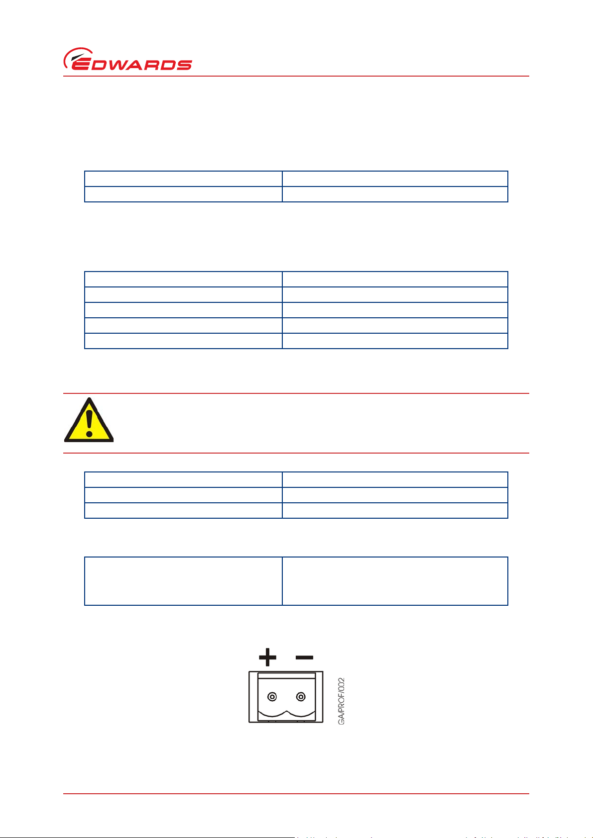
2.3.1 D.C. Power connector
Connector type 2 Way Receptacle. Mating part is cable-mount
Terminal Block. Suitable parts include: Phoenix MSTB
2.5/2-G-5.08; Weidmuller BLZ 5.08/2; Amp 796634-2;
IMO 21.950/2 (Refer to Figure 1).
Figure 1 - Pin connections for the 2-way Power Connector
© Edwards Limited 2016. All rights reserved. Page 3
Edwards and the Edwards logo are trademarks of Edwards Limited.
Page 12
D397-53-880 Issue C
Technical data
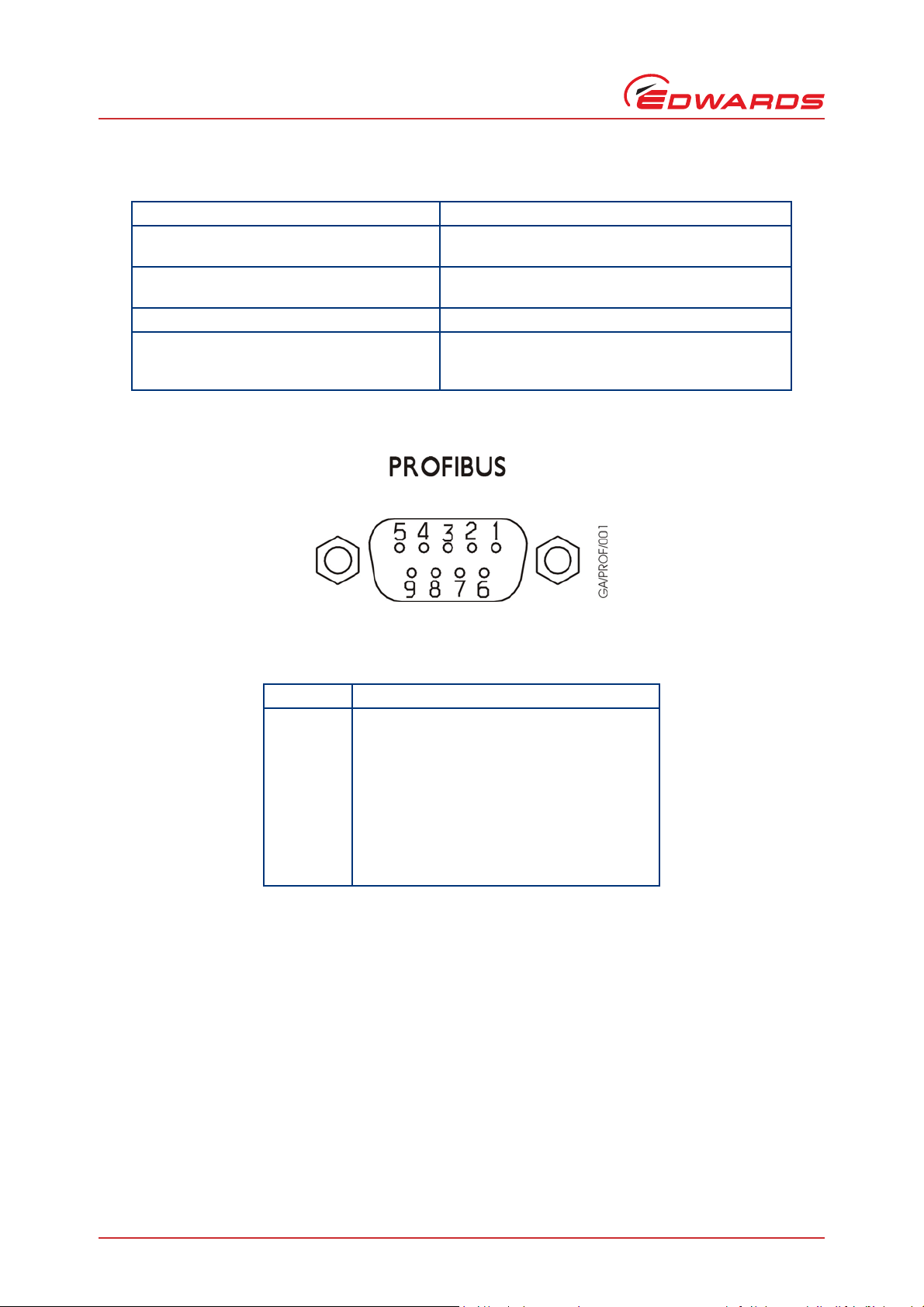
2.3.2 Profibus connector
Connector type 9-way ‘D’ type socket (Refer to Figure 2)
Profibus Data signals Electrically compliant with RS485 specification.
Profibus Power Supply 10 mA supply (protected) for external terminator
Chassis For Profibus cable screen connection
Repeater control signal Digital signal, nominally 0-5 V but with series 340 ohm
Figure 2 - Pin connections for 9-way ‘D’ type socket
Isolated from chassis.
resistors if required.
resistor. High = module transmitting. Low = Receiving
or Idle.
Table 1 - Pin connections for 9-way ‘D’ type socket
Pin Allocation
1
2
3
4
5
6
7
8
9
Shell
Chassis (box)
Not connected
Profibus Data + (B)
Control Signal for Repeater
Profibus Data reference (isolated)
Profibus 5V output (isolated)
Not connected
Profibus Data - (A)
Not connected
Chassis (box)
Page 4 © Edwards Limited 2016. All rights reserved.
Edwards and the Edwards logo are trademarks of Edwards Limited.
Page 13

2.3.3 RS232 Connector
Connector type 9-way ‘D’ type Plug (Refer to Figure 3)
For connection to serial comms port of SCU-750/1500
Controller only.
RS232 protocol 9600 baud, 1 stop bit, 8 data bits, no parity
Figure 3 - Pin connections for 9-way ‘D’ type plug
Table 2 - Pin connections for 9-way ‘D’ type plug
D397-53-880 Issue C
Technical data
Pin Allocation
1
2
3
4
5
6
7
8
9
Shell
Not connected
RS232 receive
RS232 transmit
Not connected
RS232 common
Not connected
Not connected
Not connected
Not connected
Chassis (box)
2.3.4 Front panel USB connector
Connector type USB Micro-B socket
Function Software upgrade by Edwards service personnel only
© Edwards Limited 2016. All rights reserved. Page 5
Edwards and the Edwards logo are trademarks of Edwards Limited.
Page 14

D397-53-880 Issue C
This page has been intentionally left blank.
Page 6 © Edwards Limited 2016. All rights reserved.
Edwards and the Edwards logo are trademarks of Edwards Limited.
Page 15

D397-53-880 Issue C
3 Installation
3.1 Unpack and inspect
Remove all of the packaging material and check the Module. If the Mod ule is damaged, follow the Edwards return of
equipment procedures that are laid out in the back of this manual. Do not use the Module if it is damaged.
Check that your package contains the items that are listed in Table 3. If any of the s e it ems are missing, notify your
supplier in writing within three days. If the Module is not to be used immediately, store the Module in suitable
conditions as described in Section 6.1.
Table 3 - Component checklist
Quantity Description Check()
1Module
1 Instruction Manual
1 Cable for connection between pump PDT port and Profibus
Module
4 Mounting screws (2-off M2.5, 2-off M5)
1 Mounting bracket
1 CD (includes GSD file)
Installation
3.2 Fitting the module to a GXS pump
Fit the Mounting Bracket to the M5 captive nuts in the rear of the pump using the M5 combined bolts and washers
provided. The bracket fits upright, essentially above the exhaust with the mounting holes separated by 125 mm
vertically.
Fit the Profibus module to the bracket using the M2.5 mounting hardware provided. See Figure 4 below.
Figure 4 - Profibus mounted on pump rear
© Edwards Limited 2016. All rights reserved. Page 7
Edwards and the Edwards logo are trademarks of Edwards Limited.
Page 16

D397-53-880 Issue C
WARNING
Installation
3.3 Fitting the module to a CXS pump
To fit the module to the CXS pump, contact Edwards.
3.4 Electrical connections
When installing the module ensure that the cables are laid out and secured in a manner that will
not create a trip hazard.
The Profibus module should not be connected to a pump when the pump or tool are "On Process".
The Profibus Module uses the pump's rear (system) PDT port (a 5-way XLR socket) for communication w ith the pump.
It is not possible to connect any other devices to the same PDT port when that port is used by the Profibus Module,
for example a PDT.
If the pump has several accessories at tached, guidance should be so ught from Edward s to ensure the pump is ab le to
provide enough power.
Use the cable provided in the kit to connect the 9-way D-type free socket and the DC power connector to the Profibus
module. Connect the 5-way XLR plug to the pump rear (system) PDT port.
Figure 5 - Profibus module rear connections
3.5 Profibus network connection
Standard Profibus network cables and connectors compliant to EN50170 should be used to connect the Edwards
Profibus Module to your system.
Bus-termination is not supplied with the module, but must be used as for a normal Profibus DP system. Bus
termination must be used at both end s of th e Prof ibus tr unk and not anywhere else. If the module is placed at one
end of the trunk a connector containing the standard termination resistors should be used. The appropriate 5 V and
0 V signals are supplied on the standard pins for this purpose.
Page 8 © Edwards Limited 2016. All rights reserved.
Edwards and the Edwards logo are trademarks of Edwards Limited.
Page 17

D397-53-880 Issue C
4 Operation
4.1 Profibus system information
The Profibus module is for connection to a Profibus DP network and operates as a V0 slave only.
The Profibus master requires a GSD file for each slave. The GSD file for this slave is contained on the CD supplied
with the unit and has the file name "EDW0C5F.GSD", which is registered with the Profibus Association.
When configuring your system the "ID" number will be 0C5F and the unit's description will be “Edwards_GXS/
CXS_Pump”.
Note: The GSD file should not be altered.
4.2 Quick start set up instructions
1. Install the module and connect the cables as described in Section 3.
2. Set the address switches on the Profibus module. See Section 4.4.
3. Apply power (or power cycle the Profibus Module, for example by disconnecting then reconnecting the power
connector).
Operation
4. Load the GSD file into your Profibus system configurator.
5. Select "Edwards_GXS/CXS_Pump" as a slave and set the address to match the address switches.
6. Select Module 11 to provide on and off control of the pump and select Module 992 to monitor pump alert state.
Add other Profibus software modules as required.
4.3 Front panel display
Figure 6 - Profibus front panel display
© Edwards Limited 2016. All rights reserved. Page 9
Edwards and the Edwards logo are trademarks of Edwards Limited.
Page 18

D397-53-880 Issue C
Operation
Symbol Name Function
Table 4 - Front panel symbols and their functions
Data exchange Module is in data exchange as defined by the Profibus standard.
Off-line Module is not in data exchange as defined by the Profibus standard.
Error ON at the same as Offline LED = Configuration or parameterisation
error:
Flashing at 1 Hz = Invalid address selected.
Power Internal 5 V supply is operating.
Upper address
switch
Lower address
switch
Sets value of upper nibble of address (Hexadecimal).
Sets value of lower nibble of address (Hexadecimal).
4.4 Address set-up
The module address can be set from 1 to 125 using the two hexadecimal rotary switches on the front panel. The lower
switch defines the lower half of the address byte (nibble) and the uppe r switch defines the upper half of the address
byte. Each node on a Profibus network must have a unique address. The address switches will only be read by the
unit at power-up. Any change of address setting after power-up will be ignored until next power-up.
The following table may assist.
Table 5 - Address switch settings
Address in
Decimal
Upper switch
setting
Lower switch
setting
Address in
Decimal
Upper switch
setting
Lower switch
setting
000633F
1016440
2026541
3036642
4046743
5056844
6066945
7077046
8087147
Page 10 © Edwards Limited 2016. All rights reserved.
Edwards and the Edwards logo are trademarks of Edwards Limited.
Page 19

Table 5 - Address switch settings
D397-53-880 Issue C
Operation
Upper switch
Address in
Decimal
9097248
10 0 A 73 4 9
11 0 B 74 4 A
12 0 C 75 4 B
13 0 D 76 4 C
14 0 E 77 4 D
150F784E
16 1 0 79 4 F
17 1 1 80 5 0
18 1 2 81 5 1
19 1 3 82 5 2
20 1 4 83 5 3
21 1 5 84 5 4
22 1 6 85 5 5
23 1 7 86 5 6
24 1 8 87 5 7
25 1 9 88 5 8
26 1 A 89 5 9
27 1 B 90 5 A
28 1 C 91 5 B
29 1 D 92 5 C
30 1 E 93 5 D
311F945E
32 2 0 95 5 F
33 2 1 96 6 0
34 2 2 97 6 1
35 2 3 98 6 2
36 2 4 99 6 3
37 2 5 100 6 4
38 2 6 101 6 5
39 2 7 102 6 6
40 2 8 103 6 7
41 2 9 104 6 8
42 2 A 105 6 9
43 2 B 106 6 A
44 2 C 107 6 B
45 2 D 108 6 C
46 2 E 109 6 D
setting
Lower switch
setting
Address in
Decimal
Upper switch
setting
Lower switch
setting
© Edwards Limited 2016. All rights reserved. Page 11
Edwards and the Edwards logo are trademarks of Edwards Limited.
Page 20

D397-53-880 Issue C
Operation
Table 5 - Address switch settings
Upper switch
Address in
Decimal
47 2 F 110 6 E
48 3 0 111 6 F
49 3 1 112 7 0
50 3 2 113 7 1
51 3 3 114 7 2
52 3 4 115 7 3
53 3 5 116 7 4
54 3 6 117 7 5
55 3 7 118 7 6
56 3 8 119 7 7
57 3 9 120 7 8
58 3 A 121 7 9
59 3 B 122 7 A
60 3 C 123 7 B
61 3 D 124 7 C
62 3 E 125 7 D
setting
Lower switch
setting
Address in
Decimal
Upper switch
setting
Lower switch
setting
Note: If the address is set to 0 or a value greater than 125 (decimal), the RED error LED will flash at 1 Hz and the
module will go on-line or 1 the RED error LED will flash at 1 Hz and the module will go on-line. If this occurs
either, change the address and cycle the power or remove power and change the address.
4.5 Baud-rate
All 10 standard DP baud-rates are supported. These are: 9.6kBd; 19.2kBd; 45.45kBd; 93.75kBd; 187.5kBd; 500kBd;
1.5MBd; 3MBd; 6MBd; 12MBd. The unit has no facility for adjusting baud-rate as detection is automatic, and it will
therefore respond to the baud-rate chosen by the master.
4.6 Software format
The Slave software is based upon a modular configurab le architecture so the us er has considerable cont rol of the
contents of the Data exchange messages.
The software modules (defined in the GSD files) relate to the controller serial communications objects.
When the unit is linked onto the Profibus it will be parameterised and then configured before entering data exchange.
The configuration choices ar e in the GSD file and it s comments describe th e data content of the input and output
bytes. These choices will often be made using a third party configurator such as SyCon that presents a user-friendlier
interface.
16-bit values are transmitted with the MSB first and the LSB last.
Page 12 © Edwards Limited 2016. All rights reserved.
Edwards and the Edwards logo are trademarks of Edwards Limited.
Page 21

D397-53-880 Issue C
4.6.1 Parameterisation
Only the Profibus mandatory 7 byte s of parameteris ation data are use d by the pump Profibus slave. None of these
values can be adjusted by the user.
4.6.2 Configuration
During configuration the user can define what modules are required and in which order the data is transferred. The
unit adds the input and output data bytes to the message maps in the order that they are de fined in the configuration
message.
Example:
Module = Mod_A 3 bytes in (Ai1, Ai2, Ai3), 1 byte out (Ao1)
Module = Mod_B 2 bytes in (Bi1, Bi2), 2 bytes out (Bo1, Bo2)
A) Configure Mod_A, Mod_B gives
Output map: -
Byte1 Byte2 Byte3
Ao1 Bo1 B02
Operation
Input map:-
Byte1 Byte2 Byte3 Byte4 Byte5
Ai1 Ai2 Ai3 Bi1 Bi2
B) Configure Mod_B, Mod_A gives
Output map:-
Byte1 Byte2 Byte3
Bo1 Bo2 Ao1
Input map:-
Byte1 Byte2 Byte3 Byte4 Byte5
Bi1 Bi2 Ai1 Ai2 Ai3
Data is always referred to the Master so output is Control data from Master to Slave and Input data is feedback from
Slave to Master. There are many software modules a nd many bytes of da ta. Care must be tak en in correctly selecting
and aligning the data into your system.
Modules should have no more than one entry in the configuration list. For reliable operation do not exceed the
maximum number of configuration items.
Configuration Item Maximum Number
Modules 40
Input and Output bytes added together 116
© Edwards Limited 2016. All rights reserved. Page 13
Edwards and the Edwards logo are trademarks of Edwards Limited.
Page 22

D397-53-880 Issue C
Operation
4.6.3 Diagnostics description
The modules use extended diagnostics in the format below.
Max_Diag_Data_Len = 12
Bytes 1-6 7 8 and 9 10 and 11 12
Mandatory No of bytes of
Description
A configuration error will be signalled if the number of modules co nfigured exceeds the maximum number allowed
by the Profibus module.
Loss of serial comms may take up to 20 seconds to be signalled. If this occurs the Slave will signal the Master with a
‘Data High’ flag in the Frame Control b yte but will co ntinue to be in Data Exchange w ith the data val ues all set to
zero. The extended diagnostics message will be available to the Master.
If RS232 communications are restored the Slave will again signal the Master with a ‘Data High’ flag in the Frame
Control byte and will return to ‘good’ Data Exchange values. Again the extended diagnostics message will be available
to the Master.
extended
diagnostics (6)
Not used (values
always zero)
Module failed
configuration,
MSB in 10, LSB
in 11
Serial comms
lost (0=OK,
1=lost)
4.6.4 Data exchange values
The Edwards GXS/CXS pump GSD file has been designed to control many different pump types within the GXS and
CXS pump family ranges.
Due to the many possible hardware variations some of the GSD file modules will not be applicable or suitable for a
particular pump.
Rather than attempting to define the exact pump configuration before data-exchange (a process that would take
several minutes) and signal a configuration error for an inappropriate Profibus configur ation select ion, the module
will accept any configuration and enter data-exchange very quickly. However at the start of data-exchange this
means almost no data will actually be av ailable to the Profibus unit and thus not to the Profibus user. Instead a
"CONDITION BYTE" is appended to most of the configurable modules. The condition byte indicates whether the data
in that module is both present and valid. The condition byte uses bits as status flags. Flags a re used for 'Valid Object
No.' and 'Valid Reading'. A va lid object number indicates the pump has messages for that object number. A valid
reading indicates that the object number does not have its ‘No Reading’ flag set. These flags will show condition as
invalid (flag bit value of 0) until known to be valid. Thus data exchange will start with the Condition byte status flags
set to invalid. The user should ignore all other (preceding) data within that s oftwar e module until both status flag s
indicate data is valid.
The condition byte also provides Alarm and Warning bit flags. See below.
Bit No. Function Meaning of 0 Meaning of 1
7 Reserved
6 Reserved
5 Alarm No Alarm Alarm
4 Warning No Warning Warning
3 Reserved
2 Reserved
1 Valid Reading Invalid Valid Reading
0 Valid Object No. Invalid Valid Object
Thus a good condition byte will have the value 03 (hex). Data is not valid (should be ignored) u nless both valid flags
are set.
The Warning and Alarm flags may be inhibited i n the pump setup. In this case a Warning or Alarm will not be indicated
over Profibus.
Page 14 © Edwards Limited 2016. All rights reserved.
Edwards and the Edwards logo are trademarks of Edwards Limited.
Page 23

D397-53-880 Issue C
The update rate (latency) varies significantly for different parameters, typically between a second and a minute. In
addition a pump takes up to 15 seconds from power-up before it starts to communicate with peripherals.
4.7 Software modules
Terminology: DP= Dry Pump; MB= Mechnical Booster.
Table 6 - Summary of software modules
Operation
Module
No.
990 Pump Family 0 2 - GXS/CXS (not pXH)
991 Pump Serial Number 0 17 - GXS/CXS
110 Remote/Local State 0 3 - GXS/CXS
992 Alert Status 0 4 - GXS/CXS
11 Pump Control 1 2 - GXS/CXS
14 DP Run Hours 0 3 hrs GXS/CXS
20 DP Number of Starts 0 3 - GXS/CXS
21 DP Time to Stop 0 3 s GXS/CXS
3DP Current 0 3 0.1A GXS/CXS
4DP Power 0 3 0.1kW GXS/CXS
184 DP Speed Absolute 0 3 0.1Hz GXS/CXS
994 DP Speed Relative 0 3 0.1% GXS/CXS
699 DP Speed Demand 2 0 0.1% GXS/CXS
55 DP Body Temperature 0 3 °C GXS/CXS
63 Pump Internal Temperature 0 3 °C GXS/CXS
12 MB Override 1 2 - GXS/CXS
46 Gas ballast 1 2 - GXS/CXS
47 Inlet Purge 1 2 - GXS/CXS
7 MB Current 0 3 0.1A GXS only
8MB Power 0 3 0.1kW GXS only
174 MB Speed Absolute 0 3 0.1Hz GXS only
995 MB Speed Relative 0 3 0.1% GXS only
698 MB Speed Demand 2 0 0.1% GXS only
54 MB Body Temperature 0 3 °C GXS only
34 Nitrogen Flow Switch 0 2 - GXS/CXS
68 Active Utility Control 1 2 - GXS/CXS
39 Exhaust Pressure 0 3 mbar GXS only
53 Active Gauge 0 6 Pa GXS only
52 Water Flow Rate 0 3 0.1L/min GXS only
161 Gate Valve 1 2 - GXS/CXS
323 Pump Warmup 0 2 - GXS/CXS
328 Pump Good 0 2 - GXS/CXS
331 DP Clean Control 1 2 - GXS/CXS
332 ASG Auxiliary Pressure 0 6 Pa GXS only
333 Inter pump Temperature 0 3 °C GXS/CXS
334 Process Pressure 0 3 mbar GXS/CXS
Module Name
No. of Output
bytes
No. of Input
bytes
Units Applicability
© Edwards Limited 2016. All rights reserved. Page 15
Edwards and the Edwards logo are trademarks of Edwards Limited.
Page 24

D397-53-880 Issue C
Operation
Table 6 - Summary of software modules (continued)
Module
No.
993 Profibus Software Version 0 2 - GXS/CXS
1 Winterisation 1 0 - GXS/CXS
322 Solvent Soak 1 2 - GXS/CXS
346 DP 2nd Speed Reference 3 3 0.1Hz GXS/CXS
316 PID Pressure Control 1 2 - GXS/CXS
344 PID Pressure Demand 2 0 0.1mbar GXS/CXS
313 MB 2nd Speed Reference 3 3 0.1Hz GXS only
812 pXH Override 1 2 - GXS only
817 pXH Run Hours 0 3 hrs GXS only
818 pXH Number of Starts 0 3 - GXS only
820 pXH Current 0 3 0.1A GXS only
821 pXH Power 0 3 0.1kW GXS only
823 pXH Speed Absolute 0 3 0.1Hz GXS only
996 pXH Speed Relative 0 3 0.1% GXS only
697 pXH Speed Demand 2 0 0.1% GXS only
813 pXH Body Temperature 0 3 °C GXS only
268 CXS P2 OR EMS 0 2 - CXS only
270 CXS Exhaust Valve 0 2 - CXS only
271 CXS Exhaust Temperature
Warning
272 CXS Exhaust Temperature Alarm 0 2 - CXS only
273 CXS Exhaust Pressure Warning 0 2 - CXS only
274 CXS Exhaust Pressure Alarm 0 2 - CXS only
275 CXS Body Thermal Switch 0 2 - CXS only
276 CXS Motor Thermal Switch 0 2 - CXS only
277 CXS Flame Arrester 0 2 - CXS only
279 CXS MB Motor Running 0 2 - CXS only
280 CXS MB Motor Thermistor 0 2 - CXS only
281 CXS MB Water Flow 0 2 - CXS only
282 CXS N2 Flow 0 2 - CXS only
285 CXS MB Outlet Pressure 0 2 - CXS only
286 CXS Enclosure Water Level 0 2 - CXS only
287 CXS Solvent Level 0 2 - CXS only
288 CXS Process Interlock 0 2 - CXS only
150 CXS Spare 0 2 - CXS only
267 CXS DP Body 0 2 - CXS only
289 CXS Bypass Valve 1 2 - CXS only
1011 CXS On Process Warning 1 0 - CXS only
1012 CXS On Process Cold 1 0 - CXS only
Module Name
No. of Output
bytes
0 2 - CXS only
No. of Input
bytes
Units Applicability
Page 16 © Edwards Limited 2016. All rights reserved.
Edwards and the Edwards logo are trademarks of Edwards Limited.
Page 25

4.7.1 Module 990 - Pump Family
This module should not be configured with a pXH pump.
Output Bytes:None
Input Bytes: Byte 1 is pump type. See table below for example values.
V alue (in decimal) Pump Family
1iH
2iL
4iF
15 EPX
18 iGX
19 pHMB
20 System Controlle r
22 GX
25 iXH
26 iXL120
27 pXH
28 GXS
29 CXS
31 iXL500
32 iXS
D397-53-880 Issue C
Operation
Byte 2 is condition byte (see Section 4.6.4).
4.7.2 Module 991 - Pump Serial Number
Output Bytes: None
Input Bytes: Bytes 1-16 are ASCII characters for Pump serial number
Byte 17 is condition byte (see Section 4.6.4).
4.7.3 Module 110 - Remote/Local State
Drypumps have more than one control device that in principle can control the pump. The Drypump will only let one
control device have control at a time. This is indicated by this module. At power-up no control device has control.
To start a pump, or turn ON any item like a valve, a control device (e.g. Profibus, PDT) must take control. That
control device must release control before another control device can turn ON any item. However in some cases a
control device can turn OFF an item without having control. The Profibus module only takes control of the pump
when it receives a run command from the tool using Module 11 and no other control device has control.
Output Bytes: None
Input Bytes: Bytes 1 & 2 form a 16-bit unsigned number which is the object number of the unit which has control of
the pumping system. Example values (decimal): 0=No Control; 61=Drypump Front Panel; 101=PDM1;
102=PDM2; 103=PDT Front; 104=PDT Rear; 110=Profibus in Control; 221=Micro-TIM.
Byte 3 is condition byte (see Section 4.6.4).
4.7.4 Module 992 - Alert Status
This module is a summary of all the warnings and alarms from the pump (except those inhibited by the Drypump
internal setting). It does not just sign al alarms and warnings from configured Profibus modules but signals all rece ived
alarms and warnings including from functions that cannot be configured through Profibus.
© Edwards Limited 2016. All rights reserved. Page 17
Edwards and the Edwards logo are trademarks of Edwards Limited.
Page 26

D397-53-880 Issue C
Operation
The four input bytes are bit flags. If a flag value is 0 that function has no alert. If the exact cause of a warning is
unclear it is recommended the user investigate the pump locally using a PDT.
Output Bytes: None
Input Bytes: Byte 1 Bit 7 = Alarm - EMS system
Byte 1 Bit 6 = Alarm - Drypump Drive
Byte 1 Bit 5 = Alarm - Mechanical Booster Drive
Byte 1 Bit 4 = Alarm - Proximity Booster Drive
Byte 1 Bit 3 = Alarm - Drypump Temperature
Byte 1 Bit 2 = Alarm - Mechanic al Bo oster Temperature
Byte 1 Bit 1 = Alarm - Proximity Booster Temperature
Byte 1 Bit 0 = Alarm - Exhaust Temperature
Byte 2 Bit 7 = Alarm - Exhaust Pressure
Byte 2 Bit 6 = Alarm - Gas
Byte 2 Bit 5 = Alarm - Gate Valve
Byte 2 Bit 4 = Alarm - Water Flow
Byte 2 Bit 3 = Alarm - Service Due
Byte 2 Bit 2 = Alarm - System Controller - System
Byte 2 Bit 1 = Alarm - System Controller - Device
Byte 2 Bit 0 = Alarm - other (any Alarm not in categories above).
Byte 3 Bit 7 = Warning - EMS system
Byte 3 Bit 6 = Warning - Drypump Drive
Byte 3 Bit 5 = Warning - Mechanical Booster Drive
Byte 3 Bit 4 = Warning - Proximity Booster Drive
Byte 3 Bit 3 = Warning - Drypump Temperature
Byte 3 Bit 2 = Warning - Mechanical Booster Temperature
Byte 3 Bit 1 = Warning - Proximity Booster Temperature
Byte 3 Bit 0 = Warning - Exhaust Temperature
Byte 4 Bit 7 = Warning - Exhaust Pressure
Byte 4 Bit 6 = Warning - Gas
Byte 4 Bit 5 = Warning - Gate Valve
Byte 4 Bit 4 = Warning - Water Flow
Byte 4 Bit 3 = Warning - Service Due
Byte 4 Bit 2 = Warning - System Controller - System
Byte 4 Bit 1 = Warning - System Controller - Device
Byte 4 Bit 0 = Warning - other (any Warning not in categories above).
For example input bytes 00 80 00 E0 would ind icate an Exhaust pressure alarm + Warnings for Exhau st
pressure, gas and gate valve.
To start the pump after the pump has stopped due to an alarm, the tool controller must send a Stop command
followed by a Start command. See Section 4.7.5.
4.7.5 Module 11 - Pump Control
This is the main control software module. It is used to start and stop ALL connected pump s in sequence. The general
start sequence is DP(s) then MB(s) then PB(s). The shutdown sequence is the reverse.
Output Byte: Single byte is Pump Control.
Values: 1=On
2=Fast Shutdown,
3=Auto Shutdown(slow),
Other values - ignored.
Note: The value is only sent from the Profibus module to the pump on change of demand state (to prevent rapid
cycling if the pump had an alarm state). Thus if the demand state is on, but the pump has been stopped by
something other than the Profibus module, it will be necessary to demand an Off and then an On to restart
the pump.
Page 18 © Edwards Limited 2016. All rights reserved.
Edwards and the Edwards logo are trademarks of Edwards Limited.
Page 27

D397-53-880 Issue C
Input Bytes: Byte 1 reports the state (feedback) specifically of the DP.
Values: 0=Off
1=Off going On (starting)
2=On going off fast (stopping fast)
3=On going off slow (stopping slow)
4=On.
2nd input byte is condition byte (see Section 4.6.4).
4.7.6 Module 14 - DP Run Hours
Output Bytes: None
Input Bytes: Bytes 1 & 2 form a 16-bit unsigned number for DP run time in hours.
Byte 3 is condition byte (see Section 4.6.4).
4.7.7 Module 20 - DP Number of Starts
Output Bytes: None
Input Bytes: Bytes 1 & 2 form a 16-bit unsigned number which is the number of times the DP has been
started.
Byte 3 is condition byte (see Section 4.6.4).
Operation
4.7.8 Module 21 - DP Time to Stop
Output Bytes: None
Input Bytes: Bytes 1 & 2 form a 16-bit unsigned number for number of seco nds it will take the pump to stop.
If pump is not in the process of stopping the value will be zero.
Byte 3 is condition byte (see Section 4.6.4).
4.7.9 Module 3 - DP Current
Output Bytes: None
Input Bytes: Bytes 1 & 2 form a 16-bit signed number for DP current in 0.1A.
Byte 3 is condition byte (see Section 4.6.4).
4.7.10 Module 4 - DP Power
Output Bytes: None
Input Bytes: Bytes 1 & 2 form a 16-bit unsigned number for DP Power in 0.1kW.
Byte 3 is condition byte (see Section 4.6.4).
4.7.11 Module 184 - DP Speed Absolute
This module will only be valid on inverter driven pumps.
Output Bytes: None
Input Bytes: Bytes 1 & 2 form a 16-bit unsigned number for actual DP speed in 0.1Hz.
Byte 3 is condition byte (see Section 4.6.4).
4.7.12 Module 994 - DP Speed Relative
This module will only be valid on inverter driven pumps.
Output Bytes: None
Input Bytes: Bytes 1 & 2 form a 16-bit unsigned number for actual DP speed in 0.1% of configured full speed.
Byte 3 is condition byte (see Section 4.6.4).
© Edwards Limited 2016. All rights reserved. Page 19
Edwards and the Edwards logo are trademarks of Edwards Limited.
Page 28

D397-53-880 Issue C
WARNING
Operation
4.7.13 Module 699 - DP Speed Demand
This module should only be used on inverter driven pumps.
Output Bytes: 2 Bytes which are a 16-bit unsigned number for DP speed demand in 0.1% of configured full speed.
Input Bytes: None
4.7.14 Module 55 - DP Body Temperature
On the PDT this temperature is called “TCS REF”.
Output Bytes: None
Input Bytes: Bytes 1 & 2 are a 16-bit signed number for DP temperature in °C.
Byte 3 is condition byte (see Section 4.6.4).
4.7.15 Module 63 - Pump Internal Temperature
On the PDT this temperature is called “DP Temp”.
Output Bytes: None
Input Bytes: Bytes 1 & 2 are a 16-bit signed number for temperature in °C.
Byte 3 is condition byte (see Section 4.6.4).
4.7.16 Module 12 - MB Override
This module provides MB state feedback. It can als o be used to override the control of Mod ule 11 (as normally MB
operation would follow DP) to stop a booster. It can fu rther start a booster, but only if the Profibus module has
control of the pump. (See Section 4.7.3). Use this command with caution as if the Profibus module does not have
control it will be possible to stop the booster but not restart it. It is also not reco mmended t o run the MB with the
DP stopped.
Output Byte: Single byte is MB override.
Values: 1=On
2=Off
Other values - ignored.
Note: Demand value is only sent from the Profibus module to the pump on change of state.
Input Bytes: Byte 1 reports the state (feedback) specifically of the Booster.
Values: 0=Off
1=Off going On
2=On going off fast
3=On going off slow
4=on.
2nd input byte is condition byte (see Section 4.6.4).
4.7.17 Module 46 - Gas Ballast
Configuring this module contains significant risk as if the pump is stopped with the valve open the
vacuum system may over-pressurise.
This module provides Control of the Gas Ballast valve and feedback of its actual state. Normally Gas Ballast valve
operation is controlled by the main DP control function (module 11) and use of this module can override the
(automatic) Gas Ballast valve control from that module.
Page 20 © Edwards Limited 2016. All rights reserved.
Edwards and the Edwards logo are trademarks of Edwards Limited.
Page 29

D397-53-880 Issue C
WARNING
Output Byte:Single byte is Gas Ballast valve control.
Values: 1=Open
2=Closed
3=Return to normal behavior
other values - ignored
Input Bytes:Valve state.
Values: 0=Off (Closed)
4=On (Open)
2nd input byte is condition byte (see Section 4.6.4).
4.7.18 Module 47 - Inlet Purge
Configuring this module contains significant risk as if the pump is stopped with the valve open the
vacuum system may over-pressurise.
This module provides Control of the Inlet Purge Gas valve and feedback of its actual state. Normally Inlet Purge Gas
valve operation is controlled by the main DP control function (module 11) and use of this module can override the
(automatic) Inlet Purge Gas valve control from that module.
Operation
Output Byte:Single byte is Inlet Purge valve control.
Values: 1=Open
2=Closed
3=Return to normal behavior
other values - ignored
Input Bytes:Valve state.
Values: 0=Off (Closed)
4=On (Open)
2nd input byte is condition byte (see Section 4.6.4).
4.7.19 Module 7 - MB Current
Output Bytes: None
Input Bytes: Bytes 1 & 2 form a 16-bit signed number for MB current in 0.1 A.
Byte 3 is condition byte (see Section 4.6.4).
4.7.20 Module 8 - MB Power
Output Bytes: None
Input Bytes: Bytes 1 & 2 form a 16-bit unsigned number for MB Power in 0.1 kW.
Byte 3 is condition byte (see Section 4.6.4).
4.7.21 Module 174 - MB Speed Absolute
This module will only be valid on inverter driven pumps.
Output Bytes: None
Input Bytes: Bytes 1 & 2 form a 16-bit unsigned number for actual MB speed in 0.1 Hz.
Byte 3 is condition byte (see Section 4.6.4).
© Edwards Limited 2016. All rights reserved. Page 21
Edwards and the Edwards logo are trademarks of Edwards Limited.
Page 30

D397-53-880 Issue C
Operation
4.7.22 Module 995 - MB Speed Relative
This module will only be valid on inverter driven pumps.
Output Bytes: None
Input Bytes: Bytes 1 & 2 form a 16-bit unsigned number for actual MB speed in 0.1% of configured full speed.
Byte 3 is condition byte (see Section 4.6.4).
4.7.23 Module 698 - MB Speed Demand
This module should only be used on inverter driven pumps.
Output Bytes: 2 Bytes which are a 16-bit unsigned number for MB speed demand in 0.1% of configured full speed.
Input Bytes: None
4.7.24 Module 54 - MB Body Temperature
Output Bytes: None
Input Bytes: Bytes 1 & 2 are a 16-bit signed number for MB temperature in °C.
Byte 3 is condition byte (see Section 4.6.4).
4.7.25 Module 34 - Nitrogen Flow Switch
Requires Gas Module with this feature. This object only gives valid readings when the pump is running.
Output Bytes: None
Input Bytes: Byte 1 Nitrogen Flow state. 0=Inadequate flow; 1=Adequate flow.
Byte 2 is condition byte (see Section 4.6.4).
4.7.26 Module 68 - Active Utility Control
Active Utility Control (also called Green Mode) is used to reduce pump speed (saving energy) and Nitrogen flow, when
the chamber is not processing. The Drypump may need to be set up to operate in this mode. The Profibus module
must have control of the pump to turn AUC on or off. (See Section 4.7.3). If the pump is not warm it will be in AUC
mode regardless of demand.
Output Byte: Single byte is AUC control. Values: 1=On (speed and flow reduced); 2=Off (Speed and flow normal);
Other values - ignored.
Note: Demand value is only sent from the Profibus module to the pump on change of state.
Input Bytes: Byte1 AUC state
Values: 0=Off (normal)
1=Off going On
2=On going off fast
3=On going off slow
4=on (reduced).
2nd input byte is condition byte (see Section 4.6.4).
4.7.27 Module 39 - Exhaust Pressure
Requires Gas Module with this feature.
Output Bytes: None
Input Bytes: Bytes 1 & 2 form a 16-bit signed number for exhaust pressure in mbar.
Byte 3 is condition byte (see Section 4.6.4).
Page 22 © Edwards Limited 2016. All rights reserved.
Edwards and the Edwards logo are trademarks of Edwards Limited.
Page 31

D397-53-880 Issue C
4.7.28 Module 53 - Active Gauge
Requires Active Accessories module to be fitted and active gauge to be fitted to it. Also requires active gauge to be
fitted on the PDT, this signal is called “AG”.
Output Bytes: None
Input Bytes: Bytes 1-4 are 32-bit IEEE754 format floating point value.
Byte 5 is units (59=Pascals, 66=volts).
Byte 6 is condition byte (see Section 4.6.4).
4.7.29 Module 52 - Water Flow Rate
Requires water flow sensor to be fitted (to General Accessories Port).
Output Bytes: None
Input Bytes: Bytes 1 & 2 form a 16-bit unsigned number for water flow rate in 0.1 L/min.
Byte 3 is condition byte (see Section 4.6.4).
4.7.30 Module 161 - Gate Valve
This module provides gate valve control and demand status if a gate valve is fitted to the pump. It can be used to
turn off the valve, however it can only turn on the valve if the Profibus module has control of the pump. (See
Section 4.7.3). Use this command with caution as if the Profibus module does not have control it may be possible to
turn off the valve but not turn it back on.
Output Byte: Single byte is gate valve control.
Values: 1=On
2=Off
Other values - ignored.
Operation
Note: Demand value is only sent from the Profibus module to the pump on change of state.
Input Bytes: Byte1 valve demand state
Values: 0=Off
1=Off going On
2=On going off fast
3=On going off slow
4=on.
2nd input byte is condition byte (see Section 4.6.4).
Note: If demand status is not the same as actual state, a warning will be raised in Module 992.
4.7.31 Module 323 - Pump Warm-up
Output Bytes: None
Input Bytes: Byte 1 is Warm-up status. Values: 0 = Not Warming up (either because already warm or off);
4 = Warming up.
Byte 2 is condition byte (see Section 4.6.4).
4.7.32 Module 328 - Pump Good
For this module "Good" means Running and Warm and not in clean and No errors. However pump can still be good
when in AUC mode. Not Good means at least one of the 4 conditions for good is not currently met.
Output Bytes: None
Input Bytes: Byte 1 is Pump Status. Values: 0 = Not Good; 4 = Good.
Byte 2 is condition byte (see Section 4.6.4).
© Edwards Limited 2016. All rights reserved. Page 23
Edwards and the Edwards logo are trademarks of Edwards Limited.
Page 32

D397-53-880 Issue C
Operation
4.7.33 Module 331 - DP Clean Control
This function can only be used i f the DP clean valve is fitted. To operate t he D P clean valve the pump must first be
in AUC mode and if it is not the command will be ignored.
Output Byte: Single byte is DP Clean valve control. Values: 1=On (clean process); 2=Off (valve closed);
Other values - ignored.
Input Bytes: Byte1 DP Clean state - Values: 0=Off (normal); 4= on (cleaning process).
2nd input byte is condition byte (see Section 4.6.4).
4.7.34 Module 332 - Auxiliary Active (Strain) Gauge Pressure
This function requires an active gauge (almost always an Active Strain gauge) to be fitted to the manifold between
the MB and DP. On the PDT this signal is called 'AUX'.
Output Bytes: None
Input Bytes: Bytes 1-4 are 32-bit IEEE754 format floating point value (MSB transmitted first)
Byte 5 is units (59=Pascals, 66=volts).
Byte 6 is condition byte (see Section 4.6.4).
4.7.35 Module 333 - Inter-pump Temperature
This function requires a 4-20ma Temperature sensor (almost always a PT100 type) to be fitted to the manifold
between the MB and DP. On the PDT this signal is called 'PT100_1'.
Output Bytes: None
Input Bytes: Bytes 1&2 form 16-bit signed number for temperature in °C
Byte 3 is condition byte (see Section 4.6.4).
4.7.36 Module 334 - Process Pressure
This function requires a 4-20ma Pressure sensor to be fitted (externally mounted). On the PDT this signal is called 'PR'.
Output Bytes: None
Input Bytes: Bytes 1&2 form 16-bit signed number for pressure in mbar
Byte 3 is condition byte (see Section 4.6.4).
4.7.37 Module 993 - Profibus Software Version
Output Bytes: None
Input Bytes: Input bytes are Profibus Code version in ASCII
1st character is s/w type e.g. 0x50 = P (Production)
2nd character is revision letter e.g. 0x41 = A.
4.7.38 Module 1 - Winterisation
This function keeps the water system active when the pump is not runnin g. Function is ignored if pump is run ning (as
water system will be active anyway).
Output Bytes: Single byte, 1=On, 2=Off, other values ignored.
4.7.39 Module 322 - Solvent Soak
Output Bytes: Single byte. Values: 1=On, 2=Off, other values ignored.
Input Bytes: Byte 1 status. Values: 0=Off, 3=On going off, 4=On.
2nd input byte is condition byte (see Section 4.6.4).
Page 24 © Edwards Limited 2016. All rights reserved.
Edwards and the Edwards logo are trademarks of Edwards Limited.
Page 33

D397-53-880 Issue C
4.7.40 Module 346 - DP 2nd Speed Reference
To operate this module must first be configured in the pump software - for example using the PDT seq uences menu .
Output Bytes: Byte1 2nd speed control. Values: 1=On (go to 2nd speed); 2=Off (use normal speed demand)
Other values - ignored.
Bytes 2 & 3 form 16-bit unsigned number for 2nd speed demand in 0.1 Hz.
Input Bytes: Bytes 1 & 2 form 16-bit unsigned number for speed being demanded by pump control system at that
point in time in 0.1 Hz.
Byte 3 is condition byte (see Section 4.6.4).
4.7.41 Module 316 - PID Pressure Control
Do not attempt to use PID pressure control useless the pump system is properly configured AND tuned. Procedure for
set-up is in the Pump System Manual (e.g. M58800880 Section A2.11 or M52800880 Section A2.11). Process includes
the set-up of an appropriate vacuum gauge.
Output Byte: Control. Values: 1=On (PID control active); 2=Off (may be normal configured speed or green mode
effect depending on how PID configured).
Input Bytes: Bytes 1 is PID status. Values 0=Off; 3=On going off; 4=on.
Byte 2 is condition byte (see Section 4.6.4).
Operation
4.7.42 Module 344 - Pressure Demand
Sets the PID pressure demand for use with module 316 above.
Output Bytes: Form 16-bit unsigned number for pressure setpoint (absolute) in 0.1 mbar.
4.7.43 Module 313 - MB 2nd Speed Reference
Not applicable to CXS (fixed booster speed). To operate this mod ule must first be configured in th e pump softw are for example using the PDT sequences menu.
Output Bytes: Byte1 2nd speed control. Values: 1=On (go to 2nd speed); 2=Off (use normal speed demand)
Other values - ignored.
Bytes 2 & 3 form 16-bit unsigned number for 2nd speed demand in 0.1 Hz.
Input Bytes: Bytes 1 & 2 form 16-bit unsigned number for speed being demanded by pump control system at that
point in time in 0.1 Hz.
Byte 3 is condition byte (see Section 4.6.4).
4.7.44 Module 812 - pXH Override.
Not applicable to CXS (fixed booster speed). This module provides pXH state feedback. It can also be used to override
the control of Module 11 (as normally MB operation would fo llow DP) to either stop or start a booster. It is not
recommended to run the booster without it's backing Dry-Pump running. Rapid overheating will occur!
Output Byte: Single byte is pXH override. Values: 1=On; 2=Off; Other values - ignored.
Input Bytes: Byte 1 reports the state (feedback) specifically of the Booster.
Values: 0=Off; 1=Off going On; 2=On going off fast; 3=On going off slow; 4=on.
2nd input byte is condition byte (see Section 4.6.4).
4.7.45 Module 14 - pXH Run Hours
Input Bytes: Bytes 1 & 2 form 16-bit unsigned number for pXH run time in hours.
Byte 3 is condition byte (see Section 4.6.4).
© Edwards Limited 2016. All rights reserved. Page 25
Edwards and the Edwards logo are trademarks of Edwards Limited.
Page 34

D397-53-880 Issue C
Operation
4.7.46 Module 818 - pXH Number of Starts
Input Bytes: Bytes 1 & 2 form 16-bit unsigned number which is the number of times the pXH has been started.
Byte 3 is condition byte (see Section 4.6.4).
4.7.47 Module 820 - pXH Current
Input Bytes: Bytes 1 & 2 form 16-bit signed number for pXH current in 0.1 A.
Byte 3 is condition byte (see Section 4.6.4).
4.7.48 Module 821 - pXH Power
Input Bytes: Bytes 1 & 2 form 16-bit unsigned number for pXH Power in 0.1 kW.
Byte 3 is condition byte (see Section 4.6.4).
4.7.49 Module 823 - pXH Speed Absolute
Not applicable to CXS (fixed booster speed).
Input Bytes: Bytes 1 & 2 form 16-bit unsigned number for actual pXH speed in 0.1 Hz.
Byte 3 is condition byte (see Section 4.6.4).
4.7.50 Module 996 - pXH Speed Relative
Not applicable to CXS (fixed booster speed).
Input Bytes: Bytes 1 & 2 form 16-bit unsigned number for actual pXH speed in 0.1% of configured full speed.
Byte 3 is condition byte (see Section 4.6.4).
4.7.51 Module 697 - pXH Speed Demand
Not applicable to CXS (fixed booster speed).
Output Bytes: 2 Bytes which are a 16-bit unsigned number for pXH speed demand in 0.1% of configured full speed.
4.7.52 Module 813 - pXH Body Temperature
Input Bytes: Bytes 1 & 2 form 16-bit signed number for pXH temperature in °C.
Byte 3 is condition byte (see Section 4.6.4).
4.7.53 Module 268 - CXS P2 or EMS
This signal provides the control system with information about a customer interlock that can inhibi t pump operation.
It has usually either been used for connection to a customer Emergency Stop System or for connection to an exhaust
pressure switch.
Input Bytes: Byte 1 is status. Values: 1 = Good, 0 = Bad.
Byte 2 is condition byte (see Section 4.6.4).
4.7.54 Module 270 - CXS Exhaust Valve
Input Bytes: Byte 1 is status. Values: 1 = Good (valve open), 0 = Bad (valve closed).
Byte 2 is condition byte (see Section 4.6.4).
Page 26 © Edwards Limited 2016. All rights reserved.
Edwards and the Edwards logo are trademarks of Edwards Limited.
Page 35

4.7.55 Module 271 - CXS Exhaust Temperature Warning
Input Bytes: Byte 1 is status. Values: 1 = No warning, 0 = Warning
Byte 2 is condition byte (see Section 4.6.4).
4.7.56 Module 272 - CXS Exhaust Temperature Alarm
Input Bytes: Byte 1 is status. Values: 1 = No Alarm, 0 = Ala rm
Byte 2 is condition byte (see Section 4.6.4).
4.7.57 Module 273 - CXS Exhaust Pressure Warning
Input Bytes: Byte 1 is status. Values: 1 = No warning, 0 = Warning
Byte 2 is condition byte (see Section 4.6.4).
4.7.58 Module 274 - CXS Exhaust Pressure Alarm
Input Bytes: Byte 1 is status. Values: 1 = No Alarm, 0 = Ala rm
Byte 2 is condition byte (see Section 4.6.4).
D397-53-880 Issue C
Operation
4.7.59 Module 275 - CXS Body Thermal Snap Switch
Input Bytes: Byte 1 is status. Values: 1 = Good, 0 = Bad (Hot)
Byte 2 is condition byte (see Section 4.6.4).
4.7.60 Module 276 - CXS Motor Thermal Snap Switch
Input Bytes: Byte 1 is status. Values: 1 = Good, 0 = Bad (Hot)
Byte 2 is condition byte (see Section 4.6.4).
4.7.61 Module 277 - CXS Flame Arrestor
Input Bytes: Byte 1 is status. Values: 1 = Good, 0 = Bad.
Byte 2 is condition byte (see Section 4.6.4).
4.7.62 Module 279 - CXS MB Motor Run
CXS MB is always EH type (non-inverter).
Input Bytes: Byte 1 is status. Values: 1 = Good, 0 = Not running.
Byte 2 is condition byte (see Section 4.6.4).
4.7.63 4.7.60 Module 280 - CXS MB Motor Thermistor
CXS MB is always EH type (non-inverter).
Input Bytes: Byte 1 is status. Values: 1 = Good, 0 = Bad.
Byte 2 is condition byte (see Section 4.6.4).
4.7.64 Module 281 - CXS MB Water Flow
CXS MB is always EH type (non-inverter).
Input Bytes: Byte 1 is status. Values: 1 = Good flow 0 = Bad flow.
Byte 2 is condition byte (see Section 4.6.4).
© Edwards Limited 2016. All rights reserved. Page 27
Edwards and the Edwards logo are trademarks of Edwards Limited.
Page 36

D397-53-880 Issue C
CAUTION
Operation
4.7.65 Module 282 - CXS N2 Flow
Input Bytes: Byte 1 is status. Values: 1 = Good Nitrogen Flow 0 = Inadequate flow.
Byte 2 is condition byte (see Section 4.6.4).
4.7.66 Module 285 - CXS MB Outlet Pressure
CXS MB is always EH type (non-inverter).
Input Bytes: Byte 1 is status. Values: 1 = Good, 0 = Bad (High Pressure)
Byte 2 is condition byte (see Section 4.6.4).
4.7.67 Module 286 - CXS EXD Water Level
CXS water sensor in bottom of EXD enclosure.
Input Bytes: Byte 1 is status. Values: 1 = Good, 0 = Bad (water leak)
Byte 2 is condition byte (see Section 4.6.4).
4.7.68 Module 287 - CXS EXD Solvent Level
Input Bytes: Byte 1 is status. Values: 1 = Good, 0 = Bad
Byte 2 is condition byte (see Section 4.6.4).
4.7.69 Module 288 - CXS Process Interlock Input
Input Bytes: Byte 1 is status. Values: 1 = Good, 0 = Bad
Byte 2 is condition byte (see Section 4.6.4).
4.7.70 Module 150 - CXS Spare
This signal is not normally used but provides a status signal to the control system.
Input Bytes: Byte 1 is status. Values: 1 = Good, 0 = Bad
Byte 2 is condition byte (see Section 4.6.4).
4.7.71 Module 267 - CXS DP Body
This signal provides the status of the DP body thermal snapswitch.
Input Bytes: Byte 1 is status. Values: 1 = Good, 0 = Bad
Byte 2 is condition byte (see Section 4.6.4).
4.7.72 Module 289 - CXS Bypass Valve
Do not attempt to use this facility unless specific guidance and approval is provided by Edwards as under many
circumstances it may result in significant pump performance reduction and rapid pump life reduction.
This module provides Control of a CXS Bypass valve and feedback of its actual state. The valve is not used in most
applications but can be used either as a gate valve bypass (with a limited orifice for PID pre ssure control) or as a
partial exhaust gas recirculation valve for rapid pump heating. The later function has very considerable pump risk.
Output Bytes: Single byte is valve control. Values: 1=Open; 2=Closed; Other values - ignored.
Input Bytes: Byte 1 is status. Values: 0=Off (Closed); 4= on (Open).
Byte 2 is condition byte (see Section 4.6.4).
Page 28 © Edwards Limited 2016. All rights reserved.
Edwards and the Edwards logo are trademarks of Edwards Limited.
Page 37

D397-53-880 Issue C
CAUTION
CAUTION
4.7.73 Module 1011 - CXS On Process Warning
Use of this option increases likelihood of pump stop during Process.
To avoid premature controller failure this parameter is should not be changed more than 100 times/day.
Normally a pump will not go On Process if a Warning exists. This module can be used to change a controller's
configuration to allow pump to go On Process even if the pump is in a Warning state.
Output Byte: Values: 1=True (allows pump to go on Process despite Warning) 2=False (sets normal state which
inhibits pump going On process if a warning exists); Other values - ignored.
4.7.74 Module 1012 - CXS On Process Cold
To avoid premature controller failure this parameter is should not be changed more than 100 times/day.
Normally a pump will not go On Process unless warm. This module can be used to change a controller's configuration
to allow pump to go On Process even if the pump is cold.
Operation
Output Bytes: Values: 1=True (allows pump to go on Process even if cold) 2=False (sets normal state which inhibits
pump going On process if pump is cold); Other values - ignored.
© Edwards Limited 2016. All rights reserved. Page 29
Edwards and the Edwards logo are trademarks of Edwards Limited.
Page 38

D397-53-880 Issue C
CAUTION
Maintenance
5Maintenance
5.1 Fault finding
In the event of a Profibus module failing to respond check the following:
Table 7 - Fault finding guide
Symptom Fault
Power LED not lit No DC supply or internal regulator faulty.
Off-line not lit and Error LED flashing. Address selection is above 125 or 0, correct the
Off-line LED is lit and Error LED is lit. Unsuitable parameterisation or configuration,
Off-line LED is lit and Error LED is not lit. Check unit’s address matches that being used
Power LED is lit and all other LED’s are not lit. Serial connection to Controller disconnected or
Data exchange LED is lit but data is not
changing.
address and re-power unit.
check extended diagnostics for module number.
by the master. Check Profibus cable connected.
Check Profibus master is on-line.
faulty or Controller not powered on.
Serial connection has become faulty after
entering data exchange. Check extended
diagnostics for serial comms lost indication.
The Profibus Module contains no user serviceable parts. Do not disassemble the module.
Page 30 © Edwards Limited 2016. All rights reserved.
Edwards and the Edwards logo are trademarks of Edwards Limited.
Page 39

D397-53-880 Issue C
6 Storage and disposal
6.1 Storage
Store the Profibus Module in clean dry conditions until required. When required for use, install the Profibus Module
as described in Section 3.
6.2 Disposal
Dispose of the Profibus Module and any components safely in accordance with all local and national safety and
environmental requirements.
Alternatively, you may be able to recycle the Profibus Module and/or cables; contact Edwards or your supplie r for
advice (also see below).
The Profibus Module and associated cables are within the scope of the European Directive on Waste Electrical and
Electronic Equipment, 2002/96/EC. Edw ards o ffer Eur opean customers a recycling service for the Profibus Module/
cables at the end of the product’s life. Edwards' Registration Number as a UK producer of electrical and electronic
products is WEE/BF0054TQ. Contact Edwards for advice on how to return the Profibus Module/cables for recycling.
Storage and disposal
© Edwards Limited 2016. All rights reserved. Page 31
Edwards and the Edwards logo are trademarks of Edwards Limited.
Page 40

D397-53-880 Issue C
Spares and accessories
7 Spares and accessories
7.1 Introduction
Edwards products, spares and accessories are available from Edwards companie s in Belgium, Brazil, Canada, France ,
Germany, Hong Kong, Italy, Japan, Korea, Switzerland, United Kingdom, U.S.A. and a world-wide network of
distributors. The majority of thes e centres employ Service Engineers w ho have undergone co mprehensive Edwa rds
training courses.
Order spare parts and accessories from your nearest Edwards company or distributor. When you order, please state
for each part required:
Model and Item Number of your equipment
Serial number (if any)
Item Number and description of the part
Page 32 © Edwards Limited 2016. All rights reserved.
Edwards and the Edwards logo are trademarks of Edwards Limited.
 Loading...