

Edsyn Soldapullt ZD500DX-230, Soldapullt ZD500DX Instruction Manual

ZD500DX-230
®
Deluxe Hot Tip
Desoldering Station
(self-contained)
Instruction manual
• COMPLIES WITH MIL-S-45743E, MIL-STD-2000-1B, WS6536E AND
ESD SPEC, DOD-STD-1686, DOD-HDBK-263
MADE
IN
U.S.A.
EMC Directive 89/336/EEC

ZD500DX-230
®
Deluxe Hot Tip
Desoldering Station
Contents at a Glance
Page 3 - 4 Features & Specications
Page 5 Operation
Page 6 - 8 Tip Usage & Replacement
Page 9 Maintenance
Page 10 Trouble Shooting & Maintenance
Page 11 Calibration
Page 11 - 13 Spare Parts List for Power Supply
Page 14 - 15 Spare Parts List for Hand Tool
Page 2
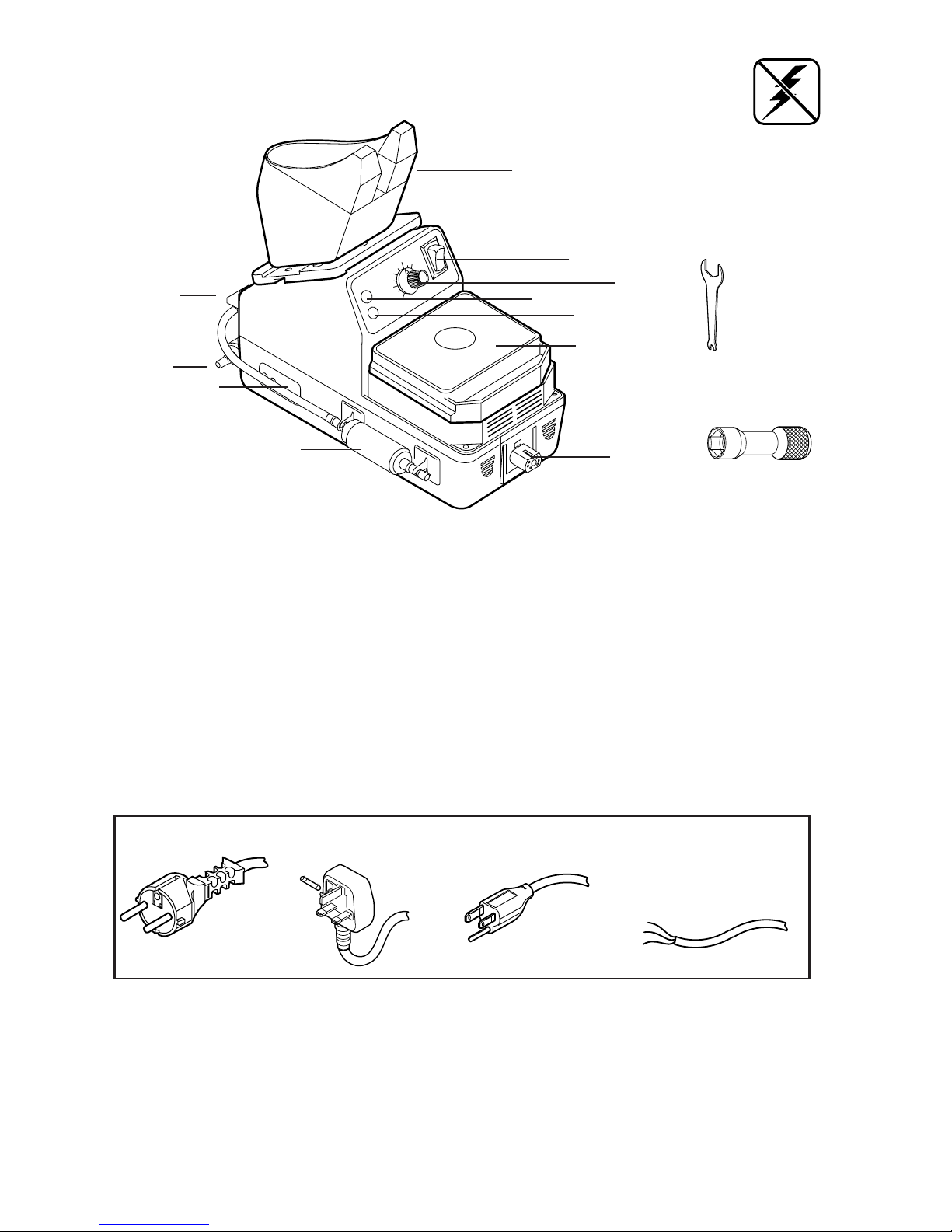
FEATURES
Static Safe
POWER SUPPLY
K
A) Tool Pod, equipped with micro-switch to activate pump.
B) Power Switch, to activate WorkStation.
C) Temp. Control Knob
D) Pump LED
E) Heater LED
F) SH232 Sponge Holder, with cleaning sponge.
G) Power output, 24V, controlled
H) AF110 Filter, (note ow direction)
I) External Calibration
J) Pump
K) WT623 Tip Wrench
L) WT619 Tip Wrench
A
B
C
E
F
D
G
J
H
I
H
L
SPECIFICATIONS
• 230V, 50/60 Hz, 150W Power Supply
• 24V, 50/60 Hz, 70W Hand Tool
• Weight; Power Supply: 5 lbs. 12 ozs. (2.6 kg)
Hand Tool: 11 ozs. (312 g)
• Temperature range of 400°F to 800°F (205°C-425°C)
• Voltage leakage from tip to ground, less than 2 MV
• Tip to ground resistance, less than 2 ohms
• COMPLIES WITH MIL-S-45743E, DOD-STD-2000-1B, WS-6536E and
ESD SPEC, DOD-STD-1686, DOD-HDBK-263
Page 3
DISTINGUISHING FEATURES
For ZD500DX-230 For ZD500DX-230P
POWER CORD WIRING
BROWN to LINE
BLUE to NEUTRAL
GRN/YEL to GROUND
For ZD500DX-230B
3A Fuse inside
For ZD500DX-230I
Not CE Approved
Power Cord

A) Head Assembly- Includes the primary
ltering system and solder debri chamber.
B) Hot Tip Desoldering Tip- Wide range of
desoldering Tips applicable.
C) Head Shaft- Allows 4-point rotation of
Head Assembly.
D) Trigger- Activates vacuum suction.
E) Vacuum Hose- Low Static silicone hose.
Connects to vacuum source.
F) Connector- To 24 V controlled output.
(for HT500) (for HT500-2)
G) Cleaning Shaft- For cleaning Desoldering
Tip orice: .05 (1.3 mm) and .025 (0.6
mm)
HT500/-1/-2
®
Hot Tip Desoldering Tool
D
A
F (for HT500-1)
E
B
C
ESD Safe
FEATURES
HOT TIP DESOLDERING TOOL
1. Insert nut into the slot of adapter plate on both sides.
2. Screw PA233 on the adapter plate.
PA233 Dovetail Extension Bracket allows
you to install additional Tool Pods.
OPTIONS
FC641 Large Filter Cartridge Assembly
Replaces FC640. For use in applications
that require heavy use, or where No-Clean
solder/ux is used at high temperature.
Page 4
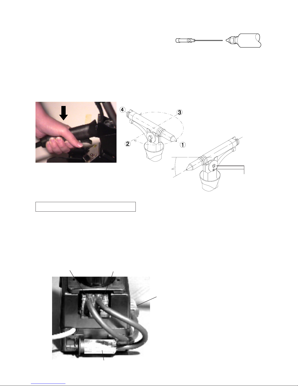
ADJUSTMENTS
The HT500 Head assembly can be adjusted into varying positions to suit the operator.
While Tool is in the Pod, push handle
down and twist handle until it locks
into 1 of it's 4 positions. Twisting
counter-clockwise will permit a 1800
turn. Twisting clockwise will permit
a 900 turn.
Note: Head Assembly does not make a full 3600 turn
To tilt the Head assembly, loosen (2)
Adjustment Screws. Tilt the Head assembly to de s ired positio n. Ret i ghten
Screws.
adjustment
screws
Air out
Vacuum
Air out
Vacuum
AIR FLOW DIRECTION
Hoses must be clean and not
kinked or cracked
For Factory repair:
Specify the problem and ship the
unit to EDSYN INC.
Customer Service
15958 Arminta Street
Van Nuys, CA 91406-1896
NOTE: When Tip orice is blocked,
use a correct size Cleaning Shaft
while pressing the Trigger to clear the
obstruction.
CS468 is .05 in. dia.
CS468-1 is .025 in. dia.
OPERATION
1. Connect HT500 to 24V power supply and vacuum source.
2. Press trigger to activate vacuum.
3. Always clean the Tip with wet sponge and
always re-tin (add fresh solder) during and after each
operation.
Page 5
 Loading...