

Page 1
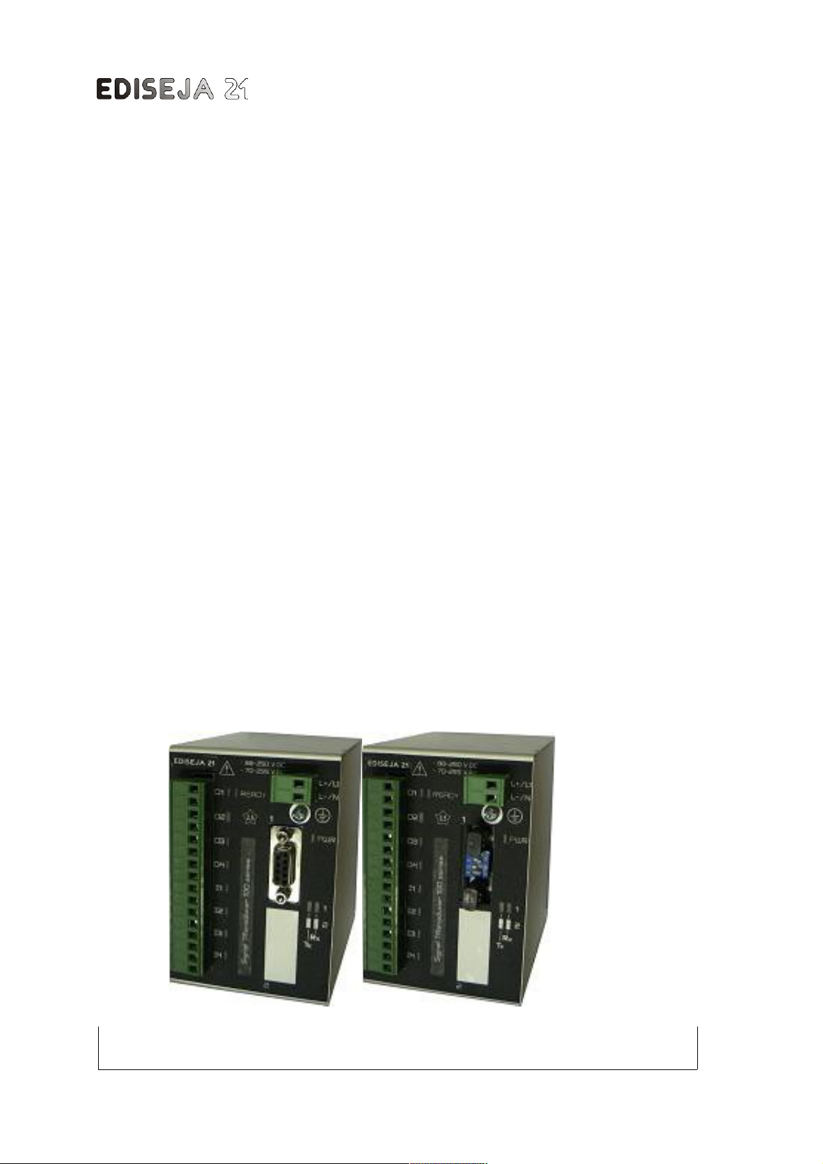
STR 100
Company: Device: Document: Code: Date:
Ediseja 21 STR 100 User manual STRMUED1 09.08.2019
STR 100
Signal Transducer
User manual
Page 2

STR 100 - Signal Transducer
Content
1 PREFACE.......................................................................................................4
2 STR 100 SYSTEM..........................................................................................6
2.1 DESCRIPTION..................................................................................................................... 6
2.2 FEATURES.......................................................................................................................... 6
2.3 FUNCTION........................................................................................................................... 6
2.4 TYPICAL APPLICATION..................................................................................................... 7
2.5 CONSTRUCTION................................................................................................................. 7
2.6 HOUSING............................................................................................................................. 8
2.7 INTENDED USE................................................................................................................... 8
3 DEVICE...........................................................................................................9
3.1 APPEARANCE..................................................................................................................... 9
4 HARDWARE DESCRIPTION.......................................................................10
4.1 MAIN BOARD..................................................................................................................... 10
4.2 INTERFACE BOARDS....................................................................................................... 10
4.2.1 RS232 INTERFACE BOARD........................................................................................... 10
4.2.2 RS485 INTERFACE BOARD........................................................................................... 11
4.2.3 VERSATILE LINK FIBER OPTIC INTERFACE BOARD..................................................13
4.2.4 MULTIMODE FIBER OPTIC INTERFACE BOARD......................................................... 14
4.2.5 SINGLEMODE FIBER OPTIC INTERFACE BOARD.......................................................14
4.2.6 10/100BASE-TX ETHERNET INTERFACE BOARD.......................................................15
4.2.6.1 LANTRONIX INSTALLER SETTINGS..........................................................................16
4.3 IO BOARDS....................................................................................................................... 21
5 SCHEMATIC.................................................................................................26
5.1 STR 100 / x.x.NON.IOx......................................................................................................26
5.2 STR 100 / x.x.NON.IOxR................................................................................................... 27
6 TYPICAL CONNECTION.............................................................................28
7 INSTALLATION............................................................................................29
7.1 INSTALLATION.................................................................................................................. 29
7.2 DEVICE SETTING.............................................................................................................. 30
Page: Company: Device: Document: Code: Date:
2 Ediseja 21 STR 100 User manual STRMUED1 09.08.2019
Page 3

8 COMMISSIONING & MAINTENACE..........................................................31
8.1 COMMISSIONING.............................................................................................................. 31
8.2 MAINTENANCE................................................................................................................. 31
9 TECHNICAL DATA......................................................................................32
10 DIMENSIONS.............................................................................................37
11 ORDERING.................................................................................................38
Company: Device: Document: Code: Date: Page:
Ediseja 21 STR 100 User manual STRMUED1 09.08.2019 3
Page 4
STR 100 - Signal Transducer
1 PREFACE
Liability statement
We have checked the contents of this manual to ensure that the descriptions of both hardware
and software are as accurate as possible. However, deviations may occur so that no liability can
be accepted for any errors or omissions contained in the information given.
The contents of this manual will be checked in periodical intervals, corrections will be made in
the following editions.
We reserve the right to make technical improvements without notice.
Contact
If you have any questions or comments related to this product please contact us on:
Ediseja 21 d.o.o.
Drenov Gric 175
1360 Vrhnika
Slovenia – EU
Tel: 00 386 51 643 411, 051 643 411
Email: [email protected]
www.ediseja21.com
Copyright
Copyright © Ediseja 21, 2013. All rights reserved.
Explanation of the symbols
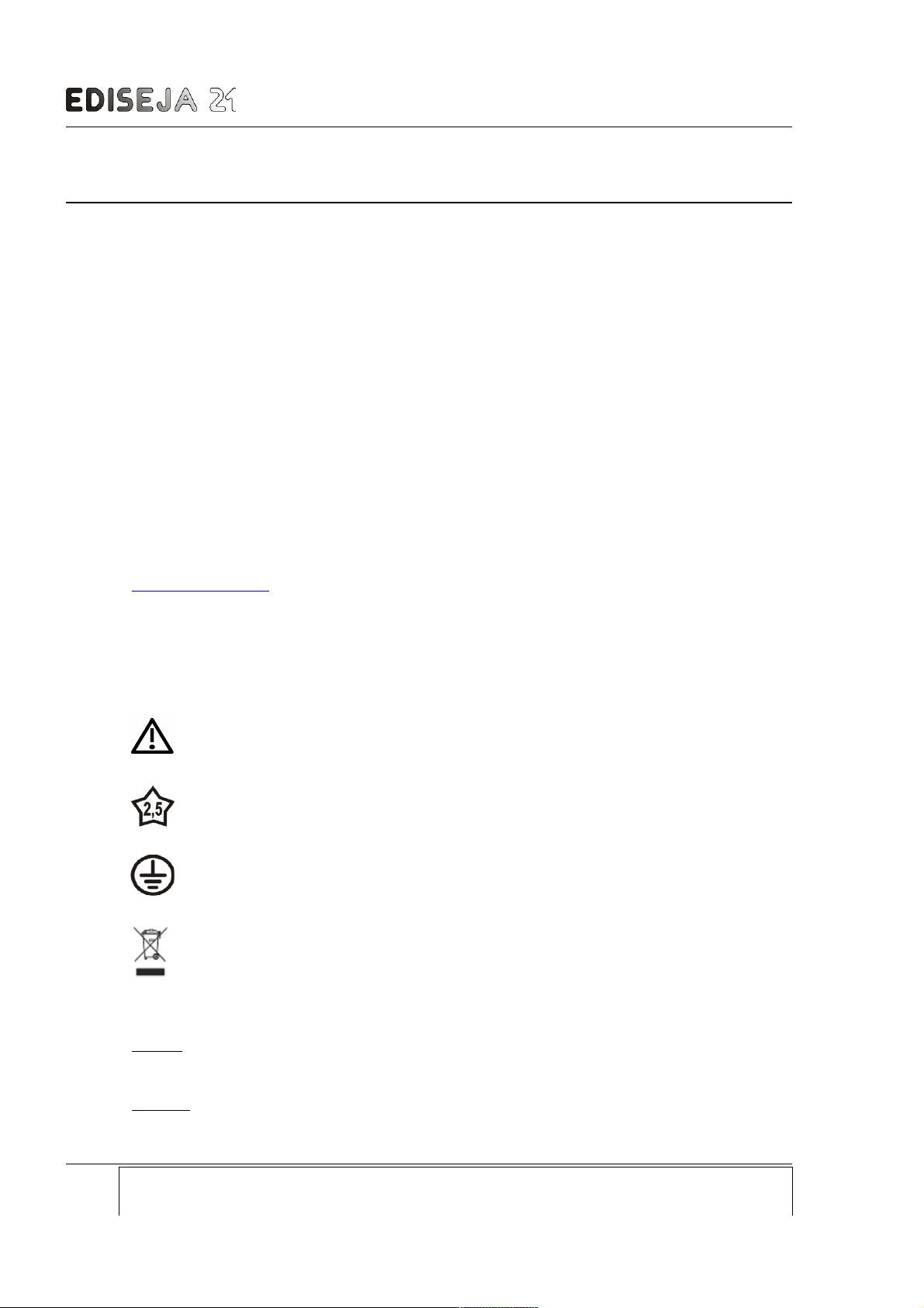
Read the instructions!
Device was tested with 2,5 kV AC voltage to check the device insulation.
Device ground terminal.
Waste Electrical and Electronic Equipment (WEEE) Directive 2002/96/EC; the affixed
product label indicates that you must not discard this electrical/electronic product in
domestic household waste.
Warnings
In this paper the following terms are used:
Danger
indicates that death, severe personal injury or substantial property damage will result if proper
precautions are not taken.
Warning
Page: Company: Device: Document: Code: Date:
4 Ediseja 21 STR 100 User manual STRMUED1 09.08.2019
Page 5
PREFACE
indicates that death, severe personal injury or substantial property damage can result if proper
precautions are not taken.
Caution
indicates that minor personal injury or property damage can result if proper precautions are not
taken. This particularly applies to damage on or in the device itself.
General information
These paper contain the information that is necessary for the proper and safe operation of the
described devices. This paper is intended for technically qualified personnel.
Warning!
Hazardous voltage is present inside the device during operation. Disregarding of safety
rules can result in severe personal injury or property damage.
Only qualified personnel may work with described devices after being familiar with warnings and
safety notices in this paper and other safety regulations.
Warning!
Device must operate completely assembled! Device must be used as described. No
modifications of the device should be made.
Warning!
Do not open device while it is energized! Hazardous voltage is present inside the
device. Disconnect all connectors before opening!
Warning!
If device is damaged disconnect it from power supply! Send it to the manufacturer for
inspection.
Warning!
Connect to earth before attaching power supply!
Company: Device: Document: Code: Date: Page:
Ediseja 21 STR 100 User manual STRMUED1 09.08.2019 5
Page 6
STR 100 - Signal Transducer
2 STR 100 SYSTEM
2.1 DESCRIPTION
STR 100 is modular system of communication devices that can be used for various of tasks
such as:
distance protection criteria transfer
disconnector and circuit breaker statuses transfer between substations
signal transfer via communication through noisy industrial enviroment
status and command transfer for remote switch
2.2 FEATURES
Wide range power supply
Digital input voltage suitable for substation's power supply
RS232, RS485, Fiber Optic or Ethernet communication interface
Switch selected BAUD rate
4 digital inputs
4 dIgital outputs
DIN 35 rail mount
Short response time
2.3 FUNCTION
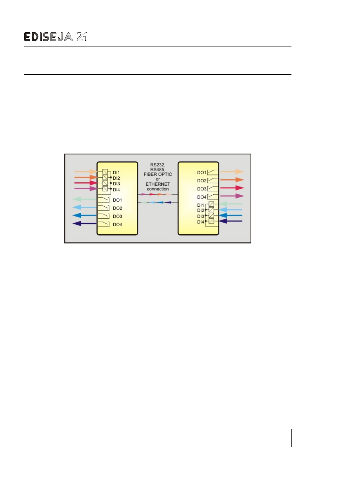
Two devices from STR 100 system works in pair. Input statuses from one device are transfered
to second device outputs and vice versa.
Devices are coupled through full duplex commnication link. Communication is based on special
protocol. If communication link is broken DO statuses of both devices are returned to theirs inital
states. Speed of communication can be selected by switches.
One of DOs has two functions. It can operate as normal DO or as communication failed
signalization. Selection between functions is made by switch.
Page: Company: Device: Document: Code: Date:
6 Ediseja 21 STR 100 User manual STRMUED1 09.08.2019
Picture 1: STR 100 block schematic
Page 7
FUNCTION
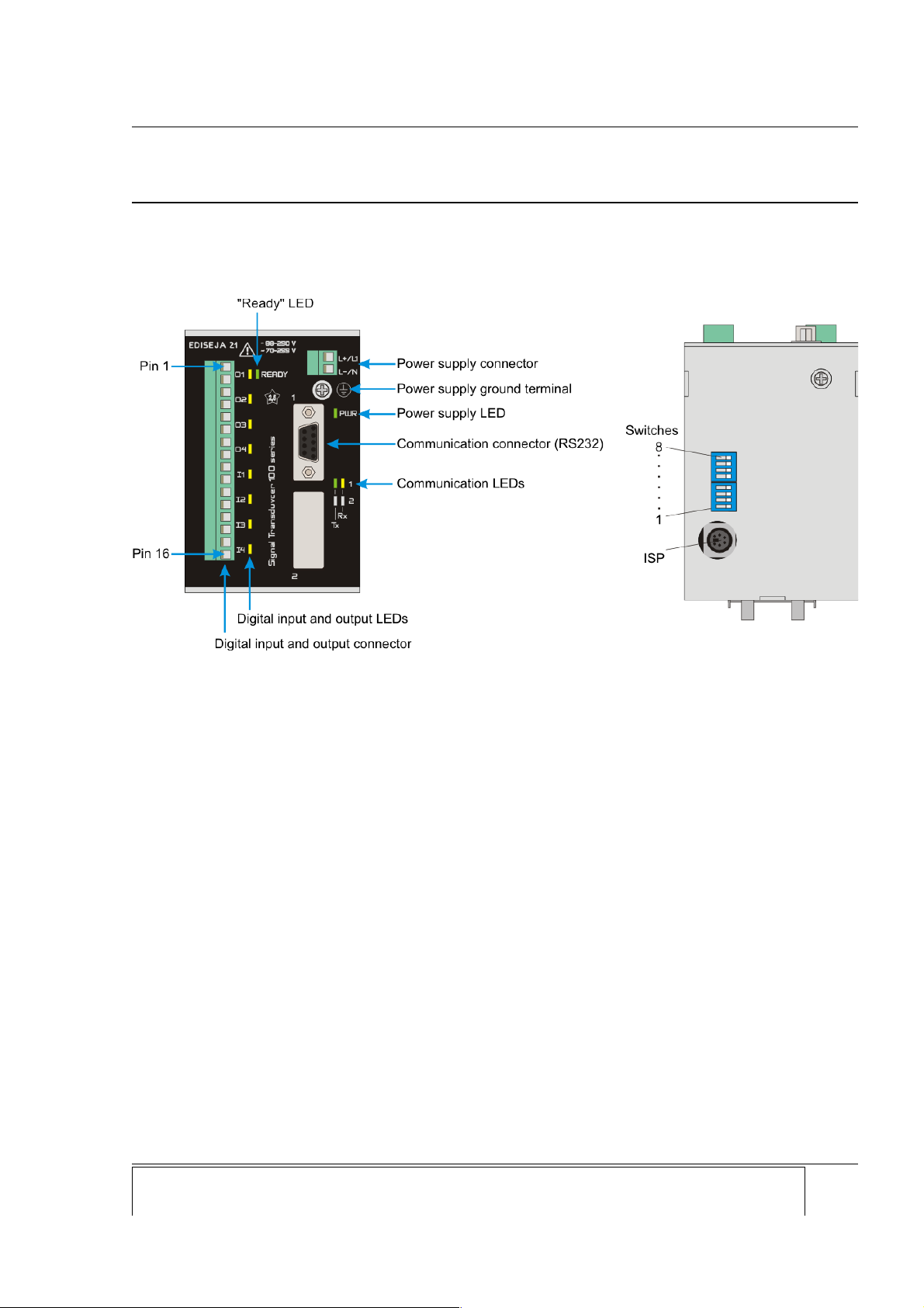
All normaly used connectors, switches and light indicators are accessed at the front side of the
device. One light indicator indicates power supply voltage, others indicate communication and
IOs activity.
2.4 TYPICAL APPLICATION
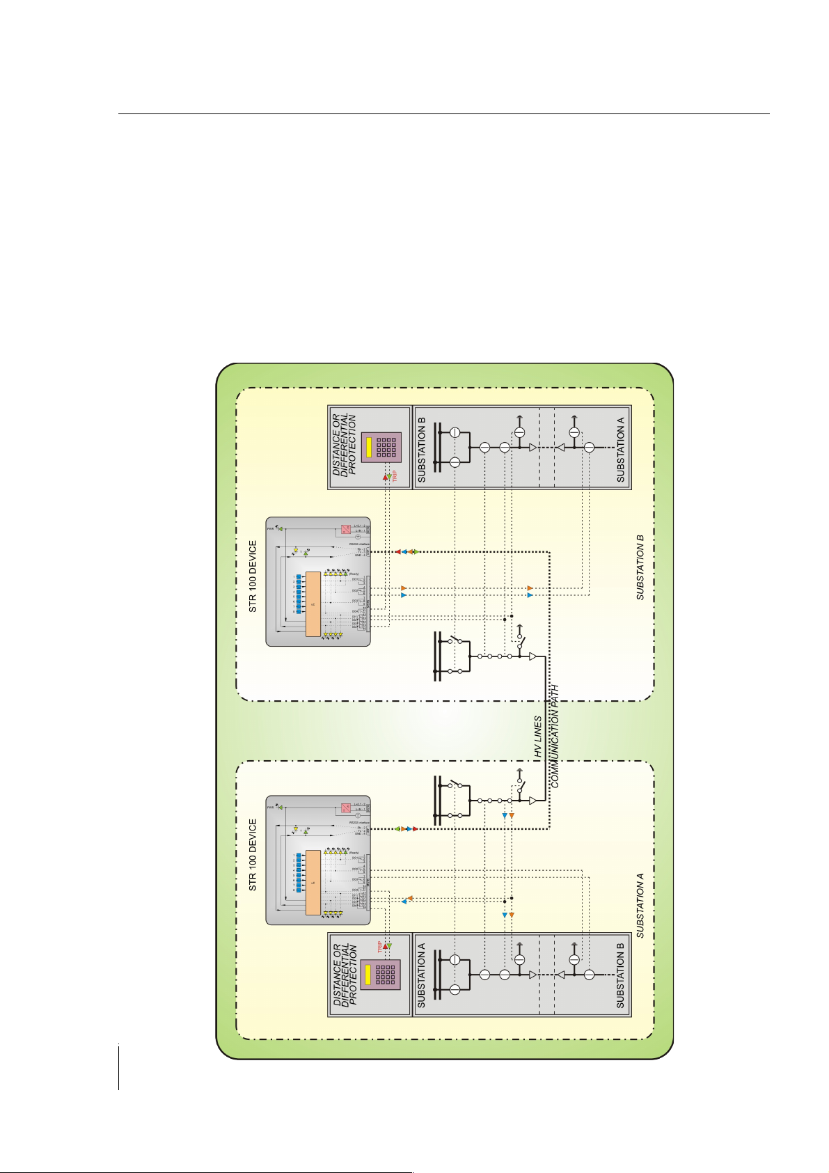
Typical application is transfer of trip command and circuit breaker status between two
substations.
2.5 CONSTRUCTION
Company: Device: Document: Code: Date: Page:
Ediseja 21 STR 100 User manual STRMUED1 09.08.2019 7
Picture 2: STR 100 typical application
Page 8

STR 100 - Signal Transducer
All devices from STR 100 system are based on various boards. There are three groups of
boards. One main board, one or two communication boards and one IO board is used in one
device :
main board with power supply
HI – high voltage power supply board
MD – medium voltage power supply board
LO – low voltage power supply board
communication interface
RS232 board
RS485 board
Versatile (650 nm) 1 mm plastic fiber optic board (~110 m)
Multimode (820 nm) fiber optic board (~2000 m)
Singlemode (1310 nm) fiber optic board (~20 km)
Ethernet board
IO board
IOL – 4 Digital Input (24 V DC), 4 Digital Output board
IO4 – 4 Digital Input (48 V DC), 4 Digital Output board
IO1 – 4 Digital Input (110 V DC), 4 Digital Output board
IO2 – 4 Digital Input (220 V DC), 4 Digital Output board
User can order any combination that suits him or her best.
2.6 HOUSING
Housing of STR 100 system devices is aluminium and intended for mount on standard DIN 35
rail (acc. to DIN EN 50022-35). Housing is same for all combinations.
2.7 INTENDED USE
Device are intended for use in cubicles and cabinets in all kinds of power production,
transmission and distribution stations as well as in industry. It requires no maintenace.
Page: Company: Device: Document: Code: Date:
8 Ediseja 21 STR 100 User manual STRMUED1 09.08.2019
Page 9
DEVICE
3 DEVICE
3.1 APPEARANCE
Other types of device are same except communication interface connectors are different.
Company: Device: Document: Code: Date: Page:
Ediseja 21 STR 100 User manual STRMUED1 09.08.2019 9
Picture 3: STR 100 / x.232.NON.x front view (left), bottom view (right)
Page 10
STR 100 - Signal Transducer
4 HARDWARE DESCRIPTION
Hardware is based on main board (power supply), interface board and IO board (DIs and DOs).
4.1 MAIN BOARD
Main board provides neccesary power to other parts of the device and place for interface board.
On the board there are also three LEDs. The yellow LED shows activity on receive (Rx) line and
the green one shows activity on transmit (Tx) line. Additional green LED indicates the device
power supply activity.
User can choose between two main boards:
HI – high voltage power supply board
MD – medium voltage power supply board
LO – low voltage power supply board
Connector pin table
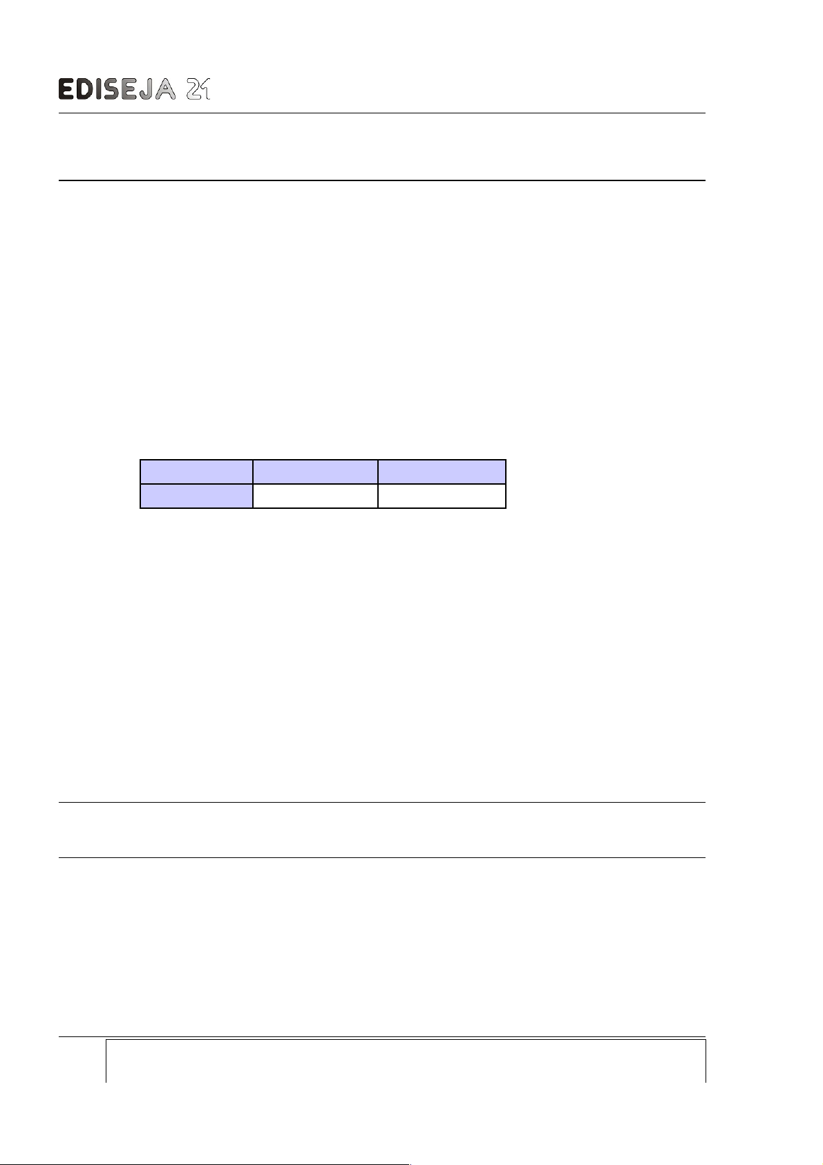
Phoenix MSTB 1 2
Description
L- , N L+, L1
For further technical data see chapter „TECHNICAL DATA“.
4.2 INTERFACE BOARDS
User can choose between following interface boards:
RS232 board
RS485 board
Versatile link plastic fiber optic board
Multimode Fiber Optic (ST connector) board
Singlemode Fiber Optic (SC connector) board
Singlemode Fiber Optic (FC connector) board
Singlemode Fiber Optic (ST connector) board
Ethernet board
Although STR 100 device can have two interfaces it can communicate only with one at the time.
Data is always received and transmited to both interfaces (ports).
4.2.1 RS232 INTERFACE BOARD
Description
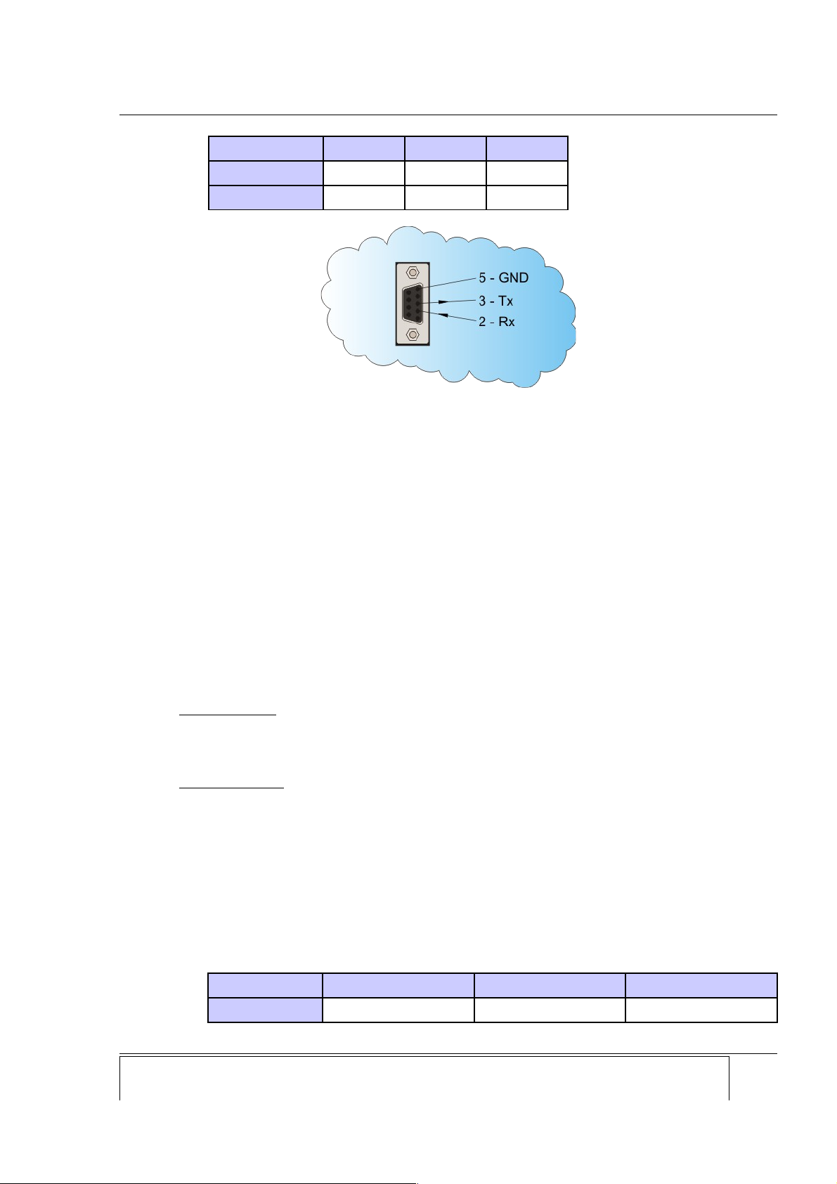
Single, nonisolated, full duplex, RS232 port with DB9 female connector. Supported Rx, Tx and
GND pins.
Connector pin table
Page: Company: Device: Document: Code: Date:
10 Ediseja 21 STR 100 User manual STRMUED1 09.08.2019
Page 11
INTERFACE BOARDS
DB9 F 2 3 5
Description
RX TX GND
Direction
IN OUT -
4.2.2 RS485 INTERFACE BOARD
Description
Single, galvanically isolated, half duplex, RS485 port with Phoenix 3 pin screw connector, with
automatic switch to receive after end of transmission and with additional terminating and
stabilizating resistors.
Hardware settings
For proper functioning of that board some settings must be done:
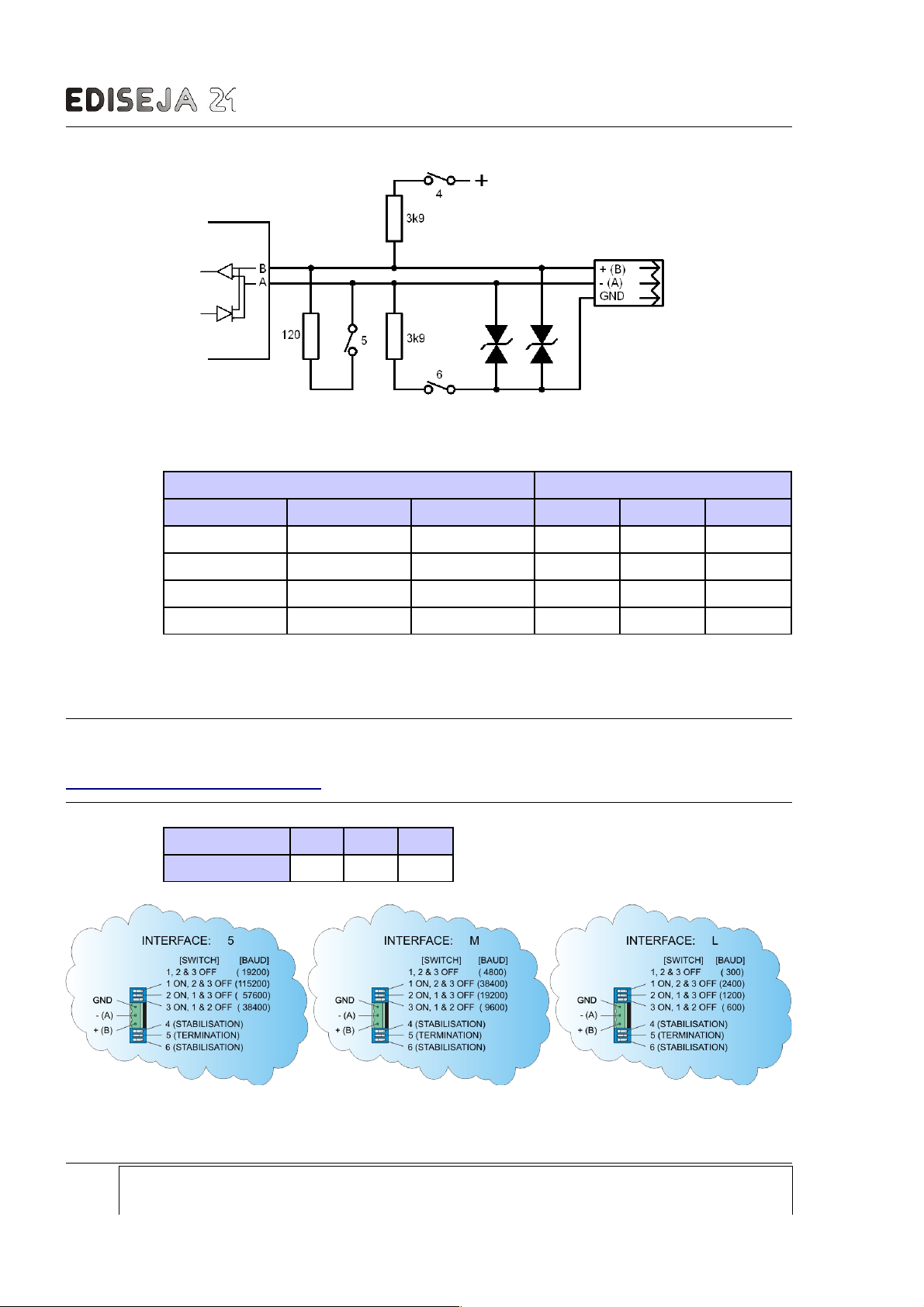
RS485 bus termination and stabilisation
baud rate
RS485 bus termination and stabilisation
TERMINATION
At high transmission rates or long distance, RS485 bus termination is necessary.
The termination on RS485 bus must be set on both ends of the RS485 bus.
STABILISATION
Some device, to work properly, demands that RS485 must always be in known and valid state.
That is, when + (positive) pin is more than 200 mV positive than – (negative) pin. Pins + and –
are sometimes marked as A and B. In case that no device on RS485 bus is transmitting or in
case of short circuit, there is no voltage difference between those pins and some device do not
work correctly.
On this port board so called „true fail-safe“ RS485 chip is used so board works correctly without
stabilisation at invalid RS485 bus state. But still switches for stabilisation are provided on port
board.
The stabilization on RS485 bus may be set on one device only!
Switches at the lower side of connector:
Switch 4 5 6
Description
RS485 stabilisation RS485 termination RS485 stabilisation
Company: Device: Document: Code: Date: Page:
Ediseja 21 STR 100 User manual STRMUED1 09.08.2019 11
Picture 4: DB9 Female connector
Page 12
STR 100 - Signal Transducer
Switches at the upper side of connector:
BAUD rate
BAUD rate Switch
Interface 5 Interface M Interface L 1 2 3
19200 4800 300
OFF OFF OFF
38400 9600 600
OFF OFF ON
57600 19200 1200
OFF ON OFF
115200 38400 2400
ON OFF OFF
BAUD rate setting 19k2 (bps) is valid for all standard communication protocols, that do not
request special timings. If special protocols (small request-respond time required) are used
please note it in order.
NOTE! If there are problems with communication, try using higher speed setting. Some
manufacturer have different markings for B and A line. Try to switch A and B wires. See
http://en.wikipedia.org/wiki/RS-485 for detailed information.
Connector pin table
MSTB 1 2 3
Description
GND - (A) + (B)
Page: Company: Device: Document: Code: Date:
12 Ediseja 21 STR 100 User manual STRMUED1 09.08.2019
Picture 5: RS485 BUS schematic
Picture 6: RS485 interface board appearance with switch settings
Page 13
INTERFACE BOARDS
4.2.3 VERSATILE LINK FIBER OPTIC INTERFACE BOARD
Description
Single receiver and transmitter, full duplex, 660 nm wave lenght, fiber optic port for 1 mm
diameter plastic fiber cable, up to 100 distance, with positive or negative logic, up to 40 kbit/s.
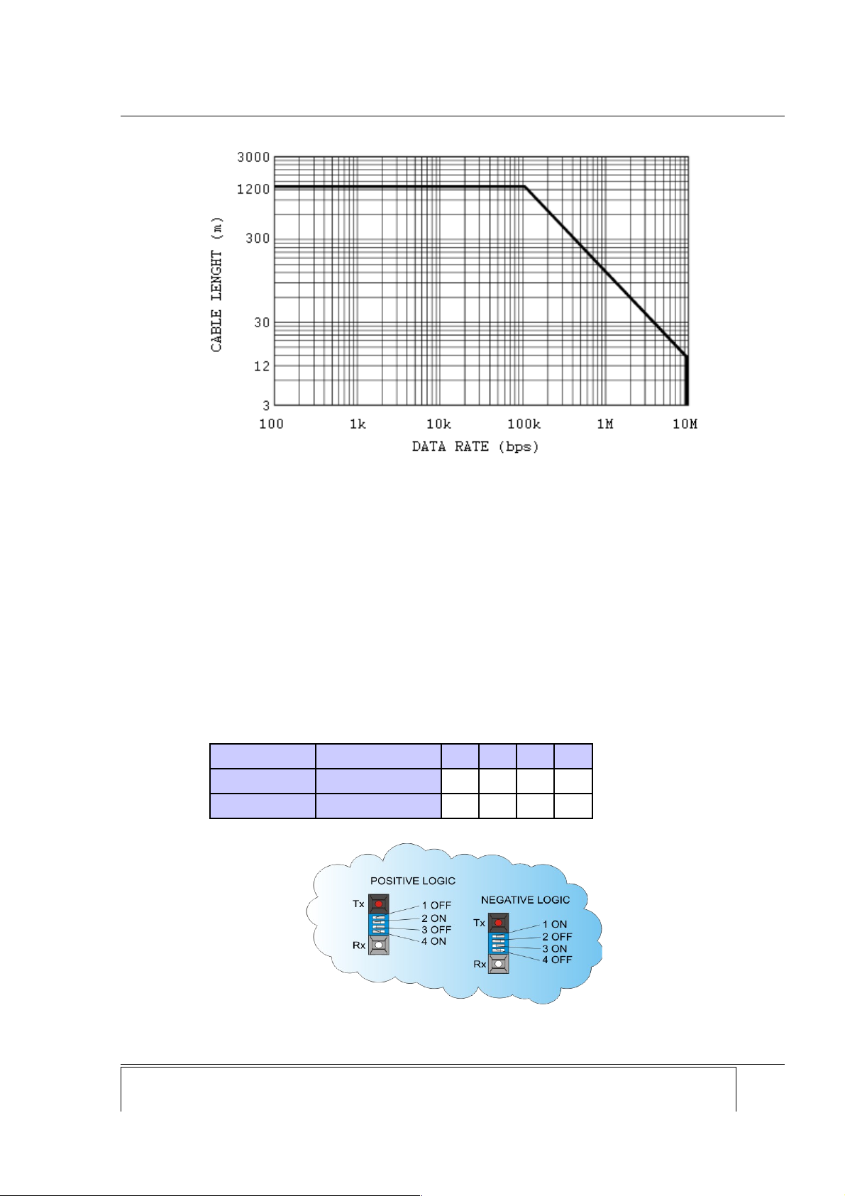
Hardware settings
For proper functioning of that port, optic logic must be set the same, on both devices that
communicates:
Fiber optic logic settings
Switch SW1 Light in idle state 1 2 3 4
Positive logic OFF
OFF ON OFF ON
Negative logic ON
ON OFF ON OFF
Company: Device: Document: Code: Date: Page:
Ediseja 21 STR 100 User manual STRMUED1 09.08.2019 13
Picture 7: Data rate vs cable lenght
Picture 8: Versatile link fiber optic interface board appearance
Page 14
STR 100 - Signal Transducer
4.2.4 MULTIMODE FIBER OPTIC INTERFACE BOARD
Description
Single, full duplex, multimode, fiber optic port with ST connectors with positive or negative logic.
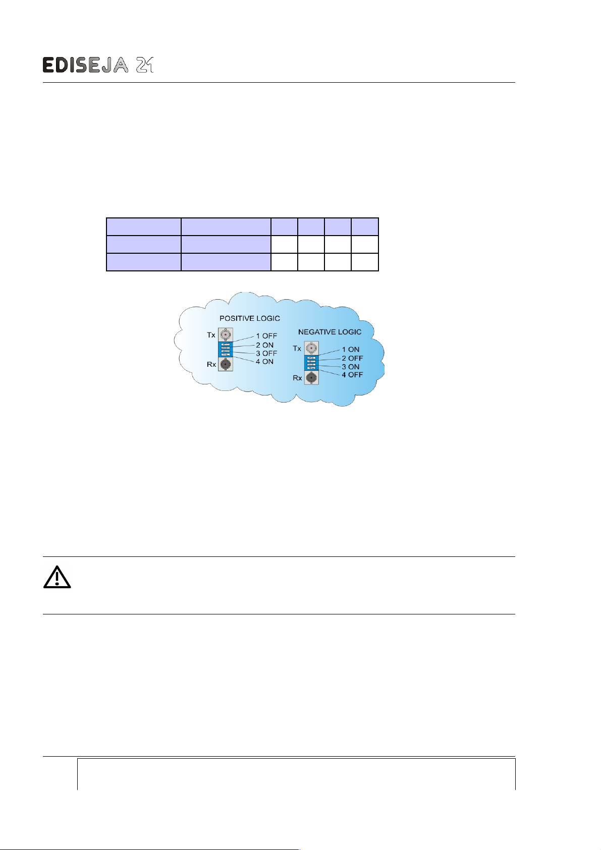
Hardware settings
For proper functioning of that board, optic logic must be set:
Fiber optic logic settings
Switch SW1 Light in idle state 1 2 3 4
Positive logic OFF
OFF ON OFF ON
Negative logic ON
ON OFF ON OFF
4.2.5 SINGLEMODE FIBER OPTIC INTERFACE BOARD
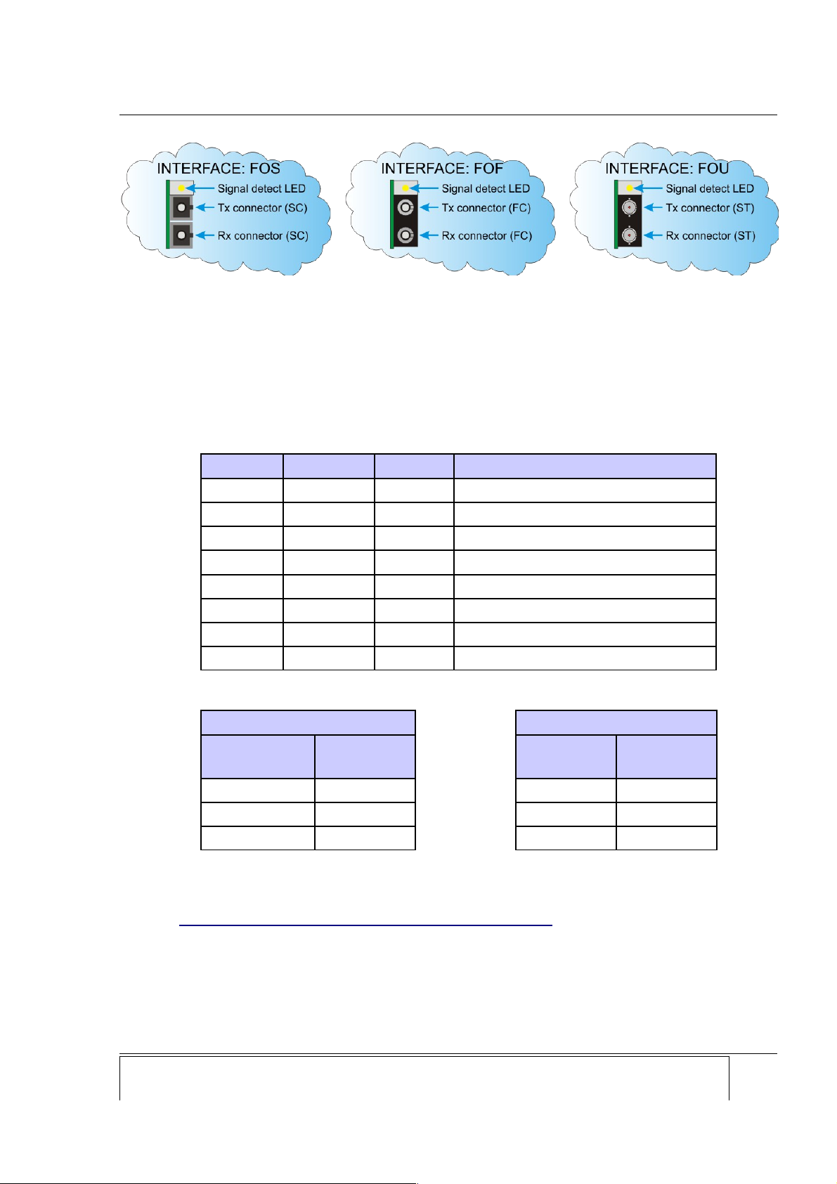
Description
Full duplex, singlemode, 1310 nm, up to 2,048 Mbit/s fiber optic port with SC connectors
(interface FOS), FC connectors (interface FOF) or ST connectors (interface FOU). This
interface allows transmission up to 20 km. Signal detect LED is activated, when receiver
receives enough light signal from transmitter from another end of the fiber cable.
Warning!
Radiation emitted by single mode laser devices can be dangerous to human eyes.
Avoid eye exposure to direct or indirect radiation.
Page: Company: Device: Document: Code: Date:
14 Ediseja 21 STR 100 User manual STRMUED1 09.08.2019
Picture 9: Multimode fiber optic interface board appearance
Page 15
INTERFACE BOARDS
4.2.6 10/100BASE-TX ETHERNET INTERFACE BOARD
Description
Ethernet port with RJ45 connector.
Interface signals
Signal Direction Contact Function
TX+ Out 1 Differential Ethernet transmit data +
TX- Out 2 Differential Ethernet transmit data -
RX+ In 3 Differential Ethernet receive data +
RX- In 4 Differential Ethernet receive data -
Not used 5 Terminated
Not used 6 Terminated
Not used 7 Terminated
Not used 8 Terminated
LED functions
Upper LED - Link Lower LED - Activity
Description Meaning
BAUD rate
selection
BAUD rate
selection
Off No Link Off No Activity
Amber 10 Mbps Amber Half Duplex
Green 100 Mbps Green Full Duplex
Software setting
For using this interface Installer program is needed. It can be obtained from
www.ediseja21.com\STR100-4channel-signal-transucer.htm. Installer program is needed for
setting IP, network mask,... Software can be obtained from www.lantronix.com.
Company: Device: Document: Code: Date: Page:
Ediseja 21 STR 100 User manual STRMUED1 09.08.2019 15
Picture 10: Singlemode fiber optic interface board appearance
Page 16
STR 100 - Signal Transducer
4.2.6.1 LANTRONIX INSTALLER SETTINGS
Page: Company: Device: Document: Code: Date:
16 Ediseja 21 STR 100 User manual STRMUED1 09.08.2019
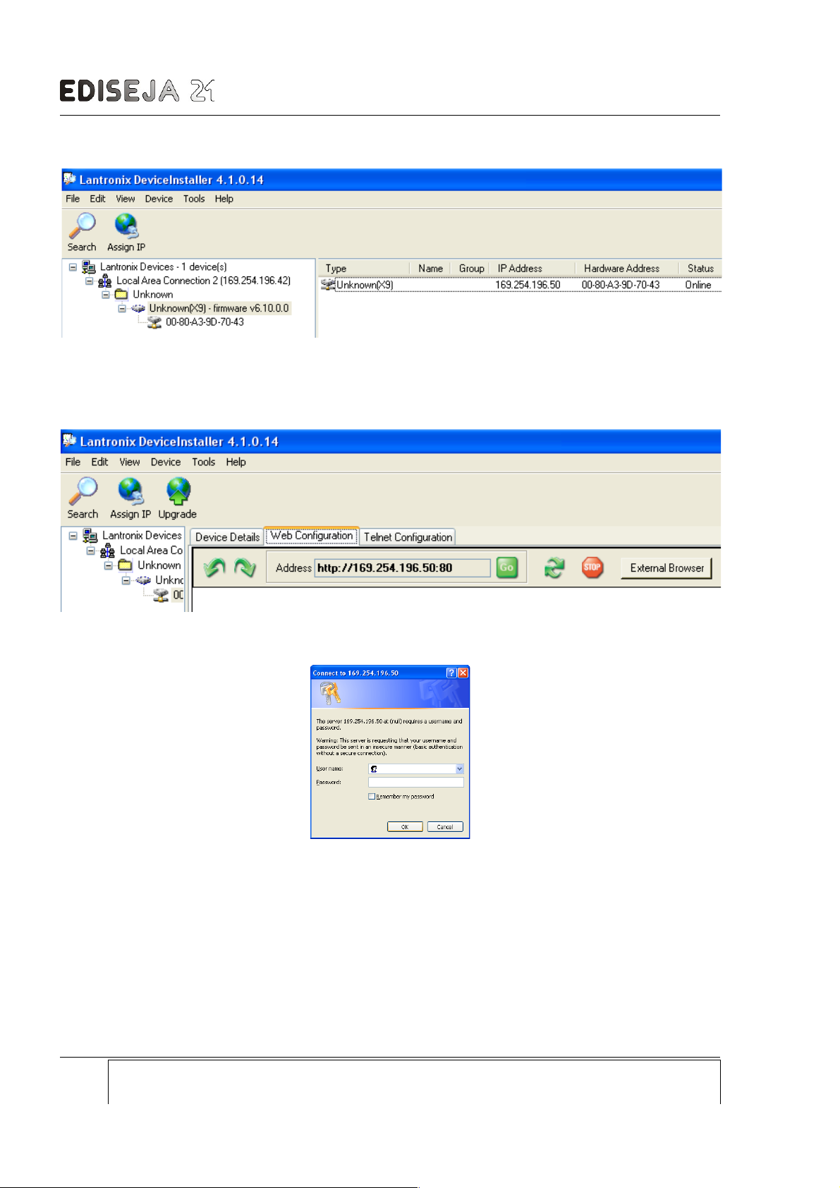
Picture 11: Start program and press "Search" to find device, then select device to be set, press icon
Assign IP, type request IP number and press button Assign
Picture 12: Press "Web Configuration"
Picture 13: Press "Ok"
Page 17
INTERFACE BOARDS
Company: Device: Document: Code: Date: Page:
Ediseja 21 STR 100 User manual STRMUED1 09.08.2019 17
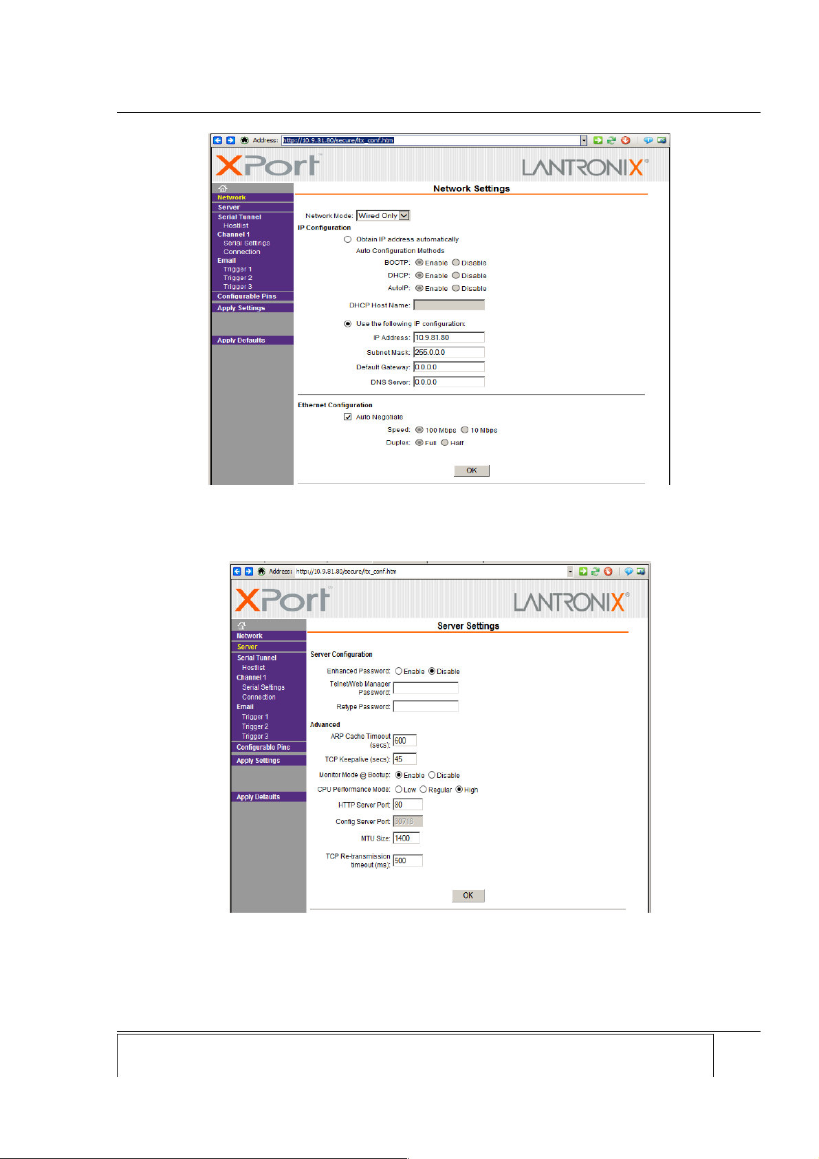
Picture 14: Use „IP Configuration/Use the following IP configuration:“ settings and set IP according to your
needs.
Picture 15: Set as shown on both STR devices
Page 18
STR 100 - Signal Transducer
Page: Company: Device: Document: Code: Date:
18 Ediseja 21 STR 100 User manual STRMUED1 09.08.2019
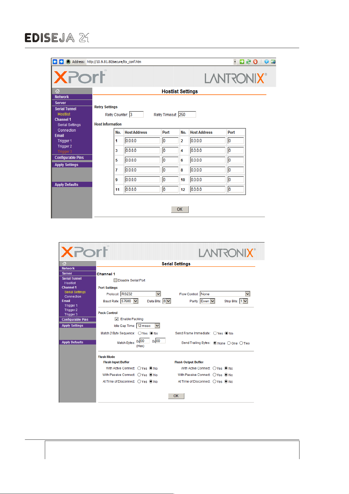
Picture 16: Hostlist settings on both STR devices
Picture 17: Serial Settings on both STR devices
Page 19

INTERFACE BOARDS
Setting Settings on both STR devices
Port Settings / Protocol RS232
Port Settings / Flow control None
Port Settings / Baud Rate 57600
Port Settings / Data Bits 8
Port Settings / Parity Even
Port Settings / Stop Bits 1
Pack Control / Enable Packing "checked"
Pack Control / Idle Gap Time 12 ms
NOTE! This are default factory settings. Do not change any of this settings, otherwise device can
stop working correctly!
Company: Device: Document: Code: Date: Page:
Ediseja 21 STR 100 User manual STRMUED1 09.08.2019 19
Page 20
STR 100 - Signal Transducer
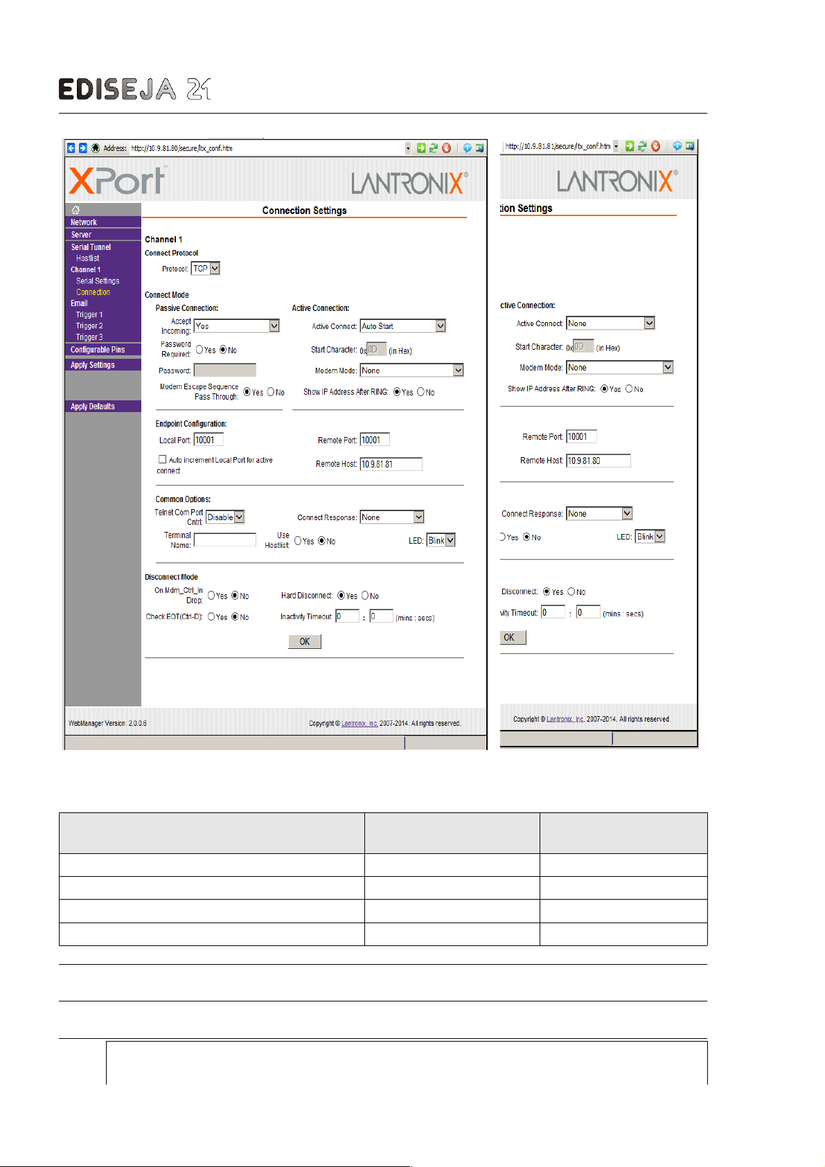
Setting Left picture - settings on
the first STR device
Right picture - settings on
the second STR device
Connect Mode / Active Connect "Auto Start" "None"
Endpoint Configuration / Local Port 10001 10001
Endpoint Configuration / Remote Port 10001 10001
Endpoint Configuration / Auto Increment Local.. "unchecked" "unchecked
NOTE! This are default factory settings. Do not change any of this settings, otherwise device can
Page: Company: Device: Document: Code: Date:
20 Ediseja 21 STR 100 User manual STRMUED1 09.08.2019
Picture 18: Connection Settings
Page 21

INTERFACE BOARDS
stop working correctly!
Setting Left picture - settings on
the first STR device
(exam. IP: 10.9.81.80)
Right picture - settings on
the second STR device
(exam. IP: 10.9.81.81)
Endpoint Configuration / Remote Host Second STR device IP
(IP: 10.9.81.81)
First STR device IP
(IP: 10.9.81.80)
Set IP on both STR devices according to your needs.
NOTE! Always press "OK" when settings is changed. Press „Apply Settings“ to save settings into
device! Wait for device to reset.
NOTE! If you want to check the setting on the device, close your web browser otherwise (old)
settings will be displayed from computer's cache rather than from STR device itself.
4.3 IO BOARDS
On boards are:
microcontroller
4 DIs
4 DOs or 3DOs + 1 „device ready“ DO (depends on ordering)
8 switches
Microcontroller is the heart of device. It scans DIs, controls DOs and communicates via protocol.
Digital inputs are scaned every 0,1 ms. Debounce filter is 20. That means that digital input will
be recognized as active, if in all 20 cycles status of digital input will be high.
Digital outputs 1-3 are controlled by communication. After positive command request, requested
digital output will be activated for 500 ms. After that time, digital output will be automaticly
returned to its initial state.
Digital inputs and digital outputs statuses are indicated by LEDs on front side of device.
User can choose from following list:
IOL – 4 Digital Input (24 V DC), 4 Digital Output board
IO4 – 4 Digital Input (48 V DC), 4 Digital Output board
IO1 – 4 Digital Input (110 V DC), 4 Digital Output board
IO2 – 4 Digital Input (220 V DC), 4 Digital Output board
IO4R – 4 Digital Input (48 V DC), 3 Digital Outputs + 1 „device ready“ DO board
IO1R – 4 Digital Input (110 V DC), 3 Digital Outputs + 1 „device ready“ DO board
IO2R – 4 Digital Input (220 V DC), 3 Digital Outputs + 1 „device ready“ DO board
Company: Device: Document: Code: Date: Page:
Ediseja 21 STR 100 User manual STRMUED1 09.08.2019 21
Page 22
STR 100 - Signal Transducer
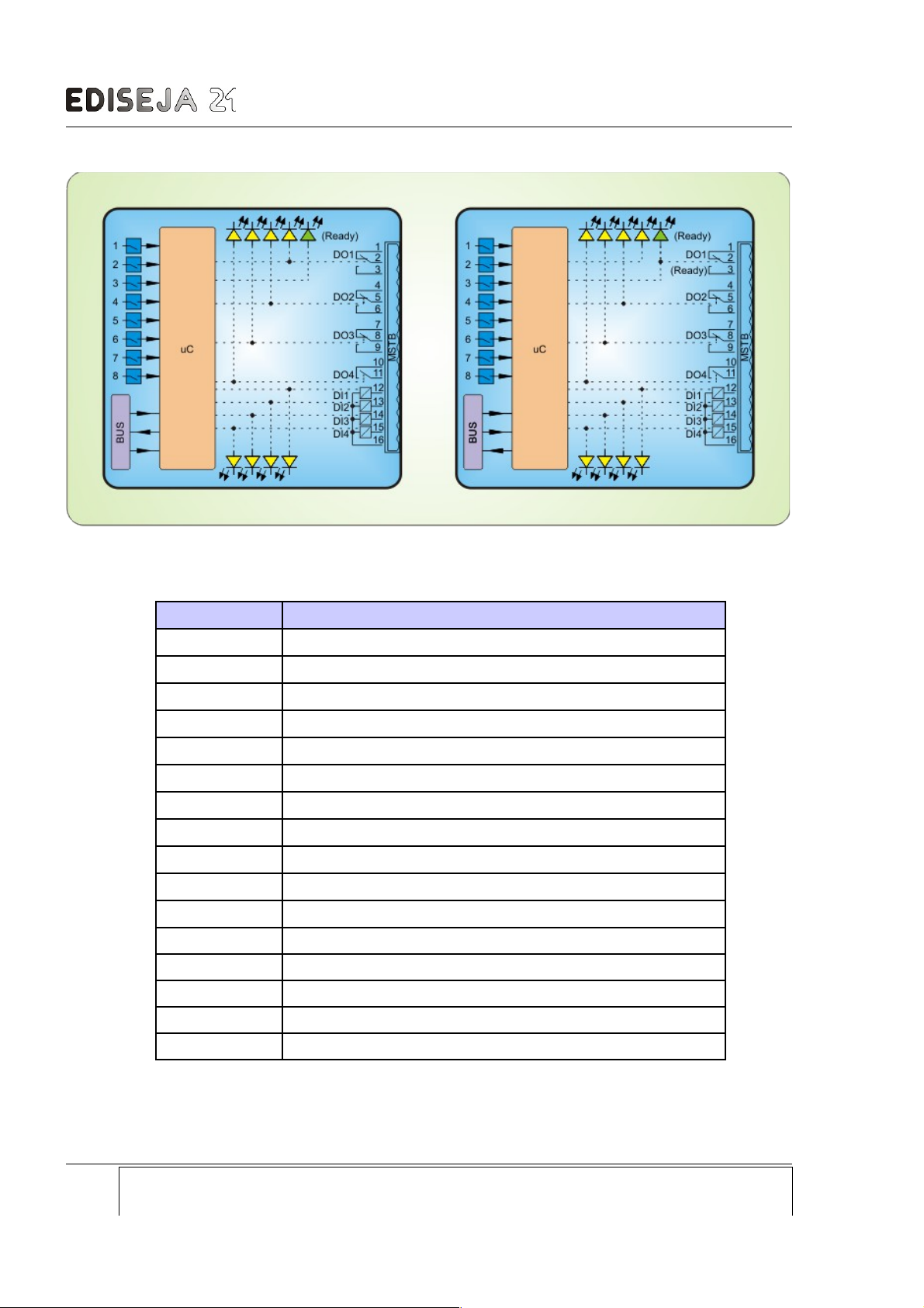
IO connector pin table (all IO board types)
Pin Description
1
potential free DO1 Normally Close contact pin
2
potential free DO1 Common pin
3
potential free DO1 Normally Open contact pin
4
potential free DO2 Normally Close contact pin
5
potential free DO2 Common pin
6
potential free DO2 Normally Open contact pin
7
potential free DO3 Normally Close contact pin
8
potential free DO3 Common pin
9
potential free DO3 Normally Open contact pin
10
potential free DO4 Normally Open contact pin
11
potential free DO4 Normally Open contact pin
12 DI1 input
13 DI2 input
14 DI3 input
15 DI4 input
16 DIs common GND
Difference between IOx and IOxR board is in operation of first DO (DO1).
Page: Company: Device: Document: Code: Date:
22 Ediseja 21 STR 100 User manual STRMUED1 09.08.2019
Picture 19: (left) IO1, IO2 & IO4 board schematic
Picture 20: (right) IO1R, IO2R & IO4R board schematic
(difference is in DO1 relay)
Page 23
IO BOARDS
Operation of DO1 on IOx boards
On IOx boards DO1 has two functions. They can operate as:
normal DO which is activated by activation of DI1 on other device
communication activity indicator. If communication is established DO1 is activated. If
communication is not established DO1 is in its initial position.
Function of DO1 is set by switch 5 at the bottom of device.
Operation of DO1 on IOxR boards
On IOxR boards DO1 has ready function. DO1 is energized when device is operating normally.
DO1 is deactivated when device has no power or device is not working correctly.
Operation of DO2 on IOx and IOxR boards
DO2 has two functions. It can operate as:
normal DO which is activated by activation of DI2 on other device
communication activity indicator. If communication is established DO2 is activated. If
communication is not established DO2 is in its initial position.
Function of DO2 is set by switch 6 at the bottom of device.
LEDs operation
LED ready signalize when device normaly operates. If power is on and green LED ready:
blinks or does not light; device does not operate correctly
lights; device operates normally
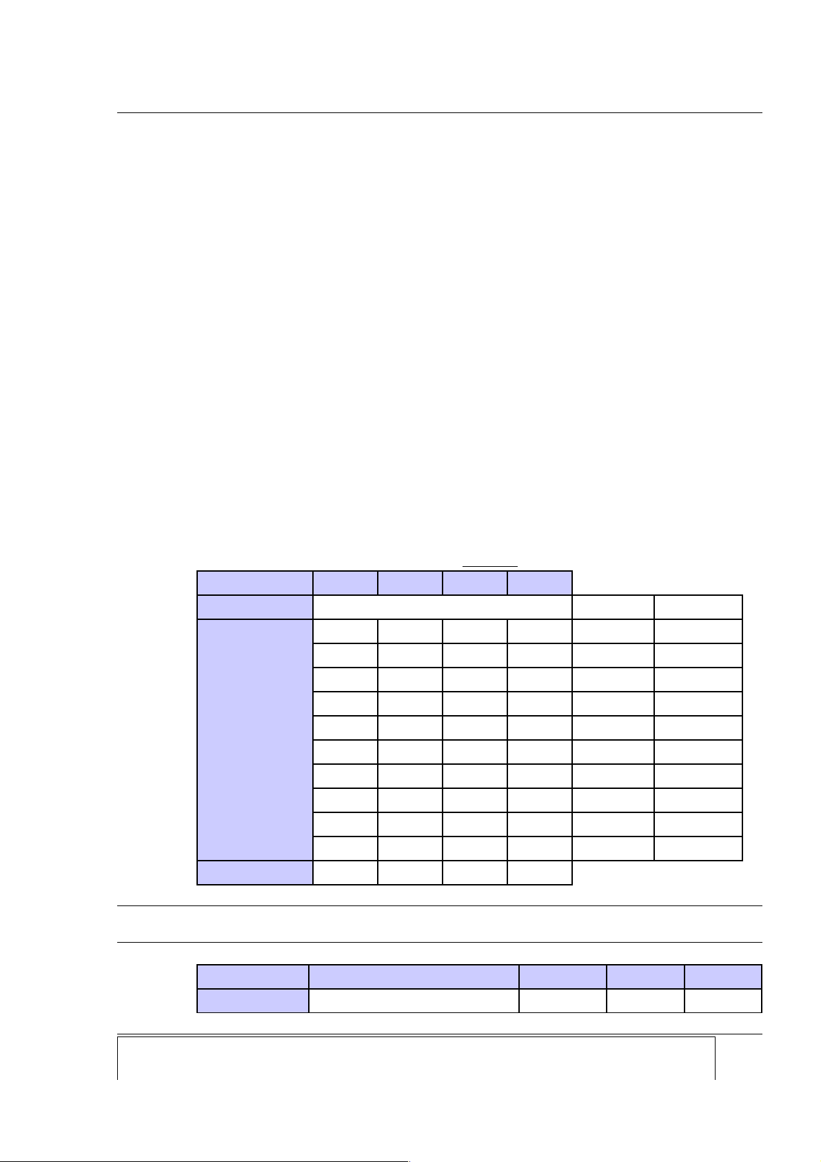
Switches at the bottom of the device - valid EXCEPT for STR 100 / x.ETH.x.x
Switch 1 2 3 4
Description
BAUD rate selection BAUD rate Trans. time
Position
OFF OFF OFF OFF
1200
110 ms
ON
OFF OFF OFF
2400
61 ms
OFF
ON
OFF OFF
4800
34 ms
ON ON
OFF OFF
9600
20 ms
OFF OFF
ON
OFF
14400
14 ms
ON
OFF
ON
OFF
19200
13 ms
OFF
ON ON
OFF
38400
10 ms
ON ON ON
OFF
57600
9 ms
OFF OFF OFF
ON 76800
8 ms
ON
OFF OFF
ON 115200
7 ms
Default position
ON OFF ON OFF
Note that setting of the BAUD rate must be same on both devices working in pair.
Switch 5 6 7 8
Description
DO1 DO2 function "master" / ethernet
Company: Device: Document: Code: Date: Page:
Ediseja 21 STR 100 User manual STRMUED1 09.08.2019 23
Page 24
STR 100 - Signal Transducer
Switch 5 6 7 8
function "slave" type
Position OFF
normal DO (IOx boards) or
„ready“ DO (IOxR boards)
normal DO
must be
used!
must be
used!
Position ON
communic. active (IOx boards)
or „ready“ DO (IOxR boards)
communic.
active
do not use! do not use!
Default position
ON OFF OFF OFF
If device is not ready, all DOs are deactivated!
It is recommended, that device setting is made before device is powered up.
Device settings set by this swithes are not regarded during operation, but only once after power
up! If change during operation is made, disconnect power supply for a few moments (until power
LED stops emitting) and connect power supply back. New settings are then accepted.
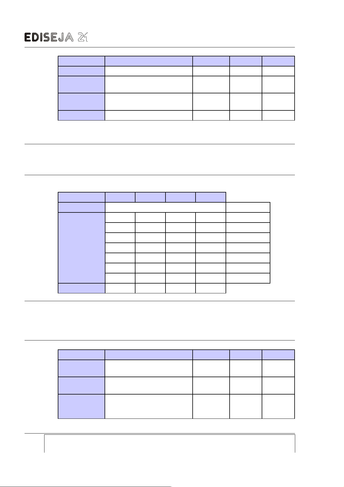
Switches at the bottom of the device - valid for STR 100 / x.ETH.x.x devices only
Switch 1 2 3 4
Description
communication fail delay delay (ms)
Position
OFF OFF OFF OFF
100
ON
OFF OFF OFF
200
OFF
ON
OFF OFF
400
ON ON
OFF OFF
800
OFF OFF
ON
OFF
1000
ON
OFF
ON
OFF
2000
OFF
ON ON
OFF
4000
Default position
ON ON OFF OFF
It is recommended that settings of time delay is the same on both devices working in pair.
Settings do not affect actual transmitting time. It only affects how long communication between
STR devices must be broken to each STR device drops output relays. Actual transmitting time
depends on network latency.
Switch 5 6 7 8
Description
DO1
function
DO2 function
"master" /
"slave"
ethernet
type
Position OFF
normal DO (IOx boards) or
„ready“ DO (IOxR boards)
normal DO
first STR
device
do not use!
Position ON
communic. active (IOx boards)
or „ready“ DO (IOxR boards)
communic.
active
second
STR
device
must be
used!
Page: Company: Device: Document: Code: Date:
24 Ediseja 21 STR 100 User manual STRMUED1 09.08.2019
Page 25

IO BOARDS
Switch 5 6 7 8
Default position
ON OFF OFF/ON ON
If device is not ready, all DOs are deactivated!
It is recommended, that device setting is made before device is powered up.
* Device settings set by this swithes are not regarded during operation, but only once after power
up! If change during operation is made, disconnect power supply for a few moments (until power
LED stops emitting) and connect power supply back. New settings are then accepted.
On the bottom side of device are switches for device setting and ISP connector which is
intended for upgradeing software. Do not connect anything to that connector.
For further technical data see chapter „TECHNICAL DATA“.
Company: Device: Document: Code: Date: Page:
Ediseja 21 STR 100 User manual STRMUED1 09.08.2019 25
Page 26
STR 100 - Signal Transducer
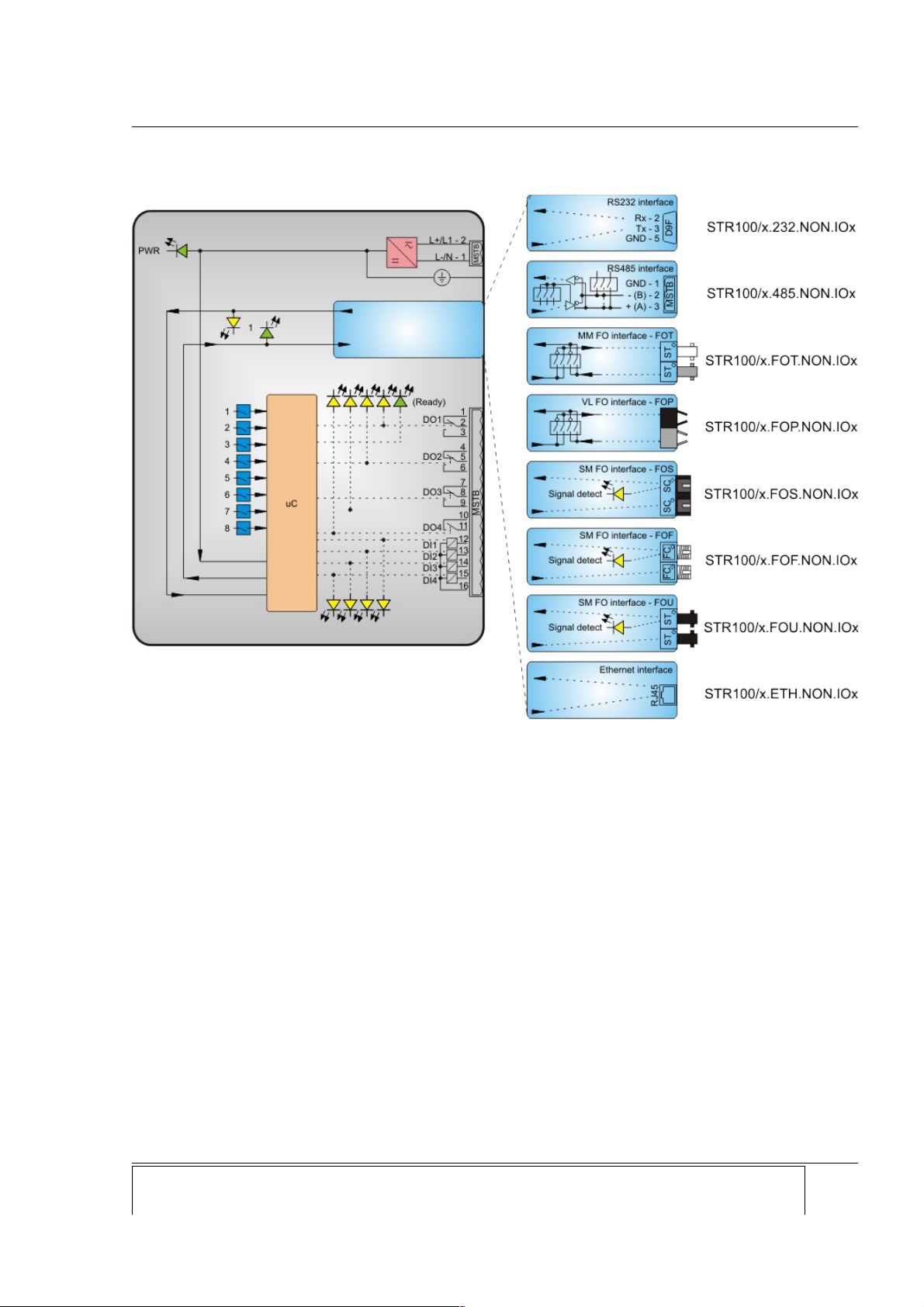
5 SCHEMATIC
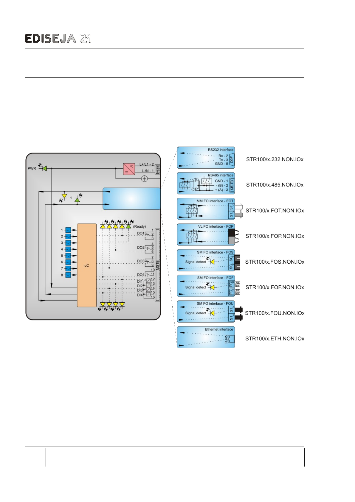
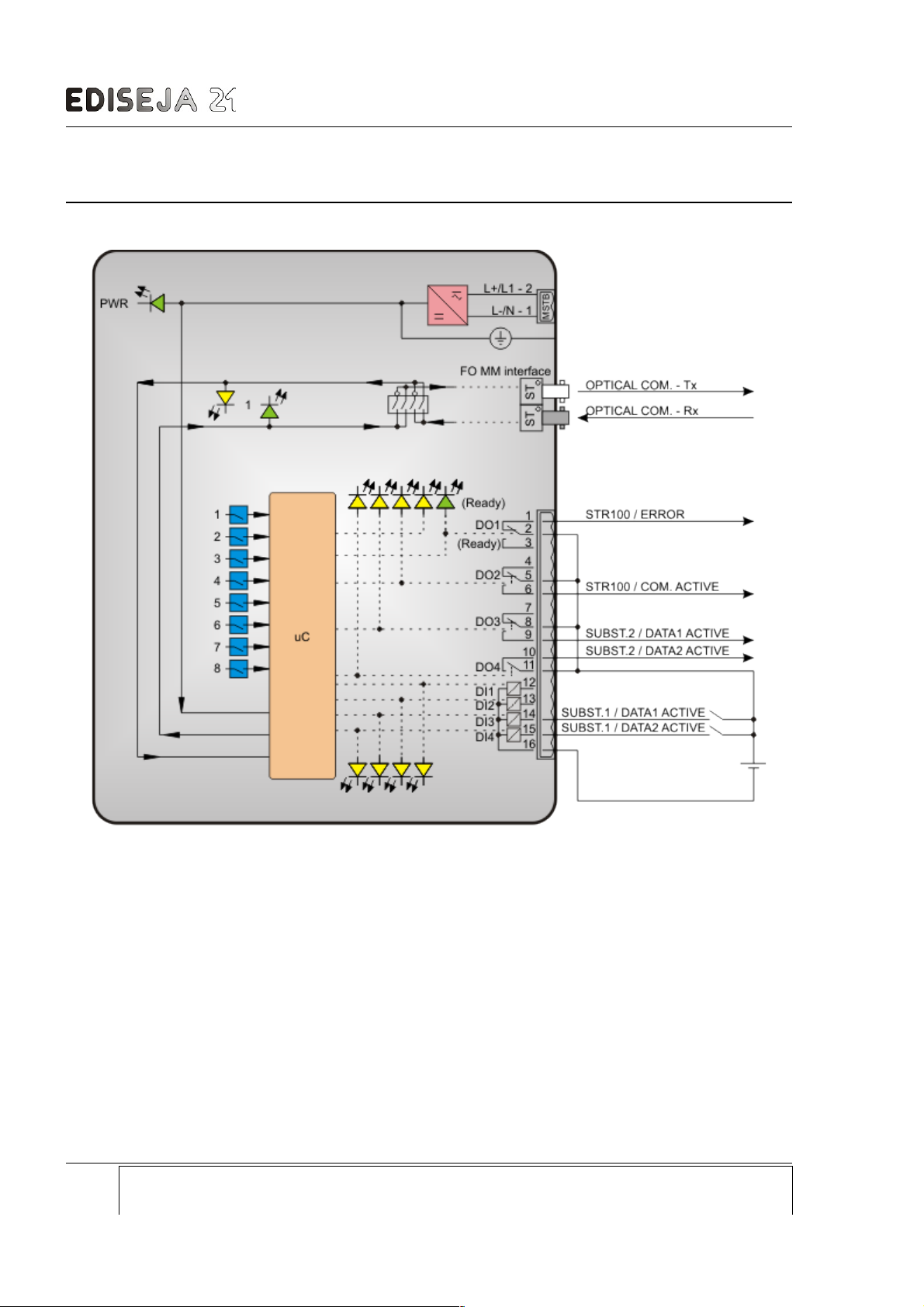
Difference between schematics is in operation of DO1. On first picture DO1 is normal digital output. On
second picture DO1 works as „ready“ indicator. For further details see chapter „HARDWARE
DESCRIPTION/IO BOARDS“.
5.1 STR 100 / x.x.NON.IOx
x - means any type, for types description see chapter Ordering.
Page: Company: Device: Document: Code: Date:
26 Ediseja 21 STR 100 User manual STRMUED1 09.08.2019
Picture 21: STR 100 / x.x.NON.IOx schematic
Page 27
STR 100 / x.x.NON.IOxR
5.2 STR 100 / x.x.NON.IOxR
Company: Device: Document: Code: Date: Page:
Ediseja 21 STR 100 User manual STRMUED1 09.08.2019 27
Picture 22: STR 100 / x.x.NON.IOxR schematic
Page 28
STR 100 - Signal Transducer
6 TYPICAL CONNECTION
Page: Company: Device: Document: Code: Date:
28 Ediseja 21 STR 100 User manual STRMUED1 09.08.2019
Picture 23: STR 100 / x.FOT.NON.IOxR typical connection
Page 29

INSTALLATION
7 INSTALLATION
7.1 INSTALLATION
Warning!
Hazardous voltage is present inside the device during operation. Disregarding of safety
rules can result in severe personal injury or property damage.
Only qualified personnel may work with described devices after being familiar with warnings and
safety notices in this paper and other safety regulations.
Following instruction must be taken into consideration:
The device must be accessible to qualified personnel only.
The device is permitted to operate in enclosed housing or cabinet only.
The device location must be vibration-free.
The admisible operating temperature must be observed.
Check the device for damage at unpacking. If device is damaged it must not be installed
but it should be send to the manufacturer for repair.
The device should not be opened.
The device should be mounted on a 35 mm rail (acc to EN 50022).
Attach ground wire before attaching power supply. Device must be grounded during
operation!
Single core or stranded wire 0,5 – 2,5 mm2 must be used for power supply connection. If
stranded wire is used, ferrules must be used to prevent fraying. Recommended stripping
lenght is 5 mm.
Protective earthing wire must be terminated with tinned copper ear terminal.
The prescribed bending radius of the optical fibre cables must be observed.
Company: Device: Document: Code: Date: Page:
Ediseja 21 STR 100 User manual STRMUED1 09.08.2019 29
Page 30
STR 100 - Signal Transducer
7.2 DEVICE SETTING
It is recommended, that device setting is made before device is powered up.
Some device settings are not regarded during operation, but only once after power up! If change
during operation is made, disconnect power supply for a few moments (until power LED stops
emitting) and connect power supply back. Settings are then accepted.
For further details see chapter „HARDWARE DESCRIPTION/“.
Page: Company: Device: Document: Code: Date:
30 Ediseja 21 STR 100 User manual STRMUED1 09.08.2019
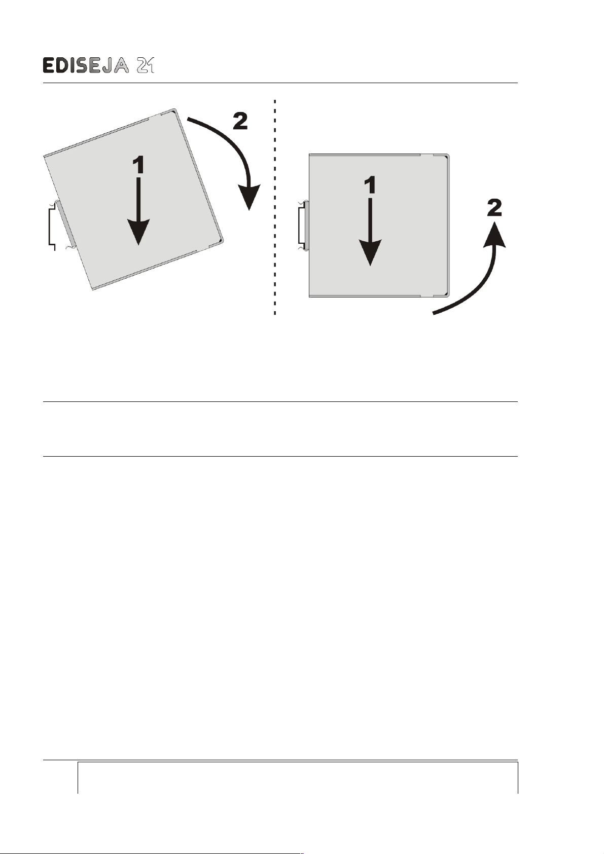
Picture 24: left. installation, right: deinstallation
Page 31
COMMISSIONING & MAINTENACE
8 COMMISSIONING & MAINTENACE
8.1 COMMISSIONING
Warning!
Hazardous voltage is present inside the device during operation. Disregarding of safety
rules can result in severe personal injury or property damage.
Only qualified personnel may work with described device after being familiar with warnings and
safety notices in this paper and other safety regulations.
Following instruction must be taken into consideration:
Device must operate completely assembled! Device must be used as described. No
modifications of the device should be made.
Attach ground wire before attaching power supply. Device must be grounded during
operation!
Check if the power supply voltage complies with device operation voltage.
Do not open device while it is energized! Hazardous voltage is present inside the device.
If device is equipped with singlemode fiber optic interface:
Warning!
Radiation emitted by single mode laser devices can be dangerous to human eyes.
Avoid eye exposure to direct or indirect radiation.
8.2 MAINTENANCE
The device is maintenance-free. Disconnect power supply before cleaning it. Use moist cloth.
Do not use liquids.
Company: Device: Document: Code: Date: Page:
Ediseja 21 STR 100 User manual STRMUED1 09.08.2019 31
Page 32
STR 100 - Signal Transducer
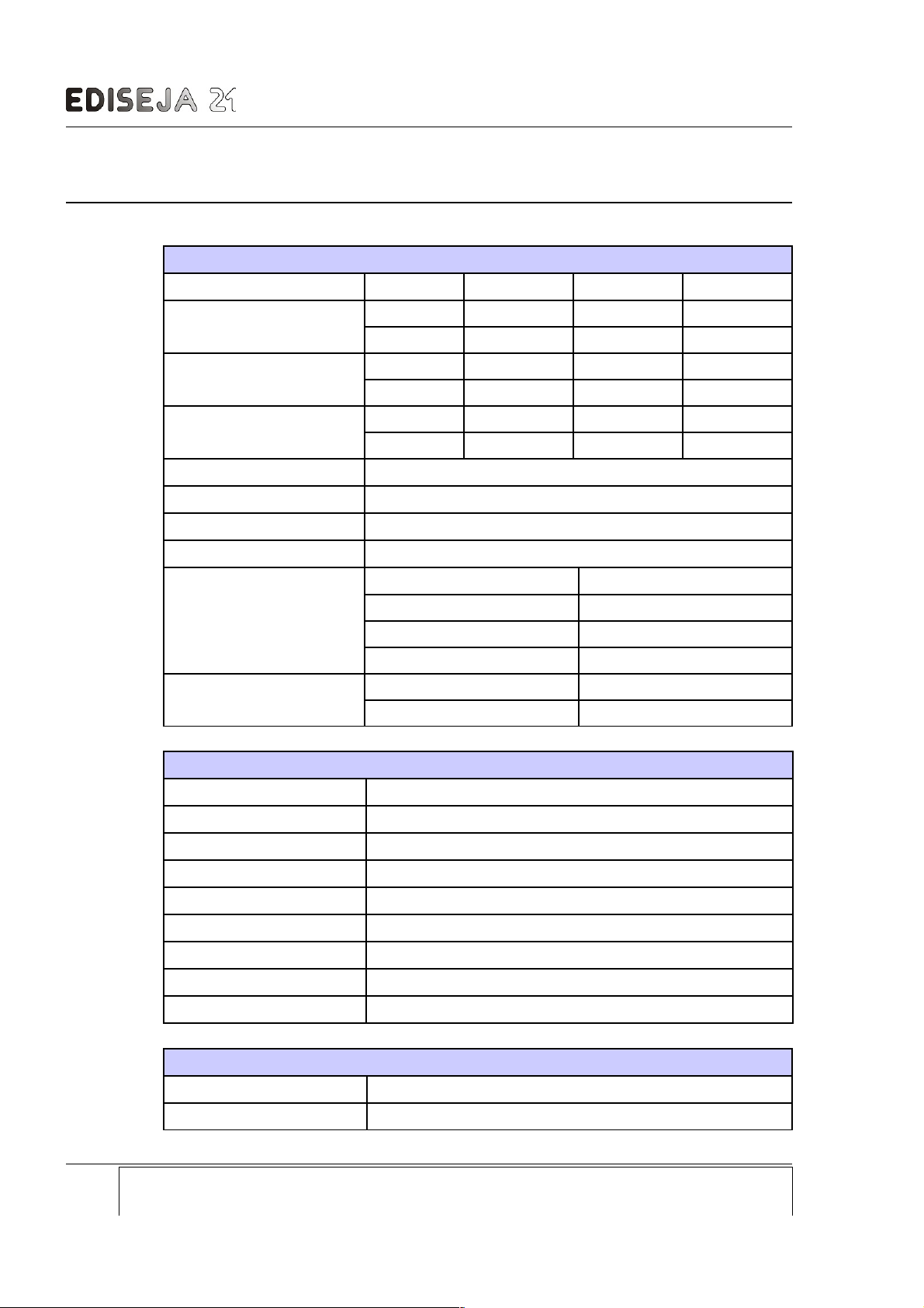
9 TECHNICAL DATA
Power supply
Type HI Type MD Type LO
Rated input voltage
DC 110 - 250 V 48 - 60 V 24 V
AC 230 V 48 V 18 V
Permissible voltage range
DC 88 - 350 V 38 - 72 V 18 - 36 V
AC 70 - 264 V 30 - 50 V 15 - 24 V
Input current
DC 38 - 18 mA 64 - 52 mA 140 mA
AC 20 mA 120 - 80 mA 200 mA
Fuse (internal)
2 A T
Power supply indicator
green LED marked PWR
Voltage dips
20 ms
Connector type
screw type „MSTB“ Phoenix 2pin
Power Supply Wire
crossection 0,5 – 2,5 mm
2
type single or stranded wire
voltage rating 500 V
colour see valid standard
Ground wire
crossection Cu, 2,5 mm
2
colour see valid standard
Communication port RS232 (interface type 232)
Type
RS232
Direction
full duplex
Speed
up to 230 k BAUD
Number of ports
1
Distance
up to 15 m
Isolation
none; (GND earthed)
Connector type
DB9 female
Lines in
1 (RX)
Lines out
1 (TX)
Communication port RS485 (interface type 485, 48M & 48L)
Type
RS485
Direction
half duplex
Page: Company: Device: Document: Code: Date:
32 Ediseja 21 STR 100 User manual STRMUED1 09.08.2019
Page 33
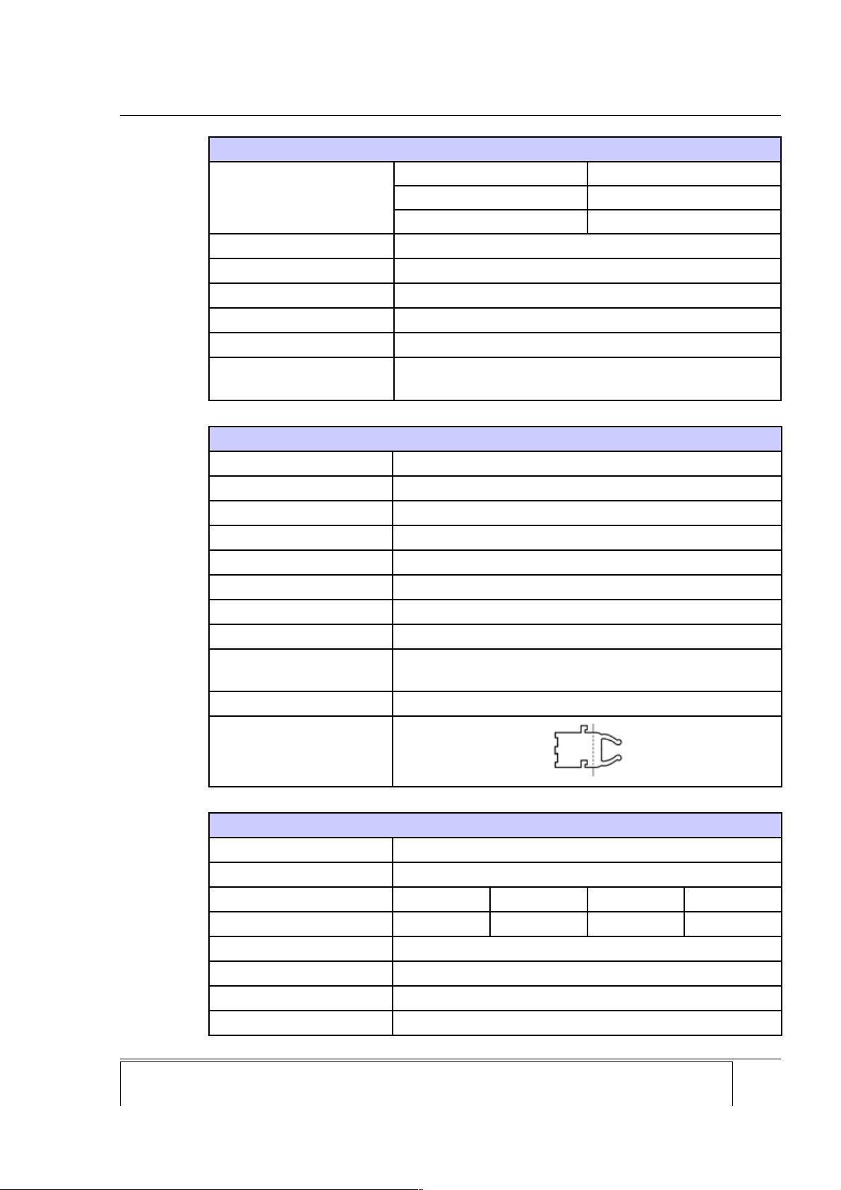
TECHNICAL DATA
Communication port RS485 (interface type 485, 48M & 48L)
Speed
Interface type 485 19200 - 115200 BAUD
Interface type 48M 4800 - 38400 BAUD
Interface type 48L 300 - 2400 BAUD
Number of ports
1
Distance
up to 1200 m
Isolation
1000 V DC
Connector type
„MSTB“ Phoenix 3pin
Termination
120 Ohm
Max number of devices
on BUS
32
Communication port Versatile Link Fiber Optic (interface type FOP)
Type
plastic fiber optic
Wave lenght
660 nm
Fiber size
1 mm diameter plastic optical fiber
Laser class
I (IEC 60825-1) - eye safe
Direction
full duplex
Speed*
up to 40 kbit/s
Input
1 receiver (grey connector)
Output
1 transmitter (black connector)
Logic
light OFF (positive logic) or light ON (negative logic) in idle
state, set by manual switch (see table)
Distance
up to 100 m
Connector type
Communication port Multimode Fiber Optic (interface type FOT)
Type
multimode fiber optic
Wave lenght
820 nm
Fiber size
50/125 μm 62,5/125 μm 100/140 μm 200 μm HCS
Distance (approx.)
600 m 2000 m 1800 m
Optical output power
-18 dB
Reciver sensitivity
-24 dB
Laser class
I (IEC 60825-1)
Direction
full duplex
Company: Device: Document: Code: Date: Page:
Ediseja 21 STR 100 User manual STRMUED1 09.08.2019 33
Page 34
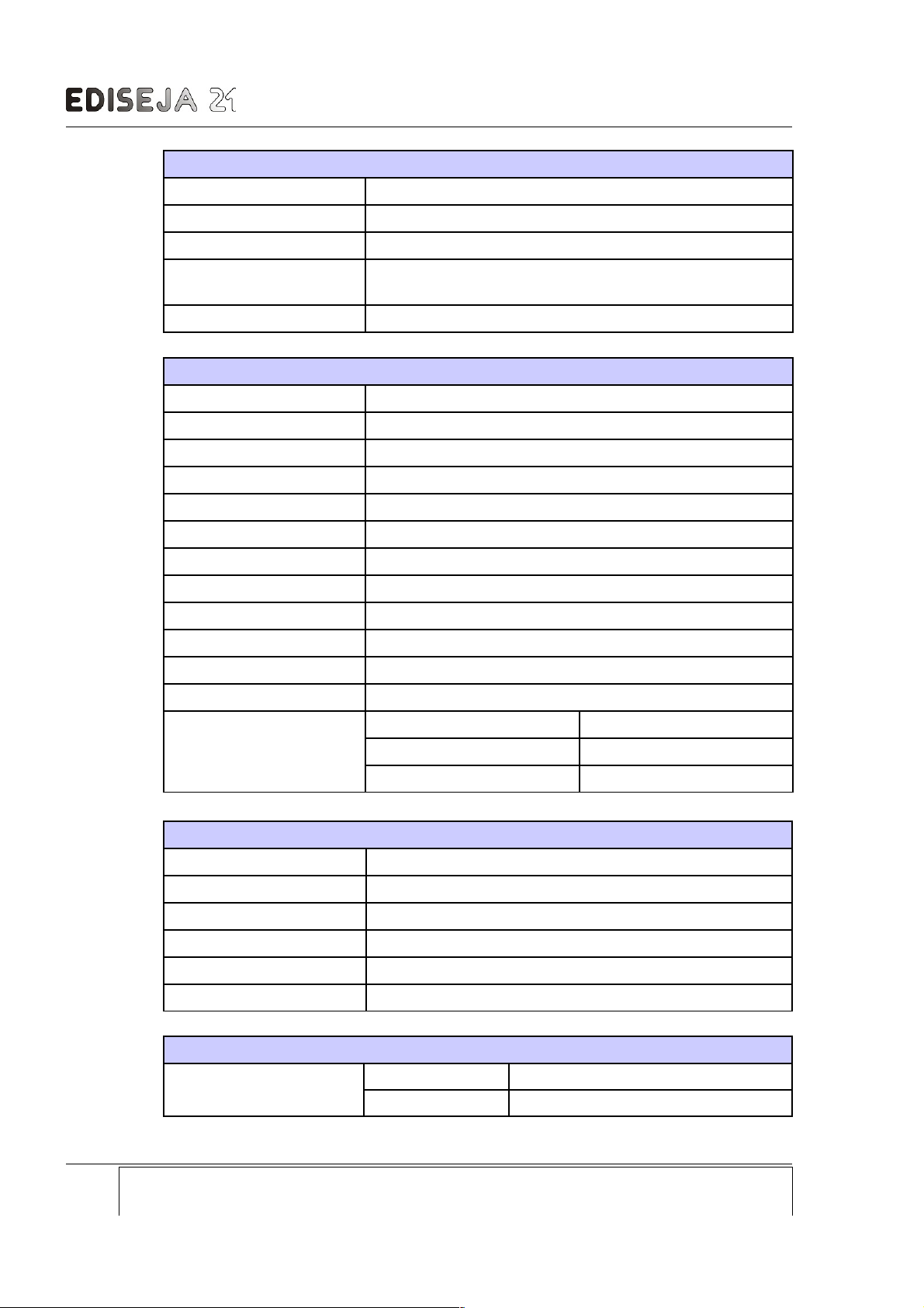
STR 100 - Signal Transducer
Communication port Multimode Fiber Optic (interface type FOT)
Speed
up to 115200 BAUD
Input
1 receiver (grey connector)
Output
1 transmitter (white connector)
Logic
light ON or OFF in idle state set by switch
(see table)
Connector type
ST
Communication port Singlemode Fiber Optic (interface type FOS, FOF & FOU)
Type
singlemode fiber optic
Wave lenght
1310 nm
Fiber size
8-9/125 μm
Optical output power
-7 to 0 dBm
Reciver sensitivity
-18 dBm
Receiver overload
-7 dBm
Laser class
I (IEC 60825-1)
Direction
full duplex
Speed
up to 115200 BAUD
Input
1 receiver
Output
1 transmitter
Distance
up to 20 km
Connector type
CMU 100 / x.x.FOS
SC
CMU 100 / x.x.FOF
FC
CMU 100 / x.x.FOU
ST
Communication port 10/100BASE-TX (interface type ETH)
Type
ethernet
Direction
full duplex
Speed
57600 BAUD
Manufacturer
Lantronix
Type
Xport XP1001000-05R
Link
WWW.lantronix.com
Digital inputs
Input voltage
IOL 24 V DC (+/- 20%)
IO4 and IO4R 48 V DC (+/- 20%)
Page: Company: Device: Document: Code: Date:
34 Ediseja 21 STR 100 User manual STRMUED1 09.08.2019
Page 35
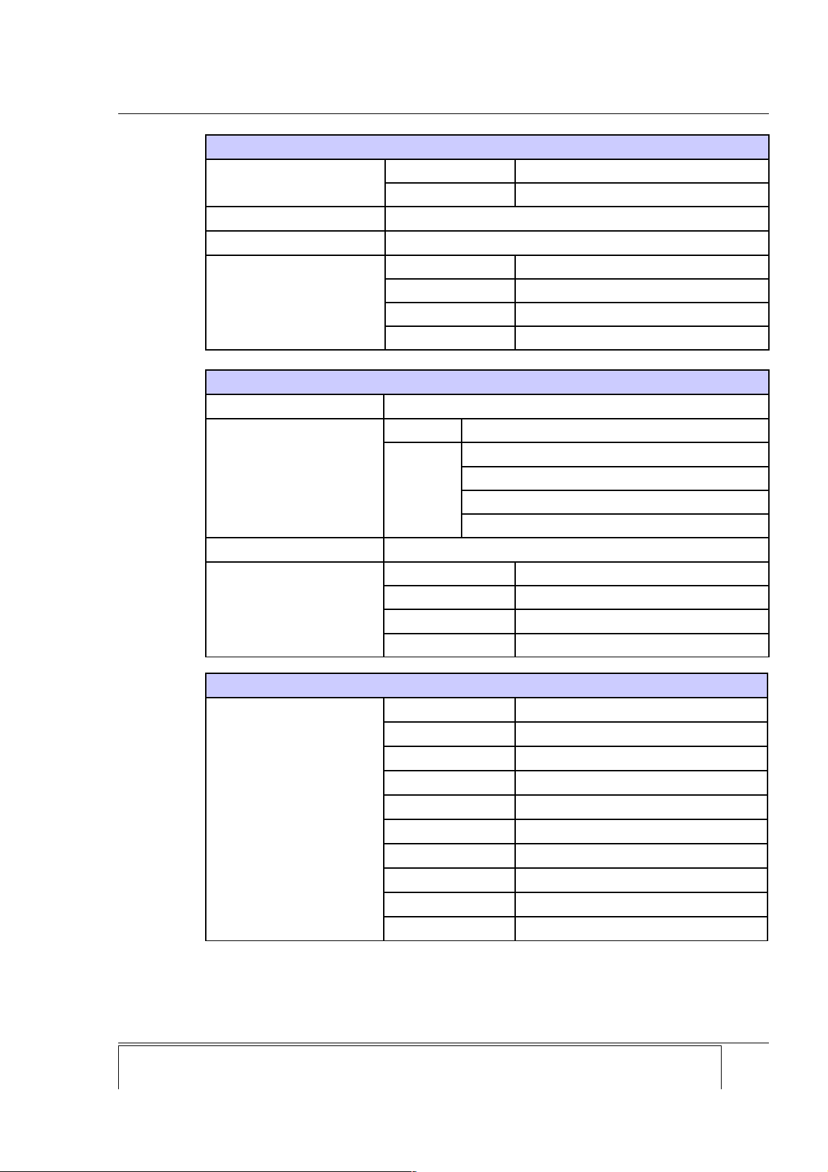
TECHNICAL DATA
Digital inputs
IO1and IO1R 110 V DC (+/- 20%)
IO2 and IO2R 220 V DC (+/- 20%)
Input current
1 mA
Connector type
screw type „MSTB“ Phoenix 16 pin
Wire
crossection 0,5 – 2,5 mm
2
type single or stranded wire
voltage rating 500 V
colour see valid standard
Digital outputs
Max breaking voltage
440 V AC
Max current
AC 5 A at 250 V
DC
5 A at 32 V (resistive bourden)
1,3 A at 48 V (resistive bourden)
0,4 A at 110 V (resistive bourden)
0,35 A at 220 V (resistive bourden)
Connector type
screw type „MSTB“ Phoenix 16 pin
Wire
crossection 0,5 – 2,5 mm
2
type single or stranded wire
voltage rating 500 V
colour see valid standard
Communication speed vs transmission time
Transition time
1200 BAUD
110 ms
2400 BAUD
61 ms
4800 BAUD
34 ms
9600 BAUD
20 ms
14400 BAUD
14 ms
19200 BAUD
13 ms
38400 BAUD
10 ms
57600 BAUD
9 ms
76800 BAUD
8 ms
115200 BAUD
7 ms
Valid for devices except STR 100/x.ETH.x.x. For device STR 100/x.ETH.x.x transition time
depends on network latency.
Company: Device: Document: Code: Date: Page:
Ediseja 21 STR 100 User manual STRMUED1 09.08.2019 35
Page 36
STR 100 - Signal Transducer
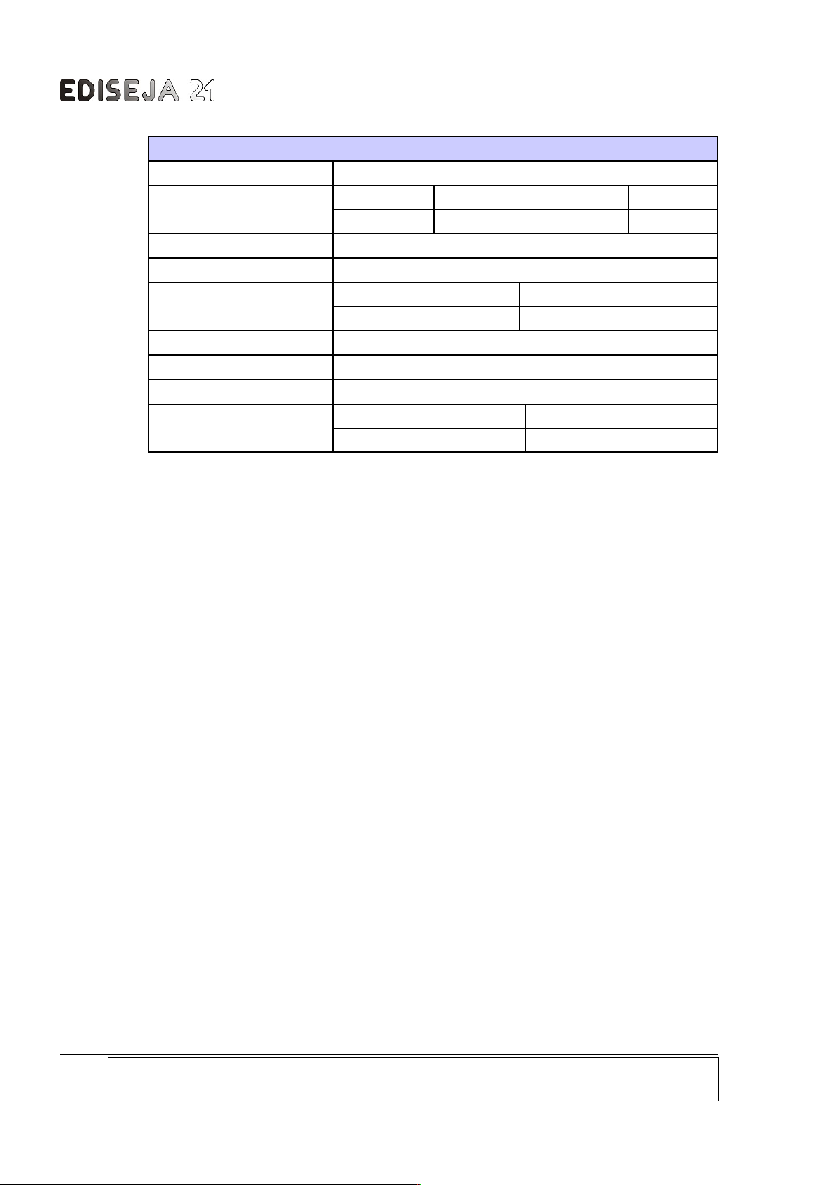
Device
Weight
0,35 kg
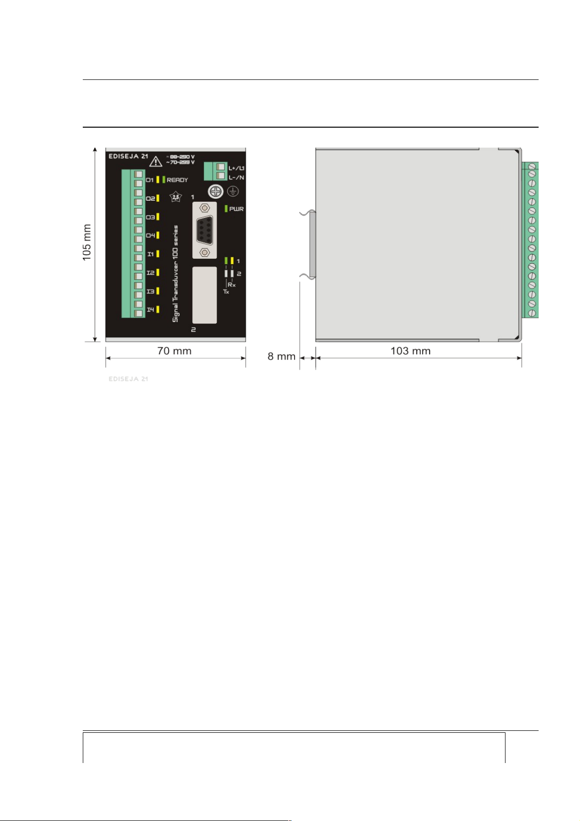
Dimensions
(see picture)
(H) (D) (W)
105 mm 111 mm + connectors 70 mm
Temperature range
0 °C to +55 °C
Humidity operating
up to 95 % (noncondensing)
Enclosure
Material Al
IP 20
Mount type
standard DIN 35 rail (acc. to DIN EN 50022-35)
Class
I
Overvoltage category
II
Communication indicator
Receiveing yellow LED marked Rx
Tranmitting green LED marked Tx
Page: Company: Device: Document: Code: Date:
36 Ediseja 21 STR 100 User manual STRMUED1 09.08.2019
Page 37
DIMENSIONS
10 DIMENSIONS
Company: Device: Document: Code: Date: Page:
Ediseja 21 STR 100 User manual STRMUED1 09.08.2019 37
Picture 25: Dimensions
Page 38
STR 100 - Signal Transducer
11 ORDERING
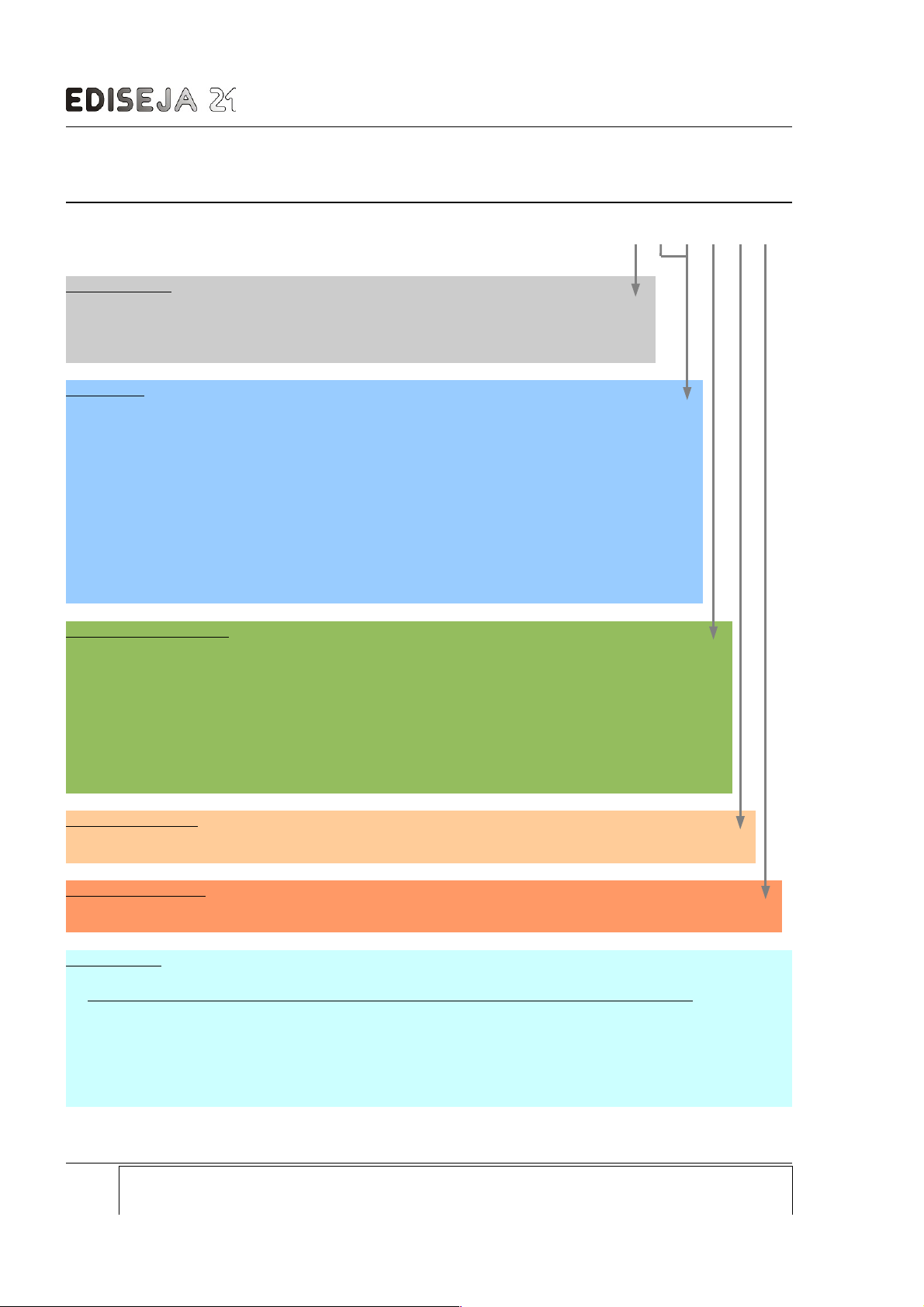
ORDERING NUMBER: STR 100 / c . c . c . c - c . c
Power supply:
110 - 250 V DC or 230 V AC................................................................................ HI
48 - 60 V DC or 48 V AC ................................................................................... MD
24 V DC .............................................................................................................. LO
Interfaces:
none (mark second interf. with „NON“ in case that second interf. is not needed) ................ NON
RS232 (15 m) ............................................................................................................... 232
RS485 isolated, half duplex (1200 m, 19200 - 115200 BAUD) ................................... 485
RS485 isolated, half duplex (1200 m, 4800 - 38400 BAUD) ....................................... 48M
RS485 isolated, half duplex (1200 m, 300 - 2400 BAUD) ........................................... 48L
Versatile (650 nm) fiber optic for 1 mm plastic connector (~110 m) .......................... FOP
Multimode (820 nm) fiber optic with ST connector (~2000 m) .................................... FOT
Singlemode (1310 nm) fiber optic with SC connector (~20 km) ................................. FOS
Singlemode (1310 nm) fiber optic with FC connector (~20 km) ................................. FOF
Singlemode (1310 nm) fiber optic with ST connector (~20 km) ................................. FOU
10/100Base-Tx (Ethernet) .......................................................................................... ETH
Digital input & output:
4 DI (24 V DC), 4 DO (250 V AC, 5 A) ................................................................................ IOL
4 DI (48 V DC), 4 DO (250 V AC, 5 A) ................................................................................ IO4
4 DI (110 V DC), 4 DO (250 V AC, 5 A) .............................................................................. IO1
4 DI (220 V DC), 4 DO (250 V AC, 5 A) .............................................................................. IO2
4 DI (24 V DC), 3 + 1 ready DO (250 V AC, 5 A)............................................................... IOLR
4 DI (48 V DC), 3 + 1 ready DO (250 V AC, 5 A)............................................................... IO4R
4 DI (110 V DC), 3 + 1 ready DO (250 V AC, 5 A) ............................................................ IO1R
4 DI (220 V DC), 3 + 1 ready DO (250 V AC, 5 A) ............................................................ IO2R
Software Version:
software version .......................................................................................................... leave empty
Software Revision:
software revision ................................................................................................................ leave empty
Accessories:
Description
- power supply cable with „schuko“ plug, 2 m
- communication cable RS232 port to PC, 2 m
- fiber optic cable ST-ST connector, 2 m
For other cable lenghts please contact us.
Page: Company: Device: Document: Code: Date:
38 Ediseja 21 STR 100 User manual STRMUED1 09.08.2019
Page 39

ORDERING
Contact:
Ediseja 21 d.o.o.
Stegne 21C
1000 Ljubljana
Slovenia – EU
Tel: 00 386 51 643 411, 051 643 411
www.ediseja21.com
Company: Device: Document: Code: Date: Page:
Ediseja 21 STR 100 User manual STRMUED1 09.08.2019 39
 Loading...