

Page 1
CAX1800
User Manual
11-2019 / v1.0
Page 2

Contents
I. Product Information .................................................... 1
I-1. Package Contents .................................................................. 2
I-2. System Requirements ............................................................ 4
I-3. Hardware Overview .............................................................. 4
I-4. LED Status ............................................................................. 5
II. Hardware Installation ................................... 6
III. Quick Setup (AP Mode) ................................14
IV. Basic Settings ...............................................16
IV-1. Changing IP Address ............................................................ 17
IV-2. Changing SSID For 2.4GHz Wireless Networ ......................... 18
IV-3. Configuring Security Settings of 2.4GHz wireless network .... 19
IV-4. Changing Security Setting for 5GHz wireless network .......... 21
IV-5. Changing Admin Name and Password ................................. 22
IV-6. Changing Date and Time ..................................................... 22
V. CAX1800 Settings .........................................23
V-1. Information ......................................................................... 23
i. System Information ............................................................. 24
ii. Wireless Clients ................................................................... 27
iii. Wireless Monitor ................................................................. 28
Page 3

iv. DHCP Clients ........................................................................ 29
v. Log ...................................................................................... 29
V-2. Network Settings ................................................................. 31
i. LAN-side IP Address ............................................................. 31
ii. LAN Port .............................................................................. 34
iii. IGMP Snooping .................................................................... 35
iv. STP Management ................................................................ 35
v. VLAN ................................................................................... 36
V-3. Wireless Settings ................................................................. 37
i. Basic (2.4GHz 11bgn) ........................................................... 38
ii. Advanced (2.4GHz 11bgn) ................................................... 41
iii. Security (2.4GHz 11bgn) ...................................................... 44
iv. WDS (2.4GHz 11bgn) ........................................................... 46
v. Guest Network (2.4GHz 11bgn) ........................................... 48
vi. 5GHz 11ac 11an ................................................................... 48
vii. WPS .................................................................................... 49
viii. RADIUS (RADIUS Settings) .............................................. 49
ix. Internal Server ..................................................................... 51
x. RADIUS Accounts ................................................................. 53
xi. MAC Filter ........................................................................... 55
xii. WMM .................................................................................. 57
Page 4

xiii. Schedule ......................................................................... 59
xiv. Traffic Shaping ............................................................... 61
xv. Bandsteering ....................................................................... 62
V-4. Management ...................................................................... 63
i. Admin ................................................................................. 64
ii. Date and Time ..................................................................... 66
iii. Syslog Server ....................................................................... 67
iv. Ping Test ............................................................................. 69
v. Traceroute Test ................................................................... 70
V-5. Advanced ............................................................................ 71
i. LED Settings ........................................................................ 71
ii. Update Firmware ................................................................ 72
iii. Save / Restore Settings ........................................................ 73
iv. Factory Default .................................................................... 74
v. Reboot ................................................................................ 75
V-6. Operation Mode .................................................................. 76
VI. Edimax Pro NMS ..........................................77
VI-1. Quick Setup – NMS ......................................................... 78
VI-2. Webpage Layout - NMS ....................................................... 85
VI-3. NMS Features ...................................................................... 92
VI-4. Dashboard ........................................................................... 94
Page 5

i. System Information ............................................................. 95
ii. Devices Information ............................................................ 95
iii. Managed AP........................................................................ 96
iv. Managed AP Group ............................................................. 98
v. Active Clients ..................................................................... 101
vi. Active Users ....................................................................... 101
VI-5. Zone Plan .......................................................................... 102
ii. Control .............................................................................. 106
VI-6. NMS Monitor ..................................................................... 108
i. AP …………………………………………………………………………………..108
ii. Managed AP Group ........................................................... 111
iii. WLAN ................................................................................ 114
iv. Clients ............................................................................... 116
v. Users ................................................................................. 117
vi. Rogue Devices ................................................................... 118
vii. Information ....................................................................... 119
VI-7. NMS Settings ..................................................................... 123
i. Access Point ...................................................................... 123
ii. WLAN ................................................................................ 140
iii. RADIUS .............................................................................. 145
iv. Access Control ................................................................... 153
Page 6

v. Guest Network .................................................................. 156
vi. Users ................................................................................. 160
vii. Guest Portal ...................................................................... 161
viii. Zone Edit ...................................................................... 171
ix. Schedule ............................................................................ 173
x. Smart Roaming ................................................................. 174
xi. Device Monitoring ............................................................. 175
xii. Firmware Upgrade ............................................................ 176
xiii. Advanced ..................................................................... 177
VI-8. Local Network ................................................................... 179
i. Network Settings ............................................................... 179
ii. 2.4GHz 11bgn .................................................................... 184
iii. 5GHz 11ac 11an ................................................................. 199
iv. WPS .................................................................................. 209
v. RADIUS .............................................................................. 211
vi. MAC Filter ......................................................................... 216
vii. WMM ................................................................................ 218
viii. Schedule ....................................................................... 220
VI-9. Local Settings .................................................................... 222
i. Operation Mode ................................................................ 222
ii. Management .................................................................... 230
Page 7

iv. Advanced .......................................................................... 235
VI-10. Toolbox ............................................................................. 240
i. Network Connectivity ........................................................ 240
VII. WPS ........................................................... 242
VIII. Reset .......................................................... 244
Page 8
I. Product Information
The CAX1800 with the latest emerging IEEE 802.11ax Wi-Fi 6 technology
effortlessly create a reliable internet connection. Place the CAX1800 between
the router and the location where you need better wireless coverage and
enjoy high-speed wireless connection throughout your home or office.
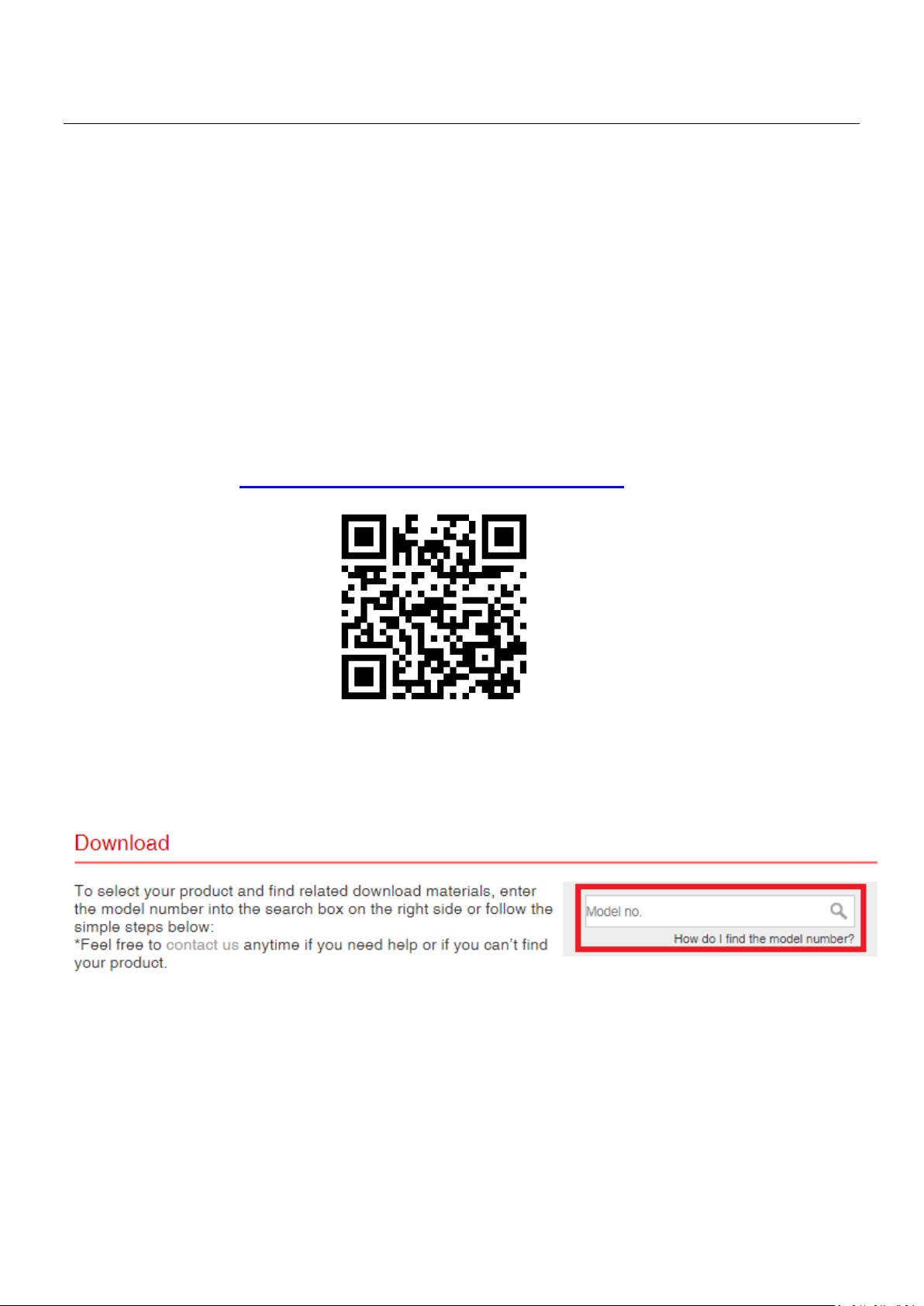
You can find all supporting documents from the link below or via QR Code:
https://www.edimax.com/download
(Once you’ve visited the Edimax official website, please enter the model no.
“CAX1800” into the search box to search for your product.)
1
Page 9

I-1. Package Contents
CAX1800
Ceiling Mount Bracket
Ethernet Cable
Ceiling Mount Screw Template
Manual
T-Rail Mounting Kit & Screws
2
Page 10
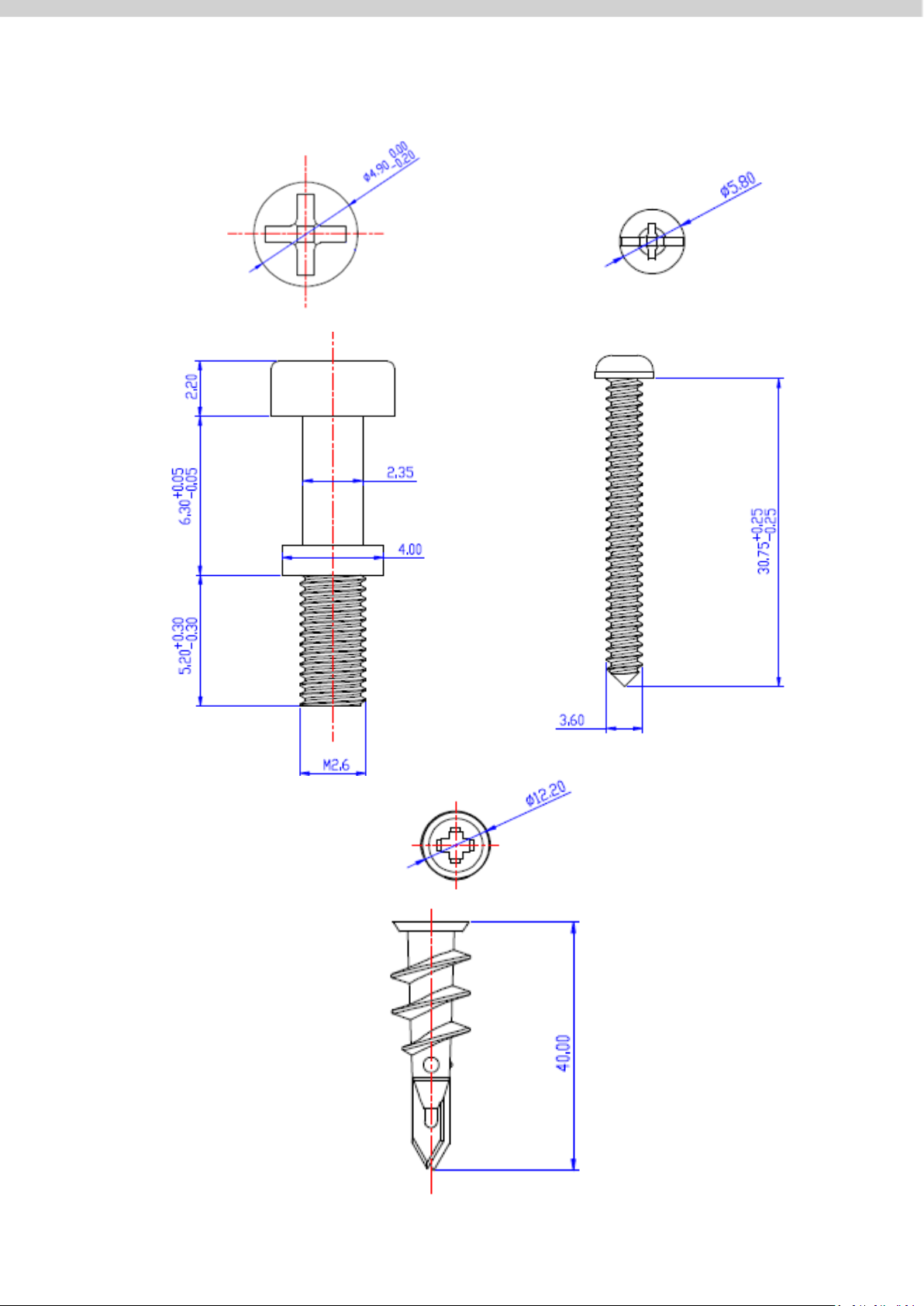
Screws Size:
3
Page 11
I-2. System Requirements
3
4
- Existing cable/DSL modem & router
- Computer with web browser for AP configuration
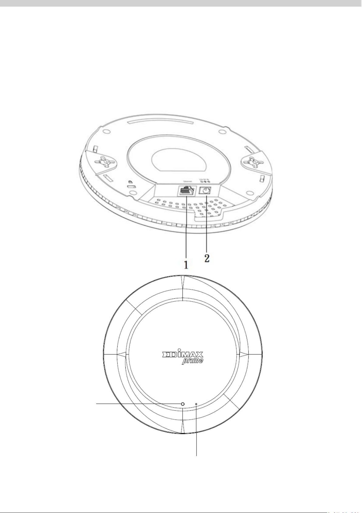
I-3. Hardware Overview
4
Page 12

No.
Description
1
Ethernet Port (PoE)
2
Power Jack (12V/1.5A)
3
Reset Button
4
LED
Color
Status
Description
Blue
On
Power is on.
Flashing Slowly
Upgrading firmware.
Flashing Quickly
Resetting to factory defaults.
Red
On
Starting up.
Flashing
Error.
Off
Off
Power is off.
I-4. LED Status
5
Page 13
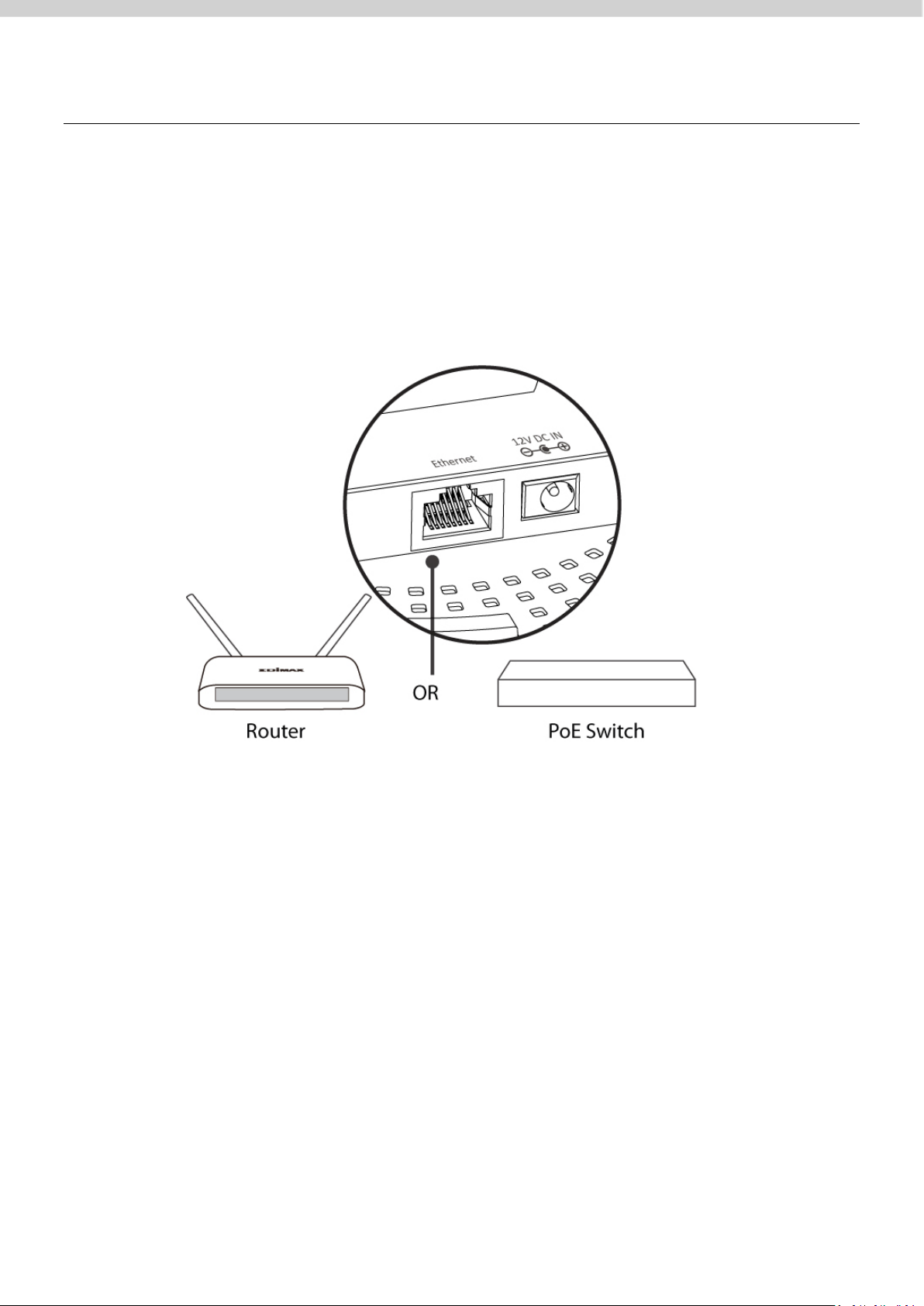
II. Hardware Installation
This section will guide you through the steps to set up your CAX1800.
Router or Switch:
Connect the AP to a router or a PoE switch using an Ethernet cable.
6
Page 14
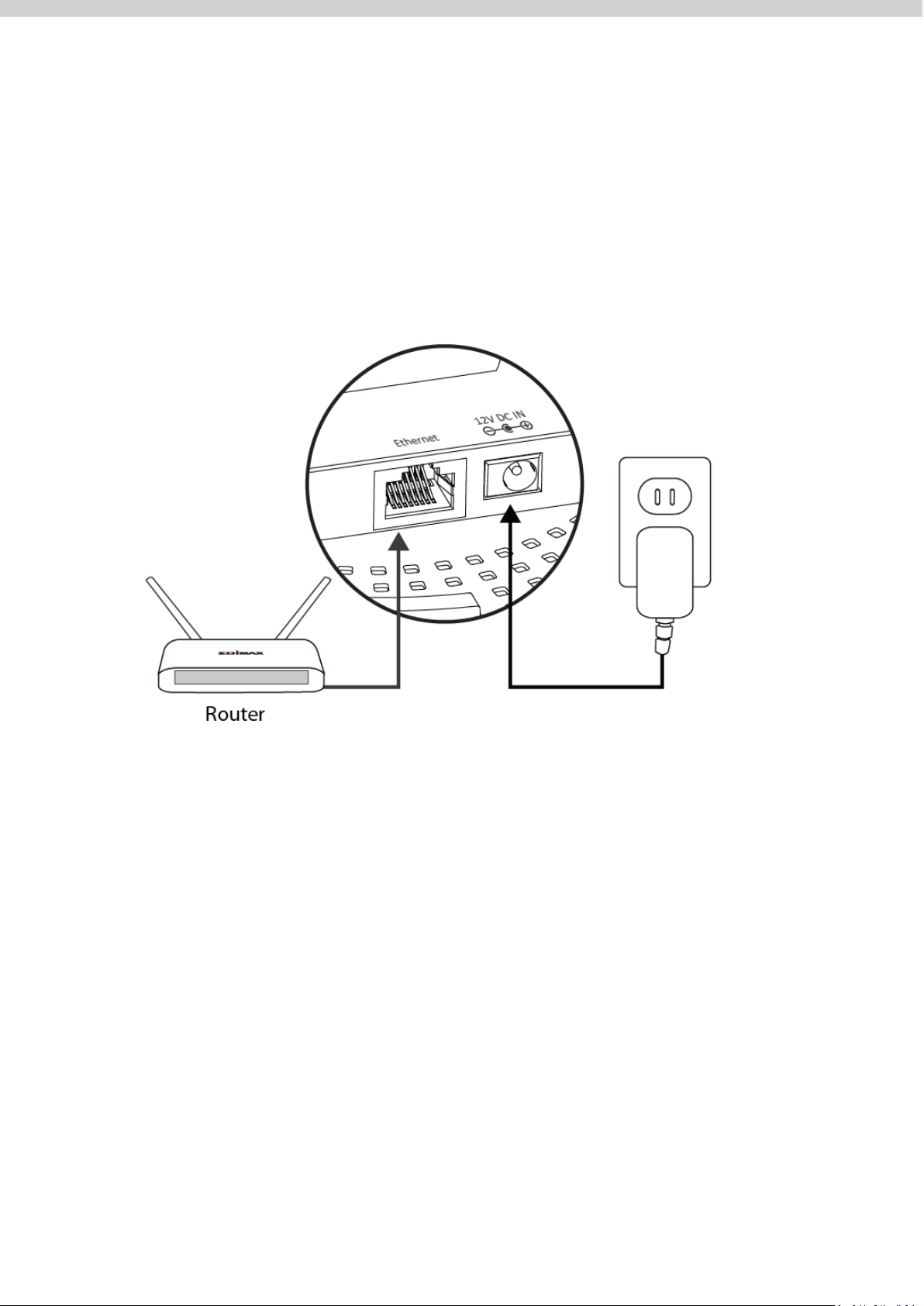
II-1. Connect AP to a router
If router is used, connect the power adapter to the AP and plug the power
adapter into a power supply. Please wait a moment for the AP to start up. The
AP is ready when the LED is Blue.
7
Page 15
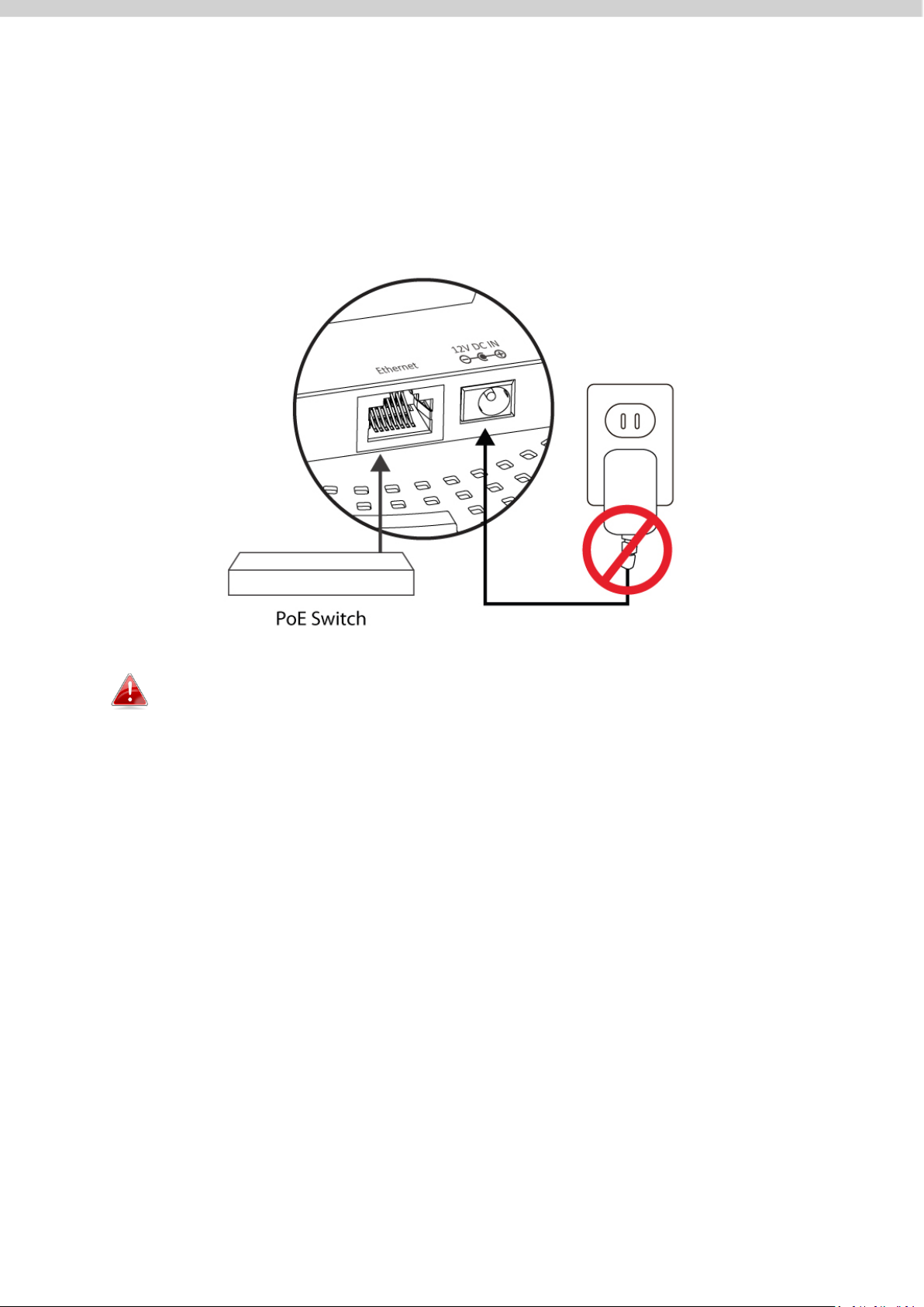
II-2. Connect AP to a switch
If PoE switch is used, make sure the Ethernet cable is connected to Ethernet
port from the PoE switch. The AP will be powered by the switch.
Please wait a moment for the AP to start up. The AP is ready when the LED is
Blue.
Do not use the power adapter if you are using a PoE switch.
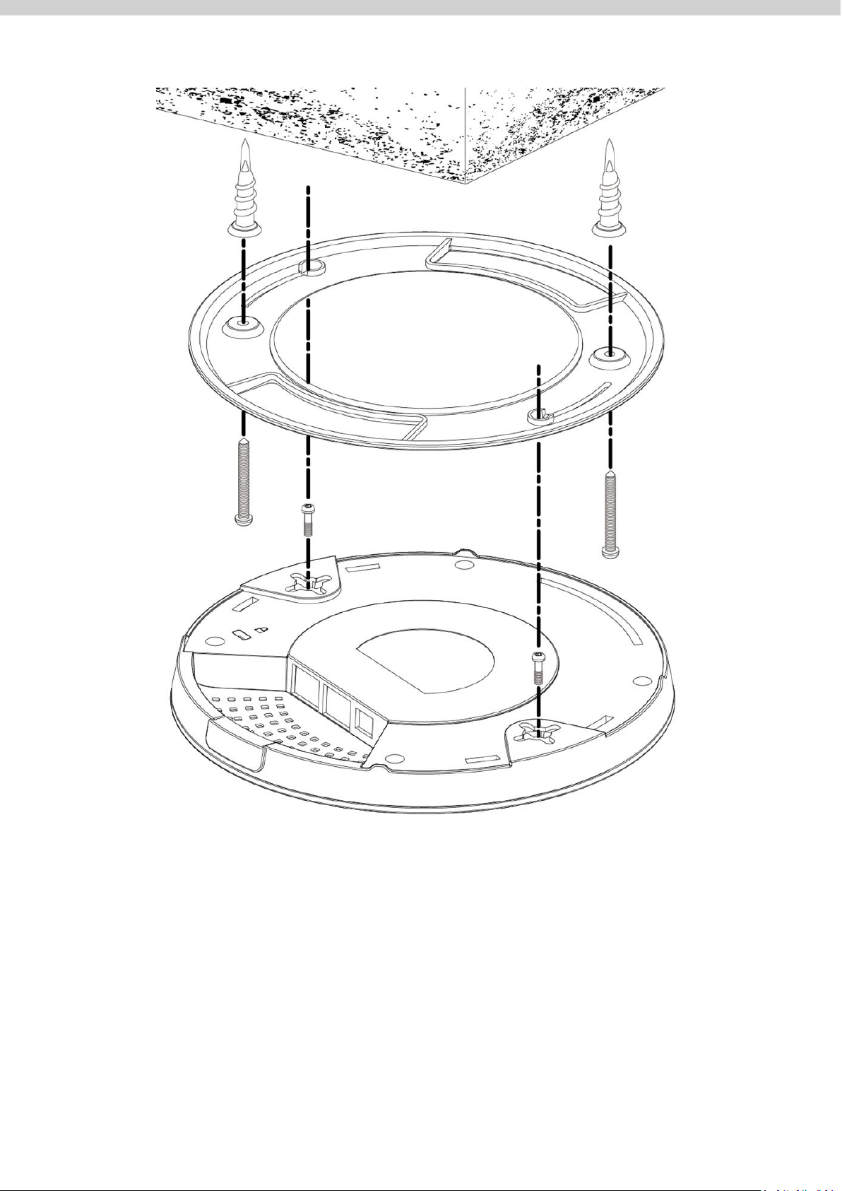
II-3. Mounting
To mount the device to a ceiling, please follow the instructions below and
refer to diagram A & B.
Wooden Ceiling:
Please refer to the figure below:
1. By using the holes A on the ceiling bracket, identify and mark correct
screw positions of the desired mounting location.
2. Where necessary, drill a hole (of radius smaller than the radius of the
provided screws) on each of the marked screw positions.
8
Page 16
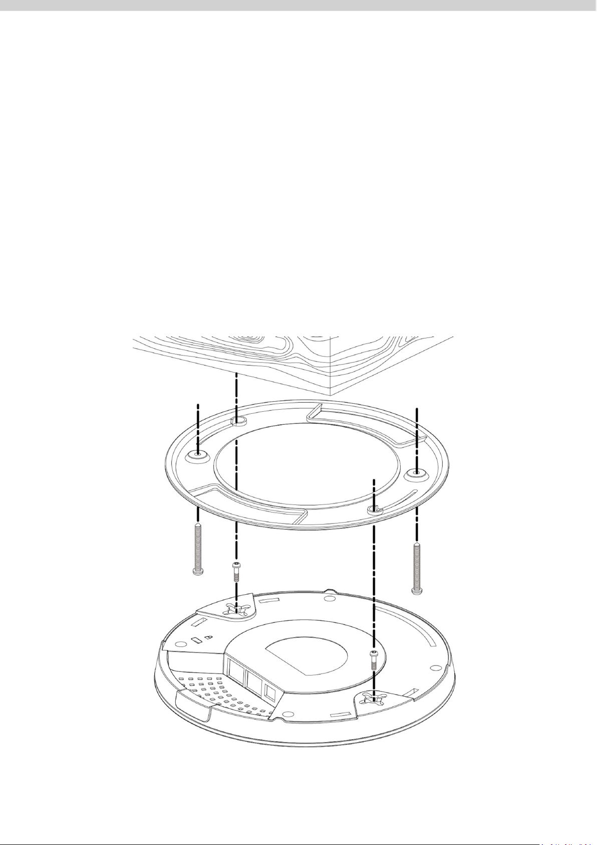
3. Fix the ceiling mount bracket to the desired location by inserting the
A
A
B
B
C
C D D
E E F
F
ceiling fixing screws B through the bracket ceiling holes A. Tighten the
ceiling fixing screws B to the marked screw position using a screw driver
to fix the bracket in place.
4. Fix the bracket rail screws C into the holes D on the device using a
screw driver. The cap of the screws should be protruding outwardly
from the holes D.
5. Insert the bracket rail screws C into the device fixing holes E.
6. Twist the device as the bracket rail screws C slide through the bracket
rail F.
Twist the device all the way until you feel that it is fixed in position.
9
Page 17

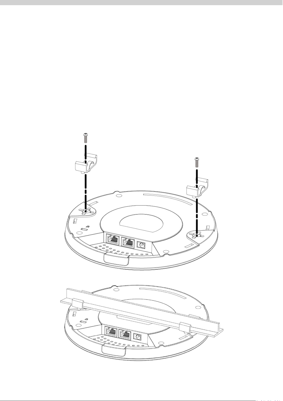
Other Ceiling:
Please refer to the figure below:
1. By using the holes A on the ceiling bracket, identify and mark correct
screw positions of the desired mounting location.
2. Where necessary, drill a hole on each of the marked screw positions.
3. Insert the anchors G into the holes (use a screw driver where necessary)
at the marked screw positions.
4. Fix the ceiling mount bracket to the desired location by inserting the
ceiling fixing screws B through the bracket ceiling holes A. Tighten the
ceiling fixing screws B onto the anchors G using a screw driver to fix the
bracket to the ceiling.
5. Fix the bracket rail screws C into the holes D on the device using a
screw driver. The cap of the screws should be protruding outwardly
from the holes D.
6. Insert the bracket rail screws C into the device fixing holes E.
7. Twist the device as the bracket rail screws C slide through the bracket
rail F.
Twist the device all the way until you feel that it is fixed in position.
10
Page 18
E G G E A A F F B B C C D
D
11
Page 19
T-Rail Mount:
A A C C B B D A A
To mount the device to a T-Rail, please follow the instructions below and refer
to the diagrams below.
1. Select the correct size T-Rail bracket included in the package contents.
2. Attach the selected T-Rail brackets A to holes B using bracket fixing
screws C.
3. Clip the device onto the T-Rail D using the now attached T-Rail brackets
A.
12
Page 20
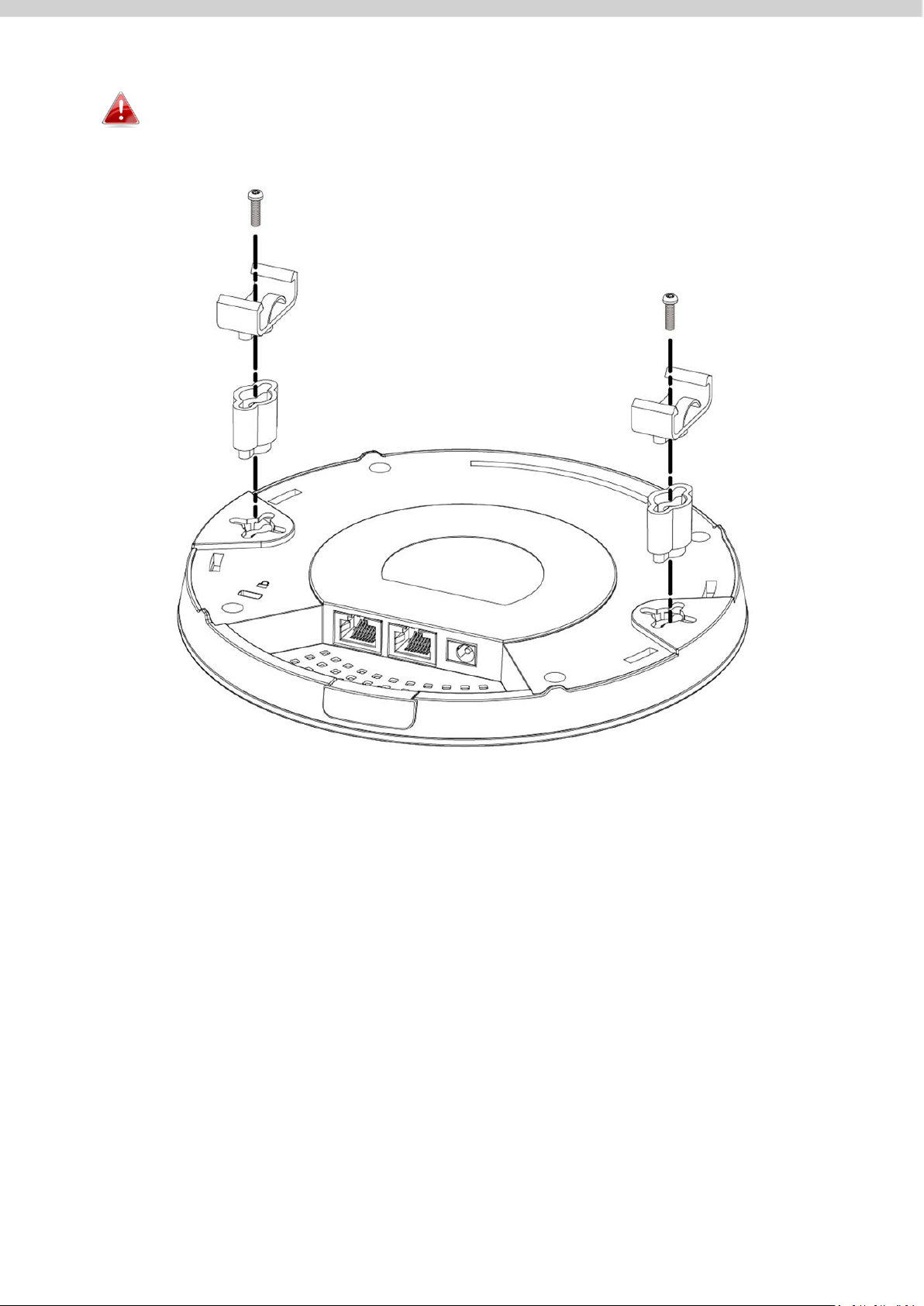
E
E
A
A
If you need more space between the device and the T-Rail,
additional cushion bracket E can be added between T-Rail brackets
A and holes B (use the longer screws included).
13
Page 21
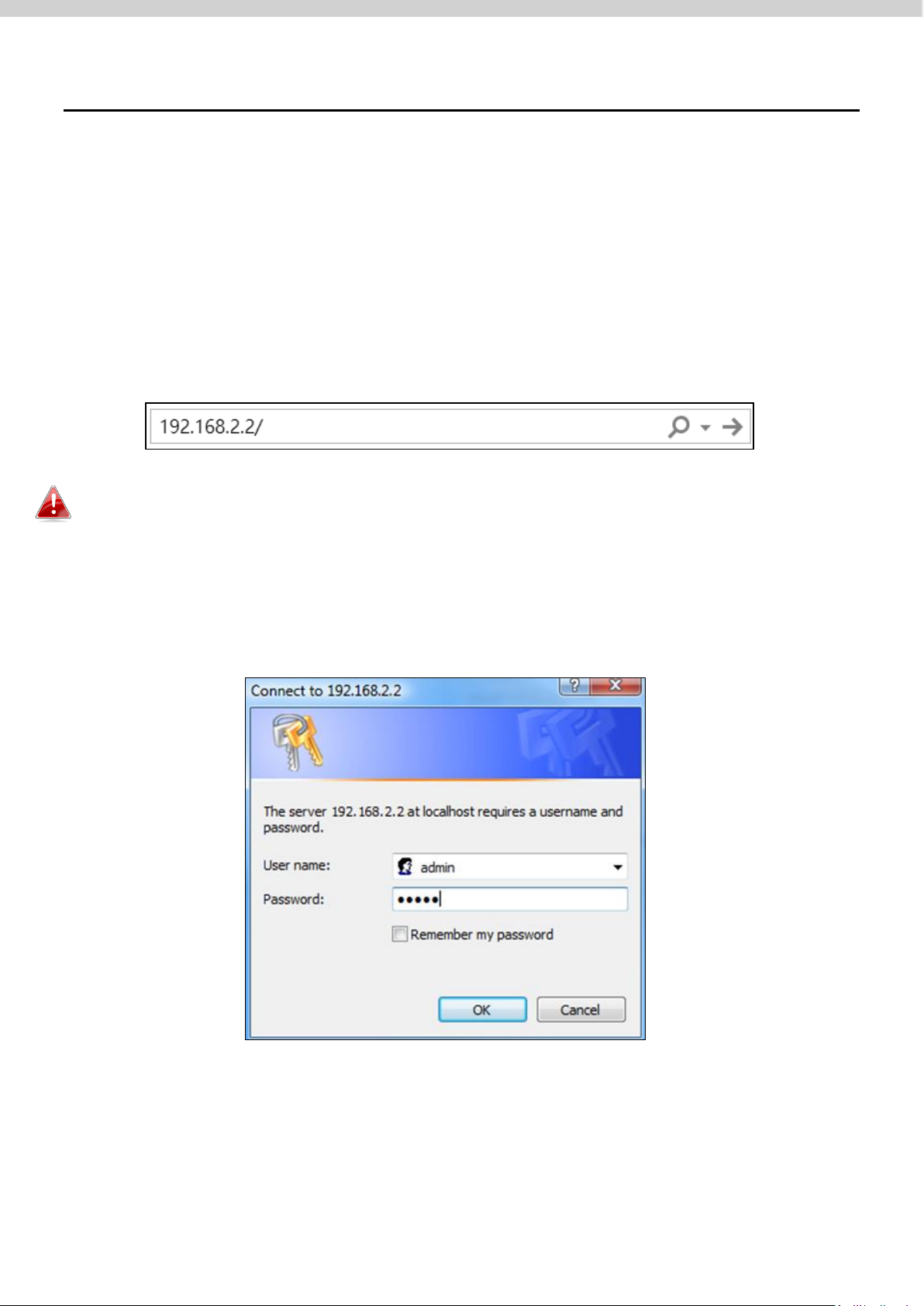
III. Quick Setup (AP Mode)
This quick installation section will help you setup your AP in its default AP
mode and configure its basic settings.
Please follow the steps below:
1. Enter the AP’s default IP address “192.168.2.2” into the URL bar of a web
browser.
Please ensure to set your computer’s IP address to “192.168.2.X” where X
is a number in the range 3 ~ 100.
2. You will be prompted for a username and password. Enter the default
username “admin” and password “1234”.
14
Page 22
3. Home screen will be shown.
15
Page 23
IV. Basic Settings
In our recommendation, please check each of the settings that listed below
before using the AP.
- LAN IP Address
- 2.4GHz & 5GHz SSID & Security
- Administrator Name & Password
- Time & Date
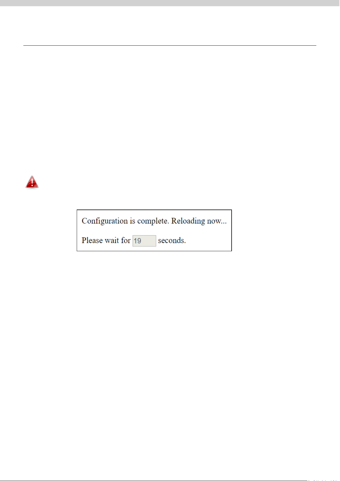
Please note that whenever a new setting is applied to the AP, the
webpage will reload, as shown below:
Please follow the instructions below for the basic settings.
16
Page 24
IV-1. Changing IP Address
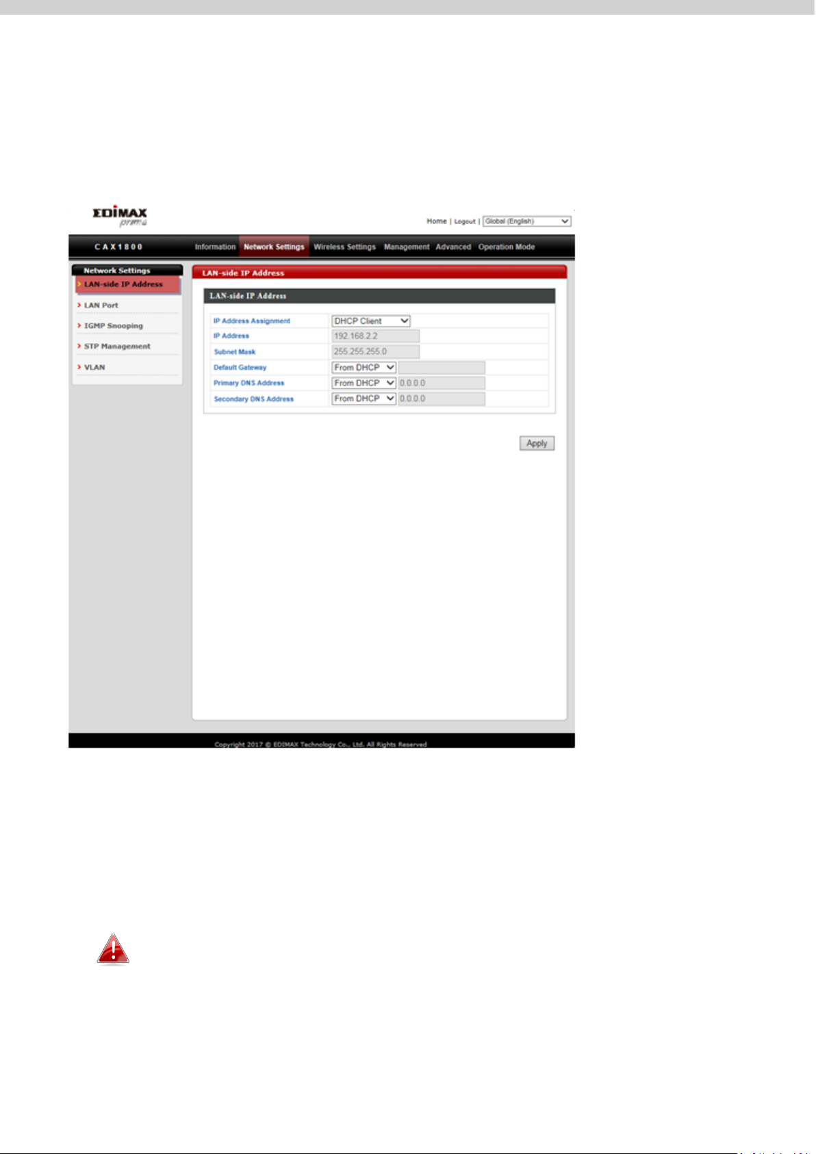
1. Go to “Network Settings” and tap “LAN-side IP Address”.
2. Enter the IP address settings you wish to use for your AP. You can use a
dynamic (DHCP) or static IP address, depending on your network
environment. Click “Apply” to save the changes and wait a few moments
for the AP to reload.
When you change your AP’s IP address, you need to use the new IP
address to access the browser based configuration interface instead
of the default IP 192.168.2.2.
17
Page 25
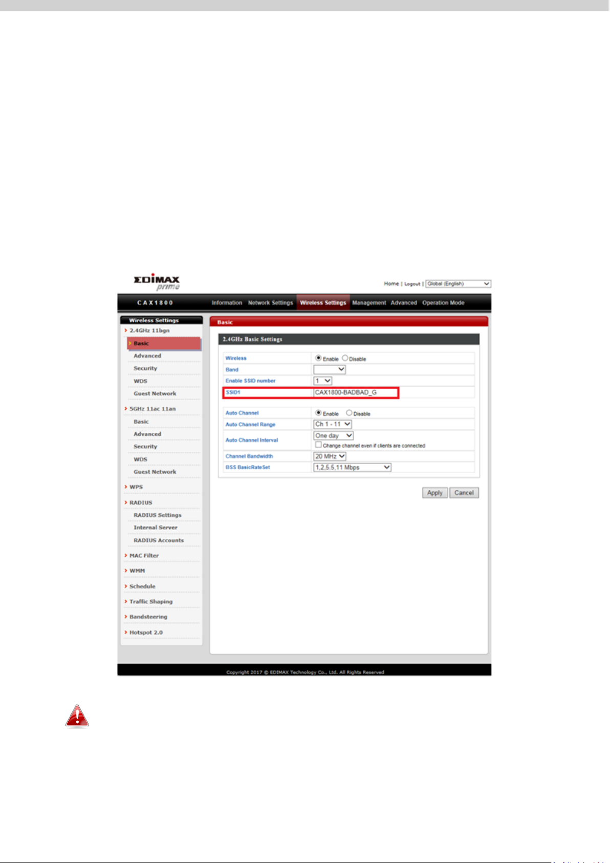
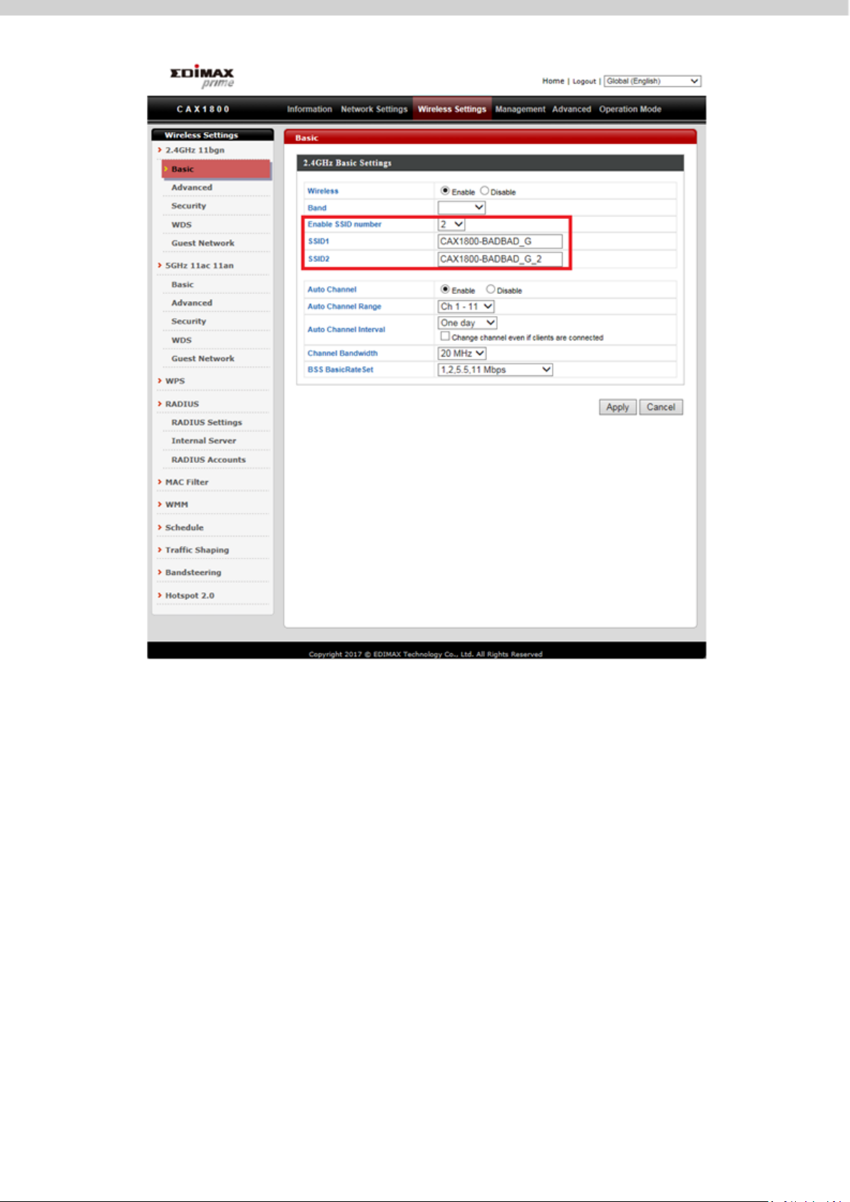
IV-2. Changing SSID For 2.4GHz Wireless Network
1. Go to “Wireless Settings”.
2. Tap “2.4GHz 11bgn”.
3. Tap “Basic”.
4. Enter the new SSID for your 2.4GHz wireless network in the “SSID1”
field and click “Apply”.
To utilize multiple 2.4GHz SSIDs, open the drop down menu labelled
“Enable SSID number” and select how many SSIDs you require. Then
enter a new SSID in the corresponding numbered fields below,
before clicking “Apply”.
18
Page 26
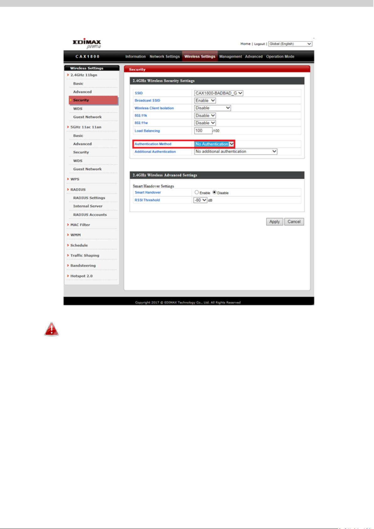
IV-3. Configuring Security Settings of 2.4GHz wireless network
1. Go to “Wireless Settings”.
2. Tap “2.4GHz 11bgn”.
3. Tap “Security”.
4. Select an “Authentication Method”, enter or select fields where
appropriate, and click “Apply”.
19
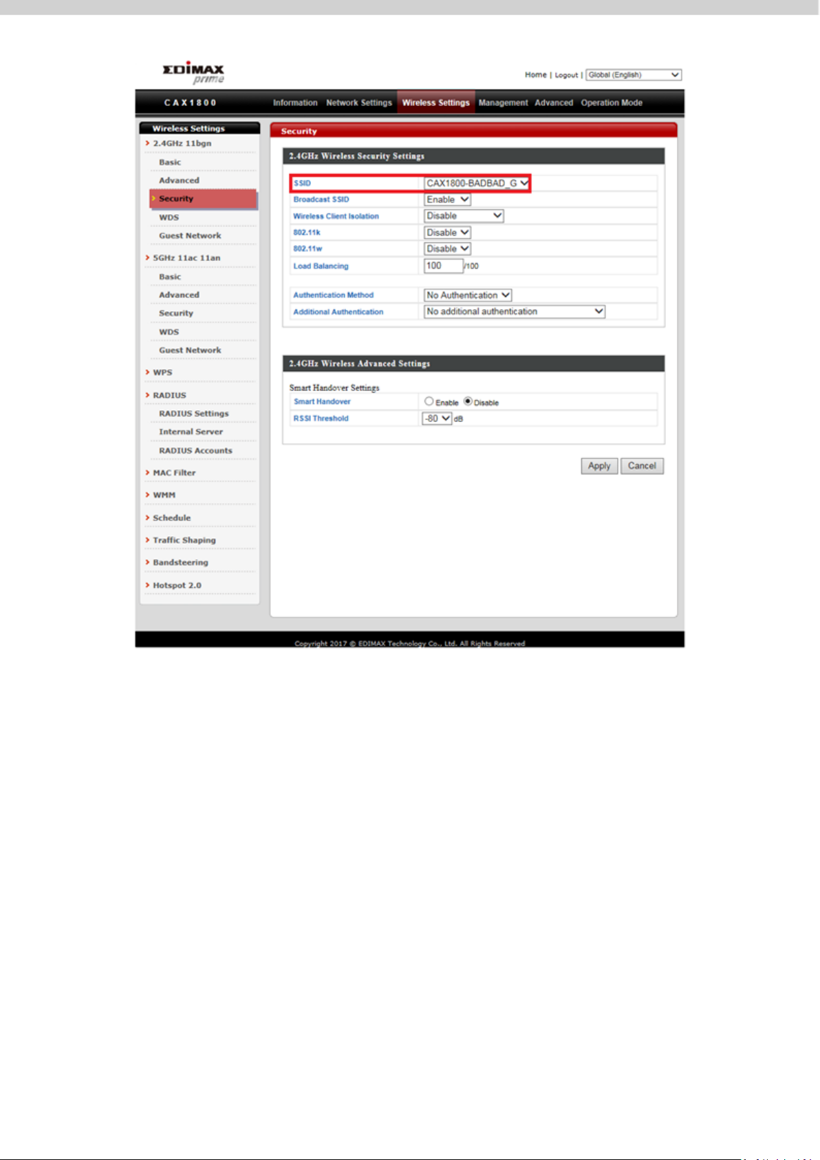
Page 27
If multiple SSIDs are used, specify which SSID to configure using the
“SSID” drop down menu.
20
Page 28
IV-4. Changing Security Setting for 5GHz wireless network
Follow the steps outlined in “Changing SSID for 2.4GHz wireless network” and
“Configuring Security Setting for 2.4GHz wireless network” but choose the
5GHz option instead.
21
Page 29
IV-5. Changing Admin Name and Password
1. Go to “Management”.
2. Tap “Admin”.
3. Complete the “Administrator Name” and “Administrator Password”
fields and click “Apply”.
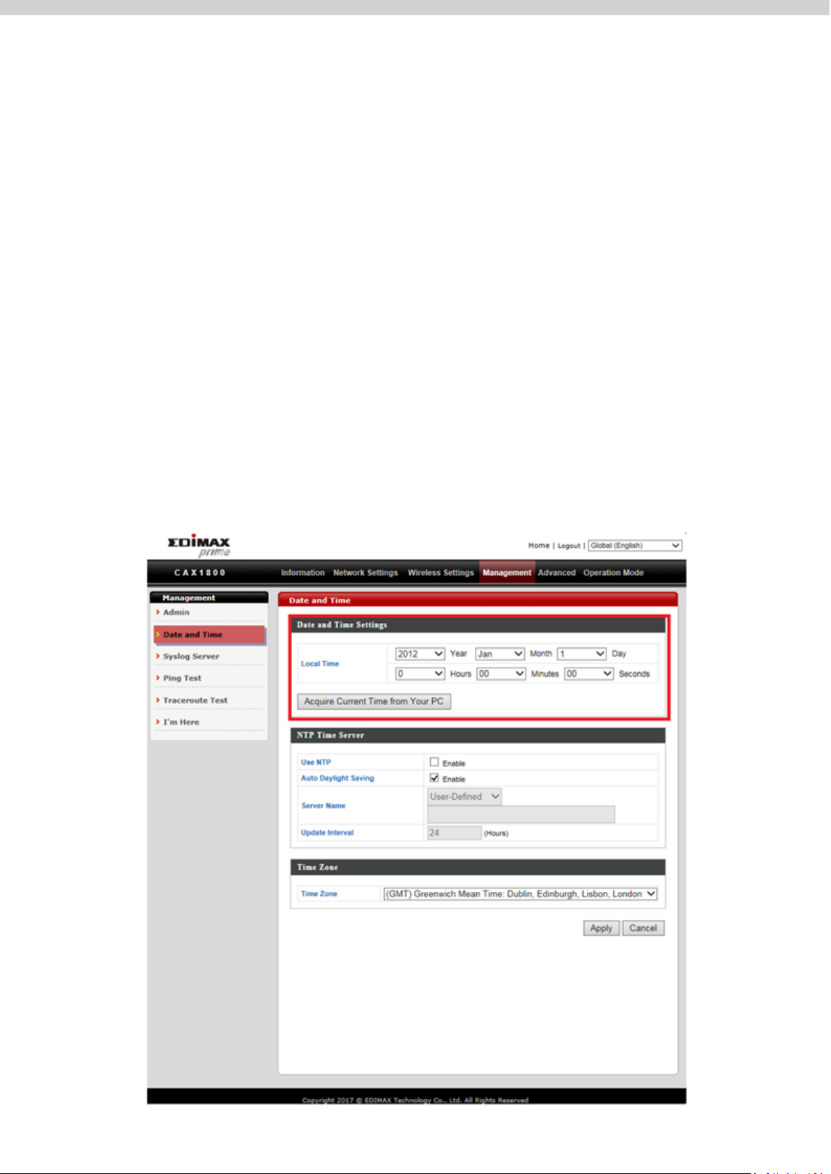
IV-6. Changing Date and Time
1. Go to “Management”.
2. Tap “Date and Time”.
22
Page 30
3. Set the correct time and time zone for your AP using the drop down
menus. The AP also supports NTP (Network Time Protocol).
Alternatively, you can enter the host name or IP address of a time
server. Click “Apply” when you are finished.
You can use the “Acquire Current Time from Your PC” button if you
wish to set the AP to the same time as your PC.
Congrats! The basic settings of your AP are now configured and your AP is up
and running!
V. CAX1800 Settings
The CAX1800 features a range of advanced functions. Please open a browser
and enter the CAX1800 default IP address “192.168.2.2” to access the AP
configuration webpage.
V-1. Information
23
Page 31

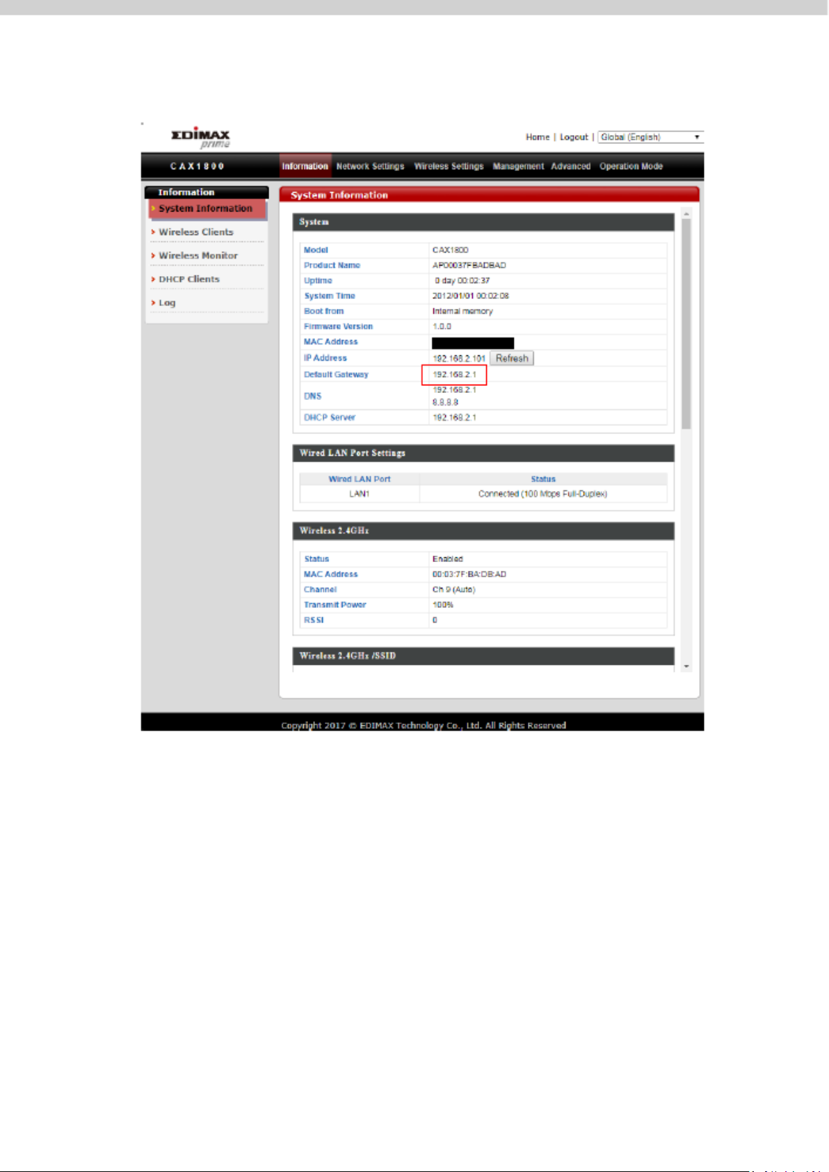
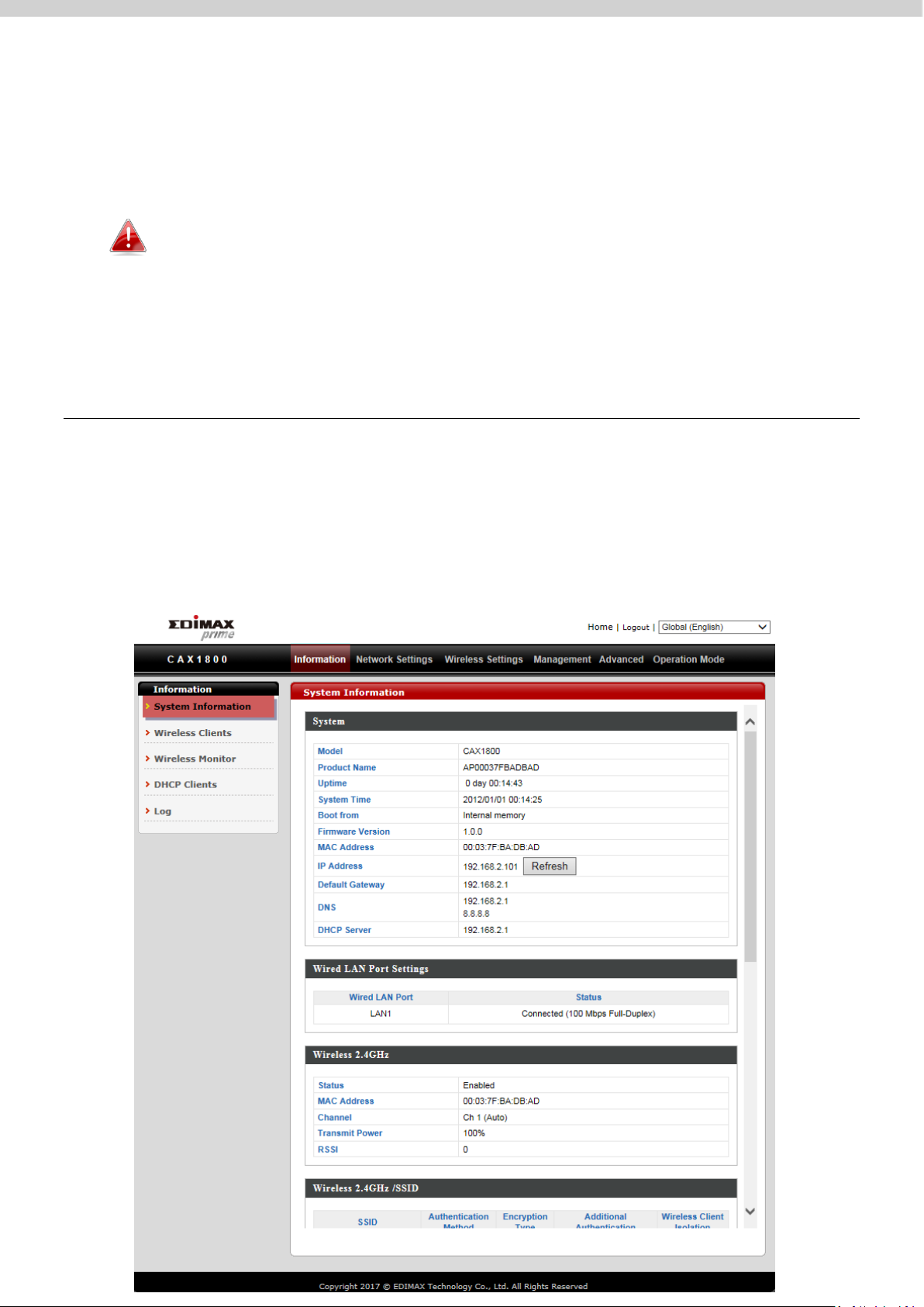
i. System Information
“System Information” page displays basic system information.
24
Page 32

System
Model
Displays the model number of the AP.
Product Name
Displays the product name for reference, which consists of
“AP” plus the MAC address.
Uptime
Displays the total time since the device was turned on.
System Time
Displays the system time.
Boot From
Displays information for the booted hardware, booted from
internal memory.
Firmware
Version
Displays the firmware version.
MAC Address
Displays the AP’s MAC address.
Management
VLAN ID
Displays the management VLAN ID.
IP Address
Displays the IP address of this device.
(Click “Refresh” to update this value)
Default
Gateway
Displays the IP address of the default gateway.
DNS
IP address of DNS
(Domain Name Server)
DHCP Server
IP address of DHCP Server.
Wired LAN Port Settings
Wired LAN
Port
Specifies which LAN port.
Status
Displays the status of the specified LAN port.
(Connected or disconnected)
VLAN Mode/ID
Displays the VLAN mode (tagged or untagged) and VLAN ID
for the specified LAN port.
25
Page 33

Wireless 2.4GHz (5GHz)
Status
Displays the status of the 2.4GHz or 5GHz wireless.
(Enabled or disabled)
MAC Address
Displays the AP MAC address.
Channel
Displays the channel number the specified wireless
frequency is using for broadcast.
Transmit
Power
Displays the wireless radio transmit power level as a
percentage.
RSSI
Received Signal Strength Indicator (RSSI) is a measurement
of the power present in a received radio signal.
Wireless 2.4GHZ (5GHz) / SSID
SSID
Displays the SSID name(s) for the specified frequency.
Authentication
Method
Displays the authentication method for the specified SSID.
Encryption
Type
Displays the encryption type for the specified SSID.
VLAN ID
Displays the VLAN ID for the specified SSID.
Additional
Authentication
Displays the additional authentication type for the specified
SSID.
Wireless Client
Isolation
Displays whether wireless client isolation is in use for the
specified SSID.
Wireless 2.4GHZ (5GHz) / WDS Status
MAC Address
Displays the peer AP MAC address.
Encryption
Type
Displays the encryption type for the specified WDS.
VLAN Mode/ID
Displays the VLAN ID for the specified WDS.
26
Page 34

ii. Wireless Clients
Refresh time
Auto Refresh
Time
Select a time interval for the client table list to automatically
refresh.
Manual
Refresh
Click refresh to manually refresh the client table.
2.4GHz (5GHz) WLAN Client Table
SSID
Displays the SSID which the client is connected to.
MAC Address
Displays the MAC address of the client.
Tx
Displays the total data packets transmitted by the specified
client.
Rx
Displays the total data packets received by the specified
client.
Signal (%)
Displays the wireless signal strength for the specified client.
Connected
Time
Displays the total time the wireless client has been
connected to the AP.
Idle Time
Client idle time is the time for which the client has not
transmitted any data packets.
Vendor
The vendor of the client’s wireless adapter is displayed here.
“Wireless Clients” page displays information about all wireless clients
connected to the device on the 2.4GHz or 5GHz frequency.
27
Page 35

iii. Wireless Monitor
Wireless Monitor
Site Survey
Select which frequency (or both) to scan, and click “Scan” to
begin.
Channel
Survey Result
After a scan is complete, click “Export” to save the results to
local storage.
Site Survey Results
Ch
Displays the channel number used by the specified SSID.
SSID
Displays the SSID identified by the scan.
MAC Address
Displays the MAC address of the wireless router/AP for the
specified SSID.
Security
Displays the authentication/encryption type of the specified
SSID.
Signal (%)
Displays the current signal strength of the SSID.
Type
Displays the 802.11 wireless networking standard(s) of the
specified SSID.
Vendor
Displays the vendor of the wireless router/AP for the specified
SSID.
“Wireless Monitor” is a tool built into the device to scan and monitor the
surrounding wireless environment. Select a frequency and click “Scan” to
display a list of all SSIDs within range along with relevant details for each SSID.
28
Page 36

iv. DHCP Clients
“DHCP Clients” shows information of DHCP leased clients.
v. Log
“System log” displays system operation information such as up time and
connection processes. This information is useful for administrators.
Older entries will be overwritten when the log is full.
29
Page 37

The following information/events are recorded by the log:
Log (Category)
USB
Mount & un-mount
Wireless Client
Connected & disconnected
Key exchange success & fail
Authentication
Authentication fail or successful
Association
Success or fail
WPS
M1 - M8 messages
WPS success
Change
Settings
Displays the total time the wireless client has been
connected to the AP
System Boot
Displays current model name
Vendor
The vendor of the client’s wireless adapter is displayed here
NTP Client
Syncing time with NTP server
Wired Link
LAN Port link status and speed status
Proxy ARP
Proxy ARP module start & stop
Bridge
Bridge start & stop
SNMP
SNMP server start & stop
HTTP
HTTP start & stop
HTTPS
HTTPS start & stop
SSH
SSH-client server start & stop
Telnet
Telnet-client server start or stop
WLAN (2.4G)
and (5G)
WLAN (2.4G) and (5G) channel status and country/region
status
30
Page 38

V-2. Network Settings
i. LAN-side IP Address
“LAN-side IP address” allows users to configure your AP on your LAN. You can
enable the AP to dynamically receive an IP address from your router’s DHCP
server or you can specify a static IP address for your AP, as well as configure
DNS servers.
31
Page 39

LAN-side IP Address
IP Address
Assignment
Select “DHCP Client” for your AP to be assigned a dynamic IP
address from your router’s DHCP server.
Select “Static IP” to manually specify a static/fixed IP address
for your AP.
Select “DHCP Server” for your AP to assign a dynamic IP
address to your PC. You will have to set a Primary DNS
address and a Secondary DNS address. For example, Google’s
Primary DNS address is 8.8.4.4 and Secondary DNS address is
8.8.8.8.
IP Address
Specify the IP address here. This IP address will be assigned to
your AP and will replace the default IP address.
Subnet Mask
Specify a subnet mask. The default value is 255.255.255.0
Default
Gateway
For DHCP users, select “From DHCP” to get default gateway
from your DHCP server or “User-Defined” to enter a gateway
manually. For static IP users, the default value is blank.
32
Page 40

Primary DNS
Address
DHCP users can select “From DHCP” to get primary DNS
server’s IP address from DHCP or “User-Defined” to manually
enter a value. For static IP users, the default value is blank.
Secondary
DNS Address
Users can manually enter a value when DNS server’s primary
address is set to “User-Defined”.
NOTE: DHCP users can select to get DNS servers’ IP address from DHCP or
manually enter a value. For static IP users, the default value is blank.
33
Page 41

ii. LAN Port
Wired LAN
Port
Identifies LAN port 1.
Enable
Enable/disable specified LAN port.
Speed &
Duplex
Select a speed & duplex type for specified LAN port, or use
the “Auto” value. LAN ports can operate up to 1000Mbps and
full-duplex enables simultaneous data packets
transfer/receive.
Flow Control
Enable/disable flow control. Flow control can pause new
session request until current data processing is complete, in
order to avoid device overloads under heavy traffic.
802.3az
Enable/disable 802.3az. 802.3az. 802.3az is an energy efficient
Ethernet feature which disables unused interfaces to reduce
power usage.
“LAN Port” allows users to configure the settings for LAN port.
34
Page 42

iii. IGMP Snooping
IGMP snooping is the process of listening to Internet Group Management
Protocol (IGMP) network traffic. The feature allows a network switch to listen
in on the IGMP conversation between hosts and routers. By listening to these
conversations the switch maintains a map of which links need which IP
multicast streams.
iv. STP Management
When enabled, STP ensures that you do not create loops when you have
redundant paths in your network.
35
Page 43

v. VLAN
VLAN Interface
Wired LAN
Port/Wireless
Identifies LAN port 1 and wireless SSIDs.
VLAN Mode
Select “Tagged Port” or “Untagged Port” for specified LAN
interface.
VLAN ID
Set a VLAN ID for specified interface, if “Untagged Port” is
selected.
Management VLAN
VLAN ID
Specify the VLAN ID of the management VLAN. Only the hosts
belonging to the same VLAN can manage the device.
VLAN is a local area network which maps workstations virtually instead of
physically and allows you to group together or isolate users from each other.
NOTE: VLAN IDs in the range 1 – 4095 are supported.
36
Page 44

V-3. Wireless Settings
37
Page 45

i. Basic (2.4GHz 11bgn)
You can set up basic settings for AP 2.4GHz Wi-Fi network.
38
Page 46

Wireless
Enable or disable the AP 2.4GHz wireless radio. When
disabled, no 2.4GHz SSIDs will be active.
Band
Wireless standard used for the AP.
Combinations of 802.11b, 802.11g & 802.11n can be selected.
Enable SSID
Number
Select how many SSIDs to enable for the 2.4GHz frequency
from the drop down menu. (A maximum of 16 can be
enabled)
SSID#
Enter the SSID name for the specified SSID (up to 16). The
SSID can consist of any combination of up to 32 alphanumeric
characters.
VLAN ID
Specify a VLAN ID for each SSID.
Auto Channel
Enable/disable auto channel selection.
Enable: Auto channel selection will automatically set the
wireless channel for the AP2.4GHz frequency based on
availability and potential interference.
Disable: Select a channel manually as shown in the next table.
Auto Channel
Range
Select a range to which auto channel selection can choose
from.
Auto Channel
Interval
Select a time interval for how often the auto channel setting
will check/reassign the wireless channel.
Check/uncheck the “Change channel even if clients are
connected” box according to your preference.
Channel
Bandwidth
Select the channel bandwidth:
- 20MHz (lower performance but less interference).
- 40MHz (higher performance but potentially higher
interference).
- Auto (automatically select based on interference level).
BSS
BasicRateSet
This is a series of rates to control communication frames for
wireless clients.
39
Page 47

When auto channel is disabled, configurable fields will change. Select a
Channel
Select a wireless channel from 1 – 11.
Channel
Bandwidth
Set the channel bandwidth:
- 20MHz (lower performance but less interference).
- 40MHz (higher performance but potentially higher
interference)
- Auto (automatically select based on interference level).
BSS
BasicRateSet
This is a series of rates to control communication frames for
wireless clients.
wireless channel manually:
40
Page 48

ii. Advanced (2.4GHz 11bgn)
In our recomandations, these settings are for experienced users only.
Please do not change any of the values on this page unless you are already
familiar with these functions.
Changing these settings can adversely affect the performance of your
AP.
41
Page 49

Contention
Slot
Select “Short” or “Long” – this value is used for contention
windows in WMM.
Preamble
Type
Set the wireless radio preamble type. The preamble type in
802.11 based wireless communications defines the length of the
CRC (Cyclic Redundancy Check) block for communication
between the AP and roaming wireless adapters. (The default
value is “Short Preamble”)
Guard
Interval
Set the guard interval. A shorter interval can improve
performance.
802.11g
Protection
Enable/disable 802.11g protection, which increases reliability but
reduces bandwidth (clients will send Request to Send (RTS) to
AP, and AP will broadcast Clear to Send (CTS), before a packet is
sent from client).
802.11n
Protection
Enable/disable 802.11n protection, which increases reliability
but reduces bandwidth (clients will send Request to Send (RTS)
to AP, and AP will broadcast Clear to Send (CTS), before a packet
is sent from client).
DTIM
Period
Set the DTIM (delivery traffic indication message) period value of
the wireless radio. (The default value is 1)
RTS
Threshold
Set the RTS threshold of the wireless radio. (The default value is
2347)
Fragment
Threshold
Set the fragment threshold of the wireless radio. (The default
value is 2346)
Multicast
Rate
Set the transfer rate for multicast packets or use the “Auto”
setting. The range of the transfer rate is between 1Mbps to
54Mbps
Tx Power
Set the power output of the wireless radio. You may not require
100% output power. Setting a lower power output may enhance
security since access to your signal can be potentially prevented
from malicious/unknown users in distant areas.
Beacon
Interval
Set the beacon interval of the wireless radio. (The default value
is 100)
Station
idle
timeout
Set the interval for the AP to send keepalive messages to a
wireless client to check if the station is still alive/active.
42
Page 50

Airtime
Fairness
Airtime Fairness gives equal amounts of air time (instead of
equal number of frames) to each client regardless of its
theoretical data rate.
Set airtime fairness to “Auto”, “Static” or “Disable”.
When “Auto” is selected, the share rate is automatically
managed.
When “Static” is selected, press “Edit SSID Rate” to enter a % for
each SSID’s share rate as shown below:
The % field has to add up to 100% or the system will display a
message:
Airtime fairness is disabled if “Disable” is selected.
43
Page 51

iii. Security (2.4GHz 11bgn)
The AP provides various security options (wireless data encryption). When
data is encrypted, information transmitted wirelessly cannot be read by
anyone who does not know the correct encryption key.
It is essential to configure wireless security in order to prevent
unauthorised access to your network.
44
Page 52

SSID Selection
Select a SSID to configure its security settings.
Broadcast SSID
Enable or disable SSID broadcast.
Enable: the SSID will be visible to clients as an available Wi-Fi
network.
Disable: the SSID will not be visible as an available Wi-Fi
network to clients – clients must manually enter the SSID in
order to connect. A hidden (disabled) SSID is typically more
secure than a visible (enabled) SSID.
Wireless Client
Isolation
Enable or disable wireless client isolation.
Wireless client isolation prevents clients connected to the
APt from communicating with each other and improves
security. Typically, this function is useful for corporate
environments or public hot spots and can prevent brute
force attacks on clients’ usernames and passwords.
Load Balancing
Load balancing limits the number of wireless clients
connected to an SSID. Set a load balancing value (maximum
100).
Authentication
Method
Select an authentication method from the drop down menu
and refer to the appropriate information below for your
method.
45
Page 53

iv. WDS (2.4GHz 11bgn)
WDS can bridge/repeat AP together in an extended network and must be
configured on each AP, using correct MAC addresses. All APs should use the
same wireless channel and encryption method.
When using WDS, configure the IP address of each AP to be in the same
subnet and ensure there is only one active DHCP server among connected
APs, preferably on the WAN side.
46
Page 54

WDS settings can be configured as shown below:
2.4GHz
WDS
Functionality
Select “WDS with AP” to use WDS with AP or “WDS Dedicated
Mode” to use WDS and also block communication with regular
wireless clients. When WDS is used, each AP should be
configured with corresponding MAC addresses, wireless
channel and wireless encryption method.
Local MAC
Address
Displays the MAC address of your AP.
WDS Peer Settings
WDS #
Enter the MAC address for up to four other WDS devices you
wish to connect.
WDS VLAN
VLAN Mode
Specify the WDS VLAN mode to “Untagged Port” or “Tagged
Port”.
VLAN ID
Specify the WDS VLAN ID when “Untagged Port” is selected
above.
WDS Encryption method
Encryption
Select whether to use “None” or “AES” encryption and enter a
pre-shared key for AES consisting of 8-63 alphanumeric
characters.
47
Page 55

v. Guest Network (2.4GHz 11bgn)
Enable or disable guest network to allow clients to connect as guests.
vi. 5GHz 11ac 11an
The “5GHz 11ac 11an” menu allows you to configure your AP 5GHz wireless
network across five categories: Basic, Advanced, Security, WDS & Guest
Network. Please refer to 2.4GHz 11bgn section for how to set up.
48
Page 56

vii. WPS
Please refer to PG.246 for more details.
viii. RADIUS (RADIUS Settings)
The RADIUS allows users to configure the device’s external RADIUS server
settings.
A RADIUS server provides user-based authentication to improve security and
offer wireless client control – users can be authenticated before gaining
access to a network.
The device can utilize a primary and a secondary (backup) external RADIUS
server for each of its wireless frequencies (2.4GHz & 5GHz).
49
Page 57

RADIUS Type
Select “Internal” to use the AP built-in RADIUS server or
“external” to use an external RADIUS server.
RADIUS Server
Enter the RADIUS server host IP address.
Authentication
Port
Set the UDP port used in the authentication protocol of the
RADIUS server. (Value must be between 1 – 65535)
Shared Secret
Enter a shared secret/password between 1 – 99 characters in
length.
Session
Timeout
Set a duration of session timeout in seconds between 0 –
86400.
Accounting
Enable or disable RADIUS accounting.
Accounting
Port
When accounting is enabled (above), set the UDP port used
in the accounting protocol of the RADIUS server. (Value must
be between 1 – 65535)
50
Page 58

ix. Internal Server
The AP features a built-in RADIUS server which can be configured as shown
below used when “Internal” is selected for “RADIUS Type”.
51
Page 59

Internal Server
Check/uncheck to enable/disable the AP’s internal RADIUS
server.
EAP Internal
Authentication
Select EAP internal authentication type from the drop down
menu.
EAP Certificate
File Format
Displays the EAP certificate file format: PCK#12(*.pfx/*.p12)
EAP Certificate
File
Click “Upload” to open a new window and select the location
of an EAP certificate file to use. If no certificate file is
uploaded, the internal RADIUS server will use a self-made
certificate.
Shared Secret
Enter a shared secret/password for use between the internal
RADIUS server and RADIUS client. The shared secret should
be 1 – 99 characters in length.
Session
Timeout
Set a duration of session timeout in seconds between 0 –
86400.
Termination
Action
Select a termination-action attribute:
Reauthentication: sends a RADIUS request to the AP; or,
Not-Reauthentication: sends a default termination-action
attribute to the AP; or
Not-Send: no termination-action attribute is sent to the AP.
52
Page 60

x. RADIUS Accounts
The internal RADIUS server allows you to configure and manage users and can
authenticate up to 256 user accounts.
Enter a username in the box below and click “Add” to add the username.
53
Page 61

Select “Edit” to edit the username and password of the RADIUS account:
User Name
Enter the user names here, separated by commas.
Add
Click “Add” to add the user to the user registration list.
Reset
Clear text from the user name box.
Select
Check the box to select a user.
User Name
Displays the user name.
Password
Displays if specified user name has a password (configured) or
not (not configured).
Customize
Click “Edit” to open a new field to set/edit a password for the
specified user name.
Delete
Selected
Delete selected user from the user registration list.
Delete All
Delete all users from the user registration list.
54
Page 62

xi. MAC Filter
MAC filtering is a security feature that can help to prevent unauthorized users
from connecting to your AP.
This function allows users to define a list of network devices permitted to
connect to the AP. Devices are each identified by their unique MAC address. If
a device which is not on the list of permitted MAC addresses attempts to
connect to the AP, it will be denied.
The MAC address filtering table is displayed below:
55
Page 63

Add MAC
Address
Enter a MAC address of computer or network device manually
e.g. ‘aa-bb-cc-dd-ee-ff’.
Or enter multiple MAC addresses separated with commas,
e.g. ‘aa-bb-cc-dd-ee-ff,aa-bb-cc-dd-ee-gg’.
Add
Click “Add” to add the MAC address to the MAC address
filtering table.
Reset
Clear all fields.
Select
Delete selected or all entries from the table.
MAC Address
The MAC address is listed here.
Delete
Selected
Delete the selected MAC address from the list.
Delete All
Delete all entries from the MAC address filtering table.
Export
Click “Export” to save a copy of the MAC filtering table. A new
window will pop up for you to select a location to save the file.
MAC address entries will be listed in the “MAC Address Filtering Table”. Select
an entry using the “Select” checkbox.
56
Page 64

xii. WMM
WMM is a Wi-Fi Alliance interoperability certification based on the IEEE
802.11e standard, which provides Quality of Service (QoS) features to IEE
802.11 networks. WMM prioritizes traffic according to four categories:
background, best effort, video and voice.
57
Page 65

Configuring WMM consists of adjusting parameters on queues for different
Background
Low Priority
High throughput, non time sensitive bulk data e.g.
FTP
Best Effort
Medium
Priority
Traditional IP data, medium throughput and delay.
Video
High Priority
Time sensitive video data with minimum time
delay.
Voice
High Priority
Time sensitive data such as VoIP and streaming
media with minimum time delay.
CWMin
Minimum Contention Window (milliseconds): This value is input
to the initial random backoff wait time algorithm for retry of a
data frame transmission. The backoff wait time will be generated
between 0 and this value. If the frame is not sent, the random
backoff value is doubled until the value reaches the number
defined by CWMax (below). The CWMin value must be lower
than the CWMax value.
CWMax
Maximum Contention Window (milliseconds): This value is the
upper limit to random backoff value doubling (see above).
AIFSN
Arbitration Inter-Frame Space (milliseconds): Specifies additional
time between when a channel goes idle and the AP/client sends
data frames. (Traffic with a lower AIFSN value has a higher
priority)
TxOP
Transmission Opportunity (milliseconds): The maximum interval
of time an AP can transmit. This makes channel access more
efficiently prioritized. (A greater value means higher priority)
categories of wireless traffic. Traffic is sent to the following queues:
Queues automatically provide minimum transmission delays for video, voice,
multimedia and critical applications. The values can be adjusted further
manually:
58
Page 66

xiii. Schedule
The schedule feature allows users to automate the wireless network for the
specified time ranges. Wireless scheduling can save energy and increase the
security of your network.
59
Page 67

Please follow the steps below for how to set up schedule,
1. Select “Add” to add a schedule.
2. Settings page will be shown if “Continue” is selected. Check the box of
the desired SSID network, day of schedule and select the Start Time and
End Time.
60
Page 68

xiv. Traffic Shaping
Traffic shaping is used to optimize or guarantee performance, improve latency,
or increase usable bandwidth for some kinds of packets by delaying other
kinds.
61
Page 69

xv. Bandsteering
Bandsteering detects clients capable of 5GHz operation and steers them there
to make the more crowded 2.4 GHz band available for clients only capable of
connecting to 2.4GHz band. This helps improve end user experience by
reducing channel utilization, especially in high density environments.
62
Page 70

V-4. Management
63
Page 71

i. Admin
Account to Manage This Device
Administrator
Name
Set the AP administrator name. (Must be between 4-16
alphanumeric characters)
Administrator
Password
Set the AP administrator password. (Must be between 4-32
alphanumeric characters)
You can change the admin name/password and configure the “Advanced
Settings” in here. It is advised to do so for security purposes.
64
Page 72

Advanced Settings
Product Name
Edit the product name according to your preference
consisting of 1-32 alphanumeric characters. This name is used
for reference purposes.
Management
Protocol
Check/uncheck the boxes to enable/disable specified
management interfaces.
SNMP Version
Select SNMP version appropriate for your SNMP manager.
SNMP Get
Community
Enter an SNMP Get Community name for verification with the
SNMP manager for SNMP-GET requests.
SNMP Set
Community
Enter an SNMP Set Community name for verification with the
SNMP manager for SNMP-SET requests.
SNMP Trap
Enable or disable SNMP Trap to notify SNMP manager of
network errors.
SNMP Trap
Community
Enter an SNMP Trap Community name for verification with
the SNMP manager for SNMP-TRAP requests.
SNMP Trap
Manager
Specify the IP address or sever name (2-128 alphanumeric
characters) of the SNMP manager.
65
Page 73

ii. Date and Time
Date and Time Settings
Local Time
Set the AP date and time manually using the drop down
menus.
Acquire
Current Time
from your PC
Click “Acquire Current Time from Your PC” to enter the
required values automatically according to your computer’s
current time and date.
Users can configure the date and time settings of the AP here. The date and
time of the device can be configured manually or can be synchronized with a
time server.
66
Page 74

NTP Time Server
Use NTP
The AP also supports NTP (Network Time Protocol) for
automatic time and date setup.
Server Name
Enter the host name or IP address of the time server if you
wish.
Update
Interval
Specify a frequency (in hours) for the AP to
update/synchronize with the NTP server.
Time Zone
Time Zone
Select the time zone of your country/region. If your
country/region is not listed, please select another
country/region whose time zone is the same as yours.
iii. Syslog Server
You can send the system log to a server.
67
Page 75

Syslog Server Settings
Transfer Logs
Check the box to enable the use of a syslog server.
Enter a host name, domain or IP address for the server,
consisting of up to 128 alphanumeric characters.
Syslog E-mail Settings
E-mail Logs
Check the box to enable/disable e-mail logs.
E-mail Subject
Specify the subject line of log emails.
SMTP Server
Address
Specify the SMTP server address used to send log emails.
SMTP Server
Port
Specify the SMTP server port used to send log emails.
Sender E-mail
Specify the sender email address.
Receiver
E-mail
Specify the email to receive log emails.
Authentication
Disable or select authentication type: SSL or TLS. When using
SSL or TLS, enter the username and password.
68
Page 76

iv. Ping Test
Destination Address
Enter the address of the host.
Execute
Click the “Execute” button to ping the host.
The AP includes a built-in ping test function.
69
Page 77

v. Traceroute Test
Destination
Address
Enter the address of the host.
Execute
Click the “Execute” button to execute the traceroute command.
Traceroute is a diagnostic tool for displaying the route and measuring transit
delays of packets across an IP network.
70
Page 78

V-5. Advanced
Power LED
Select on or off.
Diag LED
Select on or off.
i. LED Settings
The AP LEDs can be manually enabled or disabled according to your
preference.
71
Page 79

ii. Update Firmware
Firmware
Location
Click “Choose File” to upload firmware from your local computer.
The “Firmware” page allows users to update the firmware of the system.
Do not switch off or disconnect the AP during a firmware upgrade,
as this could damage the device.
72
Page 80

iii. Save / Restore Settings
Save Settings to PC
Save Settings
Encryption: If you wish to encrypt the configuration file with
a password, check the “Encrypt the configuration file with a
password” box and enter a password.
Click “Save” to save current settings. A new window will
open to allow you to specify a location to save to.
Restore Settings from PC
Restore
Settings
Click the “Choose File” button to find a previously saved
settings file on your computer. If your settings file is
encrypted with a password, check the “Open file with
password” box and enter the password in the following field.
Click “Restore” to replace your current settings.
Users can save / backup the device’s current settings as a file to your local
computer, and restore the device to previously saved settings.
73
Page 81

iv. Factory Default
Factory
Default
Click “Factory Default” to restore settings to the factory
default. A pop-up window will appear and ask you to confirm.
If the AP malfunction or is not responding, rebooting the device maybe an
option to consider. If rebooting does not work, try resetting the device back to
its factory default settings.
After resetting to factory defaults, please wait for the AP to reset
and restart.
74
Page 82

v. Reboot
Reboot
Click “Reboot” to reboot the device. A countdown will
indicate the progress of the reboot.
If the AP malfunctions or is not responding, rebooting the device may be an
option to consider.
75
Page 83

V-6. Operation Mode
The AP can function in three different modes. Set the operation mode of the
AP here.
1. AP Mode: The device acts as a standalone AP
2. AP controller Mode: The device acts as the designated master of the AP
array
3. Managed AP Mode: The device acts as a slave AP within the AP array.
In Managed AP mode some functions of the AP will be disabled in
this user interface and must be set using Edimax Pro NMS on the AP
Controller.
In AP Controller Mode the AP will switch to the Edimax Pro NMS
user interface.
76
Page 84

VI. Edimax Pro NMS
Edimax Pro Network Management Suite (NMS) supports the central
management of a group of APs, otherwise known as an AP Array. NMS can be
installed on one AP and support up to 16 Edimax Pro APs with no additional
wireless controller required, reducing costs and facilitating efficient remote
AP management.
APs can be deployed and configured according to requirements, creating a
powerful network architecture which can be easily managed and expanded in
the future, with an easy to use interface and a full range of functionality –
ideal for small and mid-sized office environments. A secure WLAN can be
deployed and administered from a single point, minimizing cost and
complexity.
77
Page 85

VI-1. Quick Setup – NMS
Edimax Network Management System (NMS) supports the central
management of a group of APs, otherwise known as an AP Array. NMS can be
installed on one AP and support up to 16 Edimax APs with no additional
wireless controller required, reducing costs and facilitating efficient remote
AP management.
NMS is simple to setup. An overview of the system is shown below:
One AP is designated as the AP Controller (master) and other connected
Edimax APs are automatically designated as Managed APs (slaves). Using
Edimax NMS you can monitor, configure and manage all Managed APs (up to
16) from the single AP Controller.
78
Page 86

Please follow the steps below for how to setup:
1. Connect all APs to a switch which is connected to a router.
2. Ensure all APs are powered on and check their LEDs.
79
Page 87

3. Designate one AP as the AP Controller which will manage all other
connected APs (up to 16).
4. Connect a computer to the designated AP Controller using an Ethernet
cable.
Ensure you have the latest firmware from the Edimax website for
your Edimax Pro products.
80
Page 88

5. Open a web browser and enter the AP Controller’s IP address in the
address field. (The default IP address is 192.168.2.2)
Your computer’s IP address must be in the same subnet as the AP
Controller. Refer to the user manual for help.
If you changed the AP Controller’s IP address, or if your router uses
a DHCP server, ensure you enter the correct IP address. Refer to
your router’s settings.
81
Page 89

6. Enter the default Username / Password to login. (admin / 1234)
You will arrive at the Edimax Pro NMS Dashboard.
7. Follow the steps below to change the operation Mode,
i. Go to “Management”.
ii. Tap “Operation Mode”.
iii. Select “AP Controller Mode” from the drop down menu.
7. Click “Apply” to save the settings.
82
Page 90

8. Edimax Pro NMS includes a wizard to quickly setup the SSID & security
for Managed APs. Click “Wizard” in the top right corner to begin.
9. Follow the
instructions on-screen to complete Steps 1-6 and click “Finish” to save
the settings.
83
Page 91

If any of your Managed APs cannot be found, reset it to its factory
default settings.
84
Page 92

10. Your AP Controller & Managed APs should be fully functional. Use the
top menu to navigate around Edimax Pro NMS.
Use Dashboard, Zone Plan, NMS Monitor & NMS Settings to configure
Managed APs.
Use Local Network & Local Settings to configure your AP Controller.
VI-2. Webpage Layout - NMS
The top menu features 7 panels: Dashboard, Zone Plan, NMS Monitor, NMS
Settings, Local Network, Local Settings & Toolbox.
Dashboard:
The Dashboard panel displays an overview of your network and key system
information, with quick links to access configuration options for Managed APs
and Managed AP groups. Each panel can be refreshed, collapsed or moved
according to your preference.
85
Page 93

Zone Plan:
Zone Plan displays a customizable live map of Managed APs for a visual
representation of your network coverage. Each AP icon can be moved around
the map, and a background image can be uploaded for user-defined location
profiles using NMS Settings Zone Edit. Options can be configured using the
menu on the right side and signal strength is displayed for each AP.
86
Page 94

NMS Monitor:
The NMS Monitor panel provides more detailed monitoring information about
the AP Array than found on the Dashboard, grouped according to categories
in the menu down the left side.
87
Page 95

NMS Settings:
NMS Settings provides extensive configuration options for the AP Array. You
can manage each AP, assign APs into groups, manage WLAN, RADIUS & guest
network settings as well as upgrade firmware across multiple APs. The Zone
Plan can also be configured using “Zone Edit”.
88
Page 96

Local Network:
Local Network settings are for your AP Controller. You can configure the IP
address and DHCP server of the AP Controller in addition to 2.4GHz & 5Ghz
Wi-Fi and security, with WPS, RADIUS server, MAC filtering and WMM settings
also available.
89
Page 97

Local Settings:
Local Settings are for your AP Controller. You can set the operation mode and
view network settings (clients and logs) specifically for the AP Controller, as
well as other management settings such as date/time, admin accounts,
firmware and reset.
90
Page 98

Toolbox:
The Toolbox panel provides network diagnostic tools: Ping, Traceroute, and IP
Scan.
91
Page 99

VI-3. NMS Features
Descriptions of the functions of each main panel can be found below. When
using Edimax NMS, click “Apply” to save changes:
It is recommended that you login to the AP Controller to make
configurations to Managed APs.
Login:
1. Connect a computer to the designated AP Controller using an Ethernet
cable:
2. Open a web browser and enter the AP Controller’s IP address in the
address field. The default IP address is 192.168.2.2.
Your computer’s IP address must be in the same subnet as the AP
Controller.
92
Page 100

If you changed the AP Controller’s IP address, or if your
gateway/router uses a DHCP server, ensure you enter the correct IP
address. Refer to your gateway/router’s settings.
If a DHCP server is used in the network, it is advised to use your
DHCP server’s settings to assign the AP Controller a static IP
address.
3. Enter the username & password to login. The default username &
password are admin & 1234.
Logout:
To logout from Edimax NMS, click “Logout” in the top right corner:
Restart:
You can restart your AP Controller or any Managed AP using Edimax NMS. To
restart your AP Controller go to Local Settings Advanced Reboot and
click “Reboot”.
To restart Managed APs click the Restart icon for the specified AP on the
Dashboard:
93
 Loading...