

Page 1

BR-6478AC V2
User Manual
05-2021 / v2.1
Page 2

CONTENTS
I. Product Information .............................................................................. 1
I-1. Package Contents ...................................................................................................... 1
I-2. LED Status .................................................................................................................. 2
I-3. Back Panel ................................................................................................................. 3
I-4. Safety Information ..................................................................................................... 4
II. Installation ............................................................................................ 5
II-1. Wi-Fi Router Mode .................................................................................................... 8
II-2. Access Point Mode................................................................................................... 13
II-3. Range Extender Mode ............................................................................................. 18
II-4. Wireless Bridge Mode .............................................................................................. 26
II-5. WISP Mode .............................................................................................................. 32
II-6. WPS Setup ............................................................................................................... 40
II-7. Reset to Factory Default Settings ............................................................................. 40
III. Browser Based Configuration Interface ................................................. 41
III-1. Login ........................................................................................................................ 41
III-2. Save Settings............................................................................................................ 43
III-3. Main Menu .............................................................................................................. 44
III-3-1. Status ...................................................................................................................... 45
III-3-2. Setup Wizard ........................................................................................................... 46
III-3-3. Internet/WISP .......................................................................................................... 48
III-3-3-1. WAN Setup .............................................................................................................. 50
III-3-3-1-1. Dynamic IP ............................................................................................................... 50
III-3-3-1-2. Static IP .................................................................................................................... 52
III-3-3-1-3. PPPoE ...................................................................................................................... 54
III-3-3-1-4. PPTP ........................................................................................................................ 56
III-3-3-1-5. L2TP ......................................................................................................................... 58
III-3-3-2. DDNS ....................................................................................................................... 60
III-3-3-3. DNS Proxy ................................................................................................................ 62
III-3-3-4. VPN Server ............................................................................................................... 63
III-3-4. LAN .......................................................................................................................... 65
III-3-5. 2.4GHz Wireless & 5GHz Wireless ............................................................................ 68
III-3-5-1. Basic ........................................................................................................................ 68
III-3-5-1-1. Disable ..................................................................................................................... 73
III-3-5-1-2. WEP ......................................................................................................................... 74
III-3-5-1-3. WPA Pre-Shared Key ................................................................................................ 75
III-3-5-1-4. WPA Radius ............................................................................................................. 76
III-3-5-2. Guest/Multiple SSID ................................................................................................. 77
Page 3

III-3-5-3. WPS ......................................................................................................................... 81
III-3-5-4. Access Control ......................................................................................................... 82
III-3-5-5. Schedule .................................................................................................................. 84
III-3-6. USB .......................................................................................................................... 86
III-3-6-1. Basic Settings ........................................................................................................... 86
III-3-6-2. Advanced Settings ................................................................................................... 88
III-3-7. Firewall .................................................................................................................... 90
III-3-7-1. Access Control ......................................................................................................... 90
III-3-7-2. DMZ ......................................................................................................................... 95
III-3-7-3. DoS .......................................................................................................................... 96
III-3-8. QoS .......................................................................................................................... 98
III-3-8-1. QoS .......................................................................................................................... 98
III-3-8-2. iQoS ....................................................................................................................... 101
III-3-9. Advanced ............................................................................................................... 103
III-3-9-1. Static Routing ........................................................................................................ 103
III-3-9-2. Port Forwarding ..................................................................................................... 104
III-3-9-3. Virtual Server ......................................................................................................... 106
III-3-9-4. 2.4GHz Wireless ..................................................................................................... 107
III-3-9-5. 5GHz Wireless ........................................................................................................ 109
III-3-9-6. IGMP ..................................................................................................................... 111
III-3-9-7. UPnP ...................................................................................................................... 112
III-3-9-8. Fast NAT ................................................................................................................ 112
III-3-10. Administration ....................................................................................................... 113
III-3-10-1. Time Zone .............................................................................................................. 113
III-3-10-2. Password ............................................................................................................... 114
III-3-10-3. Remote Access ....................................................................................................... 115
III-3-10-4. Backup/Restore ..................................................................................................... 116
III-3-10-5. Upgrade ................................................................................................................. 116
III-3-10-6. Restart ................................................................................................................... 117
III-3-10-7. Logs ....................................................................................................................... 117
III-3-10-8. Active DHCP Client ................................................................................................. 119
III-3-10-9. Statistics ................................................................................................................ 119
IV. Appendix ........................................................................................... 120
IV-1. Configuring your IP address ................................................................................... 120
IV-1-1. How to check that your computer uses a dynamic IP address ................................ 121
IV-1-1-1. Windows XP ........................................................................................................... 121
IV-1-1-2. Windows Vista ....................................................................................................... 123
IV-1-1-3. Windows 7 ............................................................................................................. 125
IV-1-1-4. Windows 8 ............................................................................................................. 128
IV-1-1-5. Mac OS .................................................................................................................. 132
IV-1-2. How to modify the IP address of your computer .................................................... 134
Page 4

IV-1-2-1. Windows XP ........................................................................................................... 134
IV-1-2-2. Windows Vista ....................................................................................................... 136
IV-1-2-3. Windows 7 ............................................................................................................. 137
IV-1-2-4. Windows 8 ............................................................................................................. 140
IV-1-2-5. Mac ....................................................................................................................... 144
IV-1-3. How to Find Your Network Security Key ................................................................. 147
IV-1-3-1. Windows 7 & Vista ................................................................................................. 147
IV-1-3-2. Mac ....................................................................................................................... 149
IV-1-4. How to Find Your Router’s IP Address .................................................................... 152
IV-1-4-1. Windows XP, Vista & 7 ........................................................................................... 152
IV-1-4-2. Windows 8 ............................................................................................................. 154
IV-1-4-3. Mac ....................................................................................................................... 157
IV-2. Connecting to a Wi-Fi network ............................................................................... 159
IV-3. FAQs ...................................................................................................................... 161
V. Glossary ............................................................................................. 165
Page 5
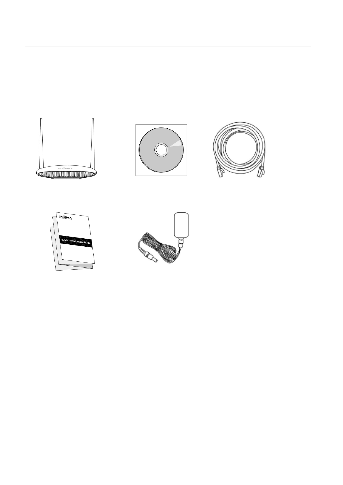
I. Product Information
BR-6478AC V2
Ethernet Cable
Quick Installation Guide
Power Adapter
CD-ROM
I-1. Package Contents
Before you start using this product, please check if there is anything missing in
the package, and contact your dealer to claim the missing item(s):
1
Page 6

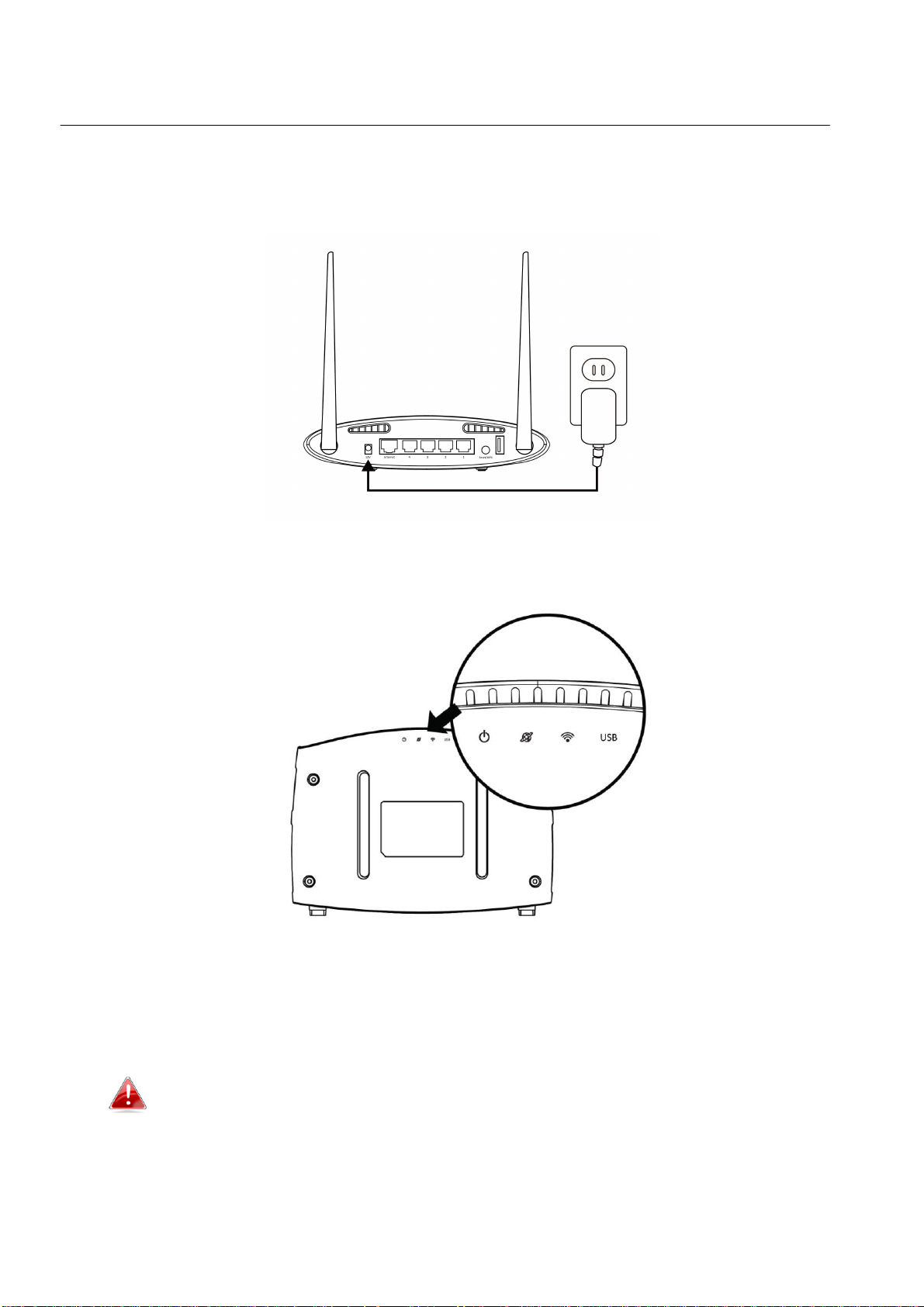
I-2. LED Status
LED
Color
Status
Description
Power
White
On
The device is on.
Off
The device is off.
Internet
Blue
On
Internet connection is ready.
Flashing
Restoring to factory default state,
or Ethernet cable not connected,
or no Internet connection.
Wi-Fi
Blue
On
2.4G and/or 5G Wi-Fi wireless
activity (transferring/receiving
data).
Flashing
WPS is active.
Off
Wi-Fi not active.
USB
Blue
On
USB connection is ready.
Off
USB is not active.
2
Page 7
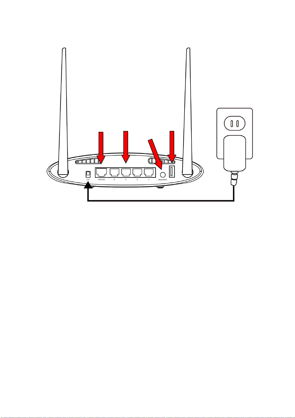
I-3. Back Panel
Internet/
WAN Port
LAN Ports
1 -4
Reset/WPS
Button
USB Port
3
Page 8

I-4. Safety Information
In order to ensure the safe operation of the device and its users, please read
and act in accordance with the following safety instructions.
1. The device is designed for indoor use only; do not place it outdoors.
2. Do not place the device in or near hot/humid places, such as a kitchen or
bathroom.
3. Do not pull any connected cable with force; carefully disconnect it from the
BR-6478 AC V2.
4. Handle the device with care. Accidental damage will void the warranty of
the device.
5. The device contains small parts which are a danger to small children under
3 years old. Please keep the device out of reach of children.
6. Do not place the device on paper, cloth, or other flammable materials. The
device may become hot during use.
7. There are no user-serviceable parts inside the device. If you experience
problems with the device, please contact your dealer of purchase and ask
for help.
8. The device is an electrical device and as such, if it becomes wet for any
reason, do not attempt to touch it without switching the power supply off.
Contact an experienced electrical technician for further help.
4
Page 9
II. Installation
1. Plug the included power adapter into the device’s 12V DC power port and
the other end into an electrical socket.
2. Check that the power LED displays on.
3. Use a Wi-Fi device (e.g. computer, tablet, smartphone) to search for a Wi-Fi
network with the SSID “edimax.setup” or “edimax.setup5G” and connect to
it.
iOS 4 or Android 4 and above are required for setup on a
smartphone or tablet.
5
Page 10
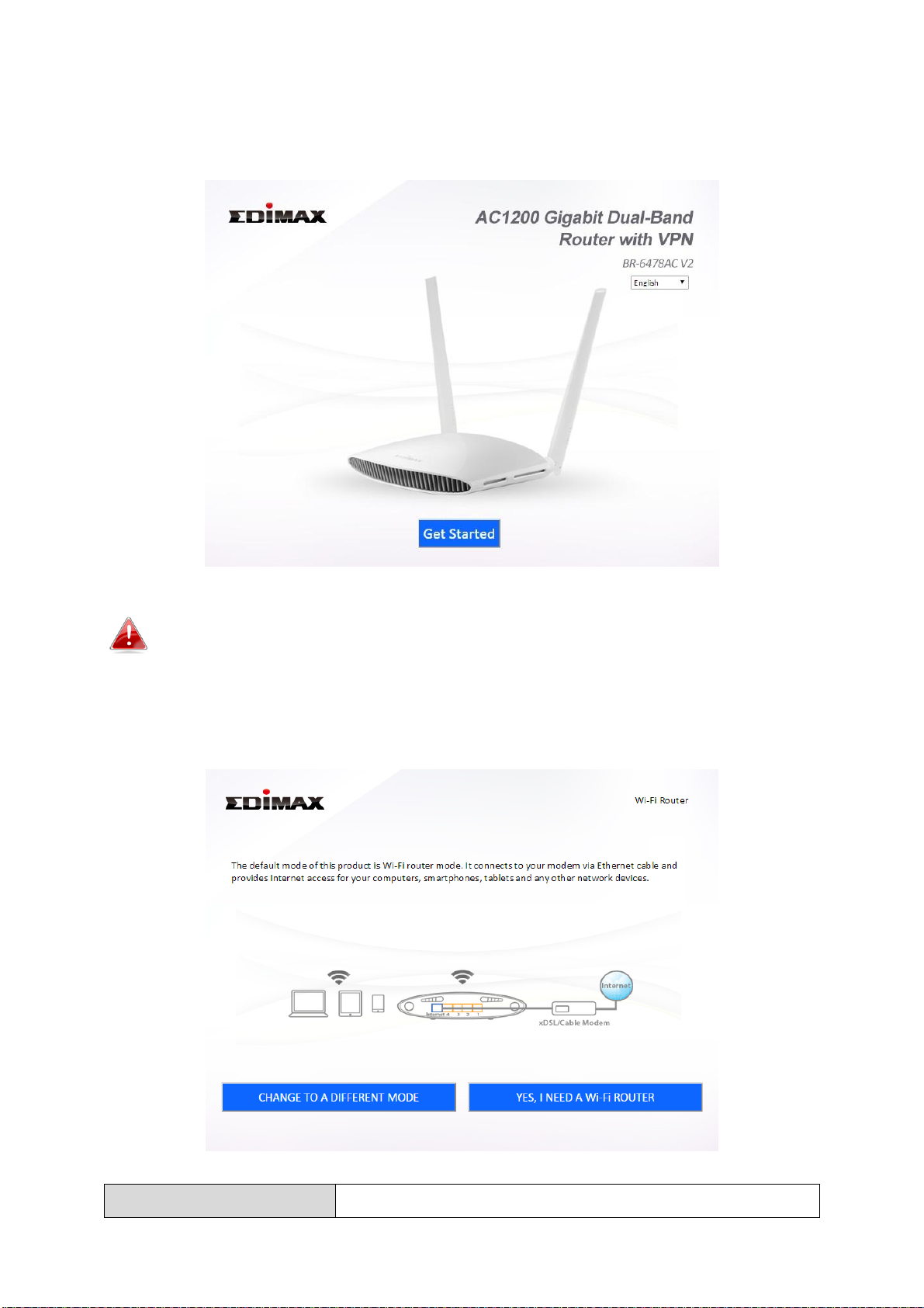
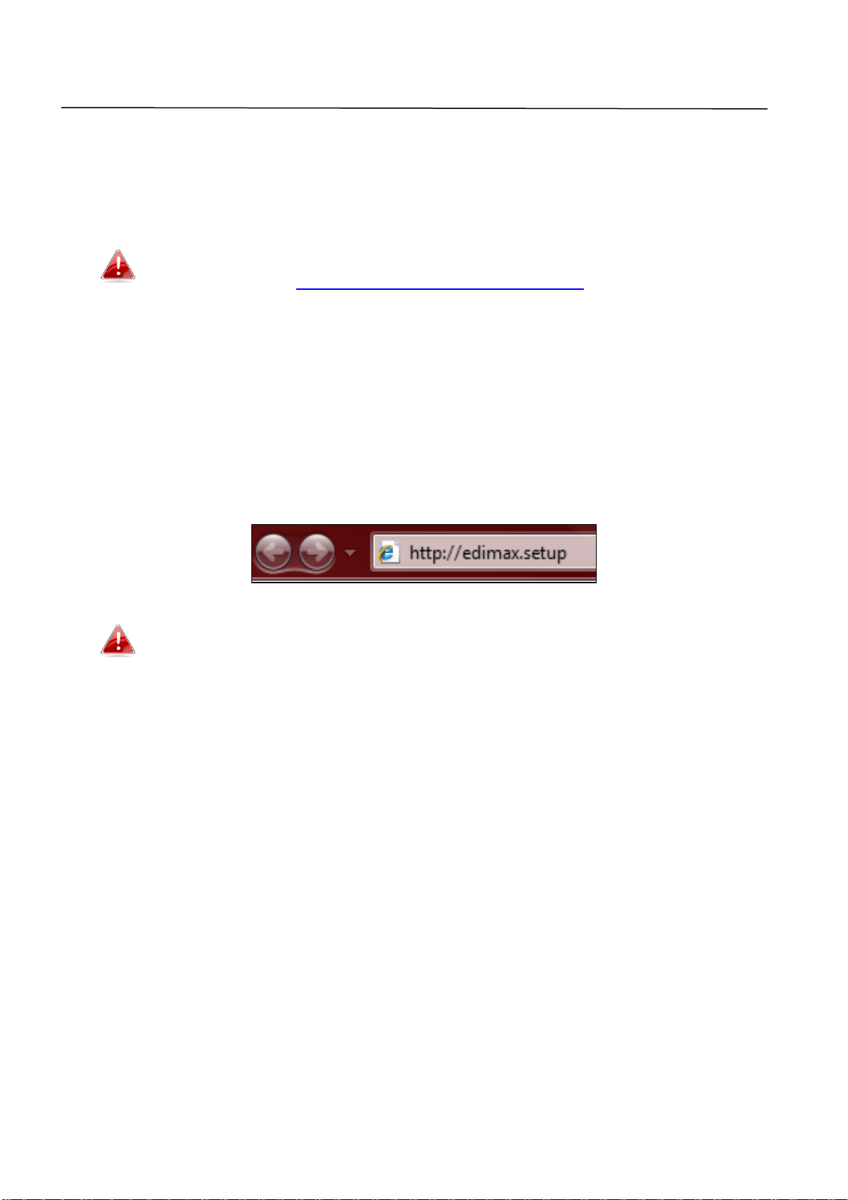
4. Open a web browser and if you do not automatically arrive at the “Get
Wi-Fi Router Mode
The device connects to your modem and provides
Started” screen shown below, enter the URL http://edimax.setup and click
“Get Started” to begin the setup process.
If you cannot access http://edimax.setup, please make sure your
computer is set to use a dynamic IP address.
5. Choose if you want to use your BR-6478AC V2 in its default Wi-Fi router
mode or in a different mode.
6
Page 11

2.4GHz and/or 5GHz Internet (wireless and
Ethernet) access for your network devices.
Access Point Mode
The device connects to an existing router via
Ethernet cable and provides 2.4GHz and/or 5GHz
Internet (wireless and Ethernet) access for your
network devices.
Wi-Fi Extender Mode
The device connects wirelessly to your existing
2.4GHz and/or 5GHz network and repeats the
wireless signal(s).
Wi-Fi Bridge Mode
The device connects to a network device for
example: TV, gaming console, or media player via
Ethernet cable and acts as a Wi-Fi bridge,
allowing the network device to join your Wi-Fi
network.
WISP Mode
The device connects wirelessly to your Wireless
Internet Service Provider and provides 2.4GHz
and/or 5GHz Internet (wireless and Ethernet)
access for your network devices.
6. Follow the on-screen instructions to complete setup. Refer to the following
chapters if you need more help.
7
Page 12
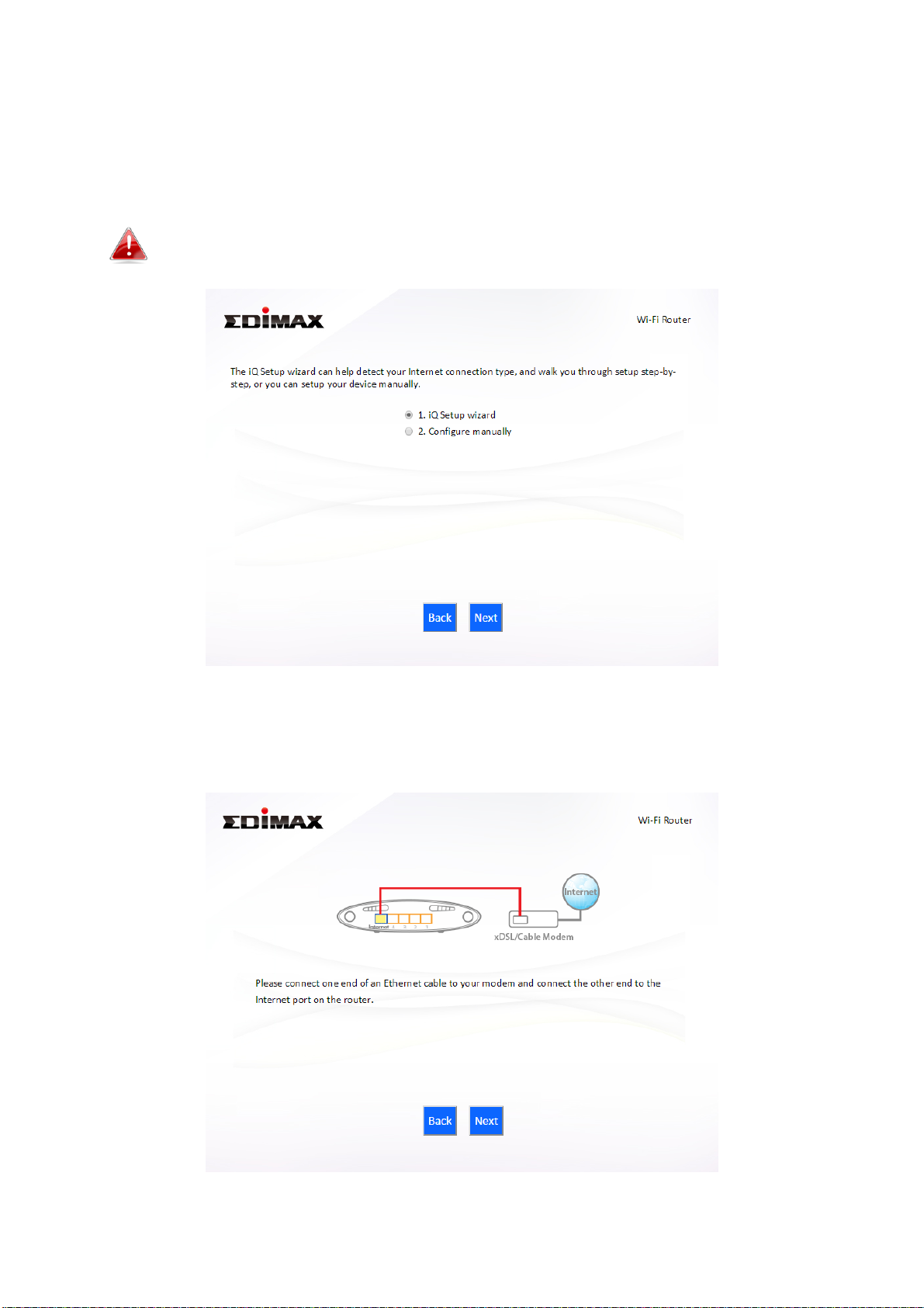
II-1. Wi-Fi Router Mode
1. Select whether to use the iQ Setup wizard (recommended) to detect your
Internet connection type, or enter the settings manually.
Manual configuration is only recommended for advanced users.
2. Connect the blue Internet port of your device to the LAN port of your
modem using an Ethernet cable, and then click “Next”.
8
Page 13

3. Please wait a moment while the device tests the connection.
4. Click “Next” to continue and configure the device’s wireless network.
5. Enter a name and password for your 2.4GHz & 5GHz wireless networks,
then click “Next” to continue.
9
Page 14
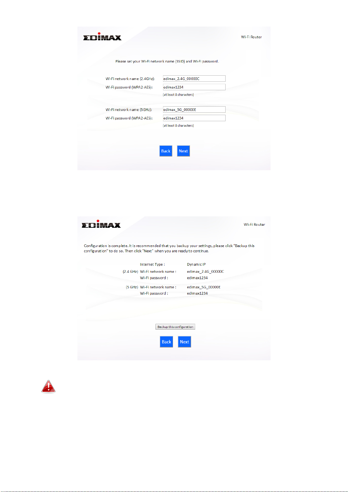
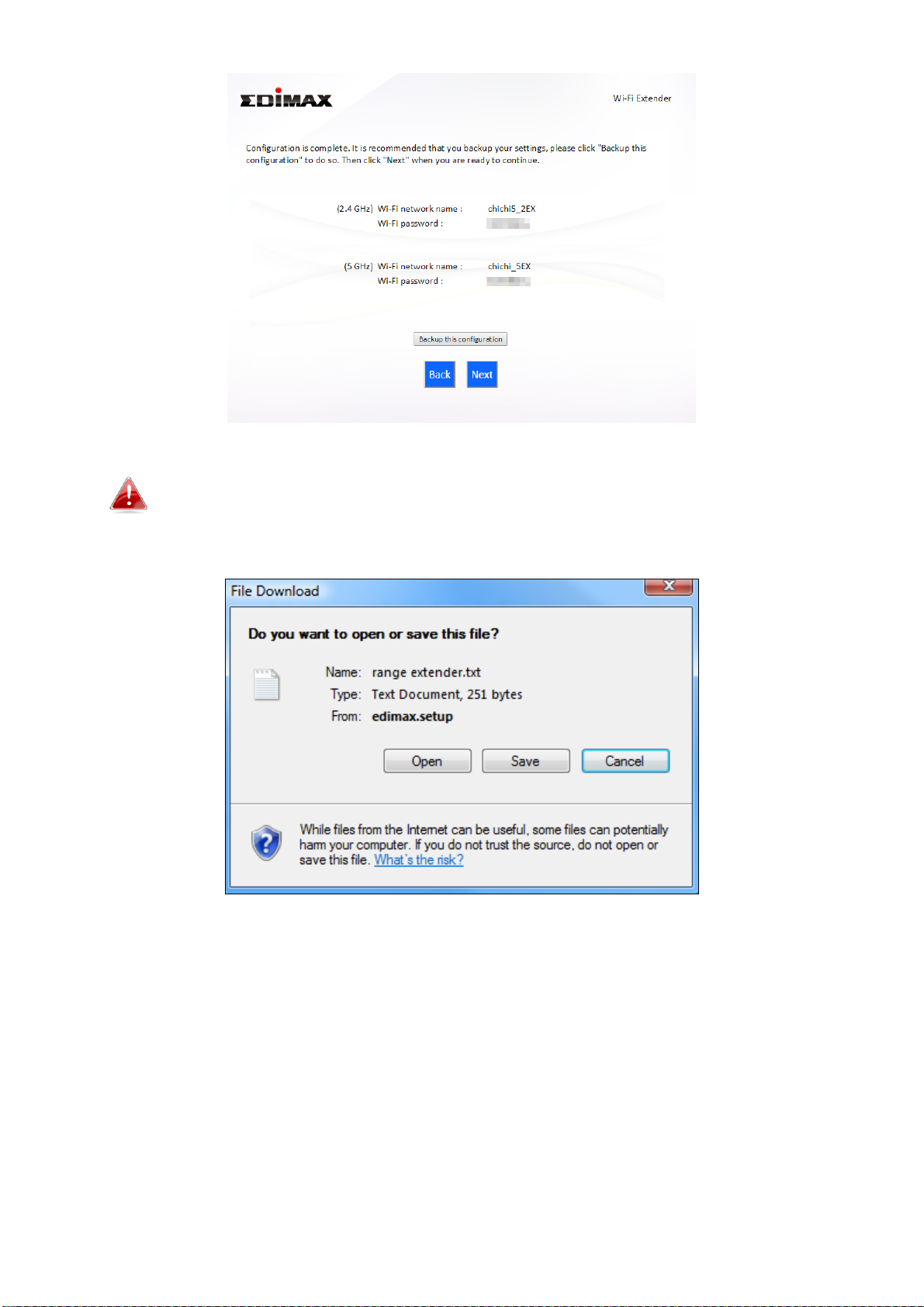
6. A summary of your configuration will be displayed, as shown below.
Check that all of the details are correct and then click “Next” to proceed.
If you wish to backup the device’s settings, click “Backup this
configuration” to open a new window and save your current
configuration to a .txt file.
10
Page 15
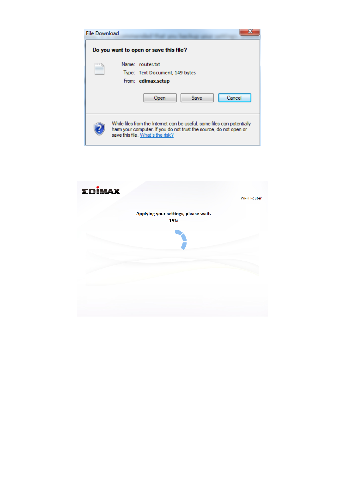
7. Please wait while the device applies your settings.
8. A final congratulations screen will indicate that setup is complete. You can
now connect to the device’s new SSID(s) which are shown on the screen
then close the browser window.
11
Page 16

9. The BR-6478AC V2 is working and ready for use. Refer to IV-2. Connecting
to a Wi-Fi network if you require more guidance.
12
Page 17
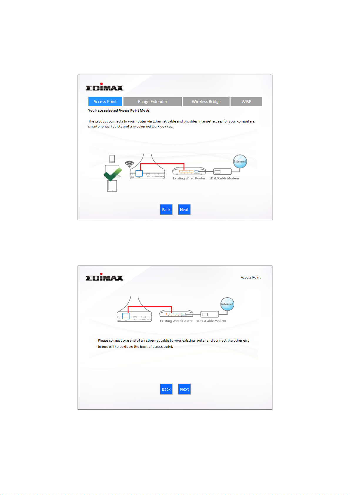
II-2. Access Point Mode
1. Select “Access Point” from the top menu and click “Next”.
2. Connect the network port of your BR-6478 AC V2 to the LAN port of your
existing router using an Ethernet cable, then click “Next”.
3. Select whether to use the 5GHz wireless frequency, 2.4GHz wireless
frequency or both. If you are not sure, select both.
13
Page 18
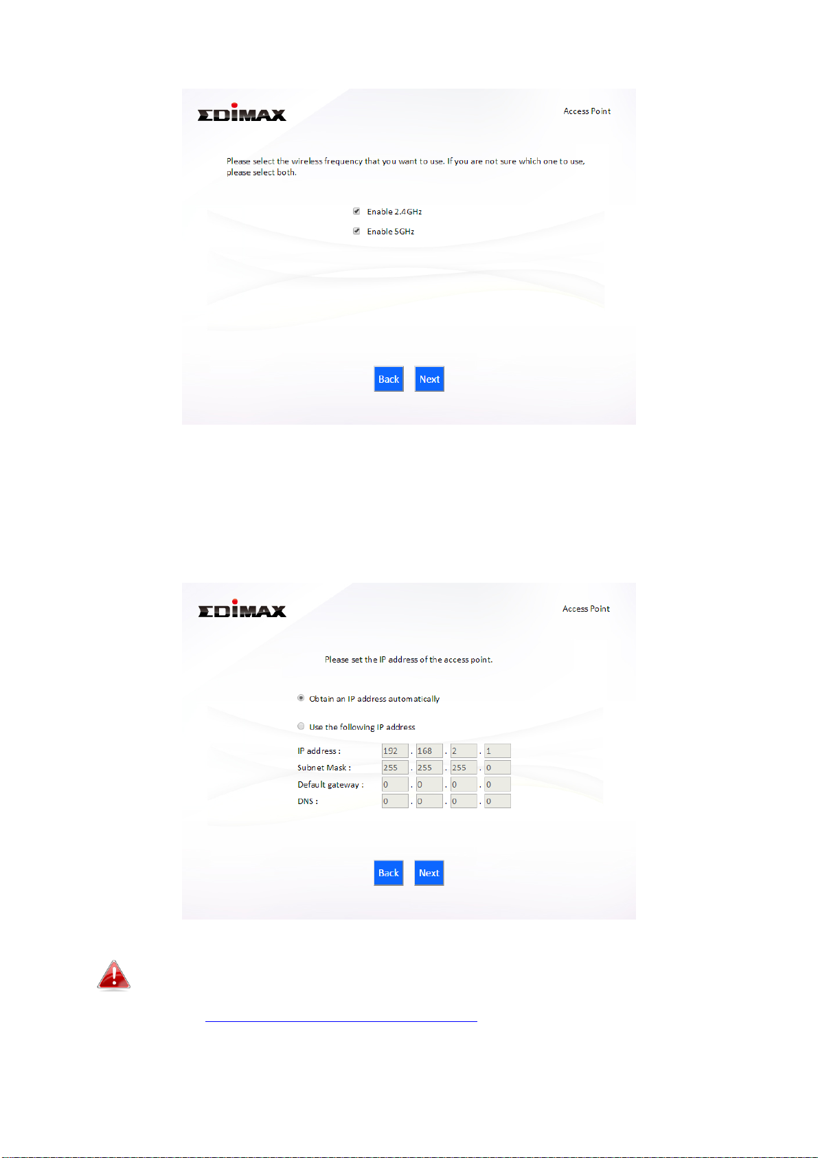
4. Select “Obtain an IP address automatically” or “Use the following IP
address” for your BR-6478 AC V2. If you are using a static IP, enter the IP
address, subnet mask and default gateway. Click “Next” to proceed to the
next step.
“Obtain an IP address automatically” is the recommended setting
for most users. For more guidance on static IP addresses, please
refer to IV-1. Configuring your IP address.
14
Page 19
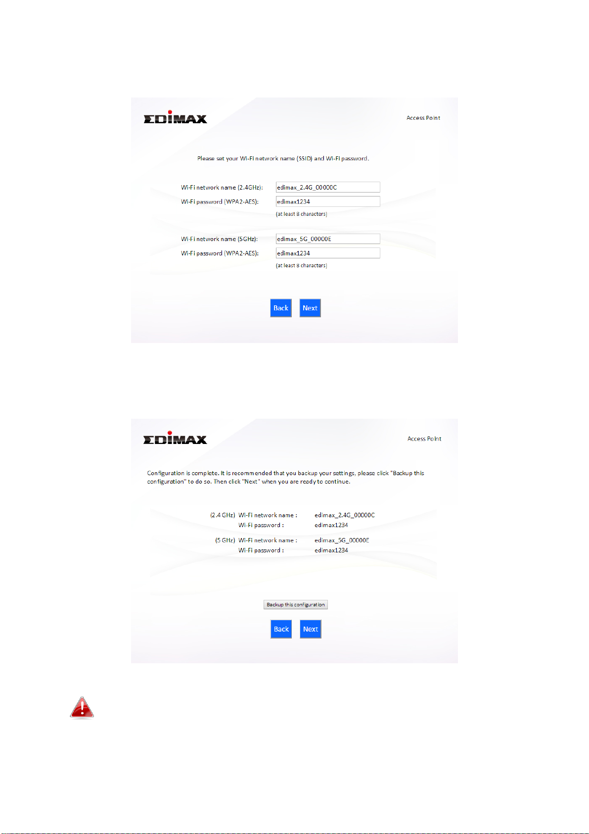
5. Enter a name and password for your 2.4GHz & 5GHz wireless networks,
then click “Next” to continue.
6. A summary of your configuration will be displayed, as shown below.
Check that all of the details are correct and then click “Next” to proceed.
If you wish to backup the device’s settings, click “Backup this
configuration” to open a new window and save your current
configuration to a .txt file.
15
Page 20
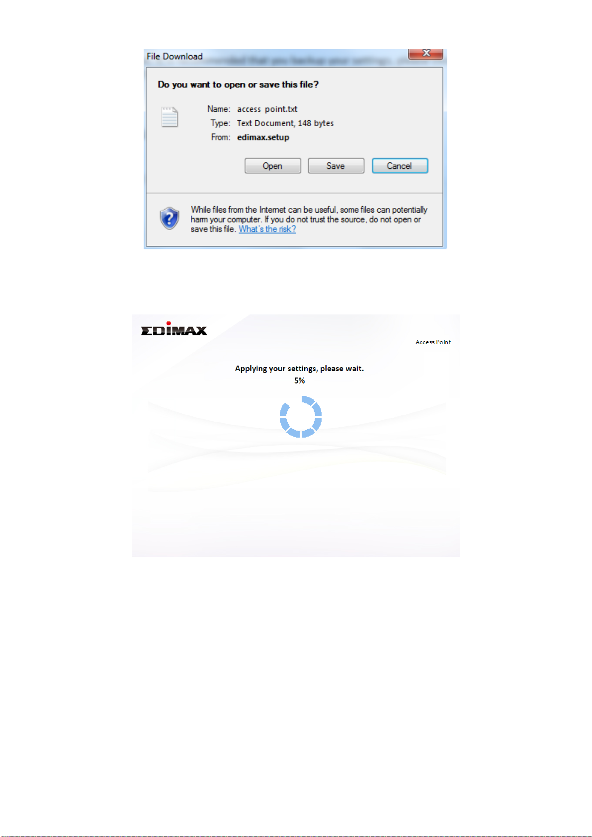
7. Please wait a moment until the BR-6478 AC V2 is ready.
8. A final congratulations screen will indicate that setup is complete. You can
now connect to the device’s new SSID(s) which are shown on the screen
then close the browser window.
16
Page 21

9. The BR-6478 AC V2 is working and ready for use. Refer to IV-2.
Connecting to a Wi-Fi network if you require more guidance.
17
Page 22
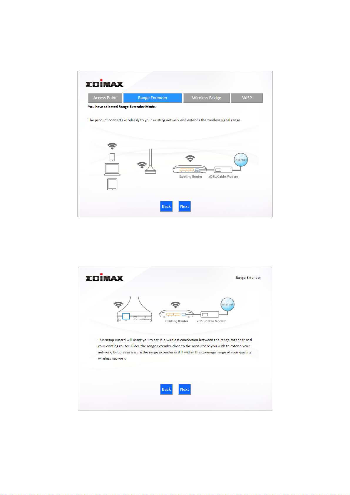
II-3. Range Extender Mode
1. Select “Range Extender” from the top menu and click “Next”.
2. Please ensure your BR-6478 AC V2 is within Wi-Fi range of your existing
wireless router. Click “Next” to continue.
3. Select whether to use the 5GHz wireless frequency, 2.4GHz wireless
frequency or both. If you are not sure, select both and then click “Next”.
18
Page 23
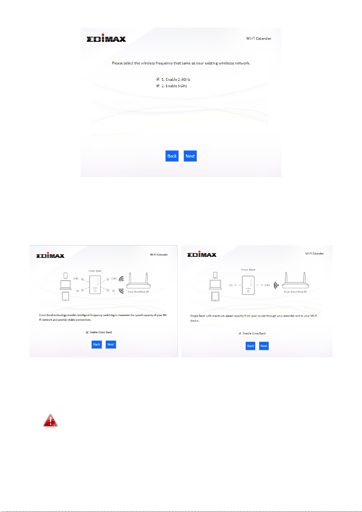
4. Select whether to enable Cross Band technology. This can help to
maintain your router’s maximum speed capacity as the Wi-Fi signal is
extended.
5. Select the Wi-Fi network name (SSID) which you wish to connect to for
the specified frequency and click “Next” to continue.
If the Wi-Fi network you wish to connect to does not appear, try
clicking “Refresh”.
19
Page 24
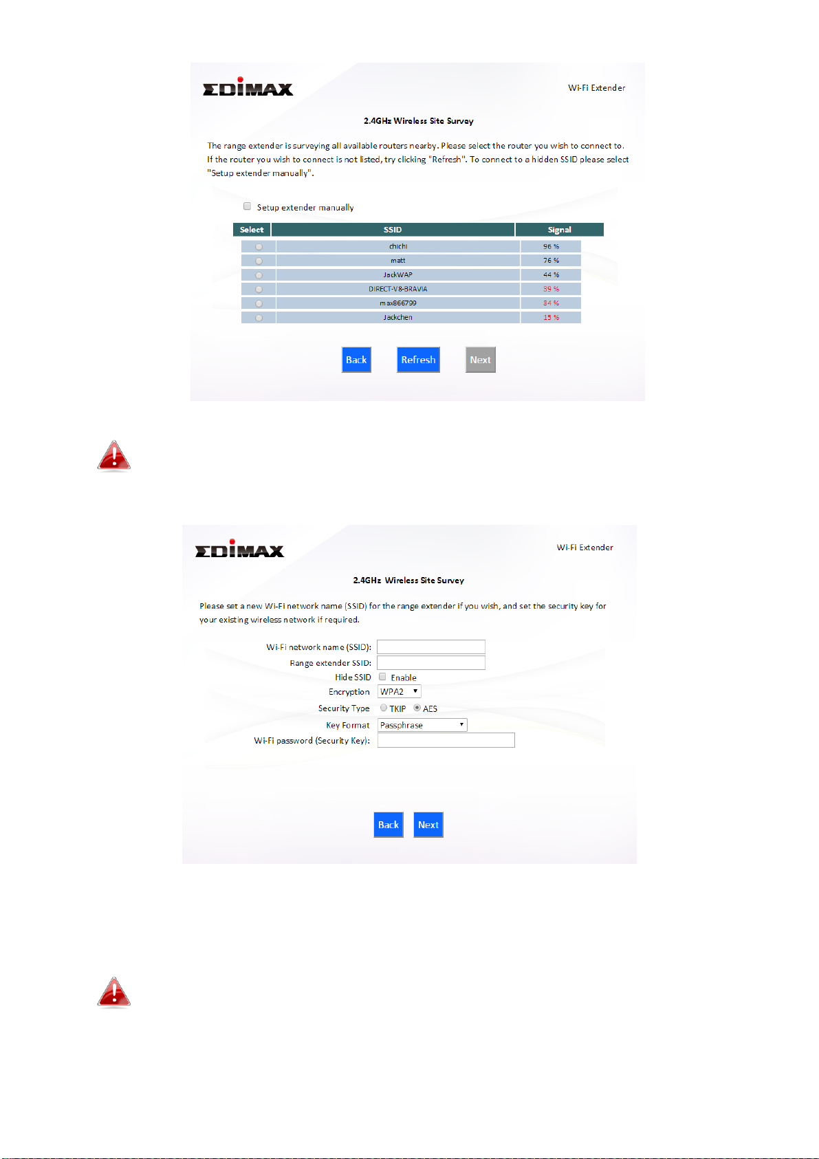
To connect to a hidden SSID, check the “Setup extender manually”
box and enter the details manually on the next page, as shown
below.
6. Enter your existing wireless network’s security key/password in the
“Security Key” field and click “Next” to continue.
Device SSID will be the SSID of your extender’s Wi-Fi. If using
cross-band technology this will be 5GHz Wi-Fi for your router’s
2.4GHz signal and vice versa.
20
Page 25
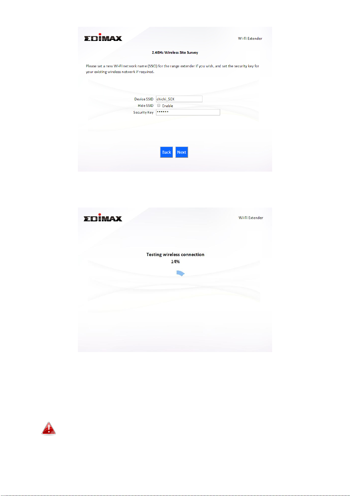
7. Wait a moment while the BR-6478 AC V2 tests the wireless connection.
8. Select “Obtain an IP address automatically” or “Use the following IP
address” for your BR-6478 AC V2. If you are using a static IP, enter the IP
address, subnet mask and default gateway. Click “Next” to proceed to
the next step.
“Obtain an IP address automatically” is the recommended setting
for most users. The IP address will be displayed in brackets.
21
Page 26
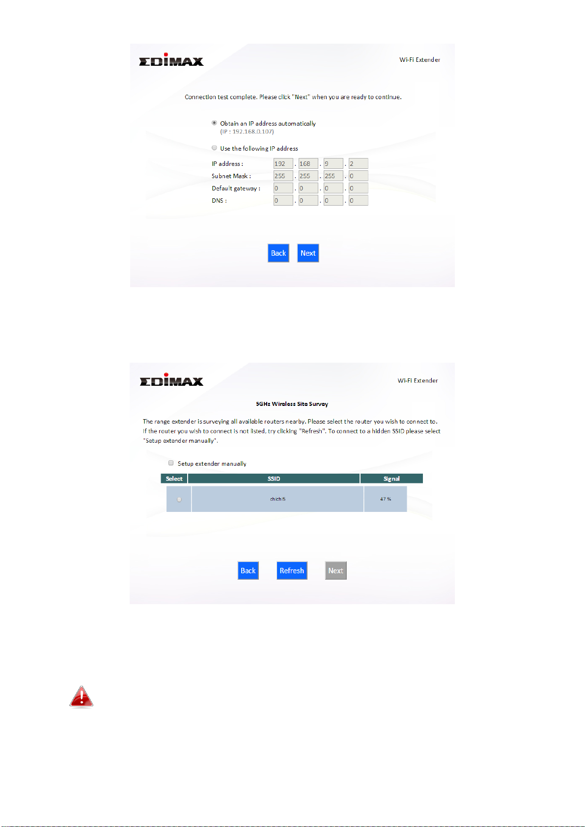
9. If you selected to use both 2.4GHz and 5GHz wireless frequencies in
step 3, then repeat steps 4 – 7 for the 2.4GHz wireless frequency.
10. A summary of your configuration will be displayed, as shown below.
Check that all of the details are correct and then click “Next” to proceed.
The device will use the same wireless password/security key as
the existing wireless network.
22
Page 27
If you wish to backup the BR-6478 AC V2’s settings, click “Backup
this configuration” to open a new window and save your current
configuration to a .txt file.
11. Please wait a moment until the BR-6478 AC V2 is ready.
23
Page 28

12. A final congratulations screen will indicate that setup is complete. You
can now connect to the device’s new SSID(s) which are shown on the
screen then close the browser window.
24
Page 29

13. The BR-6478 AC V2 is working and ready for use. Refer to IV-2.
Connecting to a Wi-Fi network if you require more guidance.
25
Page 30
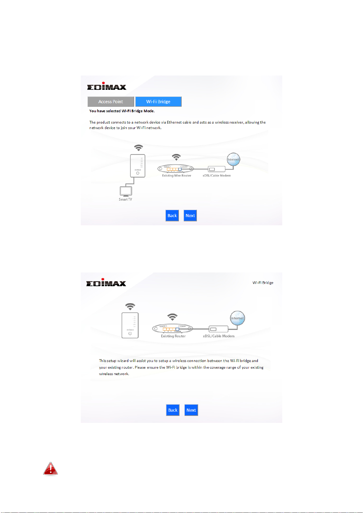
II-4. Wireless Bridge Mode
1. Select “Wireless Bridge” from the top menu and click “Next”.
2. Please ensure your BR-6478 AC V2 is within Wi-Fi range of your existing
wireless router. Click “Next” to continue.
3. Select the frequency (2.4GHz or 5GHz) of your existing wireless network.
In wireless client mode, the BR-6478 AC V2 can only connect to
one wireless network/frequency i.e. 2.4GHz or 5GHz.
26
Page 31

4. Select the Wi-Fi network name (SSID) which you wish to connect to and
click “Next” to continue.
If the Wi-Fi network you wish to connect to does not appear, try
clicking “Refresh”.
To connect to a hidden SSID, check the “Setup extender manually”
box and enter the details manually on the next page, as shown
below.
27
Page 32

5. Enter your existing wireless network’s security key/password in the
“Security Key” field and click “Next” to continue.
6. Wait a moment while the BR-6478 AC V2 tests the wireless connection.
7. Select “Obtain an IP address automatically” or “Use the following IP
address” for your BR-6478 AC V2. If you are using a static IP, enter the IP
address, subnet mask and default gateway. Click “Next” to proceed to the
next step.
28
Page 33

“Obtain an IP address automatically” is the recommended setting
for most users. The IP address will be displayed in brackets.
8. A summary of your configuration will be displayed, as shown below.
Check that all of the details are correct and then click “Next” to proceed.
If you wish to backup the BR-6478 AC V2’s settings, click “Backup
this configuration” to open a new window and save your current
configuration to a .txt file.
29
Page 34

9. Please wait a moment until the BR-6478 AC V2 is ready.
10. A final congratulations screen will indicate that setup is complete.
Please close the browser window.
30
Page 35

11. The BR-6478 AC V2 is working and ready for use. You can now
connect the BR-6478 AC V2 to your network device using an Ethernet cable
and connect to your network as usual.
31
Page 36
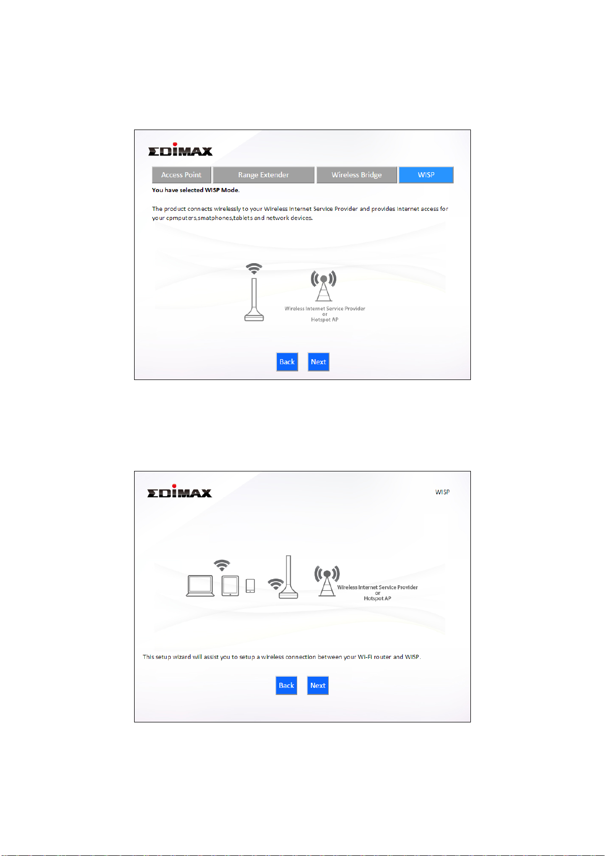
II-5. WISP Mode
1. Select “WISP” from the top menu and click “Next”.
2. Please ensure your BR-6478 AC V2 is within Wi-Fi range of your WISP
network and click “Next” to continue.
3. Select whether to use the iQ Setup wizard (recommended) to detect your
Internet connection type, or enter the settings manually.
32
Page 37

Manual configuration is only recommended for advanced users.
4. Select the wireless frequency (2.4GHz or 5GHz) of your WISP network.
5. Select the WISP SSID which you wish to connect to and click “Next” to
continue.
If the Wi-Fi network you wish to connect to does not appear, try
clicking “Refresh”.
33
Page 38

To connect to a hidden SSID, check the “Setup extender manually”
box and enter the details manually on the next page, as shown
below.
6. Enter your existing wireless network’s security key/password in the
“Security Key” field and click “Next” to continue.
34
Page 39

7. Wait a moment while the BR-6478 AC V2 tests the wireless connection.
8. Click “Next” to continue your Internet service type configuration.
35
Page 40

9. Wait a moment while the BR-6478 AC V2 connects to the Internet.
10. When the Internet is connected, click “Next” to configure your
wireless network.
36
Page 41

11. Enter a name and password for your 2.4GHz & 5GHz wireless networks,
then click “Next” to continue.
12. A summary of your configuration will be displayed, as shown below.
Check that all of the details are correct and then click “Next” to proceed.
37
Page 42

If you wish to backup the device’s settings, click “Backup this
configuration” to open a new window and save your current
configuration to a .txt file.
13. Please wait a moment until the BR-6478 AC V2 is ready.
38
Page 43

14. A final congratulations screen will indicate that setup is complete. You
can now connect to the device’s new SSID(s) which are shown on the
screen then close the browser window.
15. The BR-6478 AC V2 is working and ready for use. Refer to IV-2.
Connecting to a Wi-Fi network if you require more guidance.
39
Page 44

II-6. WPS Setup
If your wireless device supports WPS (Wi-Fi Protected Setup) then you can use this
method to connect to the BR-6478 AC V2’s Wi-Fi network.
1. Press the WPS/Reset button on the BR-6478 AC V2 for 2 seconds to activate
WPS. The LED will then flash blue to indicate that WPS is active.
2. Within two minutes, press the WPS button on the wireless device/client to
activate its WPS.
3. The devices will establish a connection. Repeat for additional wireless devices.
Please check the instructions for your wireless device for how long
you need to hold down its WPS button to activate WPS.
II-7. Reset to Factory Default Settings
If you experience problems with your BR-6478 AC V2, you can reset the device
back to its factory settings. This resets all settings back to default.
1. Press and hold the WPS/Reset button found on the rear base of the
product for at least 10 seconds.
2. Release the button when the LED is flashing blue.
3. Wait for the BR-6478 AC V2 to restart.
40
Page 45
III. Browser Based Configuration Interface
After you have setup the BR-6478 AC V2 as detailed in II. Installation or the
included Quick Installation Guide, you can use the browser based
configuration interface to configure advanced settings.
Please ensure that your computer is set to use a dynamic IP
address. Refer to IV-1. Configuring your IP address for more
information.
III-1. Login
1. To access the browser based configuration interface enter
http://edimax.setup into the URL bar of a browser on a network device
connected to the same Wi-Fi network as the BR-6478 AC V2.
If you can not access http://edimax.setup, connect the device to a
computer using an Ethernet cable and try again.
2. You will be prompted for a username and password. The default
username is “admin” and the default password is “1234”.
41
Page 46

3. You will arrive at the “Status” screen. Use the menu down the left side to
navigate.
42
Page 47
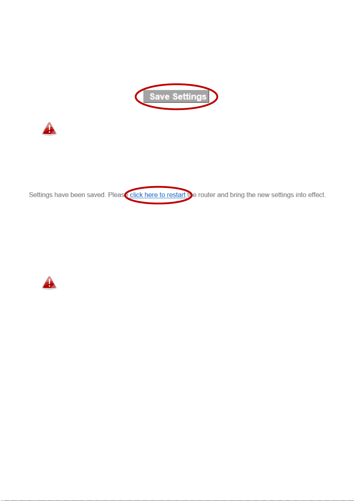
III-2. Save Settings
1. After you configure any settings, click the “Save Settings” button at the
bottom of the screen to save your changes.
The device needs to restart in order to bring any changes into
effect.
2. Then, click “Click here to restart” in order to restart the device and bring
the changes into effect.
3. To make several changes at once, use the “Save Settings” button after
each change and then click “click here to restart” after your final change.
Only one restart is necessary as long as each change is saved with the “Save
Settings” button.
After you click “click here to restart”, all saved changes will come
into effect.
43
Page 48

III-3. Main Menu
Wi-Fi Router
Access Point
Range Extender
Wireless Bridge
WISP
The main menu displays different options depending on your device’s
operating mode.
For Range Extender mode: WPS please refer to 2.4GHz Wireless &
5GHz Wireless WPS
44
Page 49

III-3-1. Status
Screenshots displayed are examples.The information shown on
your screen will vary depending on your configuration.
The “Status” page displays basic system information
about the device, arranged into categories.
You can click the orange Check the latest version button to open a new
screen and automatically upgrade firmware to the latest version. Click
Firmware auto-upgrade to begin the process.
It is recommended to backup the existing firmware version using
the “Save as File” button before upgrading.
45
Page 50

III-3-2. Setup Wizard
Setup Wizard
This wizard will help you to set up the basic
functions and settings of the device. For
guidance about using the setup wizard, please
refer to II. Installation.
Switch to Router/Access
Point/ Range Extender/
Wireless Bridge/ WISP
mode
This wizard will help you to switch the device
to a different operating mode: Wi-Fi router
mode, access point mode, range extender,
wireless bridge, or WISP mode (see below).
You can run the setup wizard again to reconfigure the
basic settings of the device, or you can run a wizard to
help you switch the device to a different operating mode. Select “Setup
Wizard” or “Switch to Router/Access Point/Range Extender/Wireless
Bridge/WISP mode” and then click “Run Wizard” to begin.
Switch to Router/Access Point/ Range Extender/ Wireless Bridge/ WISP
mode:
1. Follow the on-screen instructions to back up your current settings and
then reset the device back to its factory default settings.
2. After the device has reset you will see the screen below. Close your
browser and open it again.
46
Page 51

3. Follow the on-screen wizard to setup your device in a different mode.
Refer to II. Installation Step 3 onwards for help if needed.
If you don’t see the “Get Started” screen, try reconnecting to the
edimax.setup SSID and go to http://edimax.setup in a web
browser.
47
Page 52
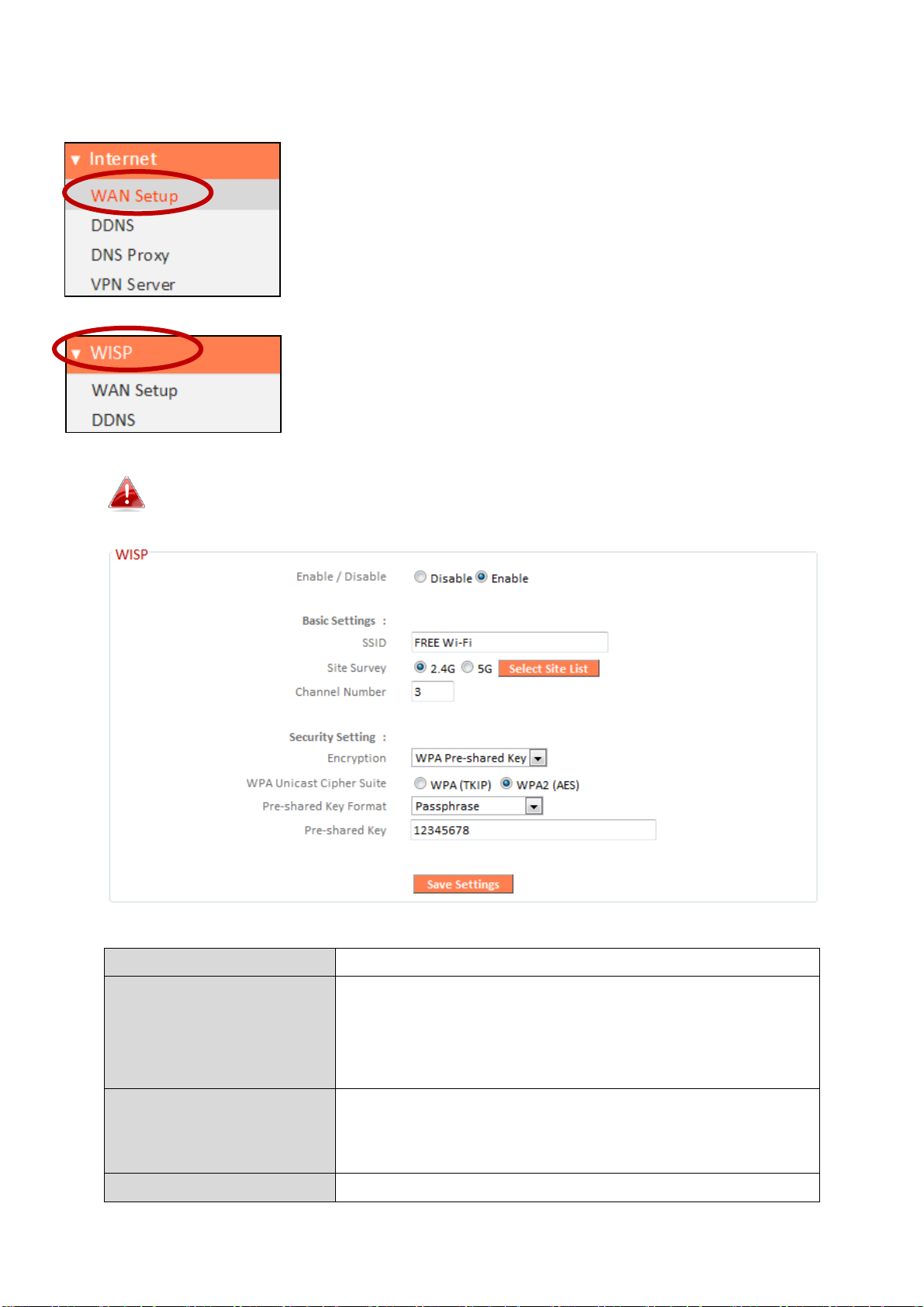
III-3-3. Internet/WISP
Enable / Disable
Enable or disable your WISP connection.
SSID
The name of the WISP network which your
BR-6478 AC V2 is connected to. Manually
enter an SSID if you wish or use “Site Survey”
below.
Site Survey
Select wireless frequency and click “Select
Site List” to open a new window and select
your WISP network.
Security Setting
Please refer to III-3-5-1. Basic for a
The “Internet” menu provides access to WAN, DDNS,
DNS Proxy & VPN server settings. Click on an item from
the submenu to view and/or configure the settings.
In WISP mode, the screen below will be displayed:
48
Page 53

description of security settings.
49
Page 54

III-3-3-1. WAN Setup
Select a Wide Area Network (WAN) connection mode and configure the
settings. If you are unsure about your connection type, contact your ISP.
In WISP mode, only Dynamic IP, Static IP & PPPoE are available for
WAN Connection Mode.
III-3-3-1-1. Dynamic IP
Select “Dynamic IP”. If your Internet service provider assigns IP address
automatically using DHCP (Dynamic Host Configuration Protocol).
50
Page 55

Host Name
Enter the host name of your computer.
MAC Address
For some applications, you may need to
designate a specific MAC address for the
router. Please enter the MAC address here. If
you are connecting the router to a computer,
press “Clone Mac” to automatically enter
your computer’s MAC address.
DNS Address
Select “Obtain an IP address automatically” or
“Use the following IP address”. Check with
your ISP if you are unsure.
DNS Address 1,2 & 3
Enter the DNS address(es) assigned by your
ISP here.
MTU
Enter the maximum transmission unit (MTU)
value of your network connection. The
default value is 1500.
TTL
Enable/Disable time to live (TTL) function
which limits the lifespan of network data to
improve performance.
51
Page 56

III-3-3-1-2. Static IP
Fixed IP Address
Input the IP address assigned by your ISP
here.
Subnet Mask
Input the subnet mask assigned by your ISP
here.
Default Gateway
Address
Input the default gateway assigned by your
ISP here. Some ISPs may call this “Default
Route”.
MAC Address
For some applications, you may need to
designate a specific MAC address for the
router. Please enter the MAC address here. If
you are connecting the router to a computer,
press “Clone Mac” to automatically enter
your computer’s MAC address.
DNS Address 1, 2 &
3
Enter the DNS address(es) assigned by your
ISP here.
DNS Proxy
Enable or disable a DNS proxy server.
DNS Proxy Rules
When DNS proxy is enabled, enter the URL of
Select “Static IP” if your ISP provides Internet access via a fixed IP address.
Your ISP will provide you with such information as IP address, subnet mask,
gateway address, and DNS address.
52
Page 57

(URL)
a DNS proxy server.
TTL
Enable/Disable time to live (TTL) function
which limits the lifespan of network data to
improve performance.
53
Page 58

III-3-3-1-3. PPPoE
User Name
Enter the user name assigned by your ISP
here.
Password
Enter the password assigned by your ISP here.
MAC Address
For some applications, you may need to
designate a specific MAC address for the
router. Please enter the MAC address here. If
you are connecting the router to a computer,
press “Clone Mac” to automatically enter
Select “PPPoE” if your ISP is providing you Internet access via PPPoE
(Point-to-Point Protocol over Ethernet).
54
Page 59

your computer’s MAC address.
DNS Address
Select “Obtain an IP address automatically” or
“Use the following IP address”. Check with
your ISP if you are unsure.
DNS Address 1, 2 &
3
Enter the DNS address(es) assigned by your
ISP here.
TTL
Enable or disable TTL.
Service Name
Give this Internet service a name (optional).
MTU
Enter the maximum transmission unit (MTU)
value of your network connection. The
default value is 1392.
Connection Type
Specify a connection type:
1. “Continuous”: Connected all the time.
2. “Connect on Demand”: Connect when you
initiate an Internet connection.
3. “Manual”: Connect/disconnect manually
using the “Connect” and “Disconnect”
buttons.
Idle Time Out
Specify the amount of time the router waits
before shutting down an idle connection.
Only available when “Connect on Demand”
(above) is selected.
Enable Dual-WAN
Access
Enable/disable dual WAN access. When you
enable dual WAN access, select an IGMP
source and enter a “Host Name” and “MAC
Address”.
55
Page 60

III-3-3-1-4. PPTP
Select “PPTP” if your ISP is providing you Internet access via PPTP
(Point-to-Point Tunneling Protocol). Then select “Obtain an IP address
automatically” or “Use the following IP address” depending on your ISP.
56
Page 61

Host Name
Enter the host name of your computer here If
required.
MAC Address
For some applications, you may need to designate a
specific MAC address for the router. Please enter
the MAC address here. If you are connecting the
router to a computer, press “Clone Mac” to
automatically enter your computer’s MAC address.
Static IP Address
Input the IP address assigned by your ISP here.
Subnet Mask
Input the subnet mask assigned by your ISP here.
Default Gateway
Address
Input the default gateway assigned by your ISP
here. Some ISPs may call this “Default Route”.
MAC Address
If your ISP filters access by MAC addresses, enter
your computer’s MAC address here. Click “Clone
MAC” to automatically enter your computer’s MAC
address.
DNS Address
Select “Obtain an IP address automatically” or “Use
the following IP address”. Check with your ISP if you
are unsure.
DNS Address 1,2 & 3
Enter the DNS address(es) assigned by your ISP
here.
DNS Proxy
Enable or disable a DNS proxy server.
DNS Proxy Rules
(URL)
When DNS proxy is enabled, enter the URL of a DNS
proxy server.
Enable Dual-WAN
Access
Enable/disable dual WAN access. When you enable
dual WAN access, select an IGMP source.
User ID
Input the user name assigned by your ISP here.
Password
Input the password assigned by your ISP here.
PPTP Gateway
Input the PPTP gateway assigned by your ISP here.
Connection ID
Specify a reference name/ID for the connection.
MTU
Enter the maximum transmission unit (MTU) value
of your network connection. The default value is
1392.
BEZEQ-ISRAEL
Check the “Enable” box if you are using BEZEQ
network services (Israel users only).
Connection Type
Specify a connection type:
1. “Continuous”: Connected all the time.
2. “Connect on Demand”: Connect when you
initiate an Internet connection.
3. “Manual”: Connect/disconnect manually using
57
Page 62

the “Connect” and “Disconnect” buttons.
Idle Time Out
Specify the amount of time the router waits before
shutting down an idle connection. Only available
when “Connect on Demand” (above) is selected.
Host Name
Enter the host name of your computer here If
required.
III-3-3-1-5. L2TP
Select “L2TP” if your ISP is providing you Internet access via L2TP (Layer 2
Tunneling Protocol).
58
Page 63

MAC Address
For some applications, you may need to designate a
specific MAC address for the router. Please enter
the MAC address here. If you are connecting the
router to a computer, press “Clone Mac” to
automatically enter your computer’s MAC address.
Static IP Address
Input the IP address assigned by your ISP here.
Subnet Mask
Input the subnet mask assigned by your ISP here.
Default Gateway
Address
Input the default gateway assigned by your ISP
here. Some ISPs may call this “Default Route”.
MAC Address
If your ISP filters access by MAC addresses, enter
your computer’s MAC address here. Click “Clone
MAC” to automatically enter your computer’s MAC
address.
DNS Address
Select “Obtain an IP address automatically” or “Use
the following IP address”. Check with your ISP if you
are unsure.
DNS Address 1,2 & 3
Enter the DNS address(es) assigned by your ISP
here.
Enable Dual-WAN
Access
Enable/disable dual WAN access. When you enable
dual WAN access, select an IGMP source and enter
a “Host Name” and “MAC Address”.
User ID
Input the user name assigned by your ISP here.
Password
Input the password assigned by your ISP here.
L2TP Gateway
Input the L2TP gateway assigned by your ISP here.
Connection ID
Specify a reference name/ID for the connection.
MTU
Enter the maximum transmission unit (MTU) value
of your network connection. The default value is
1392.
Connection Type
Specify a connection type:
1. “Continuous”: Connected all the time.
2. “Connect on Demand”: Connect when you
initiate an Internet connection.
3. “Manual”: Connect/disconnect manually using
the “Connect” and “Disconnect” buttons.
Idle Time Out
Specify the amount of time the router waits before
shutting down an idle connection. Only available
when “Connect on Demand” (above) is selected.
59
Page 64

III-3-3-2. DDNS
Enable/Disable
Enable or disable DDNS
Provider
Select DDNS service provider.
Domain Name
Enter the domain name provided by the
DDNS provider.
Account/Email
Please enter the DDNS registration
account/email.
Password/Key
Enter the DDNS service password/key.
Dynamic DNS (DDNS) is a service which provides a hostname-to-IP service for
dynamic IP users. The changing nature of dynamic IPs means that it can be
difficult to access a service provided by a dynamic IP user; a DDNS service
though can map such dynamic IP addresses to a fixed hostname, for easier
access. The router supports several DDNS service providers, for more details
and to register for a DDNS account please visit the DDNS providers website(s),
examples of which are listed below.
The following DDNS services are supported:
3322 http://www.3322.org
DHS http://www.dhs.org
DynDNS http://www.dyndns.org
ODS http://ods.org
TZO http://www.tzo.com
GnuDIP http://gnudip2.sourceforge.net
DyNS http://www.dyns.cx/
ZoneEdit http://www.zoneedit.com
60
Page 65

DHIS http://www.dhis.org/
CyberGate http://cybergate.planex.co.jp/ddns/
NS2GO http://www.ns2go.com/
NO-IP http://www.noip.com/
61
Page 66
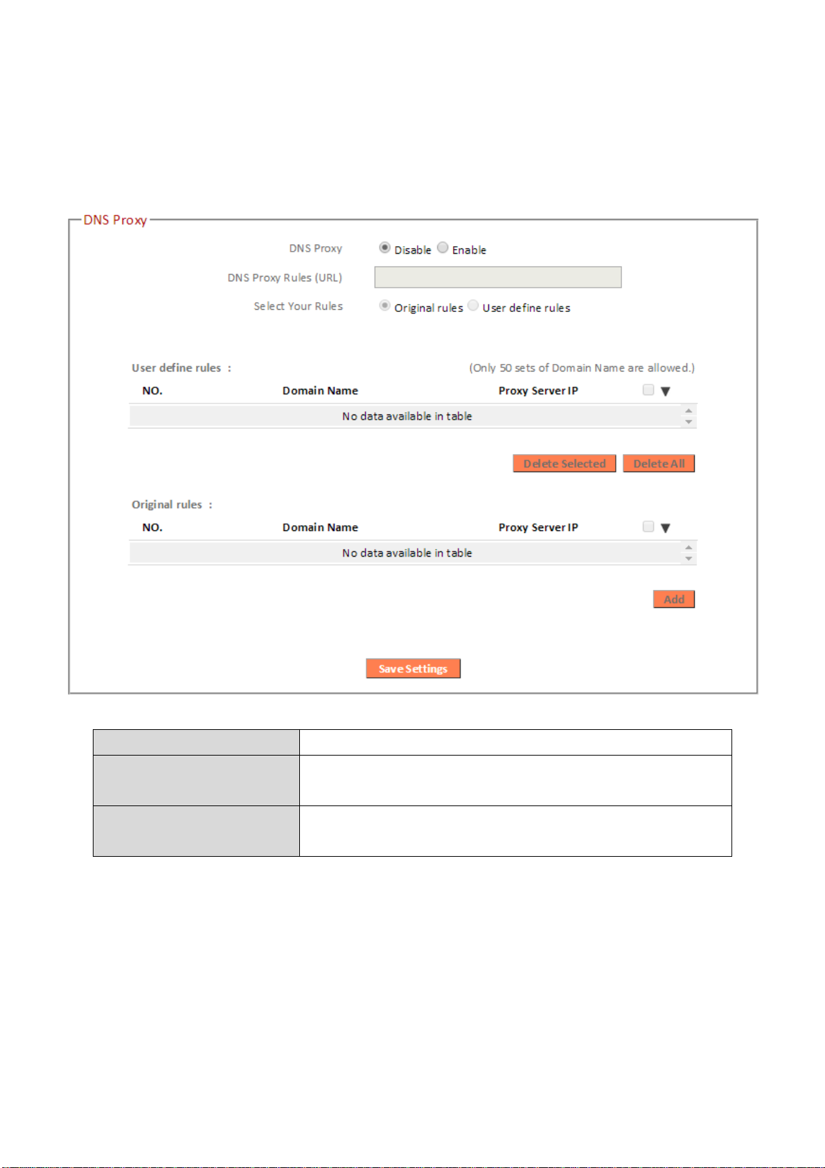
III-3-3-3. DNS Proxy
DNS Proxy
Enable or disable a DNS proxy server.
DNS Proxy Rules
(URL)
When DNS proxy is enabled, enter the URL of
a DNS proxy server.
Select Your Rules
Enter the domain name provided by the
DDNS provider.
DNS Proxy is a DNS service which re-routes traffic to a proxy server in a
different geographical location/region.
62
Page 67

III-3-3-4. VPN Server
A VPN is a virtual private network which you can connect to remotely. VPNs
are secure and encrypted. Your router has a built-in VPN server which you
can configure and access on your network devices, including smartphones,
tablets and computers.
1. Enable VPN server.
2. Export your VPN server configuration file. You can open this file on your
network device (smartphone, tablet, computer) using VPN software/app to
automatically connect to your VPN on your device.
You can choose which kind of configuration file to export,
depending on your requirement. “Send All Traffic Over VPN
63
Page 68

Server” will configure your network device to use the VPN for all
Internet traffic. “Send Only Home Network Traffic over VPN
Server” will configure your network device to access the Internet
as usual but use the VPN to access your home (router) network.
The 2nd option is ideal if you only wish to use the VPN for remote
access to your home network. The 1st option will encrypt all
Internet traffic through the VPN.
3. Setup a login account for your VPN. This is required to access your VPN on
your network device.
4. Send the exported configuration file to your network device (e.g. via email,
cloud or USB). Open the file using VPN software or apps which are widely
available online, and enter your login details to connect to your VPN.
You can access further help to connect your network device to
your VPN by selecting your operating system under “OpenVPN
Client Settings”.
64
Page 69

III-3-4. LAN
IP Address
Specify the IP address here. This IP address
will be assigned to the BR-6478 AC V2 and will
replace the default IP address.
Subnet Mask
Specify a subnet mask. The default value is
255.255.255.0
802.1d Spanning
Tree
Select “Enable” or “Disable” to enable/disable
802.1d Spanning Tree. This creates a tree of
connected layer-2 bridges (typically Ethernet
switches) within a mesh network, and
disables those links that are not part of the
tree, leaving a single active path between any
two network nodes.
You can configure your Local Area Network (LAN) on
this page. You can enable the router to dynamically
allocate IP addresses to your LAN clients, and you can
modify the IP address of the device. The device’s default IP address is
192.168.2.1.
You can access the browser based configuration interface using
the device’s IP address instead of using the URL
http://edimax.setup.
Your device’s DHCP server automatically assigns IP addresses to computers on its
network, between a defined range of numbers.
65
Page 70

DHCP Server
Enable or disable the DHCP server.
Lease Time
Select a lease time for the DHCP leases here.
The DHCP client will obtain a new IP address
after the period expires.
Start IP
Enter the start IP address for the DHCP
server’s IP address leases.
End IP
Enter the end IP address for the DHCP
server’s IP address leases.
Enable Static DHCP
Leases
Enable/disable static DHCP leases. This must
be enabled in order to assign any network
device a static IP address.
MAC Address
Enter the specified network device’s MAC
address here.
IP Address
Assign a fixed IP address for the specified
network device here.
Add
Add the information to the “Static DHCP
Your device’s DHCP server can be configured to assign static (fixed) IP addresses to
specified network devices, identified by their unique MAC address.
66
Page 71

Leases Table”.
Clear
Clear the MAC address and IP address fields.
Delete Selected /
Delete All
Delete selected or all entries from the table.
The LAN IP page will be displayed as below when your device is
set to access point mode & extender mode. You can set the
BR-6478 AC V2 to obtain an IP address automatically or you can
specify an IP address.
67
Page 72

III-3-5. 2.4GHz Wireless & 5GHz Wireless
Disable Wireless
Check the box to disable the wireless function
of your device.
Access Point Mode:
The “2.4GHz Wireless” & “5GHz Wireless” menu allows
you to configure SSID and security settings for your
Wi-Fi network along with a guest Wi-Fi network. WPS,
access control and scheduling functions can also be
managed from here.
In Access Point mode, the “Guest” feature in the menu is replaced
by “Multiple SSID”.
III-3-5-1. Basic
The “Basic” screen displays settings for your primary 2.4GHz or 5GHz Wi-Fi
network.
68
Page 73

Mode
Keep the default “AP” value for the device to
act as a standard wireless access point, or
select “AP Bridge-WDS” for the device to
function in WDS mode (see below).
Band
Displays the wireless standard used for the
BR-6478 AC V2’s “2.4GHz (B+G+N)” means
that 802.11b, 802.11g, and 802.11n wireless
clients can connect to the BR-6478 AC V2.
Wireless Network
Name (SSID)
This is the name of your Wi-Fi network for
identification, also sometimes referred to as
“SSID”. The SSID can consist of any
combination of up to 32 alphanumerical
characters.
Hide SSID
Enable or disable hide SSID. When disabled,
the SSID will be visible to clients as an
available Wi-Fi network. When enabled, the
SSID will not be visible as an available Wi-Fi
network to clients – clients must manually
enter the SSID in order to connect. A hidden
(disabled) SSID is typically more secure than a
visible (enabled) SSID.
Enable Wireless
Clients Isolation
Check the box to enable wireless clients
isolation. This prevents wireless clients
connected to the BR-6478 AC V2 from
communicating with each other and improves
security. Typically, this function is useful for
corporate environments or public hot spots
and can prevent brute force attacks on
clients’ usernames and passwords.
Channel Number
Select a wireless radio channel or use the
default “Auto” setting from the drop-down
menu.
Site Survey
Click “Select Site List” to display a new
window showing information about the
surrounding wireless environment. This
information is useful to select an effective
wireless channel number.
Wireless Clients
Click “Show List” to display a new window
showing information about wireless clients.
Please disable any pop-up blockers if you
have difficulty using this function.
69
Page 74

AP Bridge-WDS:
MAC Address 1 - 4
Enter the correct MAC address for other
access points in WDS mode.
Set Security
Click “Set Security” to open a new window
and enter the security settings for WDS
(shown below). Click “Save” when finished.
Wireless Distribution System (WDS) can bridge/repeat access points together
in an extended network. WDS settings can be configured as shown below.
When using WDS, configure the IP address of each access point to
be in the same subnet and ensure there is only one active DHCP
server among connected access points, preferably on the WAN
side.
WDS must be configured on each access point, using correct MAC addresses.
All access points should use the same wireless channel.
Please ensure you setup and save wireless security settings before
you click “Set Security” to set WDS security settings.
70
Page 75

71
Page 76

Wireless Security:
Select an encryption type from the drop-down menu:
“WPA Pre-shared Key” is the recommended and most secure
encryption type.
In WISP mode, WPA RADIUS is unavailable for the wireless band
that is used to connect to WISP’s AP.
72
Page 77
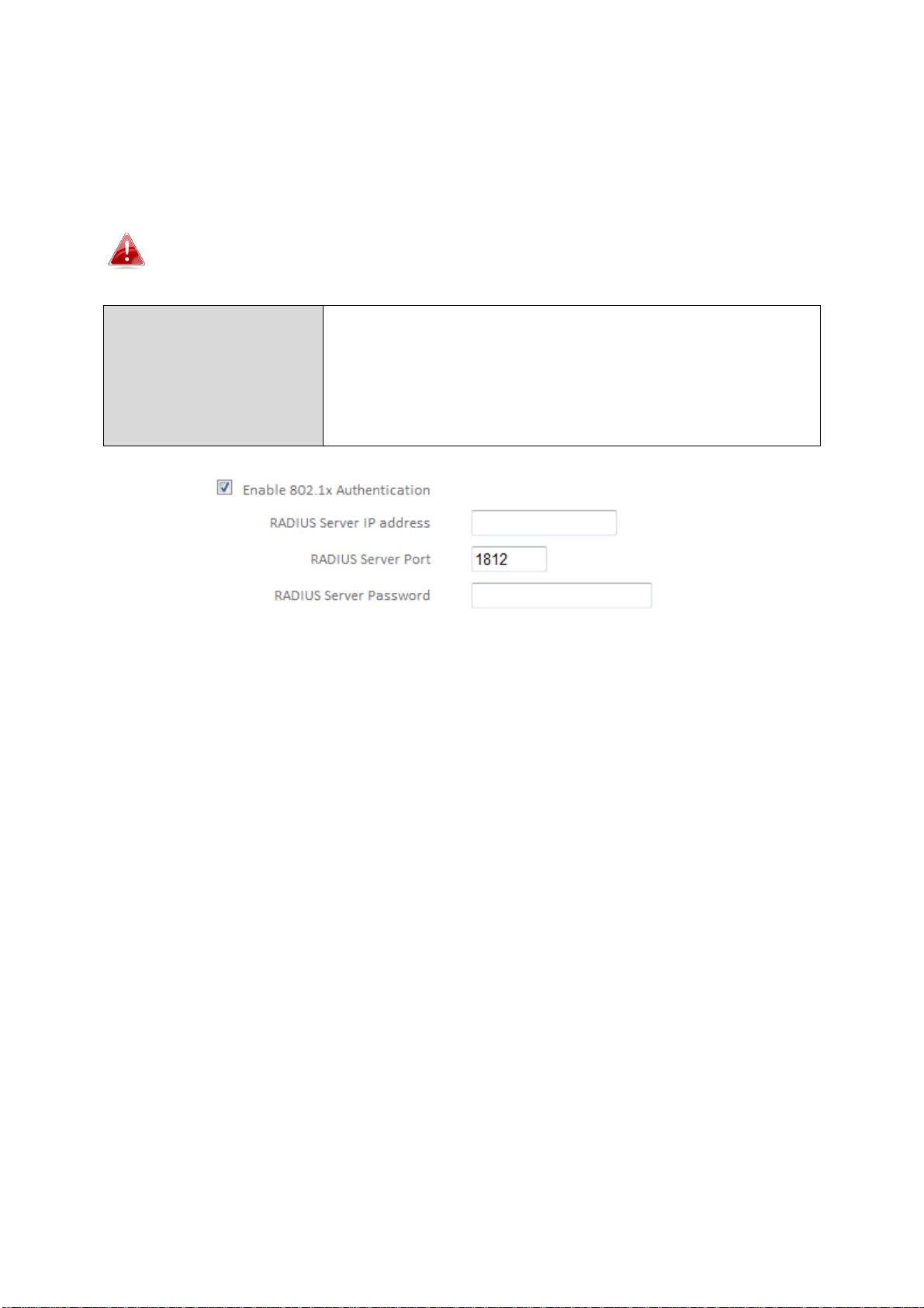
III-3-5-1-1. Disable
Enable 802.1x
Authentication
Check the box to enable the 802.1x
authentication. A RADIUS server is required to
perform 802.1x authentication: enter the
RADIUS server’s information in the relevant
fields (below).
Encryption is disabled and no password/key is required to connect to the
BR-6478 AC V2.
Disabling wireless encryption is not recommended. When
disabled, anybody within range can connect to your device’s SSID.
73
Page 78

III-3-5-1-2. WEP
Key Length
Select 64-bit or 128-bit. 128-bit is more secure
than 64-bit.
Key Format
Choose from “ASCII” (any alphanumerical
character 0-9, a-z and A-Z) or “Hex” (any
characters from 0-9, a-f and A-F).
Encryption Key
Enter your encryption key/password according
to the format you selected above. A complex,
hard-to-guess key is recommended. Check the
“Hide” box to hide your password from being
displayed on-screen.
Enable 802.1x
Authentication
Check the box to enable the 802.1x
authentication. A RADIUS server is required to
perform 802.1x authentication: enter the
RADIUS server’s information in the relevant
fields (below).
WEP (Wired Equivalent Privacy) is a basic encryption type. For a higher
level of security consider using WPA encryption.
74
Page 79

III-3-5-1-3. WPA Pre-Shared Key
WPA Unicast
Cipher Suite
Select from WPA (TKIP), WPA2 (AES) or WPA2
Mixed. WPA2 (AES) is safer than WPA (TKIP),
but not supported by all wireless clients. Please
make sure your wireless client supports your
selection. WPA2 (AES) is recommended
followed by WPA2 Mixed if your client does not
support WPA2 (AES).
Pre-shared Key
Format
Choose from “Passphrase” (8-63
alphanumeric characters) or “Hex” (up to 64
characters from 0-9, a-f and A-F).
Pre-shared Key
Please enter a key according to the format you
selected above. A complex, hard-to-guess key
is recommended. Check the “Hide” box to hide
your password from being displayed on-screen.
WPA pre-shared key is the recommended and most secure encryption
type.
75
Page 80

III-3-5-1-4. WPA Radius
WPA Unicast
Cipher Suite
Select from WPA (TKIP), WPA2 (AES) or WPA2
Mixed. WPA2 (AES) is safer than WPA (TKIP),
but not supported by all wireless clients. Please
make sure your wireless client supports your
selection. WPA2 (AES) is recommended
followed by WPA2 Mixed if your client does not
support WPA2 (AES).
RADIUS Server IP
address
Input the IP address of the RADIUS
authentication server here.
RADIUS Server Port
Input the port number of the RADIUS
authentication server here. The default value
is 1812.
RADIUS Server
Password
Input the password of the RADIUS
authentication server here.
WPA RADIUS is a combination of WPA encryption and RADIUS user
authentication. If you have a RADIUS authentication server, you can
authenticate the identity of every wireless client against a user database.
76
Page 81

III-3-5-2. Guest/Multiple SSID
Enable Guest SSID
Check/uncheck the box to enable/disable the
guest Wi-Fi network.
Wireless Guest
Name
Enter a reference/ID name for your guest
wireless network.
Hide SSID
Enable or disable hide SSID. When disabled,
the SSID will be visible to clients as an available
Wi-Fi network. When enabled, the SSID will not
be visible as an available Wi-Fi network to
clients – clients must manually enter the SSID
in order to connect. A hidden (disabled) SSID is
typically more secure than a visible (enabled)
SSID.
Enable Wireless
Check the box to enable wireless clients
You can setup an additional “Guest” Wi-Fi network so guest users can enjoy
Wi-Fi connectivity without accessing your primary network. The “Guest”
screen displays settings for your guest Wi-Fi network.
The guest network is separate from your primary network. The
settings for your primary network can be found in the “Basic”
menu.
In access point mode, the “Guest” feature in the menu is replaced
by “Multiple SSID”. The BR-6478 AC V2 supports up to four
additional SSIDs for each wireless band in access point mode.
77
Page 82

Clients Isolation
isolation. This prevents wireless clients
connected to the BR-6478 AC V2 from
communicating with each other and improves
security. Typically, this function is useful for
corporate environments or public hot spots
and can prevent brute force attacks on clients’
usernames and passwords.
Band
Displays the wireless standard used for the
BR-6478 AC V2’s frequency band:
2.4GHz (B+G+N): Allows 802.11b, 802.11g, and
802.11n wireless clients to connect to the
BR-6478 AC V2.
Channel Number
Channel number for the guest network is the
same as the main SSID and cannot be adjusted
independently.
Encryption
Please refer to III-3-5-1. Basic: Wireless
Security for details about security settings.
WPA RADIUS encyrption type is not available for the guest
network.
MULTIPLE SSID:
The BR-6478 AC V2 supports up to four additional SSIDs for each wireless
band in access point mode. Once configured, these SSIDs are displayed in the
“Multiple SSID Status” table as shown below. Use the “Multiple SSID Basic
Settings” box to configure additional SSIDs.
78
Page 83

Multiple SSID
Use the drop down menu to select which SSID
(numbered 1 – 4) to configure.
Enable Multiple
SSID
Check/uncheck this box to enable/disable the
specified SSID. Must be checked for the SSID to
function.
Wireless Network
Name (SSID)
Enter a reference/ID name to separate your
wireless network.
Enable Wireless
Clients Isolation
Check the box to enable wireless clients
isolation. This prevents wireless clients
connected to the BR-6478 AC V2 from
communicating with each other and improves
security. Typically, this function is useful for
corporate environments or public hot spots
and can prevent brute force attacks on clients’
usernames and passwords.
Band
Displays the wireless standard used for the
BR-6478 AC V2’s frequency band:
2.4GHz (B+G+N): Allows 802.11b, 802.11g, and
802.11n wireless clients to connect to the
BR-6478 AC V2.
Channel Number
Channel number for the guest network is the
same as the main SSID and cannot be adjusted
independently.
VLAN ID
Set a VLAN ID for the specified SSID (see
below).
79
Page 84

A VLAN is a local area network which maps workstations virtually
instead of physically and allows you to group together or isolate
users from each other. VLAN IDs 0 – 4094 are supported.
Set wireless security for the specified SSID – security settings are
described in III-3-5-1. Basic.
80
Page 85

III-3-5-3. WPS
Enable WPS
Check/uncheck this box to enable/disable
WPS.
WPS Status
Displays “Configured” or “unConfigured”
depending on whether WPS and SSID/security
settings for the device have been configured or
not, either manually or using the WPS button.
Self PIN Code
Displays the WPS PIN code of the device.
SSID
Displays the SSID of the device.
Authentication
Mode
Displays the wireless security authentication
mode of the device.
Authentication Key
Displays the wireless security authentication
key.
Configuration
Mode
The configuration mode of the device’s WPS
setting is displayed here. “Registrar” means
the device acts as an access point for a wireless
client to connect to and the wireless client(s)
Wi-Fi Protected Setup is a simple way to establish connections between WPS
compatible devices. WPS can be activated on compatible devices by pushing a
WPS button on the device or from within the device’s firmware/configuration
interface. When WPS is activated in the correct manner and at the correct
time for two compatible devices, they will automatically connect. PIN code
WPS includes the use of a PIN code between the two devices for verification.
81
Page 86

will follow the device’s wireless settings.
Configure via Push
Button
Click “Start PBC” (Push-Button Configuration)
to activate WPS on the access point. WPS will
be active for 2 minutes.
Configure via Client
PIN Code
Enter the wireless client’s PIN code here and
click “Start PIN” to activate PIN code WPS.
Refer to your wireless client’s documentation if
you are unsure of its PIN code.
III-3-5-4. Access Control
Access Point mode only
Access Control is a security feature that can help to prevent unauthorized
users from connecting to your wireless router.
This function allows you to define a list of network devices permitted to
connect to the BR-6478 AC V2. Devices are each identified by their unique
MAC address. If a device which is not on the list of permitted MAC addresses
attempts to connect to the BR-6478 AC V2, it will be denied.
To enable this function, check the box labeled “Enable Wireless Access
Control”.
82
Page 87

MAC address
Select a PC name from the drop-down list and
click “>>” to add enter it into the blank field to
the right.
Click “Refresh’ in the drop-down menu to
refresh the list of available MAC addresses. If
the address you wish to add is not listed, enter
it manually.
Enter a MAC address of computer or network
device manually without dashes or colons e.g.
for MAC address ‘aa-bb-cc-dd-ee-ff’ enter
‘aabbccddeeff’.
Comment
Enter a comment for reference/identification
consisting of up to 16 alphanumerical
characters.
Add
Click “Add” to add the MAC address to the
MAC address filtering table.
Delete Selected/
Delete All
Delete selected or all entries from the table.
MAC address entries will be listed in the table as shown below. Select an entry
using the “Select” checkbox.
83
Page 88

III-3-5-5. Schedule
When Cross-Band is enabled in extender mode, wireless
scheduling is reversed according to frequency. Your 2.4GHz
schedule will apply to your extender’s 5GHz network and
vice-versa.
The schedule feature allows you to automate the wireless radio to switch off
at specified times. Multiple schedules can be configured. Check/uncheck the
box “Enable Wireless Off Schedule” to enable/disable the wireless off
scheduling function.
The BR-6478 AC V2 must have time & date settings initially set to
use scheduling.
84
Page 89

Wireless scheduling can save energy and increase the security of
Add
Add the schedule to the table of active
schedules.
Delete Selected/
Delete All
Delete selected or all entries from the table
of active schedules.
your network.
1. Use the dropdown to select which day(s) to include in the schedule. Check
“Every Day” as a shortcut for an every day schedule.
2. Specify a start and end time (hour and minute) for the wireless off
schedule using the drop-down menu.
85
Page 90

III-3-6. USB
Connect your USB storage to the USB port on the rear of
the BR-6478AC V2. USB sharing is enabled by default so
devices on your network can access the USB storage drive
using appropriate tools for your OS (e.g. Windows File
Explorer Network).
USB drives should be pre-formatted to supported FAT32 or NTFS
file systems before use with the USB port. USB hubs are not
supported.
III-3-6-1. Basic Settings
Configure basic USB settings: you can use the USB port for USB storage or for
printer sharing. For USB storage you can enable Network Neighborhood
access for Windows, and FTP access.
86
Page 91

Enable USB Sharing
Enable or disable USB Sharing. This must be
enabled to use USB storage or printer sharing.
Select USB storage or printer sharing.
Enable Network
Neighborhood
Enable Network Neighborhood access for
Windows if you can’t find your USB storage on
a Windows device when connected to the
network.
FTP Server
Enable FTP access to the USB storage. Modify
the port number if required.
FTP Server
(Internet)
Enable remote (Internet) FTP access to the USB
storage. Modify the port number if required.
87
Page 92

III-3-6-2. Advanced Settings
Network Name
Edit the name of the USB storage in the
network.
Workgroup
Edit the name of the Network Neighborhood
workgroup for your USB storage.
Share All
Select to share all folders and content on your
USB storage.
Require
Authentication
Select to use password authentication to
access USB storage for all folders or only
specified folders. Click “Add” to setup
authentication.
You can configure advanced USB storage settings for access management
(folder access settings) and Network Neighborhood.
88
Page 93

USB Device
Displays the name of your attached USB
storage.
File System
Displays the file system configured on your USB
storage. FAT32 & NTFS are supported.
Share Name
Set a reference name for this sharing
configuration.
Folder Name
Specify whether to share all folders or only
selected folders. Browse to choose a specific
folder to share.
User Name
Select a username.
Password
Select a password.
Access Limit
Select access limit for this USB storage.
89
Page 94
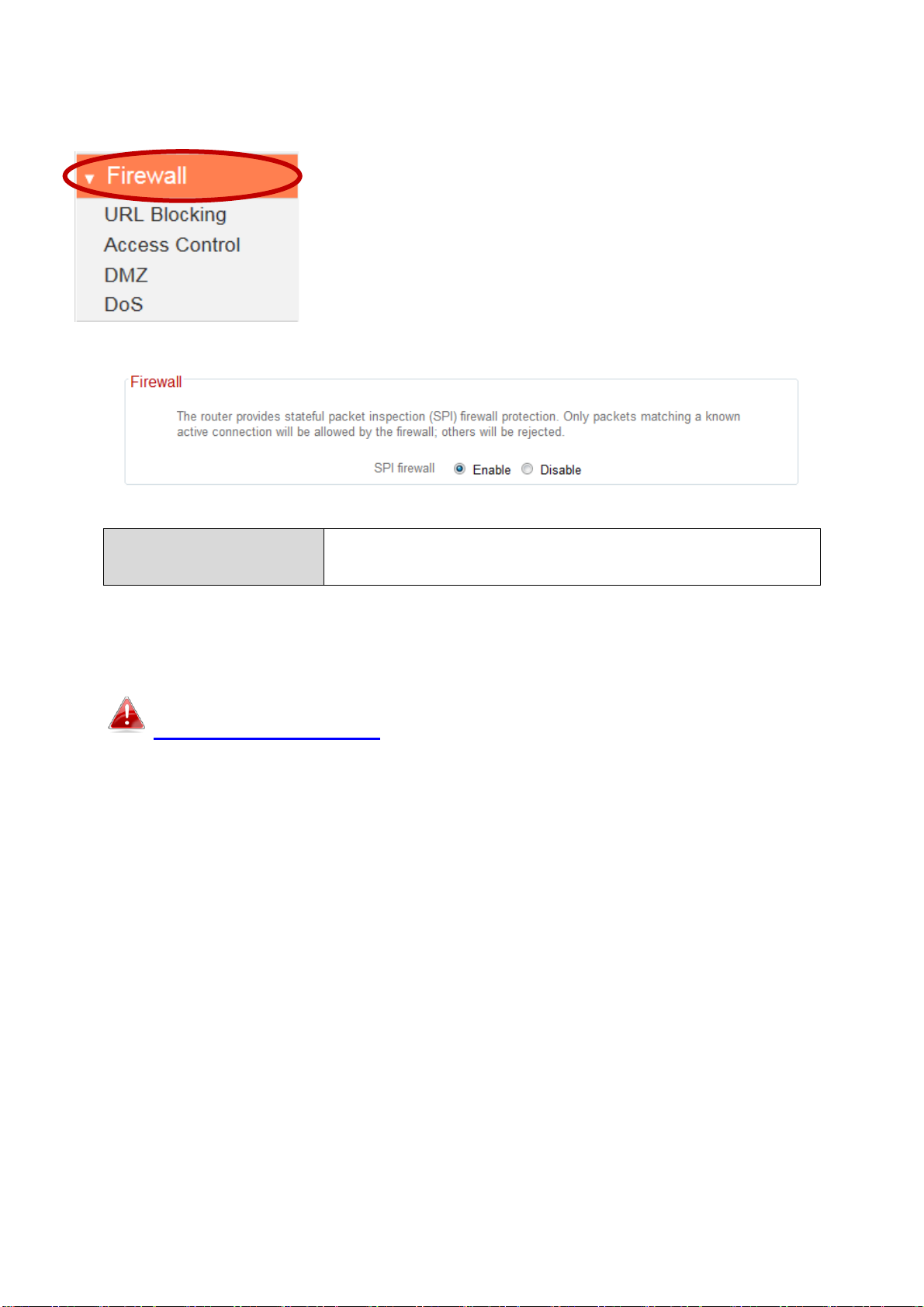
III-3-7. Firewall
SPI firewall
Enable or disable the Stateful Packet
Inspection (SPI) firewall.
The “Firewall” menu provides access to URL blocking,
access control, DMZ and DoS functions to improve
the security of your wireless network.
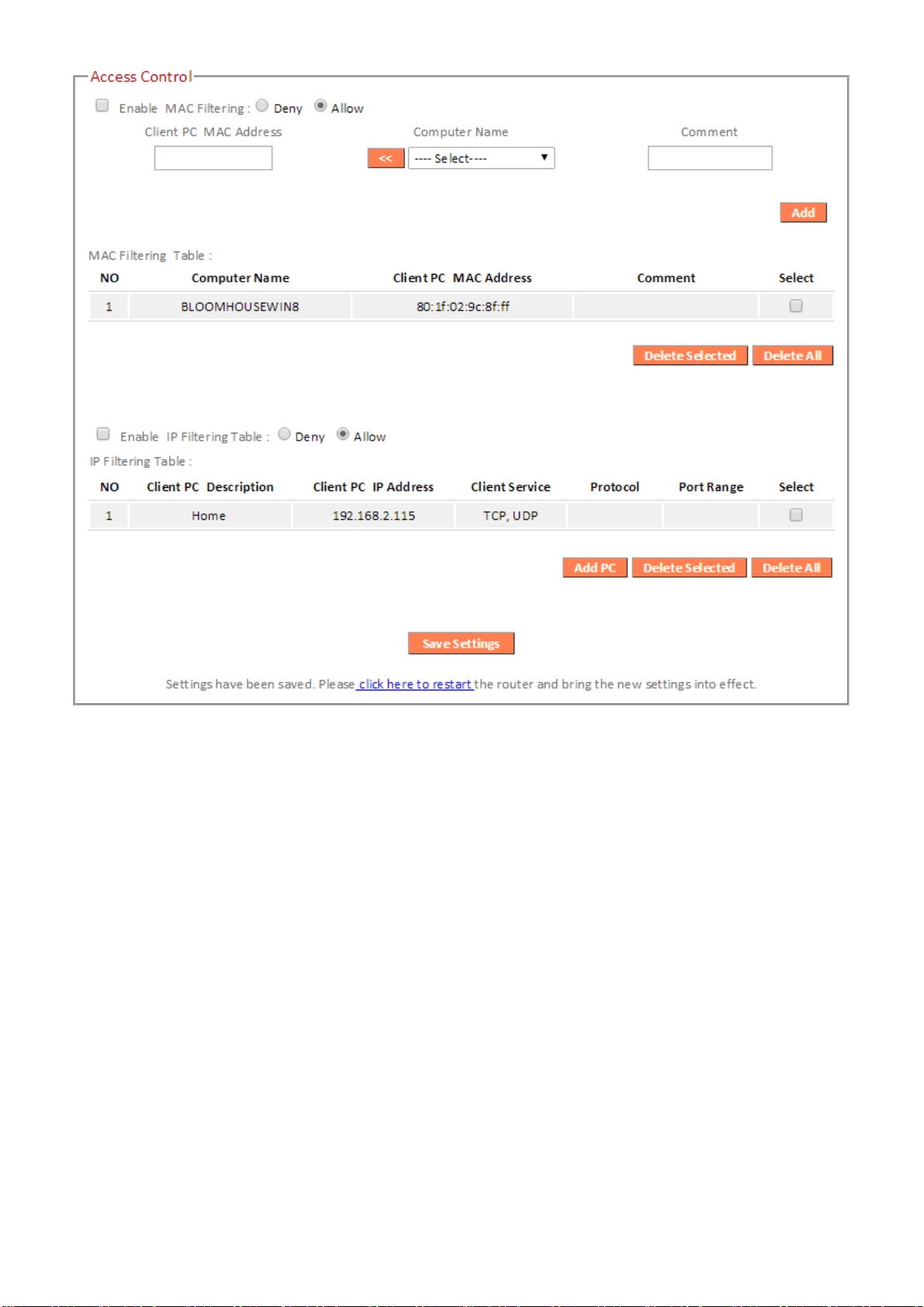
III-3-7-2. Access Control
Access Control (MAC filtering) can also be configured from
III-3-5-4. Access Control.
Access Control is a security feature that can help to prevent unauthorized
users from connecting to your wireless router.
This function allows you to define a list of network devices permitted or
denied to connect to the BR-6478 AC V2. Devices are each identified by their
unique MAC address or IP address. Specific services can also be
allowed/denied for IP addresses.
Check/uncheck the “Enable MAC Filtering” and/or “Enable IP Filtering” box to
enable/disable MAC filtering and/or IP filtering.
90
Page 95
91
Page 96

MAC Filtering:
Enable MAC
Filtering
Check the box to enable MAC filtering and
select whether to “Deny” or “Allow” access for
specified MAC address.
Client PC MAC
Address
Enter a MAC address of computer or network
device manually without dashes or colons e.g.
for MAC address ‘aa-bb-cc-dd-ee-ff’ enter
‘aabbccddeeff’.
Computer Name
Select a computer name from the drop-down
list and click “<<” to add its MAC address into
the “Client PC Mac Address” field.
Click “Refresh’ in the drop-down menu to
refresh the list of available MAC addresses. If
the address you wish to add is not listed, enter
it manually.
Comment
Enter a comment for reference/identification
consisting of up to 16 alphanumerical
characters.
Add
Click “Add” to add the MAC address to the
MAC address filtering table.
Delete Selected /
Delete All
Delete selected or all entries from the table.
MAC address entries will be listed in the table. Select an entry using the
“Select” checkbox.
92
Page 97
IP Filtering:
Enable IP Filtering
Check the box to enable IP filtering and select
whether to “Deny” or “Allow” access for
specified IP address.
Add PC
Opens a new window to add a new IP to the
list, to deny or allow access/services according
to above.
93
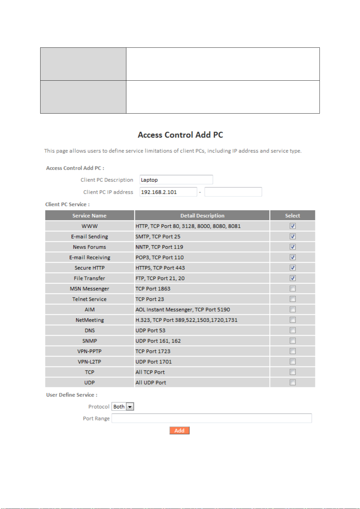
Page 98

Client PC
Description
Enter a description for reference/identification
of up to 16 alphanumeric characters.
Client PC IP address
Enter a starting IP address in the left field and
the end IP address in the right field to define a
range of IP addresses; or enter an IP address in
the left field only to define a single IP address.
Service Name
Various services are listed here with a short
description. Check/uncheck the box for each
service you wish to select.
Protocol
Select protocol “TCP” or “UDP” or “Both” for a
service not included in the “Client PC Service”
list.
Port Range
Enter the port range for the service not
included in the “Client PC Service” list.
Enter a single port number e.g. 110, a range of
port numbers e.g. 110-120, or multiple port
numbers separated by a comma e.g.
110,115,120.
Add
Click “Add” to add selected services or a user
defined service to the IP filtering table.
Delete Selected/
Delete All
Delete selected or all entries from the table.
IP filtering entries will be listed in the IP filtering table shown below.
94
Page 99

III-3-7-3. DMZ
Enable DMZ
Check/uncheck the box to enable/disable the
device’s DMZ function.
Public
Select “Dynamic IP” or “Static IP” here.
For “Dynamic IP” select an Internet connection
session from dropdown menu.
For “Static IP” enter the IP address that you
want to map to a specific private IP address.
Client PC
Enter the private IP address that the internet IP
address will be mapped to.
Computer Name
Select a computer name from the list and click
“<<” to enter its IP address into the “Client PC”
field (above).
Add
Click “Add” to add the client to the “Current
DMZ Table”.
A Demilitarized Zone (DMZ) is an isolated area in your local network where
private IP addresses are mapped to specified Internet IP addresses, allowing
unrestricted access to the private IP addresses but not to the wider local
network.
You can define a virtual DMZ host here. This is useful for example, if a
network client PC cannot run an application properly from behind an NAT
firewall, since it opens the client up to unrestricted two-way access.
95
Page 100

Delete Selected/
Delete All
Delete selected or all entries from the table.
DMZ entries will be displayed in the table shown below:
III-3-7-4. DoS
Denial-of-Service (DoS) is a common form of malicious attack against a
network. The router’s firewall can protect against such attacks.
If you are not familiar with these functions, it is recommended you keep the
default settings.
96
 Loading...