

Page 1

BR-6478AC
User Manual
02-2013 / v1.0
1
Page 2

Notice According to GNU General Public License Version 2
corresponding source code.
COPYRIGHT
Copyright Edimax Technology Co., Ltd. all rights reserved. No part of this publication
may be reproduced, transmitted, transcribed, stored in a retrieval system, or translated
into any language or computer language, in any form or by any means, electronic,
mechanical, magnetic, optical, chemical, manual or otherwise, without the prior written
permission from Edimax Technology Co., Ltd.
Edimax Technology Co., Ltd. makes no representations or warranties, either expressed or
implied, with respect to the contents hereof and specifically disclaims any warranties,
merchantability, or fitness for any particular purpose. Any software described in this
manual is sold or licensed as is. Should the programs prove defective following their
purchase, the buyer (and not this company, its distributor, or its dealer) assumes the
entire cost of all necessary servicing, repair, and any incidental or consequential damages
resulting from any defect in the software. Edimax Technology Co., Ltd. reserves the right
to revise this publication and to make changes from time to time in the contents hereof
without the obligation to notify any person of such revision or changes.
The product you have purchased and the setup screen may appear slightly different from
those shown in this QIG. For more information about this product, please refer to the
user manual on the CD-ROM. The software and specifications are subject to change
without notice. Please visit our website www.edimax.com for updates. All brand and
product names mentioned in this manual are trademarks and/or registered trademarks of
their respective holders.
Edimax Technology Co., Ltd.
Add: No. 3, Wu-Chuan 3rd Rd., Wu-Ku Industrial Park, New Taipei City, Taiwan
Tel: +886-2-77396888
Email: sales@edimax.com.tw
This product includes software that is subject to the GNU General Public License version
2. The program is free software and distributed without any warranty of the author. We
offer, valid for at least three years, to give you, for a charge no more than the costs of
physically performing source distribution, a complete machine-readable copy of the
2
Page 3

CONTENTS
I. PRODUCT INFORMATION ............................................................................................ 5
I-1. Package Contents ........................................................................................ 5
I-2. Hardware .................................................................................................... 6
I-3. LED Status ................................................................................................... 6
I-4. Safety Information ...................................................................................... 8
I-5. Features ...................................................................................................... 8
II. HARDWARE INSTALLATION & NETWORK SETTINGS ................................................... 9
II-1. Hardware Installation.................................................................................. 9
II-2. Network Settings ........................................................................................ 9
II-2-1. Windows XP................................................................................................ 9
II-2-2. Windows Vista .......................................................................................... 13
II-2-3. Windows 7 ................................................................................................ 14
II-2-4. Windows 8 ................................................................................................ 17
III. SETTING UP ............................................................................................................... 21
III-1. iQ Setup .................................................................................................... 21
III-2. Manual Setup via Web Browser ................................................................ 26
IV. BROWSER BASED CONFIGURATION INTERFACE ........................................................ 28
IV-1. Status ........................................................................................................ 28
IV-2. Setup Wizard ............................................................................................ 28
IV-3. Internet ..................................................................................................... 29
IV-3-1. WAN Setup ............................................................................................... 29
IV-3-1-1. Dynamic IP ................................................................................................ 31
IV-3-1-2. Static IP ..................................................................................................... 32
IV-3-1-3. PPPoE........................................................................................................ 33
IV-3-1-4. PPTP/L2TP ................................................................................................. 34
IV-3-1-5. WISP ......................................................................................................... 37
IV-3-2. DDNS ........................................................................................................ 37
IV-4. LAN ........................................................................................................... 39
IV-5. 2.4GHz W ireless ........................................................................................ 40
IV-5-1. Basic Settings ............................................................................................ 41
IV-5-1-1. Wireless Security ...................................................................................... 43
IV-5-1-1-1. WEP ...................................................................................................... 43
IV-5-1-1-2. WPA pre-shared key ............................................................................. 43
IV-5-1-1-3. WPA RADIUS ......................................................................................... 44
IV-5-2. Guest Wireless Settings............................................................................... 45
IV-5-3. WPS ............................................................................................................ 46
IV-5-4. Access Control............................................................................................. 46
IV-5-5. Wireless Schedule ....................................................................................... 47
IV-6. 5GHz Wireless ................................................................................................ 48
IV-7. Security .......................................................................................................... 50
IV-7-1. URL Blocking ............................................................................................... 50
3
Page 4

IV-7-2. Access Control............................................................................................. 51
IV-8. QoS (Quality of Service) ................................................................................. 52
IV-8-1. QoS ............................................................................................................. 52
IV-8-2. iQoS ............................................................................................................ 55
IV-9. Advanced ....................................................................................................... 56
IV-9-1. Static Routing .............................................................................................. 56
IV-9-2. Port Forwarding .......................................................................................... 57
IV-9-3. Virtual Server .............................................................................................. 57
IV-9-4. 2.4GHz Wireless .......................................................................................... 58
IV-9-5. 5GHz Wireless ............................................................................................. 60
IV-9-6. ALG ............................................................................................................. 60
IV-9-7. IGMP ........................................................................................................... 61
IV-9-8. DMZ ............................................................................................................ 61
IV-9-9. Firewall ....................................................................................................... 62
IV-9-10. UPnP ......................................................................................................... 63
IV-10. Administration ............................................................................................. 64
IV-10-1. Time Zone ................................................................................................. 64
IV-10-2. Password ................................................................................................... 64
IV-10-3. Remote Access .......................................................................................... 65
IV-10-4. Backup / Restore ....................................................................................... 65
IV-10-5. Upgrade .................................................................................................... 66
IV-10-6. Restart ...................................................................................................... 66
IV-10-7. Logs ........................................................................................................... 67
IV-10-8. Active DHCP Client .................................................................................... 67
IV-10-9. Statistics .................................................................................................... 68
V. TROUBLESHOOTING .............................................................................................. 69
VI. GLOSSARY ............................................................................................................ 70
4
Page 5
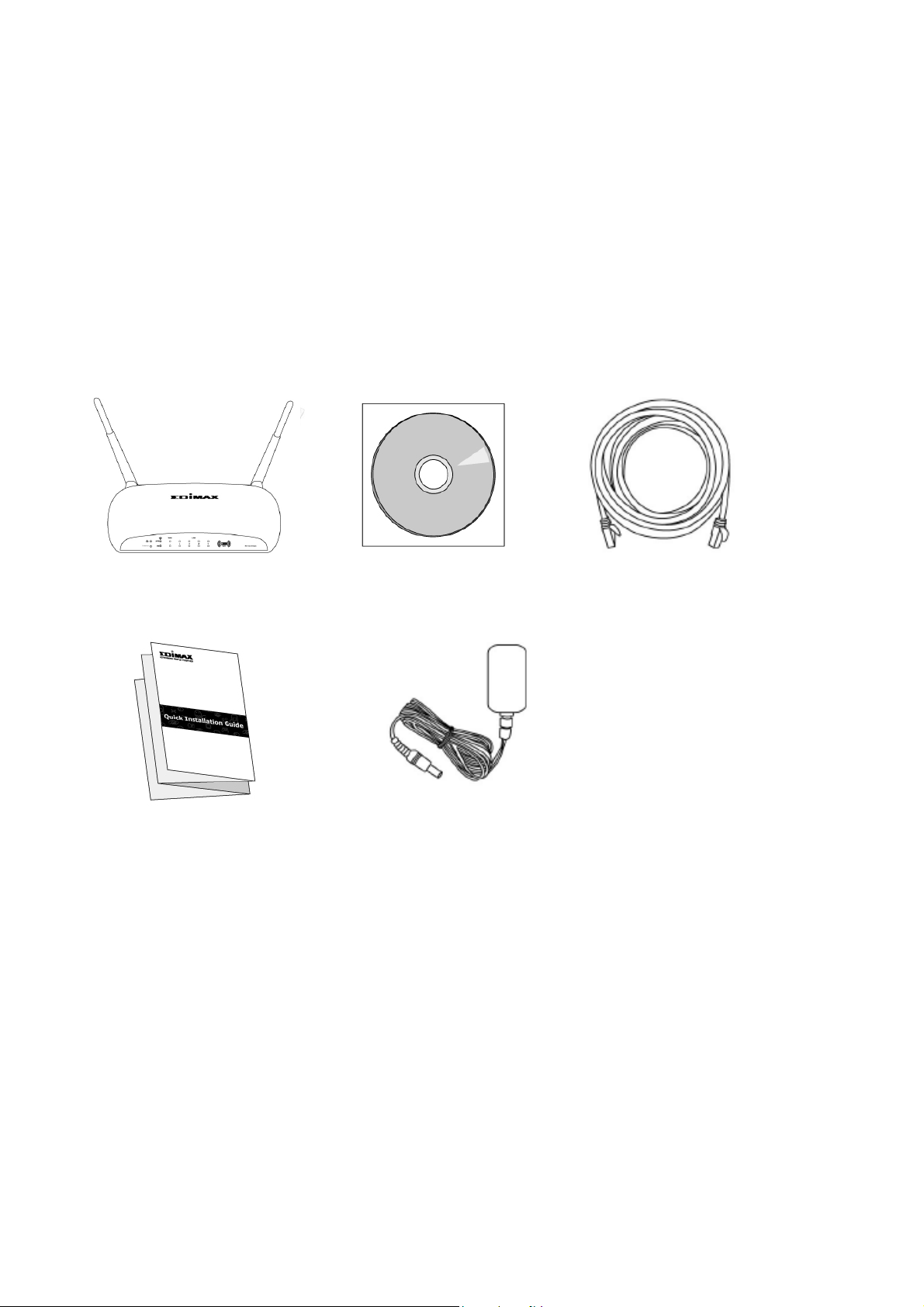
BR-6478AC
Ethernet
CD-ROM
Quick Installation Guide
Power Adapter
I. PRODUCT INFORMATION
Thank you for purchasing an Edimax BR-6478AC AC1200 wireless concurrent
dual-band gigabit router.
I-1. Package Contents
Before you start using this product, please check if there is anything missing in
the package, and contact your dealer to claim the missing item(s):
5
Page 6

Item Name
Description
Antenna
Connects
the supplied
3
dBi antennas.
Radio
ON/OFF Switch
Switch the wireless signal on/off accordingly.
Reset / WPS Button
Resets
the
router
to factory default settings (clears all
the WPS function.
Gigabit
LAN Port
s Connects
via Ethernet cable to a co
mputer or other
ne
twork devices
. Gigabit WAN Port
Connects to cable/xDSL modems.
5V Power Port
Connects to the supplied power adapter.
I-2. Hardware
settings) or starts the WPS function.
I-3. LED Status
Reset: Press and hold for 12 seconds to restore all
settings to factory defaults.
WPS: Press this button for 2–5 seconds to activate
6
Page 7

LED
LED Status
Description
On Interne
t connection
is active
. Flashing
Router is connecting to
internet
.
WAN activity
(transferring/receiving data)
On LAN port connec
ted.
LAN activity (transferring or
receiving data).
LAN port not connected.
Power
Internet
2.4 GHz
On Router is on.
Off Router is off.
Off No internet connection.
On 2.4GHz wireless is active.
2.4GHz LAN activity
Flashing
(transferring/receiving data).
Off 2.4GHz wireless is not active.
5 GHz
WAN
LAN 1–4
On 5GHz wireless is active.
5GHz LAN activity
Flashing
(transferring/receiving data).
Off 5GHz wireless is not active.
On WAN port connected.
Flashing
Off WAN port not connected.
Flashing
Off
7
Page 8

I-4. Safety Information
In order to ensure the safe operation of the device and its users, please read
and act in accordance with the following safety instructions.
1. The router is designed for indoor use only; do not place the router
outdoors.
2. Do not place the router in or near hot/humid places, such as a kitchen or
bathroom.
3. Do not pull any connected cable with force; carefully disconnect it from the
router.
4. The device contains small parts which are a danger to small children under
3 years old. Please keep the router out of reach of children.
5. Do not place the router on paper, cloth, or other flammable materials. The
router will become hot during use.
6. There are no user-serviceable parts inside the router. If you experience
problems with the router, please contact your dealer of purchase and ask
for help.
7. The router is an electrical device and as such, if it becomes wet for any
reason, do not attempt to touch it without switching the power supply off.
Contact an experienced electrical technician for further help.
8. If you smell burning or see smoke coming from the router then unplug the
router immediately, as far as it is safely possible to do so. Call your dealer of
purchase for help.
I-5. Features
• Supports IEEE 802.11ac & IEEE 802.11a/b/g/n concurrent dual-band
connections on 2.4GHz and 5GHz bands.
• Wireless data transmission rate up to 1167Mbps (2.4GHz 300Mbps + 5GHz
867Mbps).
• 4 gigabit LAN ports (data transmission rates up to 1000Mbps).
• Comply with IEEE 802.3/ 802.3u/ 802.3ab standards.
• Smart and automated iQ Setup.
• iQoS for quick and easy bandwidth management.
• Build-in hardware button to enable/disable the wireless signal.
• Wireless signal on/off scheduling function.
• Supports DHCP, Static IP, PPPoE, PPTP, L2TP and WISP connection modes.
8
Page 9
• Supports WMM, WEP, WPA, WPA2, DDNS, QoS, IP/MAC filter, DMZ and
virtual server.
II. HARDWARE INSTALLATION & NETWORK SETTINGS
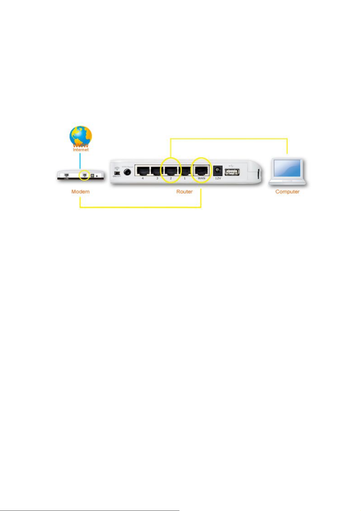
II-1. Hardware Installation
Please setup your router, computer, modem and other network devices as
shown below.
Before using the BR-6478AC, please make sure your computer is set to use a
dynamic IP address. This means your computer can obtain an IP address
automatically from a DHCP server. Please refer to instructions appropriate for
your operating system.
II-2. Network Settings
II-2-1. Windows XP
1. Click the “Start” button, then click “Control Panel”.
9
Page 10
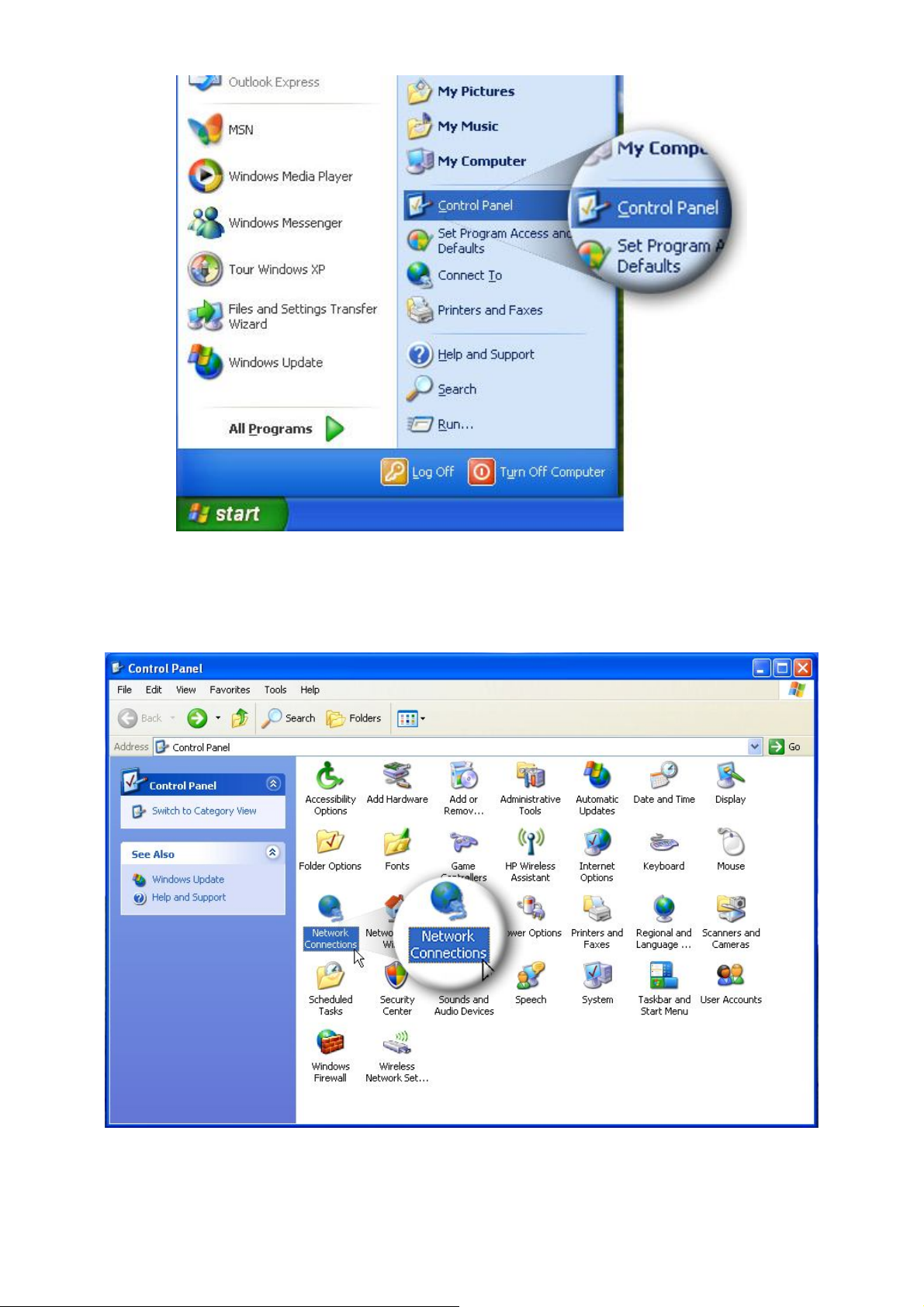
2. Double click the “Network Connections” icon and the “Network
Connections” window will appear.
3. Right click “Local Area Connection” on the mouse. When the “Local Area
Connection Properties” window appears, click “Properties”.
10
Page 11
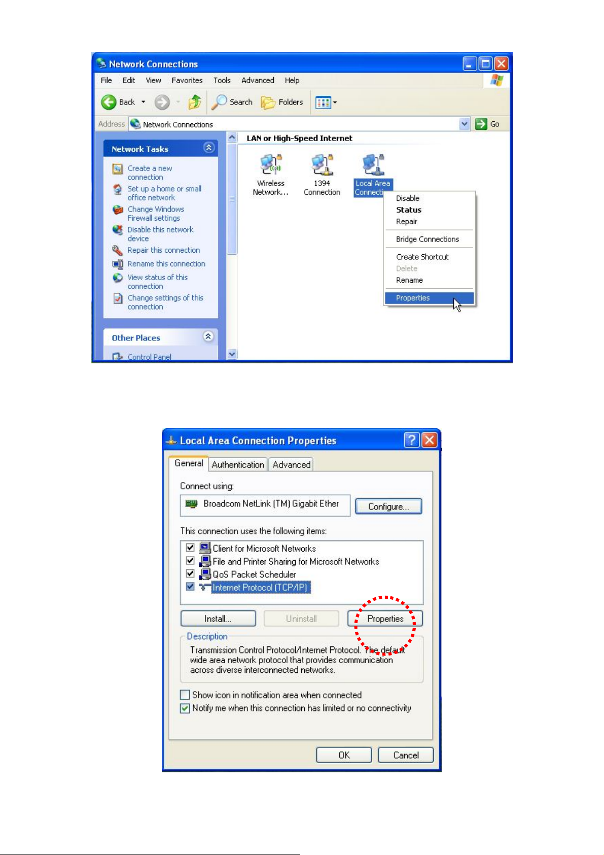
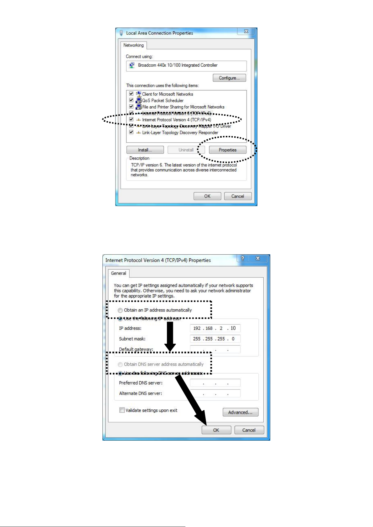
4. Select “TCP/IP” and click “Properties”.
5. Select “Obtain an IP address automatically” and “Obtain DNS server
11
Page 12
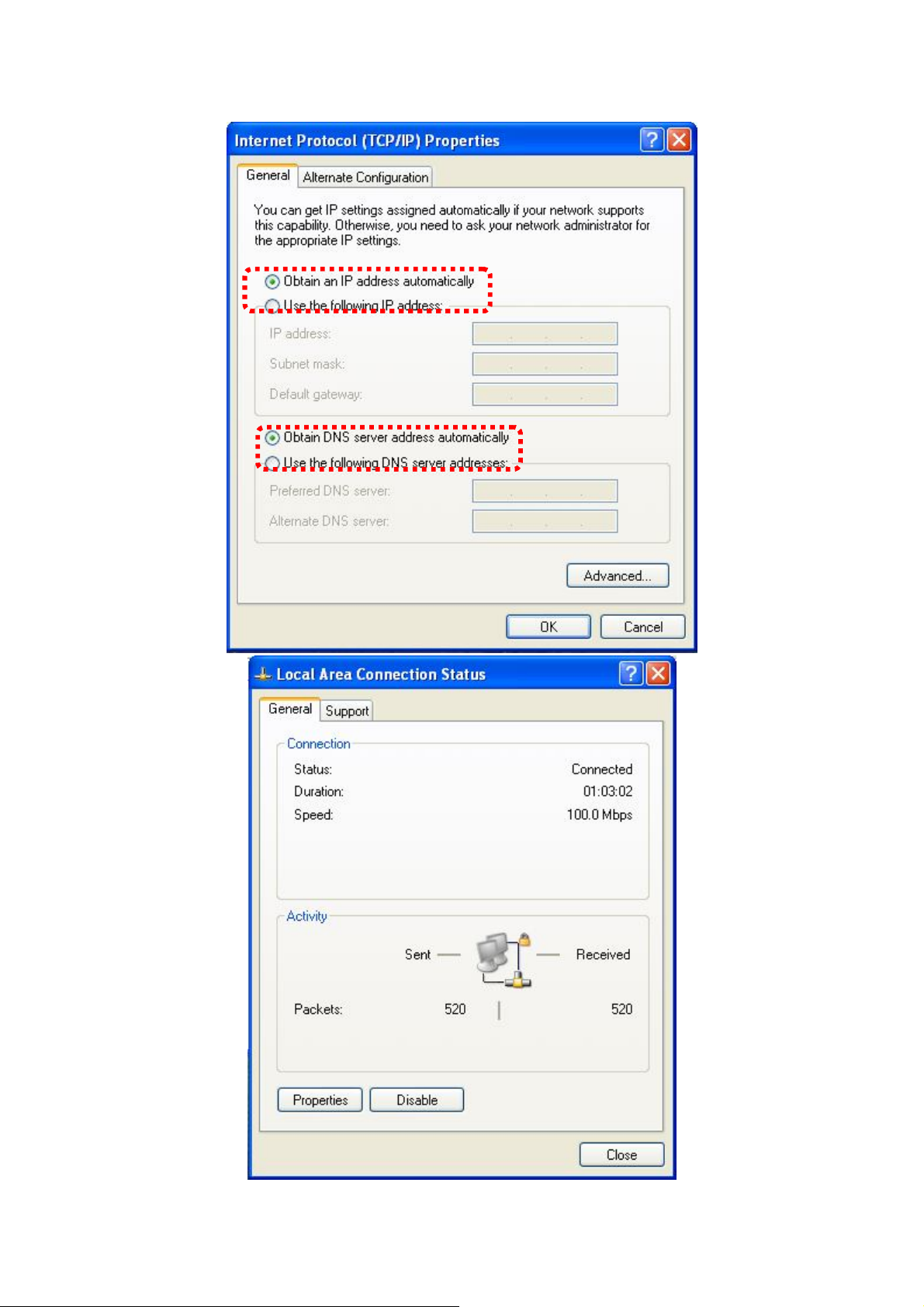
address automatically”, then click “OK”.
12
Page 13
II-2-2. Windows Vista
1. Click the “Start” button (it should be located in the lower-left corner of your
computer), then click “Control Panel”. Click “View Network Status and
Tasks”, then click “Manage Network Connections”. Right-click “Local Area
Network”, then select “Properties”. The “Local Area Connection Properties”
window will then appear, select “Internet Protocol Version 4 (TCP / IPv4)”,
and then click “Properties”.
2. Select “Obtain an IP address automatically” and “Obtain DNS server
address automatically”, then click “OK”.
13
Page 14

II-2-3. Windows 7
1. Click the “Start” button (it should be located in the lower-left corner of your
computer), then click “Control Panel”.
14
Page 15
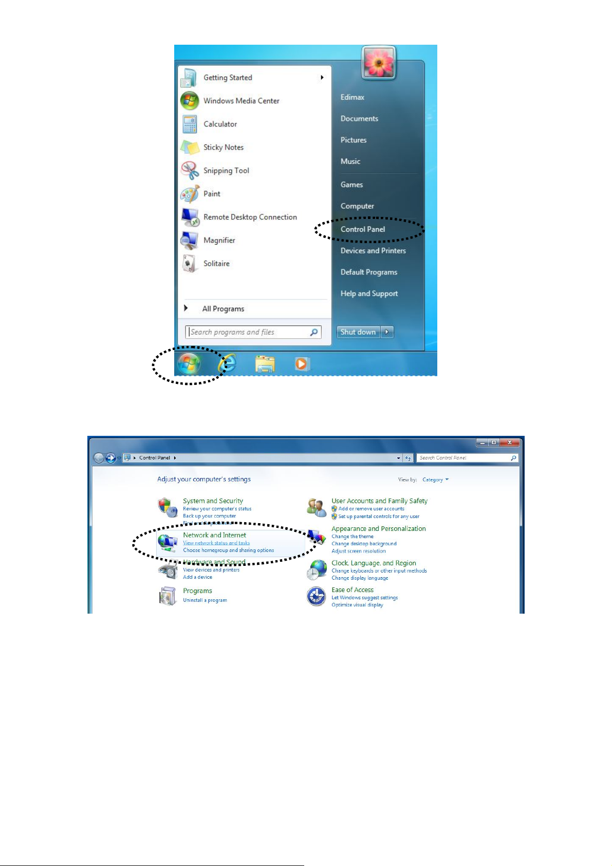
2. Under “Network and Internet” click “View network status and tasks”.
3. Click “Local Area Connection”.
15
Page 16
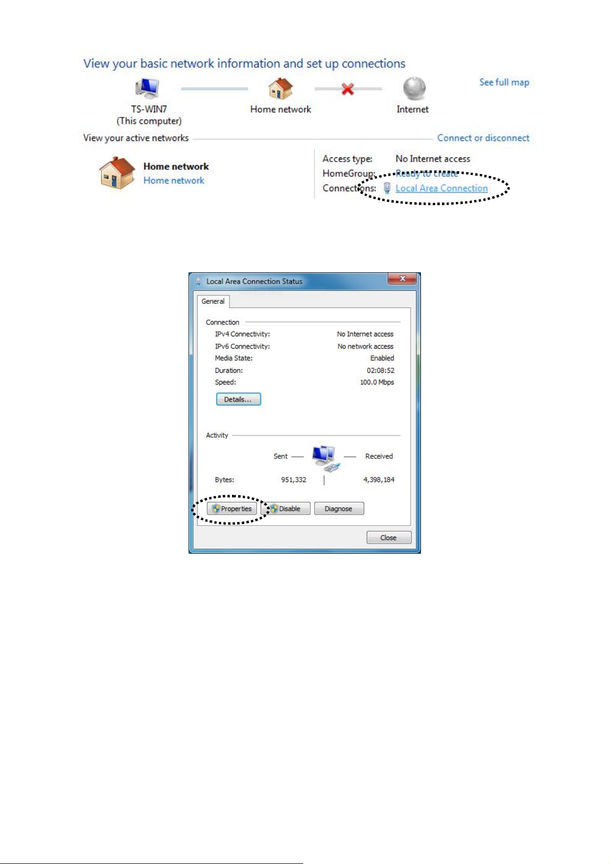
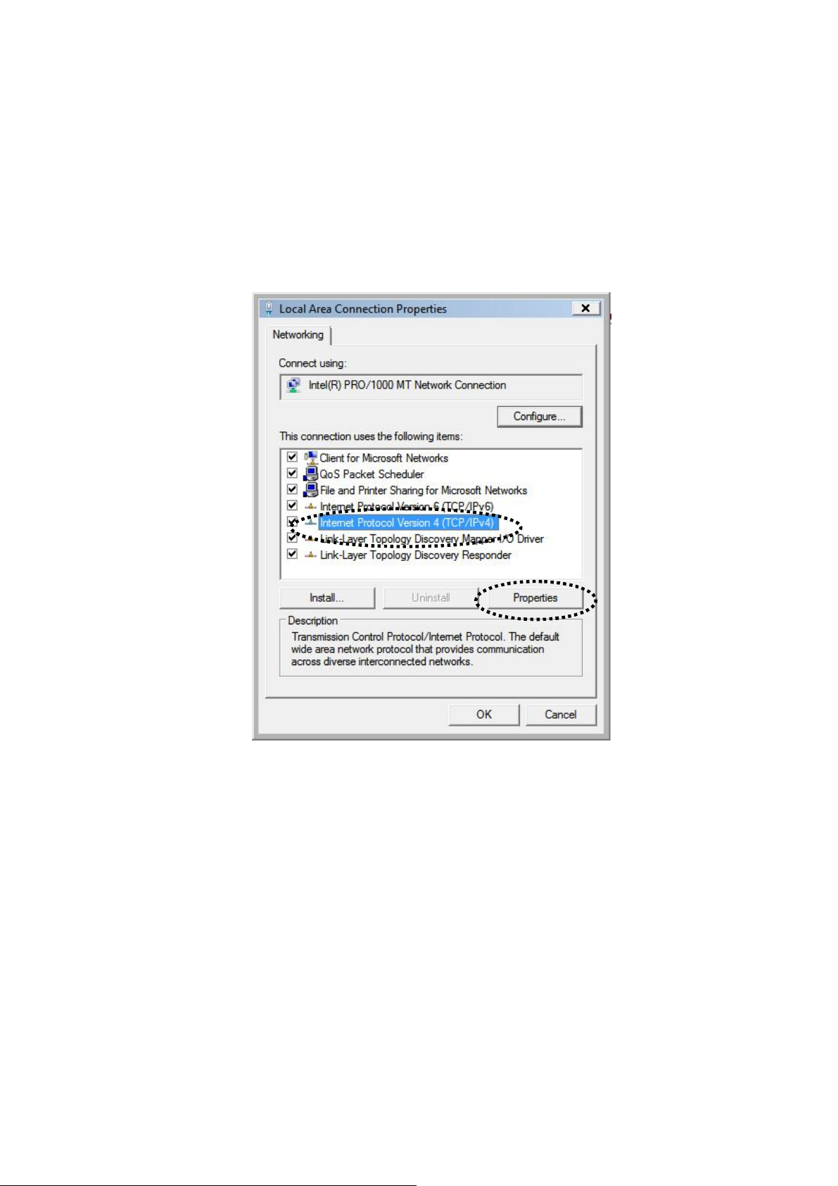
4. Click “Properties”.
5. Select “Internet Protocol Version 4 (TCP/IPv6) and then click “Properties”.
16
Page 17
6. Select “Obtain an IP address automatically” and “Obtain DNS server
address automatically”, then click “OK”.
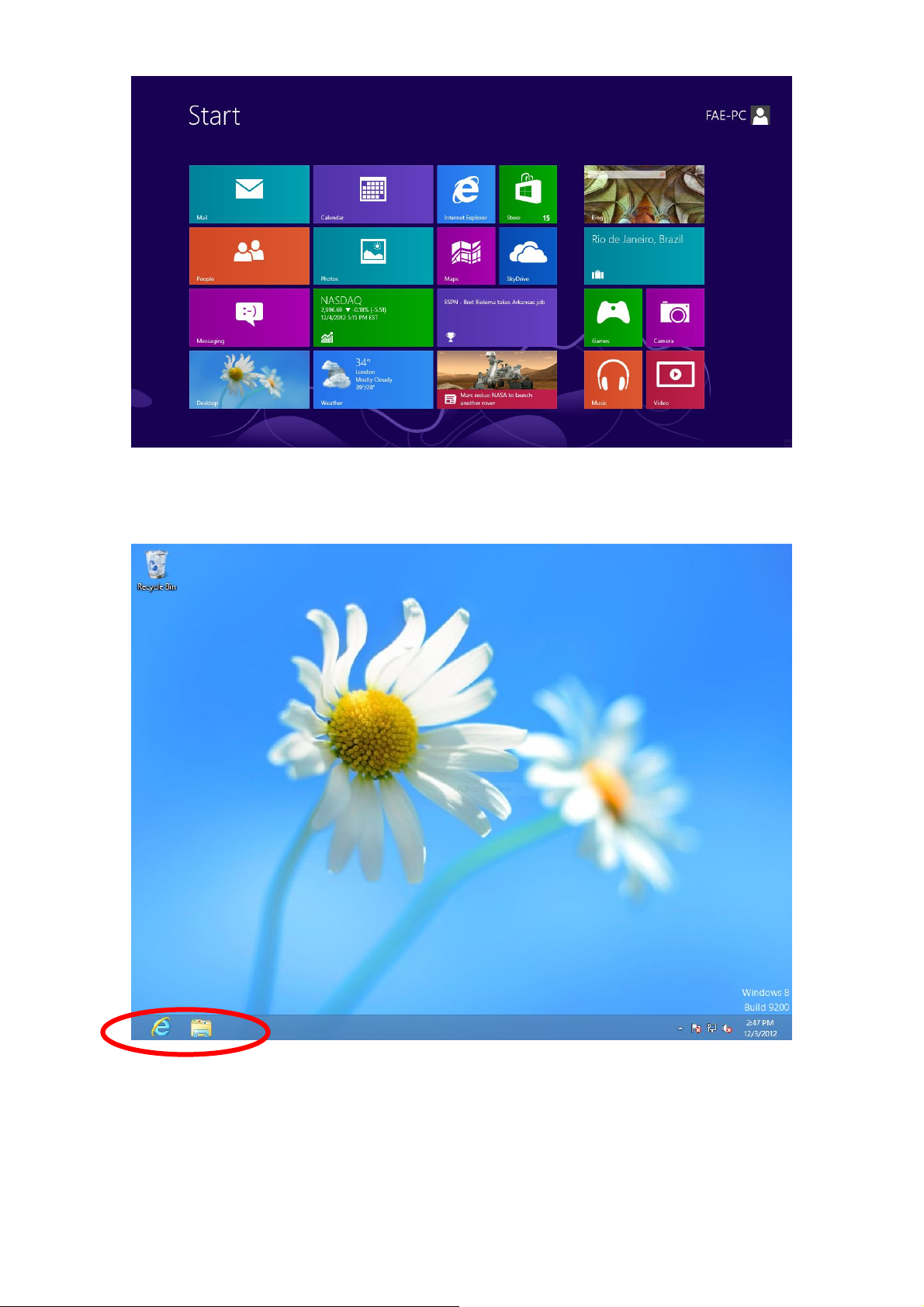
II-2-4. Windows 8
1. From the Windows 8 Start screen, you need to switch to desktop mode.
Move your curser to the bottom left of the screen and click.
17
Page 18
2. In desktop mode, click the File Explorer icon in the bottom left of the
screen, as shown below.
3. Right click “Network” and then select “Properties”.
18
Page 19
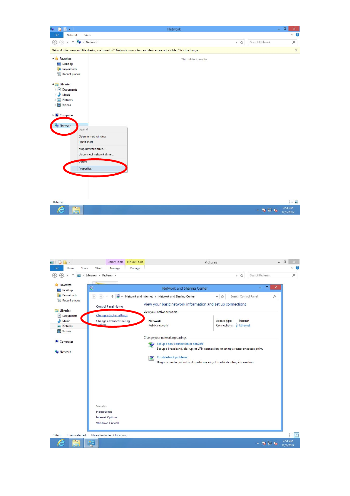
4. In the window that opens, select “Change adapter settings” from the left
side.
5. Choose your connection and right click, then select “Properties”.
19
Page 20
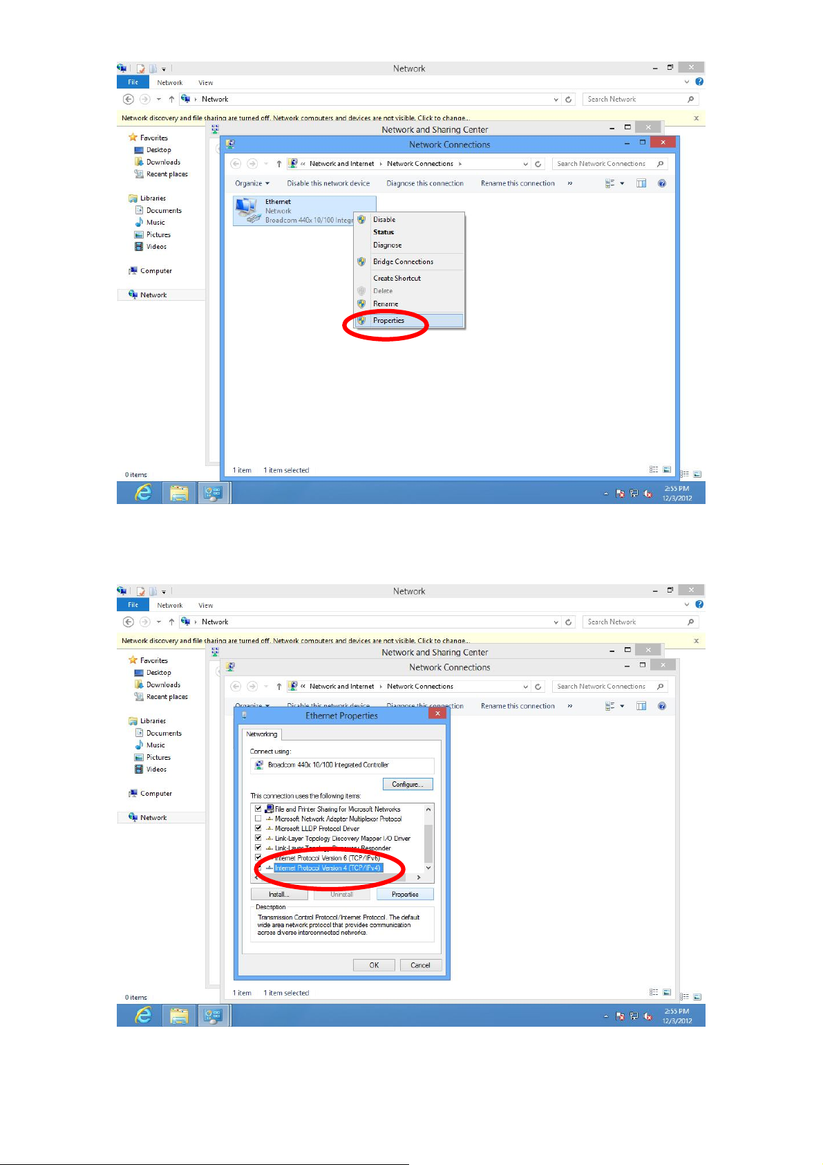
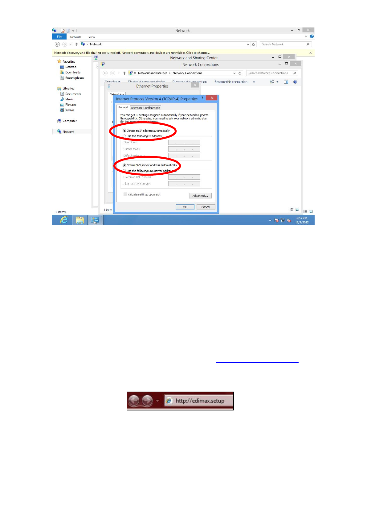
6. Select “Internet Protocol Version 4 (TCP/IPv6) and then click “Properties”.
7. Select “Obtain an IP address automatically” and “Obtain DNS server address
automatically”, then click “OK”.
20
Page 21
III. SETTING UP
III-1. iQ Setup
iQ Setup is a simple and intelligent WAN detection tool. Please follow the
instructions below.
1. Use a Wi-Fi device (e.g. computer, tablet, smartphone) to search for a Wi-Fi
network with the SSID “edimax.setup” and connect to it.
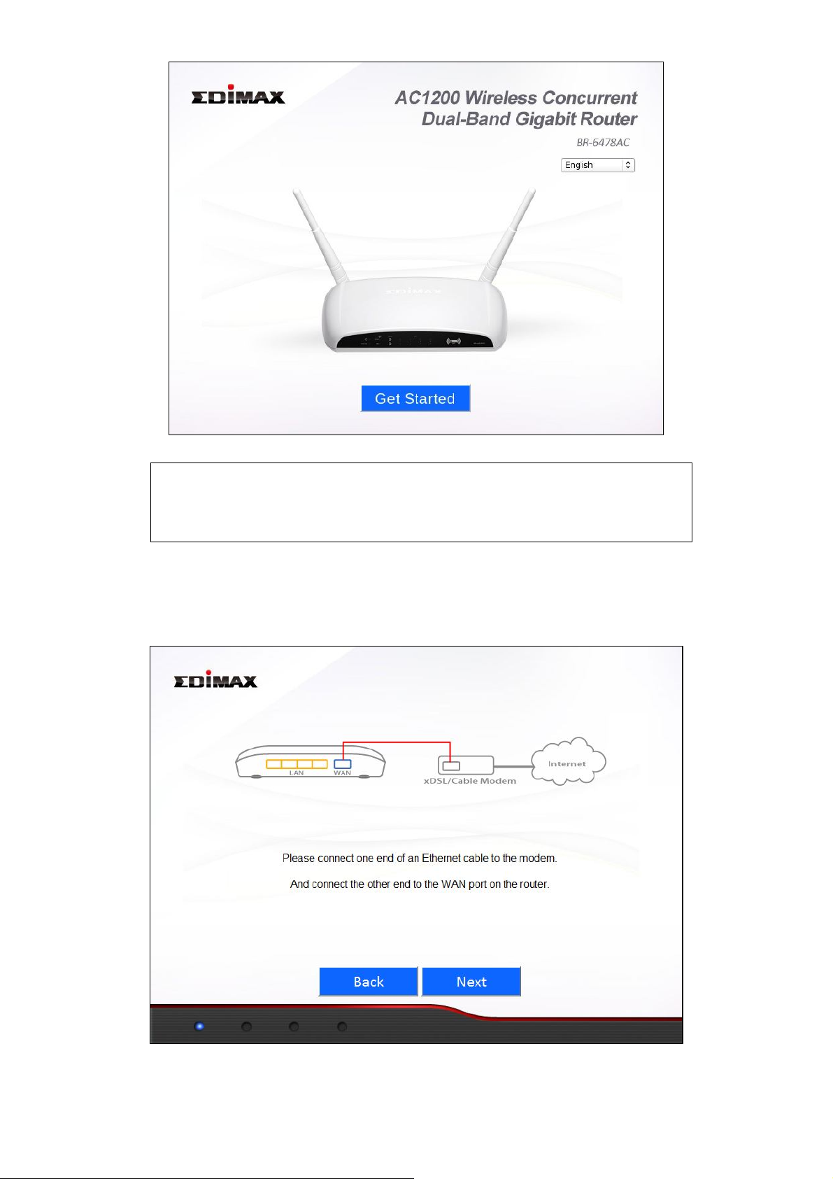
2. Open a web browser and if you do not automatically arrive at the “Get
Started” screen shown below, enter the URL http://edimax.setup. Select
your language from the drop down menu and click “Get Started” to begin
the setup process.
21
Page 22
Note: If you cannot access http://edimax.setup , please
make sure your computer is set to use a dynamic IP
address. See II. NETWORK SETTINGS
3. Ensure that your router is properly connected to your modem as shown on
the screen, and click “Next” to continue.
22
Page 23

4. Please wait a moment while the BR-6478AC detects your WAN connection
type.
5. The BR-6478AC will display the next screen depending on your WAN
connection type.
For Dynamic IP users please click “Next” to continue:
23
Page 24

For PPPoE users please enter the username and password provided by
your ISP and click “Next” to continue:
For other users please select your WAN connection type manually
from the drop down menu, click “Next” to continue and follow the
on-screen instructions.
Note: If you are not sure which WAN connection type
to choose, please contact your ISP.
24
Page 25

6. Please enter a network name (SSID) and Wi-Fi Password for each of the
BR-6478AC’s 2.4GHz and 5GHz Wi-Fi networks and click “Next” to
continue.
Note: Please remember these details. For your
convenience, you can write them down at the end of
this QIG in “Wi-Fi Settings”.
7. You will see the screen below, displaying a summary of your W-Fi settings
and that configuration is now complete. Please click “Next” to continue.
25
Page 26

8. You will see a final “Congratulations” screen and configuration is now
complete. Please close your browser window.
III-2. Manual Setup via Web Browser
1. Enter “192.168.2.1” in the web browser’s address bar and press “Enter”.
2. Input the username “admin” and the password “1234” and click “OK”..
26
Page 27

3. Input the username “admin” and the password “1234” and click “OK”. You
will arrive the at Status page, use the menu on the left side of the screen to
navigate. You can also change the language using the drop down menu in
the top right corner. Refer to IV. BROWSER BASED CONFIGURATION
INTERFACE.
27
Page 28

IV. BROWSER BASED CONFIGURATION INTERFACE
Once you have setup the router as detailed in III-1. iQ Setup or the included
QIG, you can further configure the settings of the router or run iQ Setup again
using the browser based configuration interface. If you prefer, you can also
skip iQ Setup and configure the router manually.
IV-1. Status
The Status page shows the basic status and information of the router.
Note: Screenshots shown in this manual are examples.
The information you see on your screen will be unique
to your configuration.
IV-2. Setup Wizard
To perform iQ Setup again and reconfigure the router, select “Setup Wizard”
from the menu on the left side.
28
Page 29

You will see the screen below. Please refer back to III-I iQ Setup onwards for
guidance on iQ Setup.
IV-3. Internet
IV-3-1. WAN Setup
Select a Wide Area Network (WAN) connection mode from the drop down
menu. After you select your connection mode and complete the configuration,
the router will restart for the changes to take effect.
Note: If you are not sure which WAN connection mode
you should use, please contact your Internet Service
Provider (ISP).
29
Page 30

Dynamic IP Select “Dynamic IP” if your Internet Service Provider
assigns an IP address to you automatically using DHCP
(Dynamic Host Configuration Protocol) (e.g. cable
internet providers).
Static IP Select “Static IP” if your ISP provides you with a fixed IP
address.
PPPoE Select “PPPoE” if your ISP provides internet access via
Point-to-Point Protocol over Ethernet (PPPoE) (usually
ADSL users).
PPTP Select “PPTP” if your ISP provides internet access via
Point-to-Point Tunneling Protocol (PPTP).
L2TP Select “L2TP” if your ISP provides internet access via
Layer 2 Tunneling Protocol (L2TP)
WISP Select “WISP” if your ISP provides wireless internet
access.
30
Page 31

IV-3-1-1. Dynamic IP
Host Name Input the host name of your computer (only required if
your ISP instructs you to do so).
MAC Address If your ISP only permits computers with certain MAC
addresses to access the internet, input the MAC
address of your computer here. If your computer is
connected to internet via cable modem, click “Clone
Mac address” to enter the MAC address automatically.
DNS address Select “Obtain an IP address automatically” or “Use the
following IP address”. If you choose “Use the following
IP address”, you will need to complete the “DNS1
Address”, “DNS2 Address” and “DNS3 Address” fields
below.
DNS1 Input the address of DNS1 assigned by your ISP.
DNS2 Input the address of DNS2 assigned by your ISP.
DNS3 Input the address of DNS3 assigned by your ISP.
MTU Input the MTU (maximum transmission unit) value of
your network connection. The default value, which is
typical for a dynamic IP or static IP, is 1500.
TTL Enable the “TTL” function if your ISP requires you to do
so.
31
Page 32

Most Dynamic IPs assigned to users by ISPs are configuration free
IV-3-1-2. Static IP
IP Address Input the static IP address assigned by your ISP.
Subnet Mask Input the subnet mask assigned by your ISP.
Default Gateway Address Input the default gateway address assigned by
your ISP.
MAC Address If your ISP only permits computers with
certain MAC addresses to access the internet,
input the MAC address of your computer here.
If your computer is connected to internet via
cable modem, click “Clone Mac address” to
enter the MAC address automatically.
DNS1 Input the address of DNS1 assigned by your
ISP.
DNS2 Input the address of DNS2 assigned by your
ISP.
DNS3 Input the address of DNS3 assigned by your
ISP.
MTU Input the MTU (maximum transmission unit)
32
Page 33

value of your network connection. The default
value, which is typical for a dynamic IP or static
IP, is 1500.
TTL Enable the “TTL” function if your ISP requires
you to do so.
IV-3-1-3. PPPoE
User Name Enter the user name assigned by your ISP.
Password Enter the password assigned by your ISP.
MAC Address If your ISP only permits computers with certain MAC
addresses to access the internet, input the MAC
address of your computer here. If your computer is
connected to internet via cable modem, click “Clone
Mac address” to enter the MAC address automatically.
33
Page 34

DNS address Select “Obtain an IP address automatically” or “Use the
following IP address”. If you choose “Use the following
IP address”, you will need to complete the “DNS1
Address”, “DNS2 Address” and “DNS3 Address” fields
below.
DNS1 Input the address of DNS1 assigned by your ISP.
DNS2 Input the address of DNS2 assigned by your ISP.
DNS3 Input the address of DNS3 assigned by your ISP.
TTL Enable the “TTL” function if your ISP requires you to do
so.
Service Name Input the Service Name assigned by your ISP.
MTU Input the MTU (maximum transmission unit) value of
your network connection. The default value is 1392.
Typical values for ADSL are 1392 or 1492.
Connection Type Select connection type from:
“Continuous” – always connected.
“Connect on Demand” – connect when required.
“Manual” – connect and disconnect manually.
Idle Time Out For ”Connect on Demand” connection type, specify the
length of inactivity required to disconnect.
Enable Dual Wan Access
If your ISP provides a dual-WAN service, then check the box “Enable Dual Wan
Access” and enter the required information.
IV-3-1-4. PPTP/L2TP
Fields for PPTP and L2TP connections are the same – PPTP is used as an
example below.
34
Page 35

Obtain an IP address automatically:
Host Name Input the host name of your computer (only required if
your ISP instructs you to do so).
MAC Address If your ISP only permits computers with certain MAC
35
Page 36

addresses to access the internet, input the MAC address of
your computer here. If your computer is connected to
internet via cable modem, click “Clone Mac address” to
enter the MAC address automatically.
Use the following IP address:
Static IP Address Input the static IP address assigned by your ISP.
Subnet Mask Input the subnet mask assigned by your ISP.
Default Gateway
Address Input the default gateway address assigned by your
ISP.
MAC Address If your ISP only permits computers with certain
MAC addresses to access the internet, input the
MAC address of your computer here. If your
computer is connected to internet via cable modem,
click “Clone Mac address” to enter the MAC address
automatically.
DNS address Select “Obtain an IP address automatically” or “Use
the following IP address”. If you choose “Use the
following IP address”, you will need to complete the
“DNS1 Address”, “DNS2 Address” and “DNS3
Address” fields below.
DNS1 Input the address of DNS1 assigned by your ISP.
DNS2 Input the address of DNS2 assigned by your ISP.
DNS3 Input the address of DNS3 assigned by your ISP.
Enable Dual Wan Access:
If your ISP provides a dual-WAN service, then check the box “Enable Dual Wan
Access” and enter the required information.
PPTP Setting:
User ID Input the user ID assigned by your ISP.
Password Input the password assigned by your ISP.
PPTP Gateway Input the PPTP gateway assigned by your ISP.
Connection ID Input the connection ID assigned by your ISP. (usually
not use)
MTU Input the MTU (maximum transmission unit) value of
your network connection. The default value is 1392.
Connection Type Select connection type from:
36
Page 37

“Continuous” – always connected.
“Connect on Demand” – connect when required.
“Manual” – connect and disconnect manually.
Idle Time Out For ”Connect on Demand” connection type, specify the
length of inactivity required to disconnect.
BEZEQ-ISRAEL Check this box to enable use with the BEZEQ network
in Israel.
IV-3-1-5. WISP
Select “Enable” or “Disable” to enable/disable the WISP function accordingly.
ESSID Enter the ESSID of the WISP network, or click
“Select Site Survey” to view all available networks
and select the WISP network.
Site Survey Select “2.4G” or “5G” to specify the 2.4GHz or 5GHz
frequency band for the site survey.
Channel Number Enter the channel number of the WISP network.
Encryption If your WISP service uses encryption, select
“Enable” from the drop down menu and enter the
appropriate information.
IV-3-2. DDNS
Dynamic DNS (DDNS) is a service which provides a hostname-to-IP service for
dynamic IP users. The changing nature of dynamic IPs means that it can be
37
Page 38

difficult to access a service provided by a dynamic IP user; a DDNS service
though can map such dynamic IP addresses to a fixed hostname, for easier
access. The router supports several DDNS service providers, for more details
and to register for a DDNS account please visit the DDNS providers website(s),
examples of which are listed below.
Enable/Disable Select “Enable” or “Disable” to enable/disable DDNS.
Provider Select DDNS service provider.
Domain Name Enter the domain name provided by the DDNS provider.
Account/E-Mail Please enter the Account or Email which has been
applied from DDNS provider.
Password/Key Please enter the Password or Key which has been
applied from DDNS provider.
This router supports the following DDNS services:
3322 http://www.3322.org
DHS http://www.dhs.org
DynDNS http://www.dyndns.org
ODS http://ods.org
TZO http://www.tzo.com
GnuDIP http://gnudip2.sourceforge.net
DyNS http://www.dyns.cx/
ZoneEdit http://www.zoneedit.com
DHIS http://www.dhis.org/
CyberGate http://cybergate.planex.co.jp/ddns/
NS2GO http://www.ns2go.com/
NO-IP http://www.noip.com/
38
Page 39

IV-4. LAN
Here you can configure your Local Area Network (LAN). You can enable the
router to dynamically allocate IP addresses to your LAN clients, and you can
modify the IP address of the router.
IP Address Specify an IP address here. This IP address will
be assigned to your router and will replace the
default IP address.
Subnet Mask Specify a subnet mast – the default value is
255.255.255.0
802.1d Spanning Tree Select “Enable” or “Disable” to enable/disable
802.1d Spanning Tree. This creates a tree of
connected layer-2 bridges (typically Ethernet
switches) within a mesh network, and disables
those links that are not part of the tree, leaving
39
Page 40

a single active path between any two network
nodes.
DHCP Server Select “Enable” or “Disable” to enable/disable
DCHP server accordingly.
Lease Time Select a lease time for the DHCP leases here.
The DHCP client will obtain a new IP address
after the period expires. If there are less than
30 computers connected to the router, you can
select “Forever”.
Start IP Input the start IP address for the DHCP server’s
IP address leases.
End IP Input the end IP address for the DHCP server’s
address leases.
Domain Name Input the end IP address for the DHCP server’s
address leases.
Enable Static DHCP
Leases Check this box to enable static DHCP leases (up
to 16 leases).
IV-5. 2.4GHz Wireless
You can setup the 2.4GHz wireless LAN connection on this page.
40
Page 41

IV-5-1. Basic Settings
Mode Select a mode from the drop down menu: AP,
Station-Infrastructure, AP Bridge-Point to
Point, AP Bridge-Point to Multi-Point, AP
Bridge-WDS, Universal Repeater.
Wireless Standard Select a wireless standard from:
2.4GHz(b+g+n)
2.4GHz(b)
2.4GHz(g)
2.4GHz(n)
2.4GHz(b+g)
Wireless Network name Specify a name for your router/wireless
network for identification. The default ESSID
is name “edimax.setup”.
Broadcast ESSID Select “Enable” or Disable” to enable or
disable ESSID broadcast accordingly. When
enabled, the ESSID will be visible as an
available Wi-Fi network. When disabled, the
ESSID will still be available but not visible.
41
Page 42

Channel Number Select a channel number or set to “Auto”.
Frequency
North
North America uses channels 1–11 and
Europe uses channels 1–13.
Wireless Clients Click the “Show List” button to show the list
of all connected wireless clients. Click
“Refresh” in the new window to refresh the
list or click “Close” to close the window.
Encryption Select an encryption type from the drop
down menu. “WPA Pre-shared Key” is
recommended. Refer to the following pages
for more details on each encryption type.
Wireless Standard - IEEE 802.11b/g/n
For best performance, 2.4GHz(b+g+n) is recommended for indoor
environments. For long distance data transmission, 2.4GHz(11b) is
recommended.
Channel Number
Channel numbers vary depending on your country. The table below is
intended as a guide if you wish to manually set the channel number for the
2.4GHz network.
Channel
1
2
3
4
(MHz)
2412
2417
2422
2427
China
Y Y Y Y Y
Y Y Y Y Y
Y Y Y Y Y Y
Y Y Y Y Y Y
America
Europe Japan Australia Israel
N
N
42
Page 43

5
2432
Y Y Y Y Y Y
6
7
8
9
10
11
12
13
14
2437
2442
2447
2452
2457
2462
2467
2472
2484 N N
Y Y Y Y Y Y
Y Y Y Y Y Y
Y Y Y Y Y Y
Y Y Y Y Y Y
Y Y Y Y Y
Y Y Y Y Y
Y
Y
N
N
Y Y Y
Y Y Y
N
Only
802.11b
N N
N
N
N
N
IV-5-1-1. Wireless Security
WPA Pre-shared key is the recommended and most secure encryption type.
IV-5-1-1-1. WEP
Key Length Select 64-bit or 128bit. Using
128-bit is more secure than 64-bit.
Key Format Choose from ASCII or Hex.
Default Tx Key You can set up to four sets of WEP
keys, and select which is used as the
default. The default value is “Key 1”.
Encryption Key Enter 4 sets of encryption keys
here.
Enable 802.1x Authentication Enable/disable 802.1x user
authentication.
IV-5-1-1-2. WPA pre-shared key
WPA Unicast Cipher Suite Select from WPA (TKIP), WPA2 (AES) or
WPA2 Mixed. WPA2 (AES) is safer than
WPA (TKIP), but not supported by all
43
Page 44

wireless clients. Please make sure your
wireless client supports your selection.
WPA2 (AES) is recommended followed by
WPA2 Mixed if your client does not
support WPA2 (AES).
Pre-shared key format Select the pre-shared key format from
“Passphrase” (8 to 63 alphanumerical
characters) or “Hex (64 characters 0 to 9
and a to f.)
Pre-shared Key Please enter a key according to the format
you selected above. A complex,
hard-to-guess key is recommended.
IV-5-1-1-3. WPA RADIUS
WPA RADIUS is a combination of WPA encryption and RADIUS user
authentication. If you have a RADIUS authentication server, you can
authenticate the identity of every wireless client against a user database.
WPA Unicast Cipher Suite Select from WPA (TKIP), WPA2 (AES)
or WPA2 Mixed. WPA2 (AES) is safer
than WPA (TKIP), but not supported
by all wireless clients. Please make
sure your wireless client supports
your selection. WPA2 (AES) is
recommended followed by WPA2
Mixed if your client does not
support WPA2 (AES).
RADIUS Server IP address Input the IP address of the RADIUS
authentication server here.
RADIUS Server Port Input the port number of the
RADIUS authentication server here.
44
Page 45

The default value is 1812.
RADIUS Server Password Input the password of the RADIUS
authentication server here.
IV-5-2. Guest Wireless Settings
Here you can setup a “Guest” wireless network which permits users to
browse the Internet but doesn’t allow users to modify the router’s
settings – ideal for guests in your home or office. Check the box “Enable
Guest SSID” to enable this network, then enter the necessary information in
the fields below.
Wireless Guest Name Enter a name to identify the guest
wireless network. The default value
is “edimax.guest”.
Wireless Clients Isolation Check the box to enable wireless
clients isolation.
Band This value is the same as for the
main SSID and can not be modified.
Channel Number This value is the same as for the
main SSID and can not be modified.
Guest Wireless Security Configure the wireless security
settings for the guest network, in
the same way as explained in
IV-5-1-1. Wireless Security for the
main SSID.
45
Page 46

IV-5-3. WPS
WPS (Wi-Fi Protected Setup) provides an easy and secure way to establish the
connection between BR-6478AC and wireless clients. Any WPS-compatible
wireless clients can establish secure connection with BR-6478AC using simple
push-button type configuration or Pin Code type configuration.
We recommend you use WPA2 encryption with WPS.
1. Ensure you have already configured SSID and WPA2 encryption settings.
When you use WPS the connection will be configured according to these
settings.
2. Click” Start PBC” or press the WPS button on the router.
3. Activate WPS on the wireless client within 2 minutes to establish a
connection.
IV-5-4. Access Control
Access Control is a security feature that can help to prevent unauthorized
users from connecting to your wireless router.
This function allows you to define a list of wireless devices permitted to
connect to the router. Devices are each identified by their unique MAC address.
If a device which is not on the list of permitted MAC addresses attempts to
46
Page 47

connect to the router, it will be denied.
To enable this function, check the box labeled “Enable Access Control”.
IV-5-5. Wireless Schedule
Check the box “Enable Schedule Settings” to enable a wireless schedule. A
wireless schedule enables you to automate the wireless network on or off at
specified times. Select days, times and commands appropriately to configure
your schedule.
The router must remain connected to the internet, and be used together with
an NTP Server for this feature to function correctly.
47
Page 48

IV-6. 5GHz Wireless
2.5GHz and 5GHz are different frequency bands for your concurrent Wi-Fi
networks. The configuration settings for 5GHz are the same as 2.4GHz - for
more detailed guidance, please refer back to IV-5. 2.4G Wireless. When
48
Page 49

selecting which wireless standard to use under “Band”, 5 GHz (A+N+AC) is
recommended for best performance.
Note: It is recommended to assign different SSIDs to
your 2.4GHz & 5GHz Wi-Fi networks for identification
purposes.
The table below is intended as guidance if you wish to manually set a channel
number for the 5GHz Wi-Fi network.
Channel
7 5035 No No No Yes No No No
8 5040 No No No Yes No No No
9 5045 No No No Yes No No No
11 5055 No No No Yes No No No
12 5060 No No No No No No No
16 5080 No No No No No No No
34 5170 No No No No No No No
36 5180 Yes Yes Yes No Yes No No
38 5190 No No No No No No No
40 5200 Yes Yes Yes No Yes No No
42 5210 No No No No No No No
44 5220 Yes Yes Yes No Yes No No
46 5230 No No No No No No No
頻率
(MHz)
USA Europe
20 MHz 20 MHz 20 MHz 10 MHz
Japan Singapore China Taiwan
20 MHz 20 MHz 20MHz
48 5240 Yes Yes Yes No No No No
52 5260 Yes Yes Yes No No No Yes
56 5280 Yes Yes Yes No No No Yes
60 5300 Yes Yes Yes No No No Yes
64 5320 Yes Yes Yes No No No Yes
100 5500 Yes Yes Yes No No No Yes
104 5520 Yes Yes Yes No No No Yes
108 5540 Yes Yes Yes No No No Yes
112 5560 Yes Yes Yes No No No Yes
116 5580 Yes Yes Yes No No No Yes
120 5600 Yes Yes Yes No No No Yes
124 5620 Yes Yes Yes No No No Yes
49
Page 50

128 5640 Yes Yes Yes No No No Yes
132 5660 Yes Yes Yes No No No Yes
136 5680 Yes Yes Yes No No No Yes
140 5700 Yes Yes Yes No No No Yes
149 5745 Yes No No No Yes Yes Yes
153 5765 Yes No No No Yes Yes Yes
157 5785 Yes No No No Yes Yes Yes
161 5805 Yes No No No Yes Yes Yes
165 5825 Yes No No No Yes Yes Yes
183 4915 No No No Yes No No No
184 4920 No No Yes Yes No No No
185 4925 No No No Yes No No No
187 4935 No No No Yes No No No
188 4940 No No Yes Yes No No No
189 4945 No No No Yes No No No
192 4960 No No Yes No No No No
196 4980 No No Yes No No No No
IV-7. Security
The BR-6478AC’s security features provide two functions, “URL Blocking” and
“Access Control”. “URL Blocking” allows Internet content to be blocked by URL
or keyword, while “Access Control” enables you to specify which computer’s
can or cannot access your network, identified by IP or MAC address.
IV-7-1. URL Blocking
This feature can restrict access to specified websites for computers on your
local network, for example as a parental control function.
Check the “Enable URL Blocking” box to enable the function. You can block
specific websites or URLs containing a specified keyword. Input the URL/IP
address/host name of a website, or your chosen keyword, into the
URL/Keyword box field and click “Add”.
50
Page 51

IV-7-2. Access Control
Access Control is a security feature that can help to prevent unauthorized
users from connecting to your wireless router.
This function allows you to define a list of wireless devices permitted or not
permitted to connect to the router, identified by their unique MAC address or
IP address. If a device which is not on the list of permitted MAC or IP
addresses attempts to connect to the travel router, it will be denied.
To enable MAC filtering, check the box labeled “Enable Mac Filtering”.
To enable IP filtering, check the box labeled “Enable IP Filtering”.
51
Page 52

Enable MAC Filtering Table:
Choose “Deny” or “Allow” next to “Enable MAC Filtering”, to deny or allow a
specific MAC address accordingly, then enter the required information.
Enable IP Filtering Table:
Choose “Deny” or “Allow” next to “Enable MAC Filtering”, to deny or allow a
specific IP address accordingly, then enter the required information.
IV-8. QoS (Quality of Service)
IV-8-1. QoS
Quality of service (QoS) is a function which allows you to allocate a certain
amount of bandwidth to specific computer. This can ensure that applications
which require guaranteed bandwidth e.g. video conference or network
telephone applications, are able to function properly and without interruption.
Conversely, you can also limit the maximum bandwidth available to a specific
computer or application.
52
Page 53

Check the “Enable QoS” box to enable this function and then enter the
desired values.
Total Download Bandwidth Set the limit of total download
bandwidth in kbits. To disable
download bandwidth limitation,
input “0” here.
Total Upload Bandwidth Set the limit of total upload
bandwidth in kbits. To disable upload
bandwidth limitation, input “0” here.
Current QoS Table The current QoS rule table.
When you assign a particular bandwidth guarantee/limit to a specific
computer, it is known as a rule. Existing rules will be listed in the table
“Current QoS Table”.
QoS Rule settings:
Click “Add” and to create a new rule in a new window.
53
Page 54

Rule Name
Input a
unique
name for this QoS rule for
reference
.
Bandwidth
Download/u
pload bandwidth (guar
antee or
max
imum
).
Local IP Address
Set the IP address range that wil
l be affected by
Local Port Range
Set the port r
ange that will activate this QoS
x-y format (
e.g.
10-20).
Remote IP Address
Set remote IP a
ddresses that will trigger this
input the IP address in
the
left field only)
.
Remote Port Range
Set the remote port r
ange that w
ill activate this
QoS
rule
.
Traffic Type
If you’re creating a QoS rule for a specific type
a port range
(
above
) is not required
. Protocol
Select the protocol type here (TCP or UDP).
this QoS rule. If only one IP address is involved,
input the IP address in the left field only.
rule. If only one port is involved, input a single
number here (1 to 65535); if multiple ports are
involved, input starting/ending port number in
QoS rule (if only one IP address is involved,
of traffic, select it from this menu and
54
Page 55

table
IV-8-2. iQoS
iQoS is a more intuitive and automated tool to manage internet bandwidth
than manually configuring the settings using QoS. For online gamers, or users
with bandwidth requirements for audio/video, iQoS is useful and effective
function.
iQoS cannot be used in conjunction with QoS and vice-versa. When one is
enabled, the other is automatically disabled.
Click the big icon
to remove from
Click the small icon
Check the box “Enable iQoS” to enable this feature. Specify the total upload
and download bandwidth and then arrange the network application icons in
priority order. Network applications are grouped into the following five
categories:
55
Page 56

Internet
Browsing
P2P/ BT
Download
FTP Multimedia
Transmission
Online
Gaming
The priority table (large icons) is ordered from left to right, high to low priority.
Double click a large icon to remove it from the priority table, and the other
large icons will move left. Double click a small icon to insert the icon to the
highest priority vacancy in the table. All spaces in the priority table must be
filled.
IV-9. Advanced
IV-9-1. Static Routing
Static routing is a method of configuring path selection of routers,
characterized by the absence of communication between routers regarding
the current topology of the network. The opposite of static routing is dynamic
routing, sometimes also referred to as adaptive routing.
You can configure static routing and manually add routes to the routing table
on this page.
56
Page 57

IV-9-2. Port Forwarding
Private IP
Enter the IP address of the computer on the
local network.
Computer Name
Windows computers on the local network will
to t
he “Private IP” field.
Type
Select the type o
f connection, “
TCP
”, “
UDP
” or
“Both”.
Port Range
Input the starting port number in the left field,
field.
Comment
Enter a comment for reference or identification.
This function allows you to redirect a single port or consecutive ports of an
internet IP address to the same port of a local IP address. The port number(s)
of the internet IP address and local IP address must be the same.
If the port number of the internet IP address and local IP address is different,
please use the “Virtual Server” function instead.
be listed here – select a computer from the list
and click << to automatically add the IP address
and input the ending port number in the right
field. If you only want to redirect a single port
number, only enter a port number in the left
IV-9-3. Virtual Server
This function allows you to set up an internet service on a local computer,
without exposing the local computer to the internet. You can also build
various sets of port redirection, to provide various internet services on
different local computers via a single internet IP address.
57
Page 58

Private IP
Specify the IP address of the computer on your
local network.
Computer Name
Select the nam
e of a Windows computer from
its IP address in the “Private IP” field.
Private Port
Specify the private port you wish to use on the
computer in your local network.
Type
Select the type of Internet Protocol.
P
ublic Port
Specify a public port to access the computer on
your local network.
Comment
Enter a comment for reference or identification.
the drop-down menu and click to auto-input
IV-9-4. 2.4GHz Wireless
These settings are for experienced users only. Please do not change any of the
values on this page unless you are already familiar with these functions.
58
Page 59

Fragment
Threshold
Set the Fragment threshold of
the
wireless radio.
(Default: 2346)
RTS Threshold
Set the RTS threshold of
the
wireless radio
. (Default:
2347)
Beacon Interval
Set the b
eacon interval of
the
wireless radio
.
(Default: 100ms)
DTIM Period
Set the DTIM period of wireless radio
. (Default: 3)
Data Rate
Set the wireless data transfer rate
.
(Default: Auto)
MSC index
Set
the
MSC index
value
.
(Default: Auto)
Channel Width
Set
t
he wireless channel width of the
2.4GHz
wireless.
Preamble Type
Set the wireless radio
preamble type
Broadcast ESSID
Enable or disable broadcast ESSID.
CTS Protect
Enabling this setting will reduce the chance of radio
option to “Auto”
.
Tx Power
Set the output power of
the
wireless radio.
WMM
Enable
or disable
WMM
.
signal collisions between 802.11b and 802.11g
wireless access points. It’s recommended to set this
59
Page 60

IV-9-5. 5GHz Wireless
These settings are for experienced users only. Please do not change any of the
values on this page unless you are already familiar with these functions. Please
refer back to IV-9-4. 2.4GHz Wireless.
IV-9-6. ALG
Application Layer Gateway (ALG) is a network security gateway which
supports specific network applications such as gaming and instant messaging.
ALG enables these applications to communicate with their server.
60
Page 61

IV-9-7. IGMP
IV-9-8. DMZ
A Demilitarized Zone (DMZ) is an isolated area in your local network where
private IP addresses are mapped to specified internet IP addresses, allowing
unrestricted access to the private IP addresses but not to the wider local
network.
You can define a virtual DMZ host here. This is useful for example, if a
network client PC cannot run an application properly from behind an NAT
firewall, since it opens the client up to unrestricted two-way access.
61
Page 62

Public IP Address
You can select ‘Dynamic IP’ or ‘Static IP’ here.
map to a specific private IP address.
Client PC IP address
Input t
he private IP address that the i
nternet
IP address will be mapped to.
Add
Click
“
Add
” to add the client to the
“
Current
DM
Z Table
”.
Reset
Clear all values.
IV-9-9. Firewall
If you select ‘Dynamic IP’, you have to select
an Internet connection session from
dropdown menu; if you select ‘Static IP’,
please input the IP address that you want to
The router supports firewall functions which can protect your network and
computer from malicious intruders.
Denial-of-Service (DoS) is a common form of malicious attack against a
network. The router’s firewall can protect against such attacks.
If you are not familiar with these functions, it is recommended you keep the
default settings.
62
Page 63

Ping of Death
Specify the frequency of ping of death packets
f
unction.
Discard Ping from
WAN
Check this box and the router will not answer
ping requests from the internet.
Port Scan
Intruder
s use “port scanners”
to
detect open
port scan to prevent.
Sync Flood
Specify t
he frequency of sync flood packets
which will trigger the DoS protection function.
which will trigger the router’s DoS protection
internet IP address ports. Check each type of
IV-9-10. UPnP
Universal plug-and-play (UPnP) is a set of networking protocols which enables
network devices to communicate and automatically establish working
configurations with each other.
63
Page 64

IV-10. Administration
IV-10-1. Time Zone
Set Time Zone Select the time zone of your country or region.
Time Server Address The travel router supports NTP (Network Time
Protocol) for automatic time and date setup.
Input the host name or IP address of the IP server
manually.
Daylight Saving If your country/region uses daylight saving time,
please check the “Enable Function” box, and
select the start and end date.
IV-10-2. Password
You can change the password used to login to the browser-based configuration
interface here. It is advised to do so for security purposes.
64
Page 65

Current Password Enter your current password.
New Password Enter your new password.
Confirmed Password Confirm your new password.
IV-10-3. Remote Access
Check “Enabled” to enable the remote access feature and then input the
required values.
Host IP Address Specify the IP address allowed remote access.
Port Specify a port number (0–65535) used for remote
access.
IV-10-4. Backup / Restore
65
Page 66

Backup Settings Click “Save” to save the current settings on
your computer as config.bin file.
Restore Settings Click the browse button to find a previously
saved config.bin file and then click
“Upload” to replace your current settings.
Restore to Factory Default Click “Reset” to restore settings to the
factory default. A pop-up window will
appear and ask you to confirm and enter
your log in details. Enter your username
and password and click “Ok”. See below for
more information.
IV-10-5. Upgrade
This page allows you to upgrade the firmware for the BR-6478AC. After the
upgrade, the system will restart.
IV-10-6. Restart
In the event that the router malfunctions or is not responding, then it is
recommended that you restart the device.
66
Page 67

IV-10-7. Logs
Here you can view the system status/system log and security log.
IV-10-8. Active DHCP Client
Displays the DHCP Server assigned IP address, MAC address and time for
each computer or device on the local network.
67
Page 68

IV-10-9. Statistics
Displays sent and received packet network statistics.
68
Page 69

Scenario
Solution
I can’t log onto the
a. Please check th
at the
router
is correctly
powered
obtain
an IP address.
I can’t log onto the
password.
a. Password is case
-
sensitive. Make sure the
“Caps
I can’t establish a
a. If encryption is enabled, please re
-
check WEP or
panel.
File downloads are
interrupted.
a. Reset the
router
.
usage.
V. TROUBLESHOOTING
If you are experiencing problems with your router, please refer to this
troubleshooting guide before contacting your dealer of purchase for help.
Note: If you are experiencing problems immediately after
a firmware upgrade, please contact your dealer of
purchase for help.
browser-based
configuration
interface.
browser-based
configuration
interface: incorrect
connection to my
and check the LEDs on the front panel. If the router
is initializing after being switched off or restarted,
wait for a 2 minutes and try again.
b. Make sure you are using the full, correct URL:
http://edimax.setup
c. If you are using a MAC or IP address filter, try to
connect the router using a different computer.
d. Set your computer to obtain an IP address
automatically (DHCP), and see if your computer can
Lock” light is not illuminated.
b. If you do not know your password, restore the
device to factory settings.
WPA passphrase settings on your wireless client.
router.
b. Try moving closer to the router.
c. Switch off the router and switch it back on after 10
e. Please check that the router is correctly inserted
very slow or
b. Try again later. Your local network may be
frequently
The password is case-sensitive. Make sure the
“Caps Lock” light is not illuminated.
seconds.
into a power socket and check the LEDs on the front
experiencing technical difficulties or very high
69
Page 70

c. Change channel number.
The
router
is
extremely hot.
a. It is normal for the
router
to heat up during
dealer of purchase for help.
My network device
a. Ensure that your broadband router is fully
PWR LED).
Can
I use the same
my
Wi-
Fi extender?
Y
es, but
it is
not recommended
as it will be difficult to
The da
te and time of
incorrect
.
Check the internal clock of the router and adjust if
frequent use. If you can safely place your hand on
the router, the temperature of the device is at a
normal level.
b. If you smell burning or see smoke coming from
router then disconnect the extender immediately,
as far as it is safely possible to do so. Call your
can’t access the
Internet.
functional.
b. Switch off both your network device and router and
switch back on again.
c. Ensure that the router is powered on (check the
SSID as my current
distinguish between two SSIDs with the same name.
gateway router for
event logs are
necessary.
VI. GLOSSARY
Default Gateway (Wireless bridge): Every non-access point IP device needs to
configure a default gateway’s IP address. When the device sends out an IP
packet, if the destination is not on the same network, the device has to send
the packet to its default gateway, which will then send it out towards the
destination.
DHCP: Dynamic Host Configuration Protocol. This protocol automatically gives
every computer on your home network an IP address.
DNS Server IP Address: DNS stands for Domain Name System, which allows
Internet servers to have a domain name (such as www.Broadbandaccess
point.com) and one or more IP addresses (such as 192.34.45.8). A DNS server
keeps a database of Internet servers and their respective domain names and
IP addresses, so that when a domain name is requested (as in typing
"Broadbandaccess point.com" into your Internet browser), the user is sent to
the proper IP address. The DNS server IP address used by the computers on
70
Page 71

your home network is the location of the DNS server your ISP has assigned to
you.
DSL Modem: DSL stands for Digital Subscriber Line. A DSL modem uses your
existing phone lines to transmit data at high speeds.
Ethernet: A standard for computer networks. Ethernet networks are
connected by special cables and hubs, and move data around at up to 10/100
million bits per second (Mbps).
IP Address and Network (Subnet) Mask: IP stands for Internet Protocol. An IP
address consists of a series of four numbers separated by periods, that
identifies a single, unique Internet computer host in an IP network. Example:
192.168.2.1. It consists of 2 portions: the IP network address, and the host
identifier.
The IP address is a 32-bit binary pattern, which can be represented as four
cascaded decimal numbers separated by “.”: aaa.aaa.aaa.aaa, where each
“aaa” can be anything from 000 to 255, or as four cascaded binary numbers
separated by “.”: bbbbbbbb.bbbbbbbb.bbbbbbbb.bbbbbbbb, where each “b”
can either be 0 or 1.
A network mask is also a 32-bit binary pattern, and consists of consecutive
leading 1’s followed by consecutive trailing 0’s, such as
11111111.11111111.11111111.00000000. Therefore sometimes a network
mask can also be described simply as “x” number of leading 1’s.
When both are represented side by side in their binary forms, all bits in the IP
address that correspond to 1’s in the network mask become part of the IP
network address, and the remaining bits correspond to the host ID.
For example, if the IP address for a device is, in its binary form,
11011001.10110000.10010000.00000111, and if its network mask is,
11111111.11111111.11110000.00000000
It means the device’s network address is
11011001.10110000.10010000.00000000, and its host ID is,
00000000.00000000.00000000.00000111. This is a convenient and efficient
method for access points to route IP packets to their destination.
ISP Gateway Address: (see ISP for definition). The ISP Gateway Address is an
IP address for the Internet access point located at the ISP's office.
71
Page 72

ISP: Internet Service Provider. An ISP is a business that provides connectivity
Application
Protocol
Port Number
Telnet
TCP
23
FTP
TCP
21
SMTP
TCP
25
POP3
TCP
110
H.323
TCP
1720
SNMP
UCP
161
SNMP Trap
UDP
162
HTTP
TCP
80
PPTP
TCP
1723
PC Anywhere
TCP
5631
PC Anywhere
UDP
5632
to the Internet for individuals and other businesses or organizations.
LAN: Local Area Network. A LAN is a group of computers and devices
connected together in a relatively small area (such as a house or an office).
Your home network is considered a LAN.
MAC Address: MAC stands for Media Access Control. A MAC address is the
hardware address of a device connected to a network. The MAC address is a
unique identifier for a device with an Ethernet interface. It is comprised of
two parts: 3 bytes of data that corresponds to the Manufacturer ID (unique
for each manufacturer), plus 3 bytes that are often used as the product’s
serial number.
NAT: Network Address Translation. This process allows all of the computers
on your home network to use one IP address. Using the broadband access
point’s NAT capability, you can access the Internet from any computer on
your home network without having to purchase more IP addresses from your
ISP.
Port: Network Clients (LAN PC) uses port numbers to distinguish one network
application/protocol over another. Below is a list of common applications and
protocol/port numbers:
72
Page 73

Access point: A access point is an intelligent network device that forwards
packets between different networks based on network layer address
information such as IP addresses.
Subnet Mask: A subnet mask, which may be a part of the TCP/IP information
provided by your ISP, is a set of four numbers (e.g. 255.255.255.0) configured
like an IP address. It is used to create IP address numbers used only within a
particular network (as opposed to valid IP address numbers recognized by the
Internet, which must be assigned by InterNIC).
TCP/IP, UDP: Transmission Control Protocol/Internet Protocol (TCP/IP) and
Unreliable Datagram Protocol (UDP). TCP/IP is the standard protocol for data
transmission over the Internet. Both TCP and UDP are transport layer protocol.
TCP performs proper error detection and error recovery, and thus is reliable.
UDP on the other hand is not reliable. They both run on top of the IP (Internet
Protocol), a network layer protocol.
WAN: Wide Area Network. A network that connects computers located in
geographically separate areas (e.g. different buildings, cities, countries). The
Internet is a wide area network.
Web-based management Graphical User Interface (GUI): Many devices
support a graphical user interface that is based on the web browser. This
means the user can use the familiar Netscape or Microsoft Internet Explorer
to Control/configure or monitor the device being managed.
73
Page 74

74
 Loading...