

Page 1

BR-6428nS V5
User Manual
12-2018 / v1.0
Page 2

CONTENTS
I. Product Information .............................................................................. 1
I-1. Package Contents .......................................................................................................... 1
I-2. LED Status ...................................................................................................................... 2
I-3. Back Panel ...................................................................................................................... 3
II. Installation ............................................................................................ 5
II-1. Wi-Fi Router Mode ........................................................................................................ 8
II-2. WISP Mode .................................................................................................................. 11
II-3. Universal Repeater Mode ............................................................................................ 14
II-4. Access Point Mode....................................................................................................... 17
II-5. WPS Setup .................................................................................................................... 20
II-6. Reset to Factory Default Settings ................................................................................ 20
III. Browser Based Configuration Interface ................................................. 21
III-1. Login ............................................................................................................................. 21
III-2. Main Menu .................................................................................................................. 23
III-2-1. Commonly used web elements ................................................................................... 24
III-2-2. Setup Wizard ................................................................................................................ 25
III-2-3. Status ........................................................................................................................... 27
III-2-3-1. System Status ............................................................................................................... 28
III-2-3-2. LAN Status .................................................................................................................... 28
III-2-3-3. Wireless Status ............................................................................................................ 29
III-2-3-4. WAN Status .................................................................................................................. 30
III-3. Network ....................................................................................................................... 30
III-3-1. WAN Settings ............................................................................................................... 31
III-3-1-5. WAN Settings- L2TP ..................................................................................................... 35
III-3-2. WAN Speed .................................................................................................................. 36
IV. Appendix ............................................................................................. 64
IV-1. Configuring your IP address ......................................................................................... 64
IV-1-1. How to check that your computer uses a dynamic IP address ................................... 65
IV-1-1-1. Windows 7 ................................................................................................................... 65
IV-1-1-2. Windows 8 ................................................................................................................... 69
IV-1-1-3. Windows 10 ................................................................................................................. 73
IV-1-1-4. Mac OS ......................................................................................................................... 75
IV-1-2. How to modify the IP address of your computer ........................................................ 77
IV-1-2-1. Windows 7 ................................................................................................................... 77
IV-1-2-2. Windows 8 ................................................................................................................... 80
IV-1-2-3. Windows 10 ................................................................................................................. 84
Page 3

IV-1-2-4. Mac .............................................................................................................................. 86
IV-1-3. How to Find Your Network Security Key ..................................................................... 88
IV-1-3-1. Windows 7 & 8 ............................................................................................................. 88
IV-1-3-2. Windows 10 ................................................................................................................. 91
IV-1-3-3. Mac .............................................................................................................................. 92
IV-1-4. How to Find Your Router’s IP Address ......................................................................... 95
IV-1-4-1. Windows 7 ................................................................................................................... 95
IV-1-4-2. Windows 8 ................................................................................................................... 97
IV-1-4-3. Window 10 ................................................................................................................... 99
IV-1-4-4. Mac ............................................................................................................................100
IV-2. Connecting to a Wi-Fi network ..................................................................................102
IV-3. Troubleshooting .........................................................................................................103
Step 1: Right-click the Network icon and select Properties. .............................................................105
Step 2: Select Manage Wireless Networks. .......................................................................................105
Step 3: Select the wireless network and click Remove network. ......................................................105
Page 4
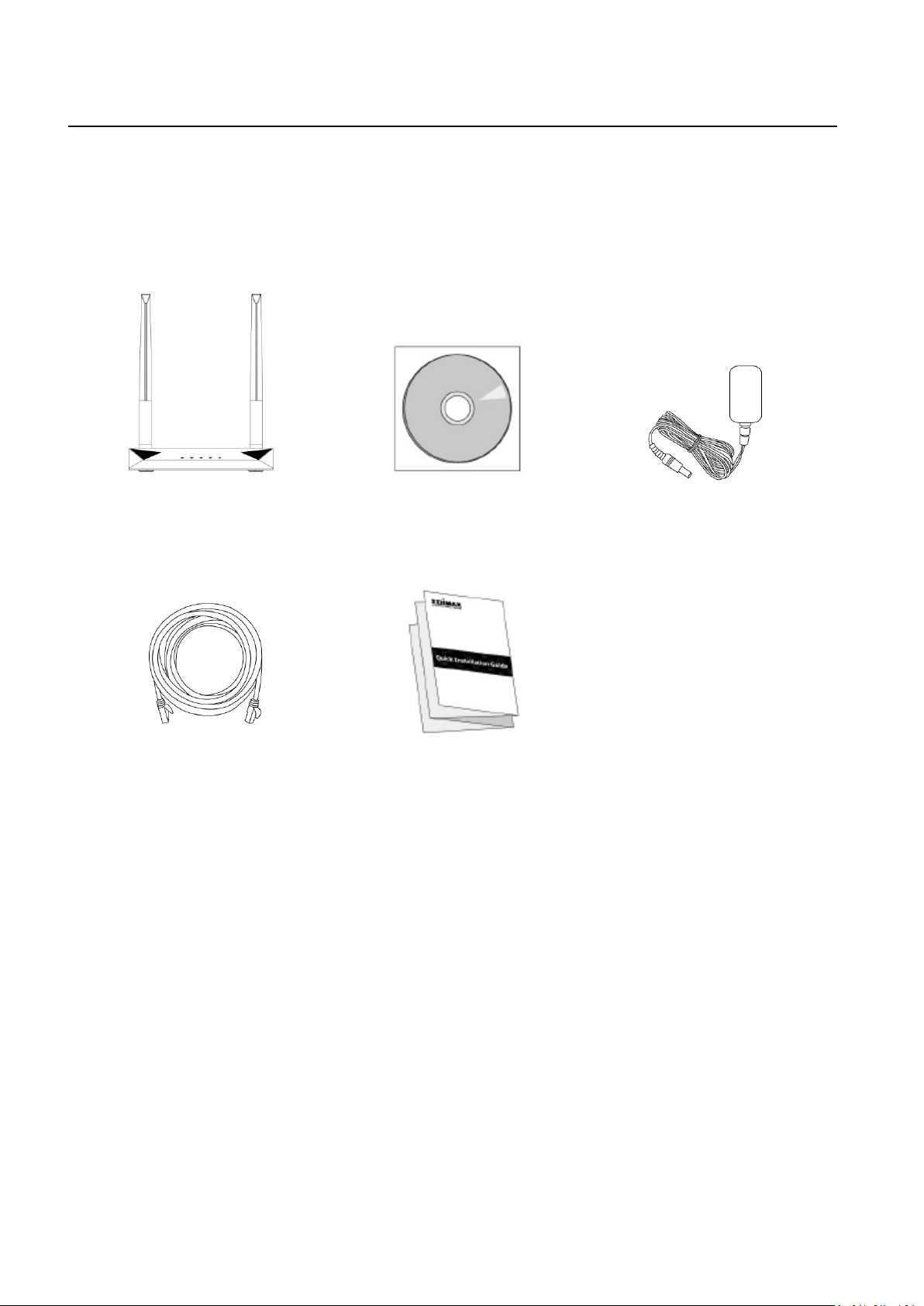
I. Product Information
BR-6428nS V5
(5dBi Antenna x 2)
Power Adapter
Ethernet Cable
Quick Installation Guide
CD-ROM
I-1. Package Contents
Before you start using this product, please check if there is anything missing in
the package, and contact your dealer to claim the missing item(s):
1
Page 5
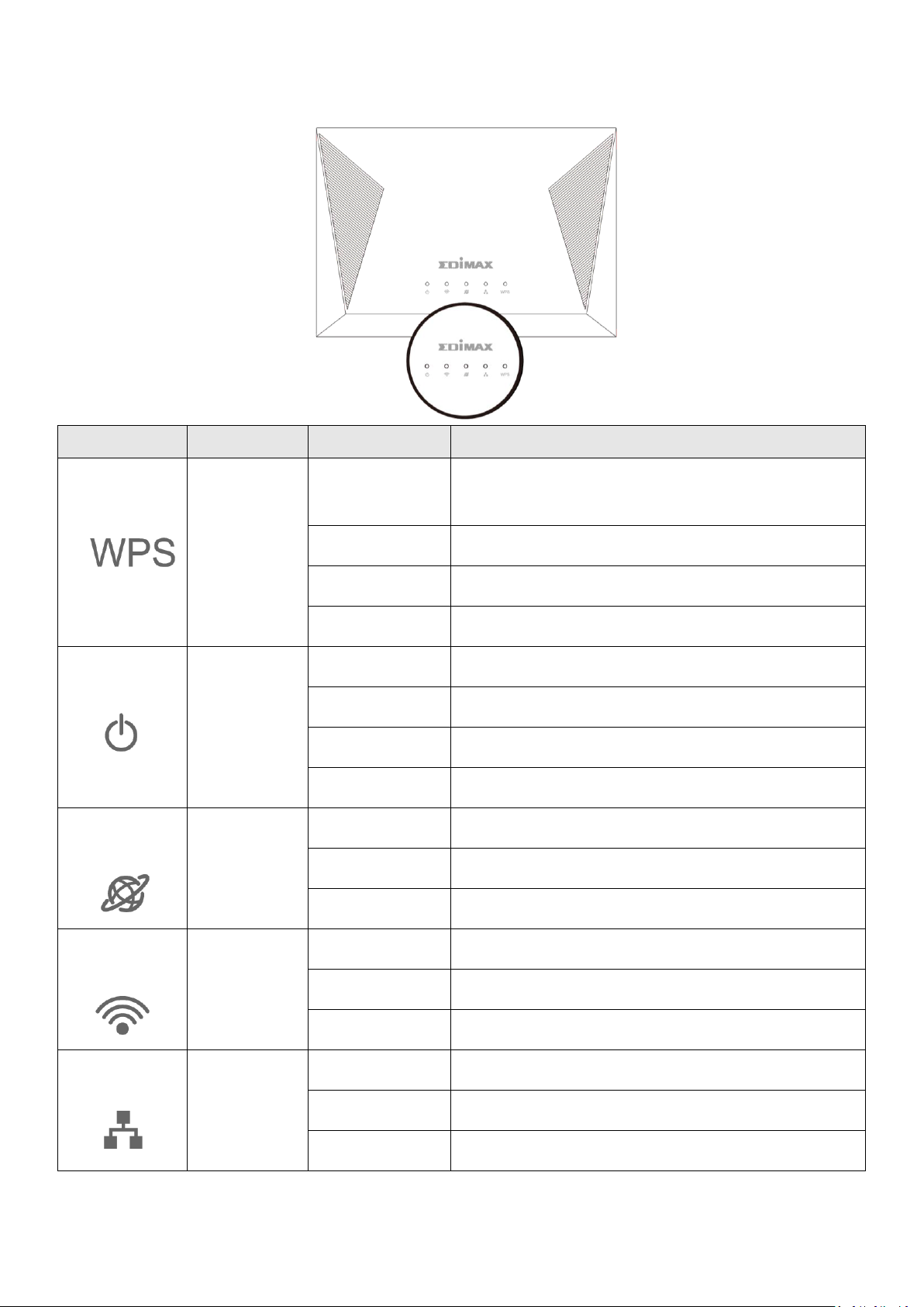
I-2. LED Status
LED
LED Colors
LED Status
Description
WPS
Green
On
Negotiation is in progress through Wi-Fi Protected
Setup.
Quick Flashing
Reset factory settings
Slow Flashing
WPS in progress
Off
WPS is disabled or connected.
PWR
Green
On
Device is on.
Quick Flashing
Reset factory settings
Slow Flashing
Firmware upgrade in process
Off
Device is off.
WAN
Green
On
WAN port connected.
Flashing
WAN activity.
Off
WAN port not connected.
WLAN
Blue
On
Wi-Fi wireless activity (transferring/receiving data).
Quick Flashing
Reset factory settings
Off
Wi-Fi not active.
LAN
Green
On
Ethernet port is connected to a network device.
Flashing
LAN activity.
Off
Ethernet port is not connected to a network device.
2
Page 6
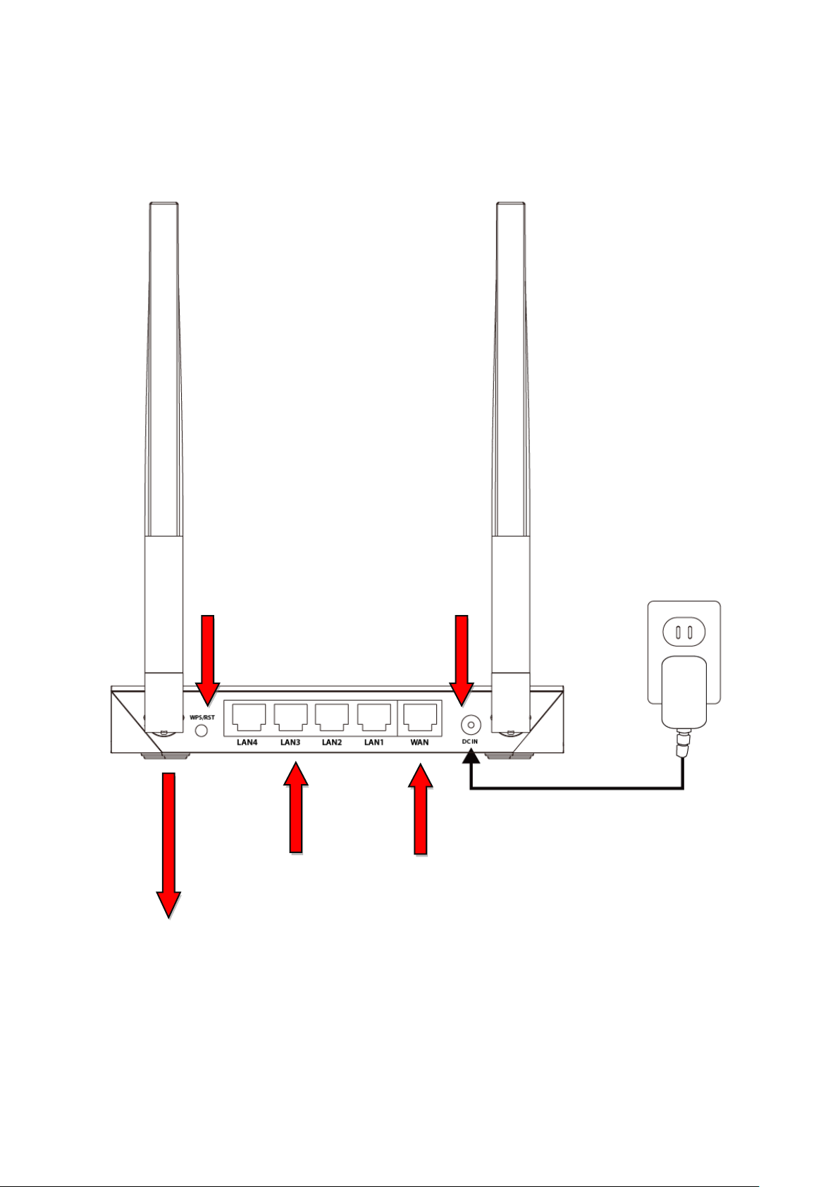
I-3. Back Panel
10/100Mbps
WAN Port
10/100 Mbps
LAN Ports 1–4
WPS/Reset Button
Power Port
BR 6428nS V5 Fixed 5dBi Antenna x 2
3
Page 7

I-4. Safety Information
In order to ensure the safe operation of the device and its users, please read
and act in accordance with the following safety instructions.
1. The device is designed for indoor use only; do not place it outdoors.
2. Do not place the device in or near hot/humid places, such as a kitchen or
bathroom.
3. Do not pull any connected cable with force; carefully disconnect it from the
BR-6428nS V5.
4. Handle the device with care. Accidental damage will void the warranty of
the device.
5. The device contains small parts which are a danger to small children under
3 years old. Please keep the device out of reach of children.
6. Do not place the device on paper, cloth, dust, corrosive liquids or other
flammable materials. The device may become hot during use.
7. There are no user-serviceable parts inside the device. If you experience
problems with the device, please contact your dealer of purchase and ask
for help.
8. The device is an electrical device and as such, if it becomes wet for any
reason, do not attempt to touch it without switching the power supply off.
Contact an experienced electrical technician for further help.
9. Plug this product directly into a wall socket (100-240V~, 50/60Hz). Do not
use an extension cord between this product and the AC power source.
10.The Operating temperature is 0℃~40℃ (32℉~104℉). The Storage
temperature is -40℃~70℃ (-40℉~158℉).
4
Page 8
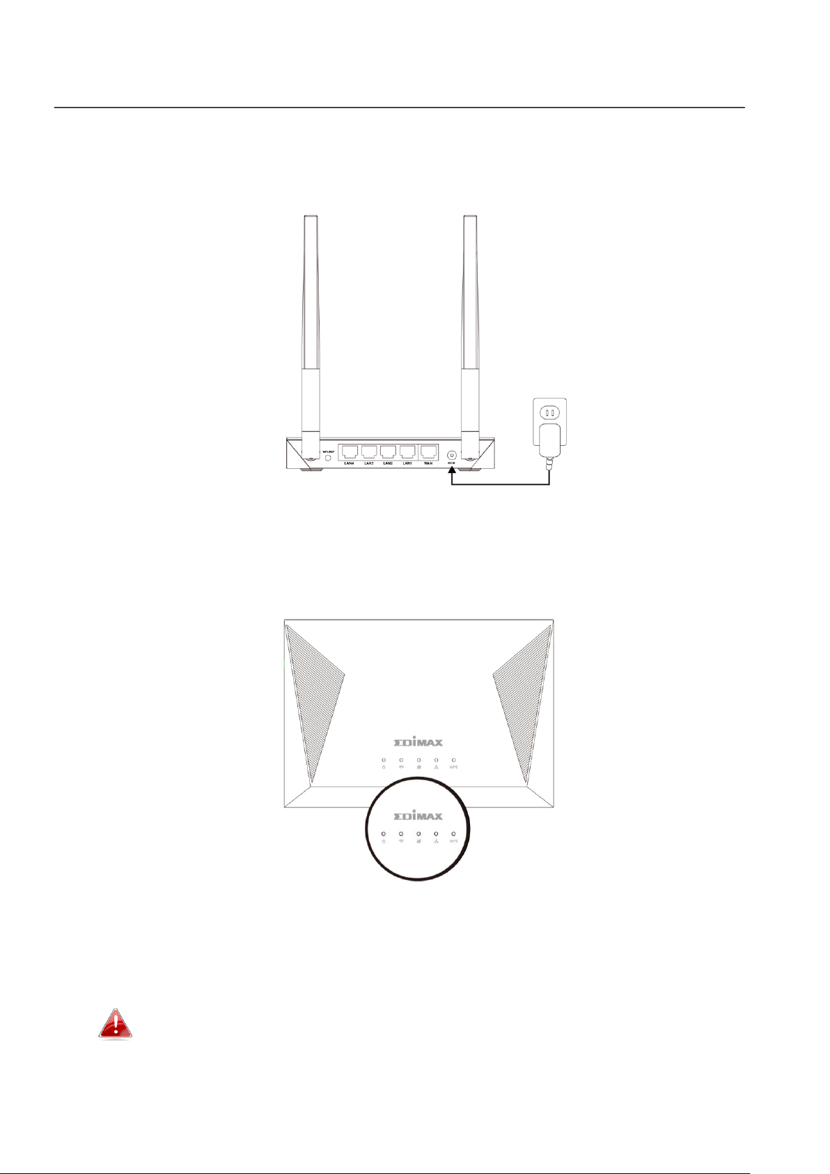
II. Installation
1. Plug the included power adapter into the device’s 5V DC power port and
the other end into an electrical socket.
2. Ensure that the power LED is lit. If not, the device is not properly
connected.
3. Use a Wi-Fi device (e.g. computer, tablet, smartphone) to search for a Wi-Fi
network with the SSID “edimax.setup” and connect to it.
iOS 4 or Android 4 and above are required for setup on a
smartphone or tablet.
5
Page 9
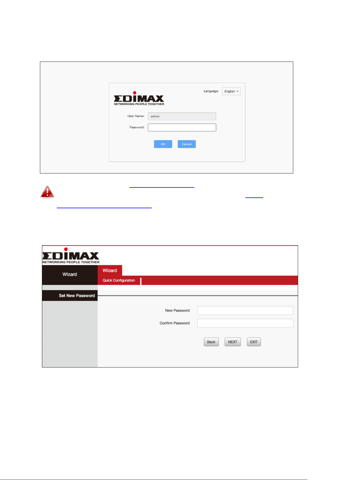
4. Open a web browser and if you do not automatically arrive at the log in
screen shown below, enter the URL http://192.168.2.1 and begin the setup
process.
If you cannot access http://192.168.2.1, please make sure your
computer is set to use a dynamic IP address. Refer to IV-1.
Configuring your IP address for more information.
5. Enter new password, confirmed and click “NEXT’ to continue.
6
Page 10
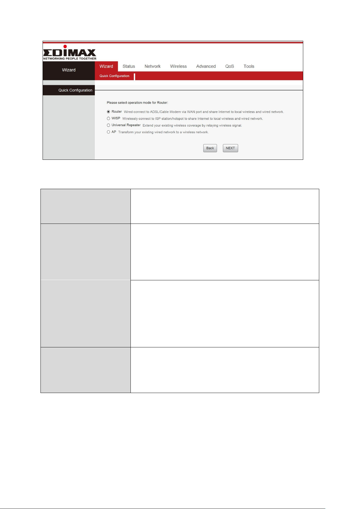
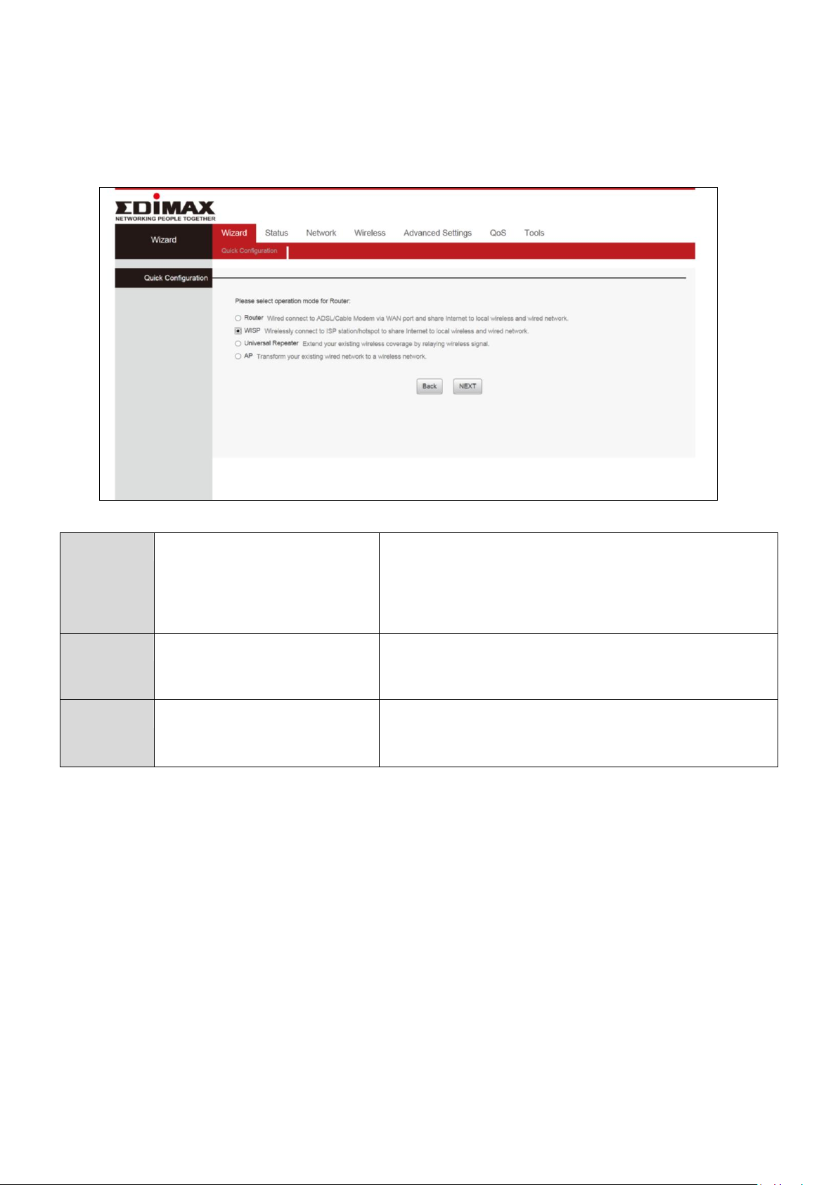
6. Select the mode for your BR-6428nS V5 and click “NEXT” to continue.
Wi-Fi Router
The device connects to your modem and
enables Internet (wireless and Ethernet)
access on your network devices.
WISP Mode
The device connects wirelessly to your
Wireless Internet Service Provider and
provides 2.4GHz and/or 5GHz Internet
(wireless and Ethernet) access for your
network devices.
Universal Repeater
The device will act as a wireless range
extender that will help you to extend your
Wi-Fi network. The device acts as a client and
AP at the same time. It its client function to
connect to a root AP, and uses its AP function
to service wireless clients within its coverage.
Access Point
The device connects to an existing router via
Ethernet cable and provides Internet (wireless
and Ethernet) access for your network
devices.
Follow the appropriate instructions for your operating mode:
7
Page 11
II-1. Wi-Fi Router Mode
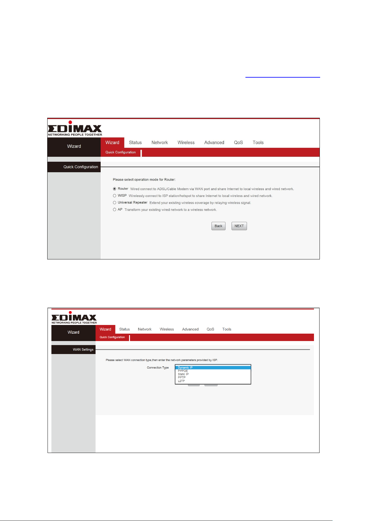
1. Connect the blue WAN port of your BR-6428nS V5 to the LAN port of your
modem using an Ethernet cable, and then log on to http://192.168.2.1.
2. Select “Router” mode and click “NEXT”.
3. You can select “Dynamic IP”, “Static IP”, and “PPPOE” mode.
8
Page 12
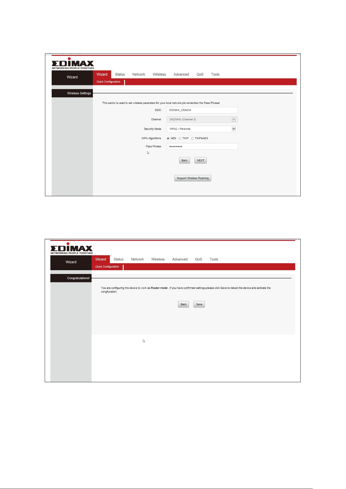
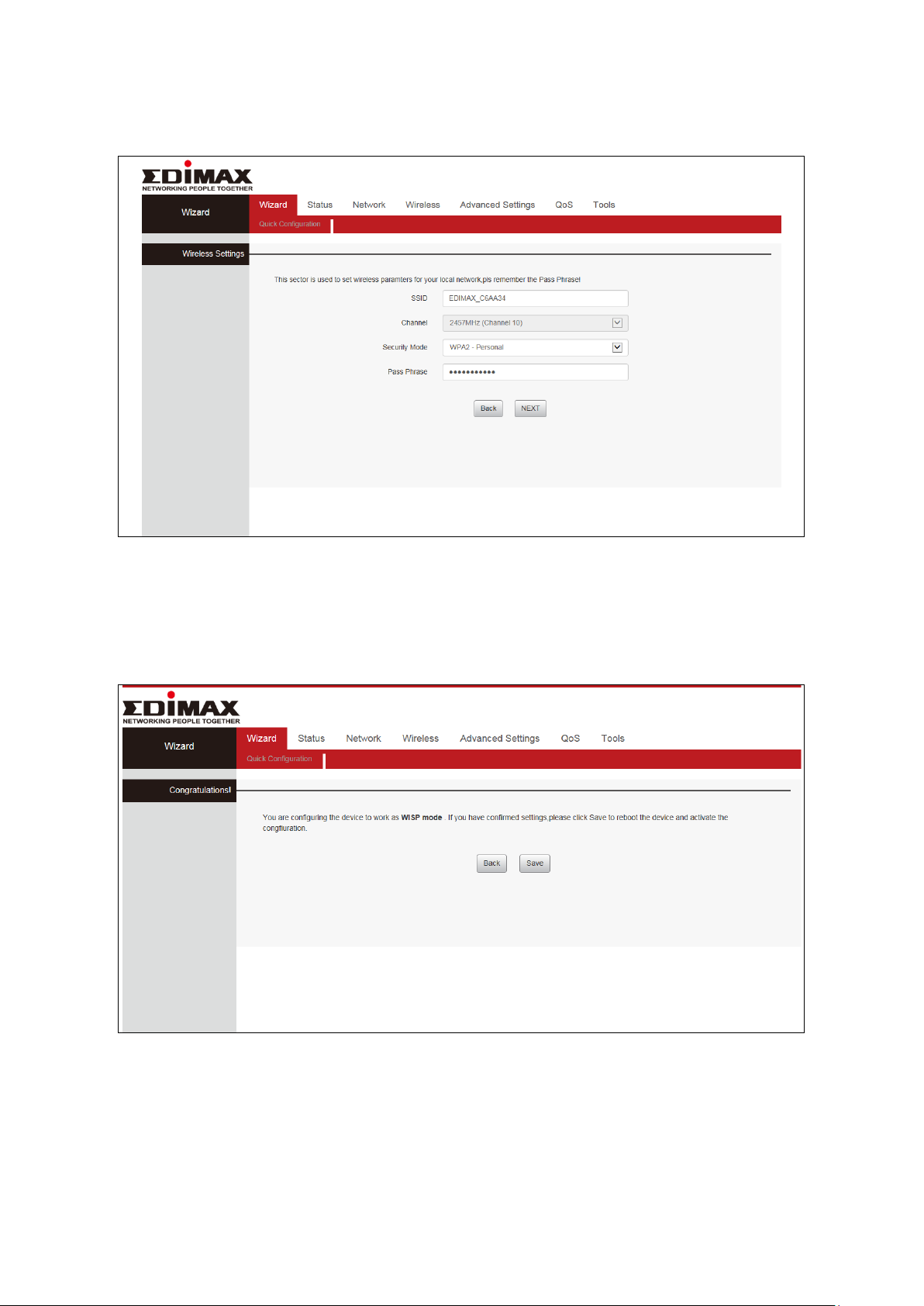
4. Confirm the configuration details for your wireless network, then click
“NEXT” to continue.
5. Please click “Save” to reboot the device and activate the configuration.
9
Page 13

6. Please wait a moment until the BR-6428nS V5 is ready.
7. When the setup is complete. Please close the browser window.
8. The BR-6428nS V5 is working and ready for use. You can now connect to
the device’s new SSID. Please refer to IV-2. Connecting to a Wi-Fi network
if you require more guidance.
10
Page 14

II-2. WISP Mode
1. Please ensure your BR-6478nS V5 is within Wi-Fi range of your WISP
network. Log on to http://192.168.2.1 to configure your device.
2. Select WISP mode and click “NEXT”.
3. Click “Site Survey” to scan the wireless signals and connect to desired
device.
11
Page 15
4. A summary of your wireless configuration will be displayed, as shown
below. Check that all of the details are correct and then click “NEXT” to
proceed.
5. Please click “Save” to reboot the device and activate the configuration.
12
Page 16

6. Please wait a moment until the BR-6428nS V5 is ready.
7. When the setup is complete, please close the browser window.
8. The BR-6428nS V5 is working and ready for use. You can now connect to
the device’s new SSID. Please refer to IV-2. Connecting to a Wi-Fi network
if you require more guidance.
13
Page 17
II-3. Universal Repeater Mode
1. Please ensure your BR-6428nS V5 is within Wi-Fi range of your existing
wireless router. Log on to http://192.168.2.1 to configure your device.
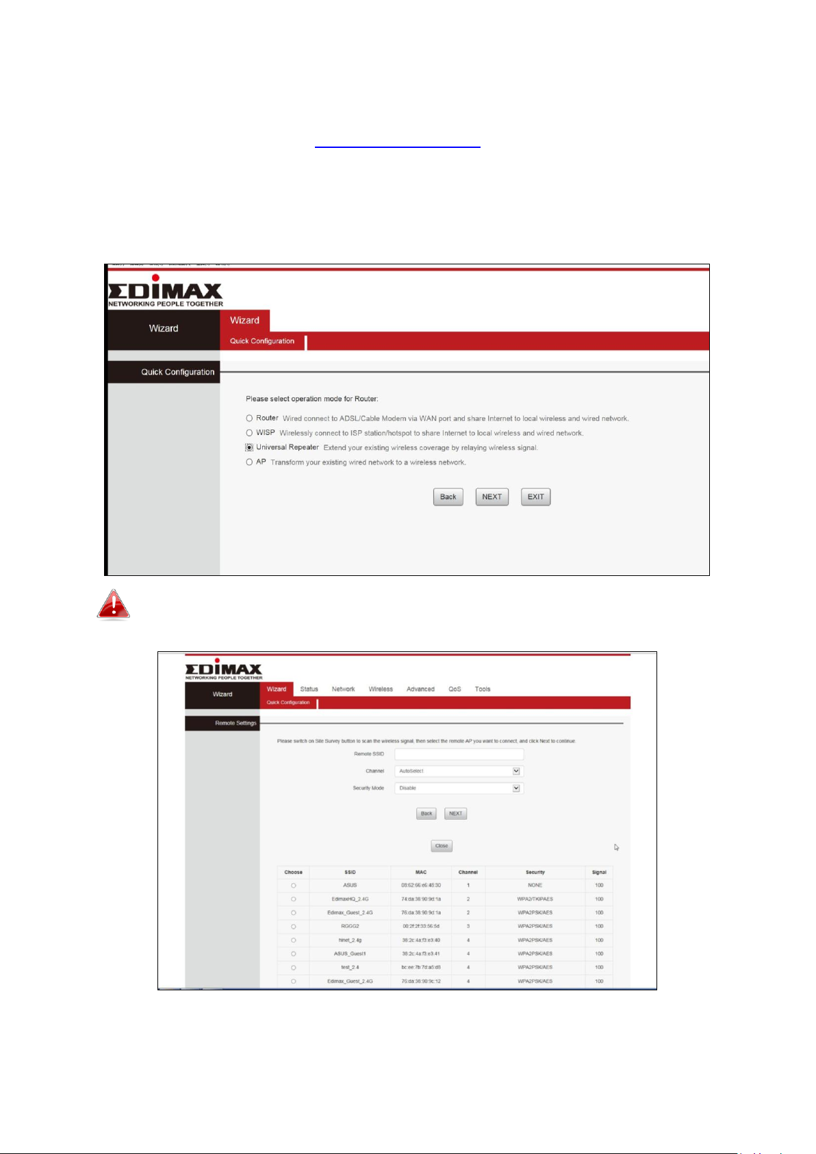
2. Select Repeater Mode and click “NEXT”.
If the Wi-Fi network you wish to connect to does not appear, try
clicking “Refresh”.
14
Page 18
3. The device will search for nearby wireless networks to connect to. If you
cannot find the access point you wish to connect to, click “Site Survey” to
refresh the list of wireless networks. Select the wireless network you wish
to connect to, and click “NEXT” to continue.
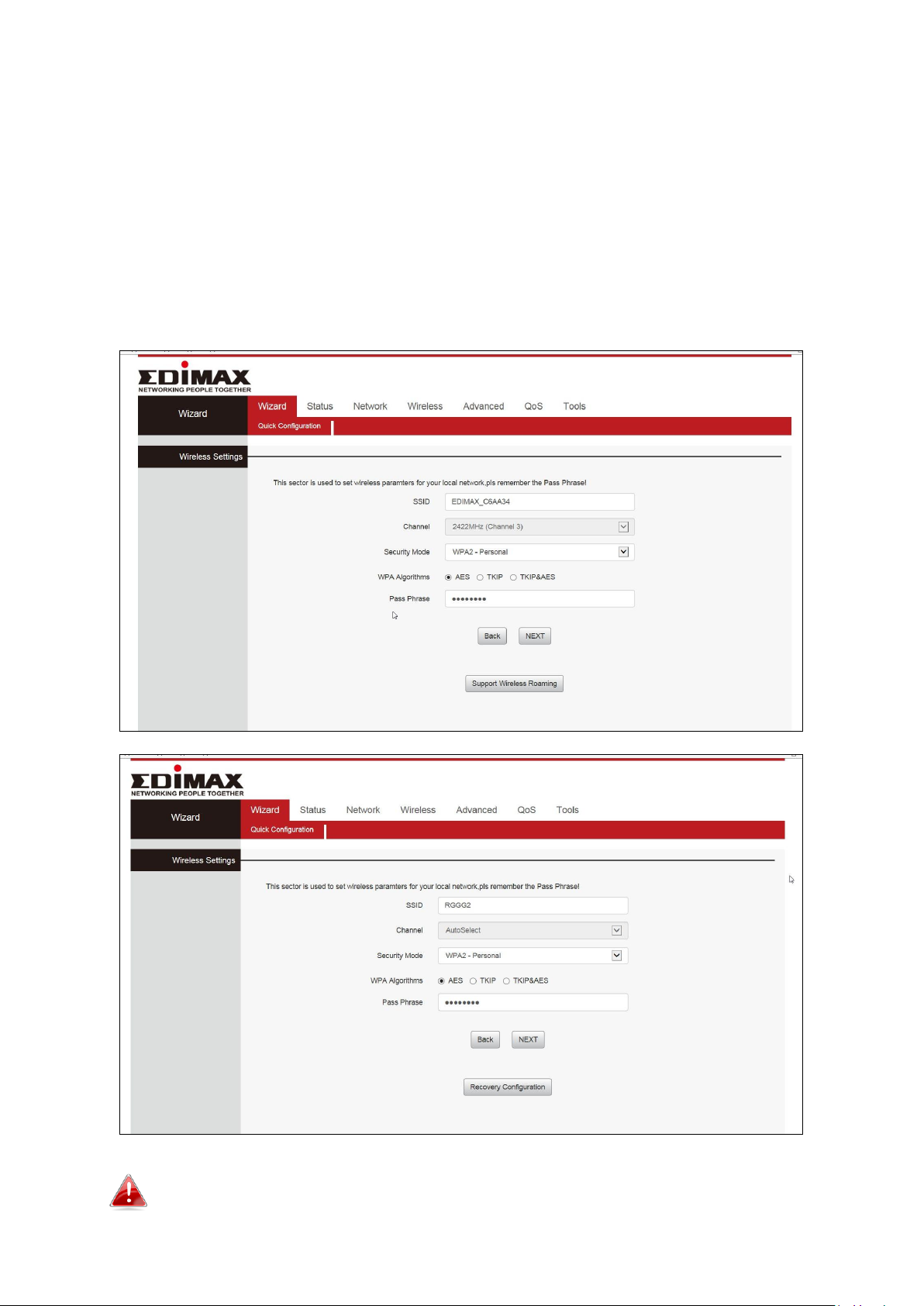
4. A summary of your wireless configuration will be displayed, as shown
below. Check that all of the details are correct and then click “NEXT” to
proceed. Click on Support Wireless Roaming to display the existing wireless
configuration.
The device will use the same wireless password/security key as
the existing wireless network.
15
Page 19
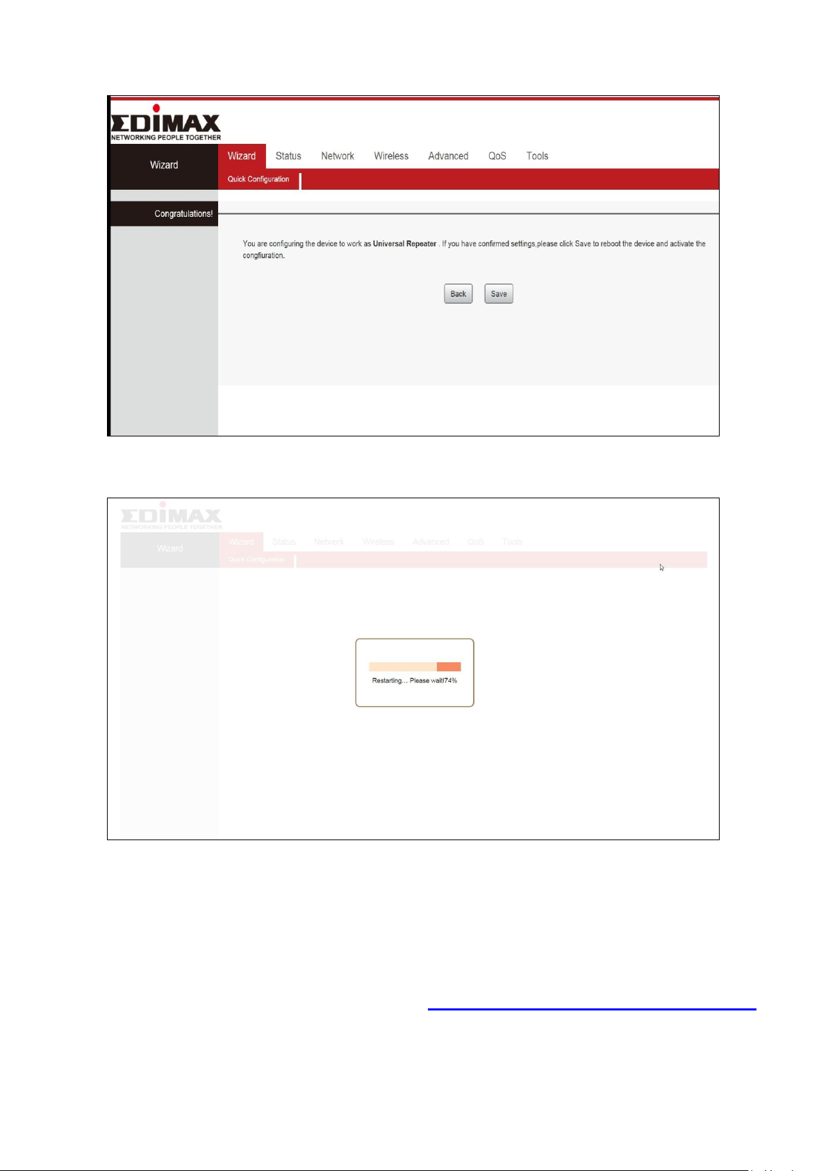
5. Please click “Save” to reboot the device and activate the configuration.
6. Please wait a moment until the BR-6428nS V5 is ready.
7. When the setup is complete. Please close the browser window.
8. The BR-6428nS V5 is working and ready for use. You can now connect to
the device’s new SSID. Please refer to IV-2. Connecting to a Wi-Fi network
if you require more guidance.
16
Page 20
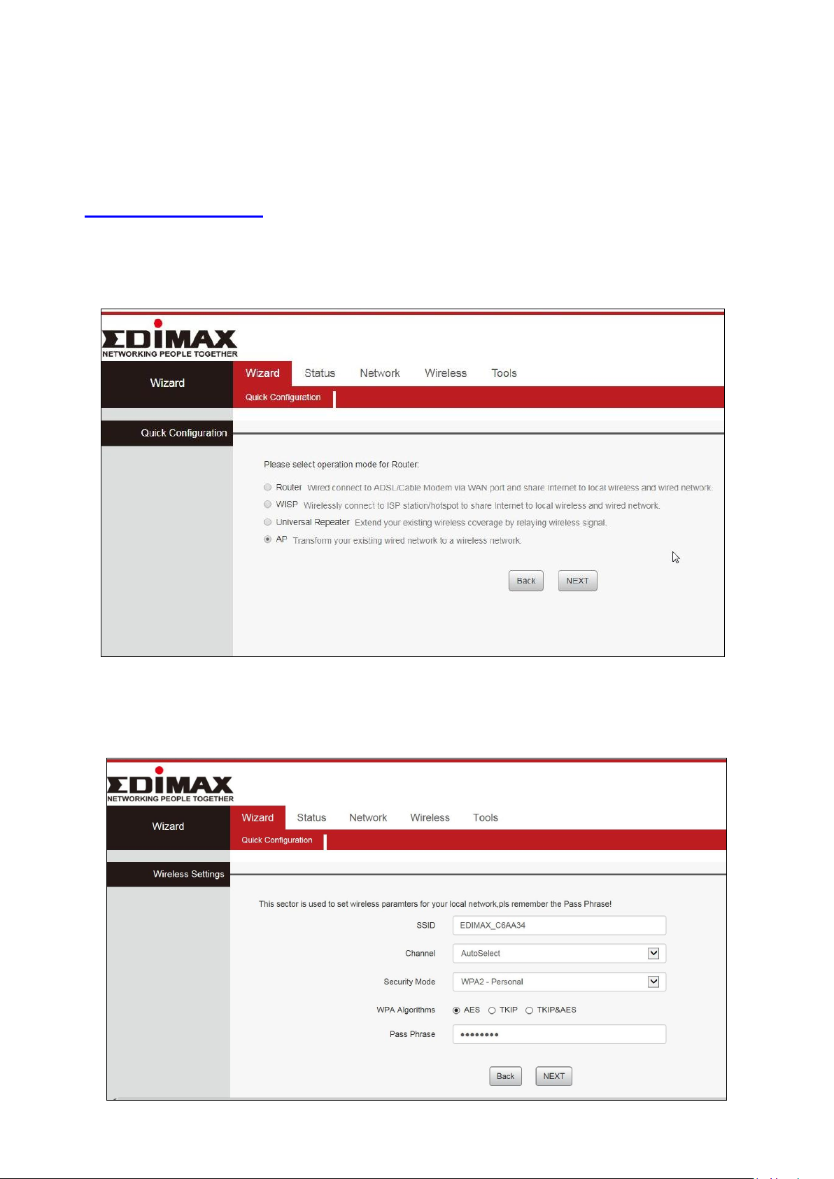
II-4. Access Point Mode
1. Connect the yellow LAN port of your BR-6428nS V5 to the LAN port of
your existing router using an Ethernet cable, and then log on to
http://192.168.2.1.
2. Select “AP” mode and click “NEXT”.
3. Confirm the configuration details for your wireless network, then click
“NEXT” to continue.
17
Page 21
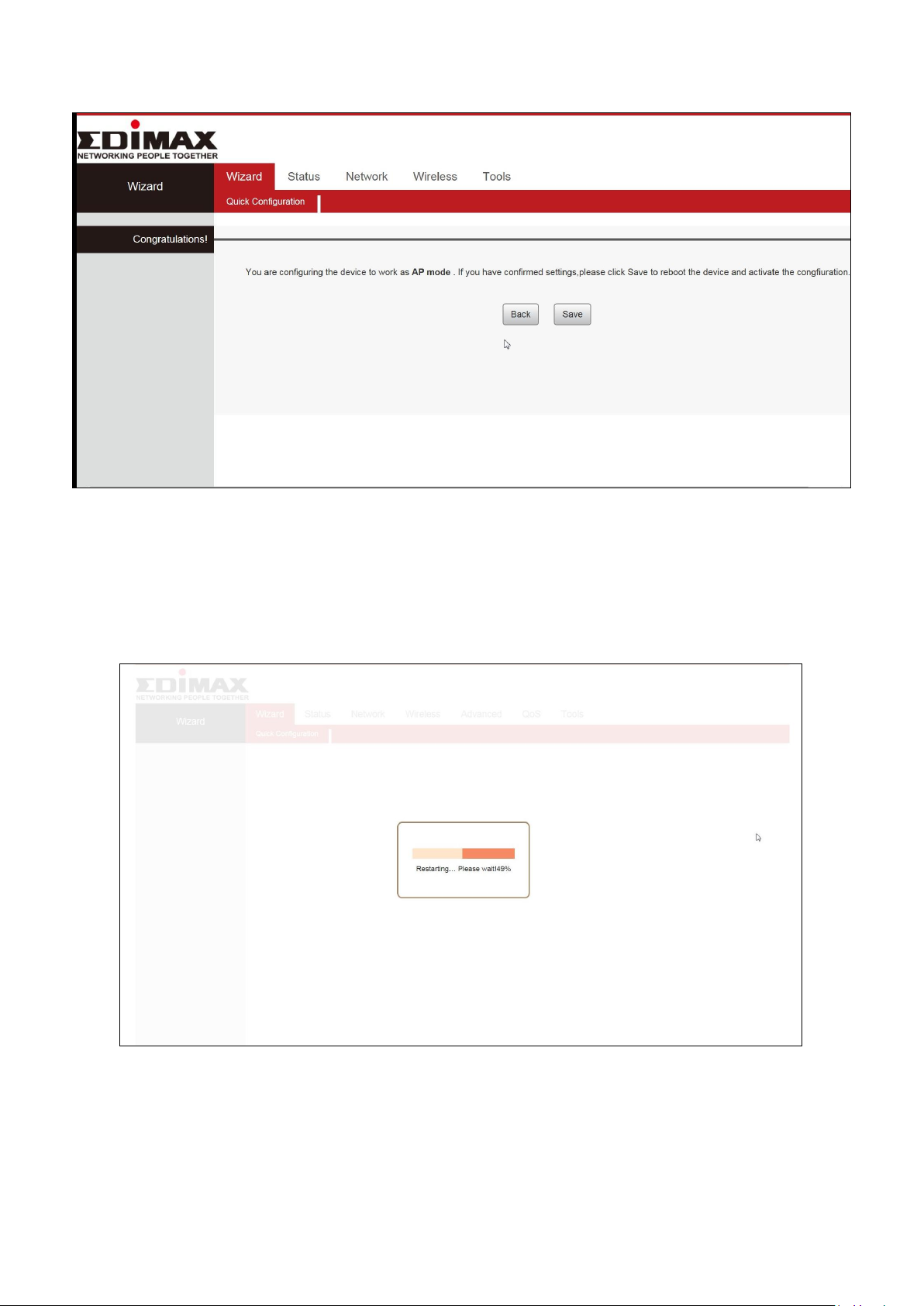
4. Please click “Save” to reboot the device and activate the configuration.
5. Please wait a moment until the BR-6428nS V5 is ready.
18
Page 22

6. When the setup is complete. Please close the browser window.
7. The BR-6428nS V5 is working and ready for use. You can now connect to
the device’s new SSID. Please refer to IV-2. Connecting to a Wi-Fi network
if you require more guidance.
19
Page 23
II-5. WPS Setup
If your wireless device supports WPS (Wi-Fi Protected Setup) then you can use this
method to connect to the BR-6428nS V5’s Wi-Fi network.
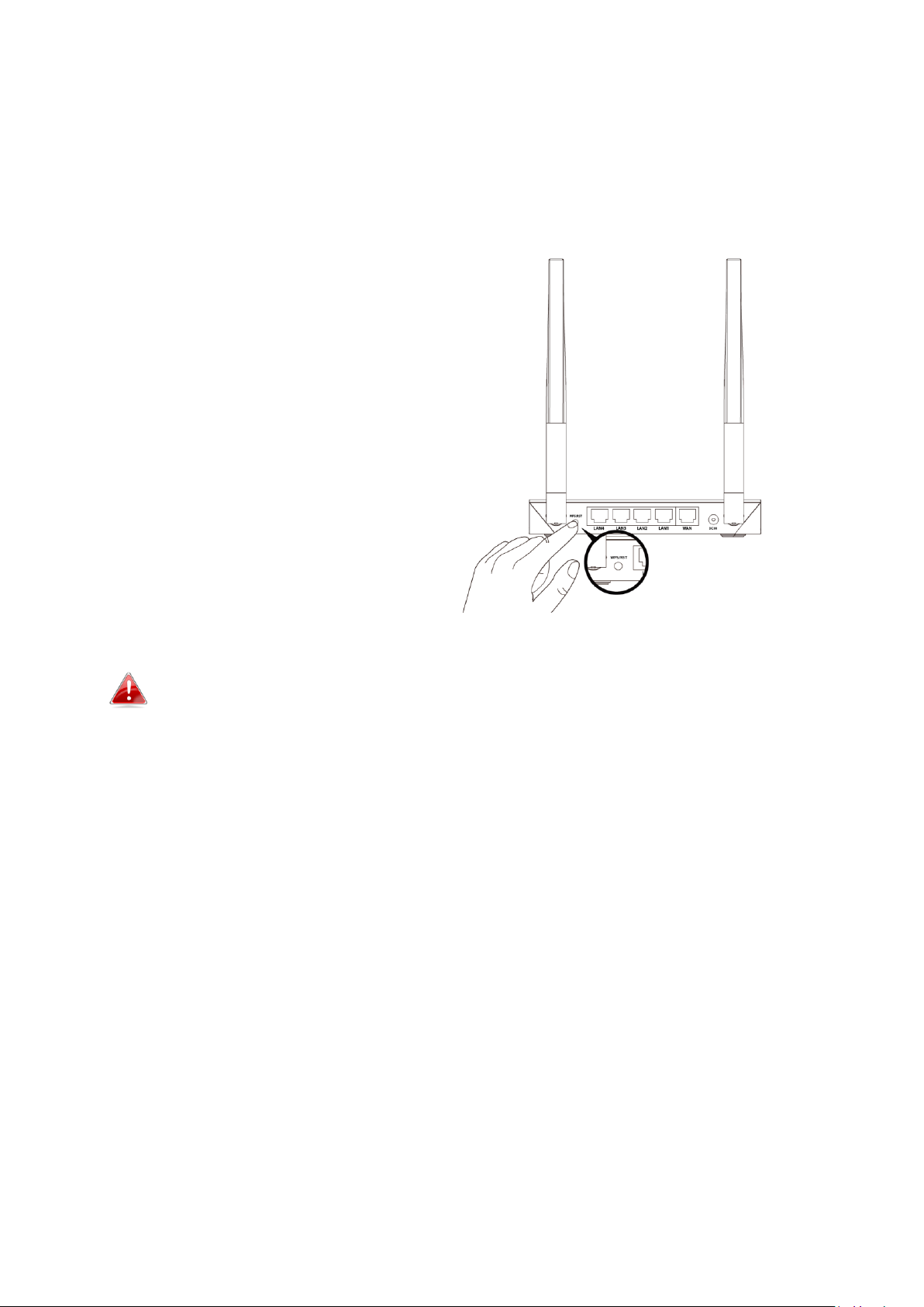
1. Press the WPS button on the
BR-6428nS V5 for 1 – 3 seconds to
activate WPS. The WPS LED will
flash for two minutes to indicate
that WPS is active.
2. Within two minutes, press the
WPS button on the wireless
device/client to activate its WPS.
3. The devices will establish a
connection. Repeat for additional
wireless devices.
Please check the instructions for your wireless device for how long
you need to hold down its WPS button to activate WPS.
II-6. Reset to Factory Default Settings
If you experience problems with your BR-6428nS V5, you can reset the device
back to its factory settings. This resets all settings back to default.
1. Press and hold the WPS/Reset button found on the back panel for at least
10 seconds, until the power LED begins to flash.
2. Release the button when the power LED is flashing.
3. Wait for the BR-6428nS V5 to restart. The BR-6428nS V5 is ready for setup
when the power LED displays on.
20
Page 24
III. Browser Based Configuration Interface
After you have setup the BR-6428nS V5 as detailed in II. Installation or the
included Quick Installation Guide, you can use the browser based
configuration interface to configure advanced settings.
Please ensure that your computer is set to use a dynamic IP
address. Refer to IV-1. Configuring your IP address for more
information.
III-1. Login
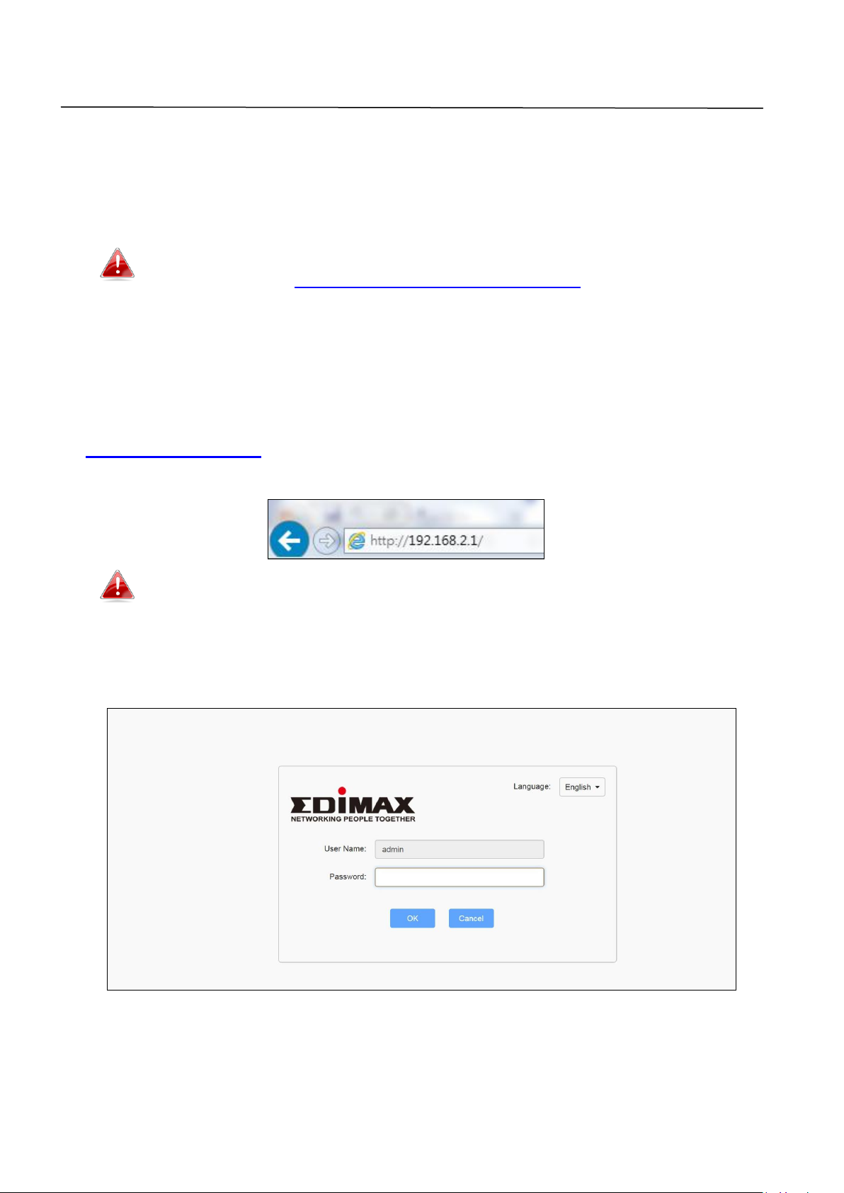
1. To access the browser based configuration interface enter
http://192.168.2.1 into the URL bar of a browser on a network device
connected to the same Wi-Fi network as the BR-6428nS V5.
If you can not access http://192.168.2.1, connect the device to a
computer using an Ethernet cable and try again.
2. You will be prompted for a username and password. The default
username is “admin” and the default password is “1234”.
21
Page 25
3. Then click on the “Status” tab shown below. Use the top menu to navigate.
For more information, refer to following chapters.
22
Page 26
III-2. Main Menu
1
Top menu
User can easily Select functions in the
navigation bar menu, Select the results
displayed in the configuration section.
2
Configuration zone
Configure and view area.
3
Status
Current status
1
2
3
Main menu is consisted of three areas. User can navigate and configure
BR-6428nS V5 via the main menu.
23
Page 27
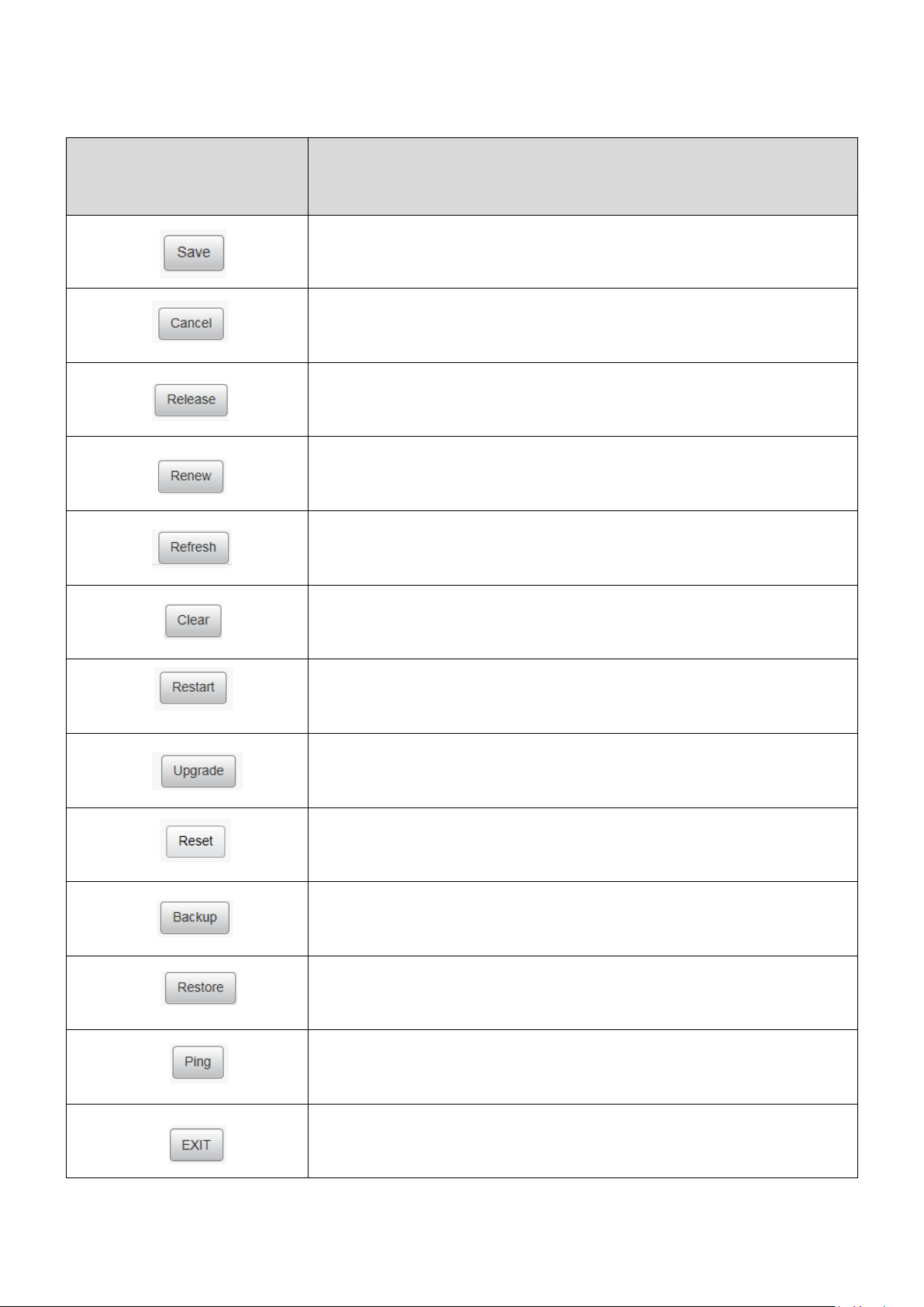
III-2-1. Commonly used web elements
Common
elements
Description
Click “Save” to save the current settings.
Click “Cancel” to cancel the changes made.
Click “Release” to release information and data.
Click “Renew” to update the information.
Click “Refresh” to update the information.
Click “Clear” to clear/erase existing information.
Click “Restart” to restart the device.
Click “Upgrade” to update the firmware.
Click “Reset” to reset the device.
Click “Backup” to back up the router's configurations.
Click “Restore” to restore the router's configurations.
Click “Ping” to send ICMP Echo Request to a specified
interface on the network and waiting for a reply.
Click “Exit” to exit the current screen.
24
Page 28
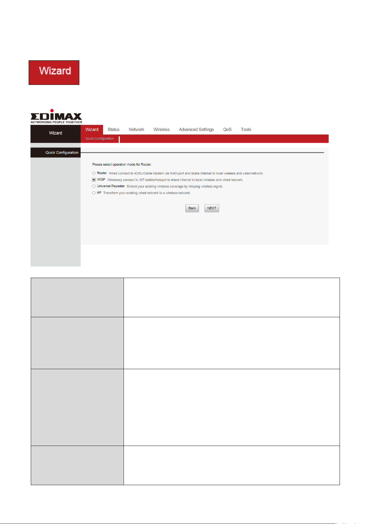
III-2-2. Setup Wizard
Wi-Fi Router
The device connects to your modem and enables
Internet (wireless and Ethernet) access on your
network devices.
WISP Mode
The device connects wirelessly to your Wireless
Internet Service Provider and provides 2.4GHz
and/or 5GHz Internet (wireless and Ethernet)
access for your network devices.
Universal Repeater
The device will act as a wireless range extender
that will help you to extend your Wi-Fi network. The
device acts as a client and AP at the same time. It
its client function to connect to a root AP, and uses
its AP function to service wireless clients within its
coverage.
Access Point
The device connects to an existing router via
Ethernet cable and provides Internet (wireless and
Ethernet) access for your network devices.
You can run the setup wizard again to reconfigure the basic
settings of the device, or you can run a wizard to help you
switch the device to a different operating mode. Select
“Wizard” then click on “Quick Configuration” to begin.
25
Page 29
Switch to Router/AP/Universal Repeater/WISP
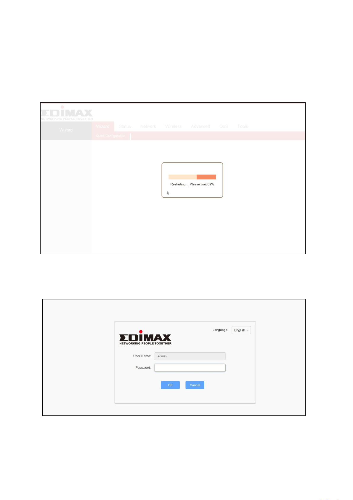
1. Follow the on-screen instructions to reset the device back to its factory
default settings.
2. Please wait for a few moments before the device is restarted.
3. After the device has reset, the log in page will appear. Enter the log in
information to proceed.
4. Follow the on-screen wizard to setup your device in a different mode.
26
Page 30
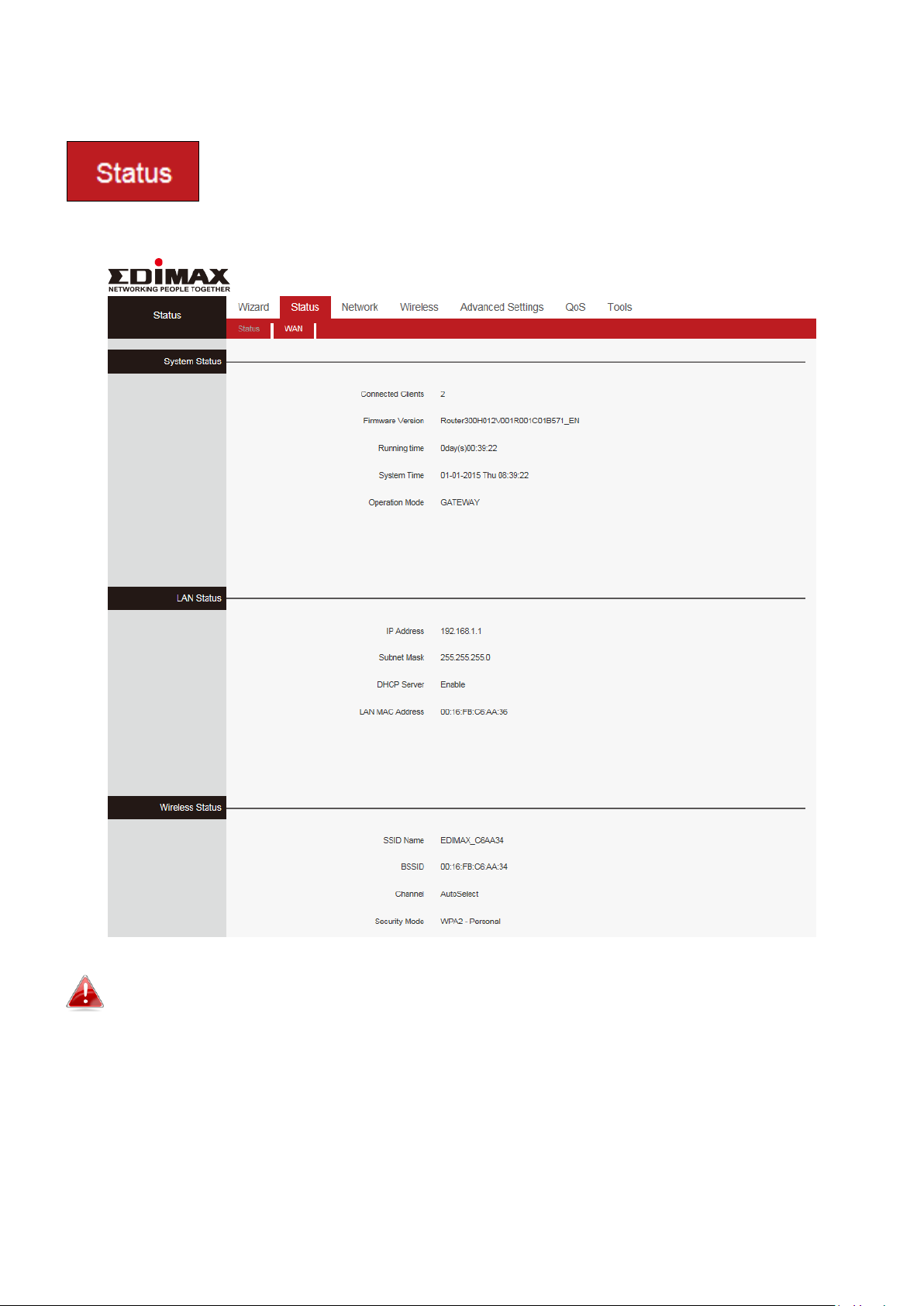
III-2-3. Status
The “Status” page displays basic system information about the
device, arranged into four categories: System, LAN, Wireless
and WAN.
Screenshots displayed are examples. The information shown on your screen will
vary depending on your configuration.
27
Page 31

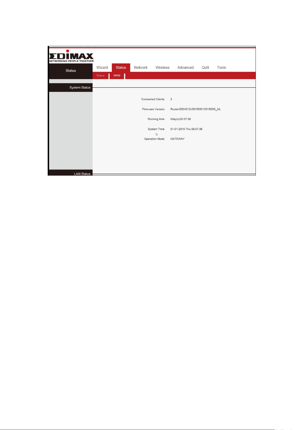
III-2-3-1. System Status
Connected Clients
Displays the number of DHCP clients.
Firmware Version
Firmware Version.
Running time
Displays the time duration indicating how long the
router has been up since startup. Up time is
recounted and renewed upon power off.
System Time
Current system time on this device. The device
automatically synchronizes the system time with
Internet time servers.
Operation Mode
Displays the current operation mode
This page displays Connected Clients, Firmware Version, Running Time,
System Time and operation mode.
III-2-3-2. LAN Status
28
Page 32

IP Address
The Router’s LAN IP Address (not your PC’s IP
address).
Subnet Mask
The Router’s LAN subnet mask.
DHCP Server
The status of DHCP server.
LAN MAC Address
The router’s physical address.
SSID Name
The name of Wireless.
SSID
The MAC Address of Wireless.
Channel
The Channel of Wireless.
Security Mode
Encryption schemes.
III-2-3-3. Wireless Status
29
Page 33

III-2-3-4. WAN Status
Connection Type
It displays the current access mode of WAN port.
Connection Status
The network connection status.
WAN MAC Address
MAC address of your ISP's router to see.
WAN IP
IP address obtained from ISP.
Subnet Mask
Obtained from ISP.
Gateway
Obtained from ISP.
Primary DNS Server
Obtained from ISP.
Secondary DNS Server
Obtained from ISP.
Connection Duration
Access method for dynamic IP or PPPOE server and
router and ISP connection is properly timed.
III-3. Network
Click “Network” to enter the Network setup web page, in this page you can
set “WAN”, “WAN Speed”, “MAC Cloning”, “DNS Settings”, “WAN Security”,
“LAN Settings”, “DHCP” and “Address Reservation”.
30
Page 34

III-3-1. WAN Settings
Connection Type
It displays the routers mode.
MTU
Maximum Transmission Unit. It is the size of the
largest data packet that can be sent over the
network. The default value is 1500.
WAN Settings configure the Internet access and support Static IP mode,
Dynamic IP (DHCP), PPPOE, L2TP and PPTP.
III-3-1-1. WAN Settings- Dynamic IP
Click “Network”, select “WAN”, then elect Connection Type to “Dynamic IP”
and finally click “Save” to confirm.
31
Page 35

III-3-1-2. WAN Settings- Static IP
Connection Type
Specify a connection type:
Static IP mode, Dynamic IP (DHCP), PPPOE, L2TP or
PPTP
IP Address
Input the IP address assigned by your ISP here.
Subnet Mask
Input the subnet mask assigned by your ISP here.
Gateway
Input the default gateway assigned by your ISP
here. Some ISPs may call this “Default Route”.
Primary DNS Server
Obtained from ISP.
Secondary DNS
Server
Obtained from ISP.
MTU
Enter the maximum transmission unit (MTU) value
of your network connection. The default value is
1400.
Click “Network”, Select “WAN”, Select Connection Type “Static IP”. Then enter
IP, Subnet Mask, Gateway, MTU and DNS. Finally, click “Save” to confirm.
32
Page 36

III-3-1-3. WAN Settings- PPPOE
Connection Type
Specify a connection type:
Static IP mode, Dynamic IP (DHCP), PPPOE, L2TP or
PPTP
User Name
Input the user name assigned by your ISP here.
Password
Input the password assigned by your ISP here.
MTU
Enter the maximum transmission unit (MTU) value
of your network connection. The default value is
1492.
Service Name
Enter the host name of your computer here If
required.
Click “Network”, select “WAN”, then select Connection Type “PPPOE”. Enter
the ISP login User Name and the ISP login Password. Finally, click “Save” to
confirm. To confirm the configuration details, click “System Status” > “WAN
Status”.
33
Page 37

III-3-1-4. WAN Settings- PPTP
PPTP Server
Input the PPTP gateway assigned by your ISP here.
User Name
Input the user name assigned by your ISP here.
Password
Input the password assigned by your ISP here.
MTU
Enter the maximum transmission unit (MTU) value
of your network connection. The default value is
1400.
Connection Type
Specify a connection type:
Static IP mode, Dynamic IP (DHCP), PPPOE, L2TP or
PPTP
Address Mode
Specify the dynamic or static address mode
MPPE
MPPE provides data security for the PPTP
connection that is between the VPN client and the
VPN server.
Select “PPTP” if your ISP is providing you Internet access via PPTP
(Point-to-Point Tunneling Protocol).
Click “Network”, select “WAN”, then select Connection Type “PPTP”. Enter the
PPTP Server, User name, Password, Address Mode and MTU. Finally, click
“Save” to confirm.
34
Page 38

III-3-1-5. WAN Settings- L2TP
Connection Type
Specify a connection type:
Static IP mode, Dynamic IP (DHCP), PPPOE, L2TP or
PPTP
L2TP Server
Input the L2TP gateway assigned by your ISP here.
UserName
Input the user name assigned by your ISP here.
Password
Input the password assigned by your ISP here.
Address Mode
Specify the dynamic or static address mode
MTU
Enter the maximum transmission unit (MTU) value
of your network connection. The default value is
1400.
Select “L2TP” if your ISP is providing you Internet access via L2TP (Layer 2
Tunneling Protocol).
Click “Network”, select “WAN”, then select Connection Type “L2TP”. Enter the
L2TP Server, User name, Password, Address Mode and MTU. Finally, click
“Save” to confirm.
35
Page 39

III-3-2. WAN Speed
Speed Mode
Set the value to match with the status. Modes
include Auto, 10M half-duplex, 10M full-duplex,
100M half-duplex, 100M full-duplex
Click “Network”, select “WAN Speed”, then select Speed Mode type. Finally,
click “Save” to confirm.
III-3-3. MAC Cloning
Some ISPs (Internet Service Providers) require end-user's MAC address to
access their network. This feature copies your current PC's MAC address to
the router.
Click “Network”, then “MAC Cloning”. You can set this page from three
methods:
1. To Restore to Factory Default MAC
a.Click “Restore to factory Default MAC”
b.Click Save to save your settings.
2. To clone the MAC address of the computer that you are now using to the
router
a.Click Clone My PC’s MAC Address.
b.Click Save to save your settings.
36
Page 40

3.To manually enter the MAC address allowed by your ISP:
MAC Address
The computer or broadband modem authorized by
your ISP.
Restore to Factory
Default MAC
Reset the router’s WAN MAC to factory default.
Clone MAC
copies the MAC address of the computer that you
are now using to the router
a.Enter the MAC address allowed by your ISP.
b.Click Save to save your settings.
III-3-4. DNS Settings
37
Page 41

SPI firewall
Enable or disable the stateful packet inspection (SPI)
firewall.
VPN
Supports enable/disable PPTP passthrough, L2TP
passthrough and IPSec Passthrough
ALG
Application Layer Gateway (ALG) is a network
security gateway which supports specific network
applications such as gaming and instant messaging.
ALG enables these applications to communicate with
their server.
Supports enable/disable FTP ALG and TFTP ALG
DNS Settings
Enable/Disable DNS Settings
III-3-5. WAN Security
38
Page 42

III-3-6. LAN Settings
MAC Address
Displays the Router’s LAN MAC address.
IP Address
Displays the Router’s LAN IP address.
Subnet Mask
Displays the Router’s LAN subnet mask.
This page is to configure the basic parameters for LAN ports. This IP address is
to be used to access the device’s settings through a web browser. Be sure to
make a note of any changes you apply to this page.
Click “Network”, select “LAN Settings”. Enter IP Address, Subnet Mask. Then
click “Save” and wait for the router reboot automatically.
The router's LAN IP address and WAN IP address cannot be on the same IP
segment. If not, the router will not be able to access Internet.
Be sure to make a note of any changes you apply to this page. If you change
the LAN IP address of the router, you have to open a new connection to the
new IP address and log in again. Also, you have to set the default gateway
addresses of all LAN PCs to this new IP address.
39
Page 43

III-3-7. DHCP
DHCP Server
Select whether enable or disable the DHCP server
feature.
Start IP Address
Part of the same IP address subnet as the router’s
LAN IP address.
End IP Address
Part of the same IP address subnet as the router’s
LAN IP address.
Lease Time
The length of the IP address lease before it is
refreshed.
DHCP (Dynamic Host Configuration Protocol) is a protocol used to provide
quick, automatic, and central management for the distribution of IP
addresses within a network.
DHCP is also used to configure the proper subnet mask, default gateway,
and DNS server information on the device. Click “Network” and select
“DHCP”.
40
Page 44

III-3-8. Address Reservation
This function allows you to learn whether there are unauthorized accesses by
viewing the client list. Also, you can specify a reserved IP address for a PC in
the LAN. That PC will always receive the same IP address each time when it
accesses the DHCP server. Reserved IP addresses could be assigned to servers
that require permanent IP settings.
Click “Network” and select “Address Reservation”. Enter the IP Address and
MAC Address. Click “Add” add to the DHCP list, click “Save” to save your
settings, then click “Refresh” to update the related DHCP client information.
III-4. Wireless
The “Wireless” menu allows you to configure SSID and security settings for
your Wi-Fi network along with a guest Wi-Fi network. Click “Wireless” to enter
the configure page , here you can configure “Wireless Settings”, “Wireless
Security”, “Multi SSID”, “WPS Settings”, “Wireless MAC Filtering”, “Wireless
Statistics”.
III-4-1. Wireless Settings
Click “Wireless”, select “Basic Settings”. Then enable Wireless, select Network
Mode. Enter SSID name, select “Channel” and select “Channel BandWidth”.
41
Page 45

Wireless
Enable/Disable wireless connection
Network Mode
Select a correct mode according to your wireless
clients.
11b: This network mode delivers wireless speed
up to 11Mbps and is only compatible with 11b
wireless clients.
11g: This network mode delivers wireless speed
up to 54Mbps and is only compatible with 11g
wireless clients.
11b/g mixed: This network mode delivers
wireless speed up to 54Mbps and is compatible
with 11b/g wireless clients.
11b/g/n mixed: This network mode delivers
wireless speed up to 300Mbps and is compatible
with 11b/g/n wireless clients
SSID
The unique name of the wireless network and can
be modified
Broadcast (SSID)
Select “Enable” to enable the router’ SSID to be
scanned by wireless devices. The default is enabled.
If you disable it, the wireless devices must know the
SSID for communication.
42
Page 46

BSSID
The MAC address of the device's wireless interface.
Channel
The currently used channel by the router. Select an
effective channel of the wireless network. The
default is AutoSelect.
Channel Bandwidth
Select an appropriate channel bandwidth to
enhance the wireless performance. Select 20/40M
when the network has 11b/g/n to promote its
throughput.
Extension Channel
The extension channel can either be "above" or
"below" the control channel, if you feel you are not
getting appropriate throughput, you may check
specific extension channels for improvements.
Tx Power
Set the power output of the wireless radio. You may
not require 100% output power. Setting a lower
power output can enhance security since potentially
malicious/unknown users in distant areas will not be
able to access your signal.
WMM Capable
WMM (Wi-Fi Multimedia) technology can improve
the performance of certain network applications,
such as audio/video streaming, network telephony
(VoIP) and others. When WMM is enabled, the
device will prioritize different kinds of data and give
higher priority to applications which require instant
responses for better performance.
APSD Capable
Automatic Power Save Delivery (APSD)
enable/Disable the use of auto power-saved service
It is advisable to only change the SSID (name of the network) and channel
and leave other items unchanged.
III-4-2. Wireless Security
The wireless security function can prevent others from connecting to your
wireless network and using the network resources without your consent.
Meanwhile, you can also block illegal users from intercepting or intruding
your wireless network. Click “Wireless”, Select “Wireless Security” and choose
security modes, Disable, WPA2 – Personal and Mixed WPA/WPA2 – Personal.
43
Page 47

Disable
Disable this function.
WPA2 – Personal
Support AES, TKIP and TKIP+AES cipher types.
Mixed WPA/WPA2 –
Personal
Both WPA-Personal and WPA2-Personal secured
wireless clients can join your wireless network.
Multi SSID
Enable/ Disable multiple wireless networks to
provide different security and VLAN groups.
III-4-3. Multi SSID
44
Page 48

III-4-4. WPS Settings
ResetOOB
The router wireless SSID and safe mode are restored
to default mode. Use WPS to reset the SSID,
Encryption and password, after the completion of
the reset, the router’s SSID is in factory default
setting and safe mode is unencrypted.
PBC
Using routers and physical or logical button on a
wireless device to connect WPS.
SSID Name
Name of SSID.
Security Mode
Displays the security mode selected.
Click “Wireless”, Select “WPS Settings”
45
Page 49

III-4-5. Wireless MAC Filtering
Filtering Rules
Select “Off” to allow all wireless clients to join
your wireless network.
Select “Allow” allow ONLY the specified wireless
clients to join your wireless network.
Select “Block” block ONLY the specified wireless
clients to join your wireless network.
This function permits or forbids specified clients to access the wireless
network based on MAC Address. If a device which is not on the list of
permitted MAC addresses attempts to connect to the BR-6428nS V5, it will be
denied.
Up to 10 wireless MAC addresses can be configured
46
Page 50

III-4-6. Wireless Statistics
No.
Number of connected wireless clients
MAC
MAC address
Bandwidth
The channel bandwidth instead of wireless
connection rate.
Refresh
Refresh the current wireless station list
This page shows the current wireless access list Click “Refresh” to update.
III-5. Advanced Settings
Click “Advanced Settings” to enter the configure page, here you can configure
“URL Filtering”, “Virtual Server”, “DMZ”, “DDNZ”, “Remote Management”,
“WAN Ping”, “Static Routing” and “Routing Table”.
III-5-1. URL Filtering
This function sets URL filtering access. If you want to enable this function,
please activate the checkbox. Select one policy from the drop-down menu and
enter a policy name in the field. Of course, you can set the access restriction
in details (e.g. the fixed IP range, URL, times and days). Note: When time is
0:0~0:0, it express 24 hours. Click “Advanced Settings”, then “URL Filtering” to
configure this function.
47
Page 51

Filering Settings
Enable/Disable the filtering rules
Policy Name
Enter a name for rule for reference/identification.
Access Policy
Up to 10 filter rules can be configured
IP Range
Enter the start and End IP address
URL String
Enter the URL or keyword to be blocked.
Time
Specify the blocking time, it is expressed in 24
hours.
Day(s)
Specify which day of the week or everyday.
URL Filter Application Example:
To prevent your home PC (192.168.1.100) from accessing “YouTube” from
8:00 to 18:00 during working days: Monday- Friday.
1. Enter a Policy Name
2. Enter the Start IP and End IP here for example:192.168.1.100
3. Enter part of or the entire domain name of the web site you wish to
restrict. Separate different domain names or domain name key words with
a comma, for example, "YouTube, Hollywood.com"
4. Select time and day
5. Click “Save” to save your settings.
48
Page 52

III-5-2. Virtual Server
You want to share resources on your PC with your friends who are not in your
LAN. But, by default, the router's firewall blocks inbound traffic from the
Internet to your computers except replies to your outbound traffic. You can
use the Port Forwarding feature to create exceptions to this rule so that your
friends can access these files from external networks.
When accessing your PC from Internet, type "protocol://xxx.xxx.xxx.xxx:port
number" into your browser’s address or location field. The protocol and port
are the ones used by the service and "xxx.xxx.xxx.xxx" is the WAN IP address
of your router. For example, a FTP server uses the ftp protocol and 21
(standard port number). Click “Advanced Settings” and select “Virtual Server”
to access this feature.
49
Page 53

ID
Number of connected devices
Start Port–End Port
Enter the start/end port number which
ranges the External ports used to set the
server or Internet applications. Here in this
example, enter 21.
To IP address
Enter the IP address of the PC where you
want to set the applications. Here in this
example, enter 192.168.1.100.
Protocol
Select the protocol (TCP/UDP/Both) for the
application.
Enable
Enable the connection
Disable
Disable the connection
If your WAN IP address is 192.168.1.100 when accessing your FTP
server from external network, your friends only need to enter
ftp:// 192.168.1.100:21 in their browsers.
50
Page 54

III-5-3. DMZ
Enable DMZ
Check/uncheck the box to enable/disable the
device’s DMZ Host function.
A Demilitarized Zone (DMZ) is an isolated area in your local network where
private IP addresses are mapped to specified internet IP addresses, allowing
unrestricted access to the private IP addresses but not to the wider local
network.
You can define a virtual DMZ host here. This is useful for example, if a
network client PC cannot run an application properly from behind an NAT
firewall, since it opens the client up to unrestricted two-way access.
III-5-4. DDNS
Dynamic DNS (DDNS) is a service which provides a hostname-to-IP service for
dynamic IP users. The changing nature of dynamic IPs means that it can be
difficult to access a service provided by a dynamic IP user; a DDNS service
though can map such dynamic IP addresses to a fixed hostname, for easier
access. The router supports several DDNS service providers, for more details
and to register for a DDNS account please visit the DDNS providers website(s),
examples of which are listed below.
51
Page 55

Enable
Check off to enable or disable DDNS Service
DDNS Service
Click the button to enable or disable the DDNS
service.
Click “Advanced Settings”, Select “DDNS”, Select “Enable”, Add “Serve
provider”. Then enter the “User name” and “Password”, enter “Domain
Name” and finally Click “Save” to confirm.
52
Page 56

Service provider
Select one from the drop-down list and click
“Sign up” for registration.
Username
Enter the username that you use to register
from the DDNS provider.
Password
Enter the password that you use to register
from the DDNS provider.
Domain name
Enter the effective registered domain name.
The following DDNS services are supported:
Port
The management port to be open to outside access.
Management
Check “Enable” to enable the remote access feature
and then enter the appropriate values.
3322 http://www.3322.org
DHS http://www.dhs.org
DynDNS http://www.dyndns.org
88 IP http://www.88ip.cn/
III-5-5. Remote Management
This section is to allow the network administrator to manage the router
remotely. If you want to access the router remotely, please select “Enable”.
For better security, configure a port number (between 1024-65535) as
remote web management interface, do not use the number of any
common service port (1-1024).
53
Page 57

Remote Web Management Application Example:
To access your router (WAN IP address: 172.16.87.160) at your home from the
PC (210.16.87.154) at your office via the port number 6060.
Set Steps:
1. Management “Enable”.
2. Enter the Port: 6060.
3. Click “Save” to save your settings.
In the PC 210.16.87.154 Type “http:// 172.16.87.160:6060” into your
browser’s address or location field and you can access the router at your
home remotely.
III-5-6. WAN Ping
The ping test is to check the status of your internet connection. When
disabling the test, the system would prevent the ping test from WAN.
54
Page 58

Select the “Advanced Settings”, Select the “WAN Ping” then select the
Enable
Check off to enable/disable and the router will not
answer ping requests from the Internet.
“Enable”.
III-5-7. Static Routing
Static routing is a method of configuring path selection of routers,
characterized by the absence of communication between routers regarding
the current topology of the network. The opposite of static routing is dynamic
routing, sometimes also referred to as adaptive routing.
You can configure static routing and manually add routes to the routing table
on this page.
55
Page 59

Destination Network
Enter the destination network’s IP address.
Subnet Mask
Enter the subnet mask of the destination network.
Gateway
Enter the default gateway of the destination
network.
Add
Add the route to the current static routing table.
Action
Specify the action taken by router
Destination IP
The IP address of the final destination. “0.0.0.0”
indicates any network segment.
Subnet Mask
The subnet mask for the specified destination.
Gateway
This is the next router on the same LAN segment as
the router to reach.
Interface
The interface between your router and the final
destination.
III-5-8. Routing Table
In this page you can view the routing table information. Click “Refresh” to
update
56
Page 60

III-6. QoS
Enable
Check the Enable box to enable the Bandwidth
Control feature.
Click “QoS” to enter the configure page. Quality of Service (QoS) is a feature
to manage Internet bandwidth efficiently. Some applications require more
bandwidth than others to function properly, and QoS allows you to ensure
that sufficient bandwidth is available. Minimum or maximum bandwidth can
be guaranteed for a specified application. Here you can configure “Bandwidth
Control”.
QoS can improve the BR-6428nS V5 performance. QoS is recommended
to optimize performance for online gaming.
III-6-1. Bandwidth Control
Bandwidth control is used to limit communication speed in the LAN. Up to 20
entries can be supported with the capability for at most 254 PCs' speed
control.
III-7. Tools
Click “Tools” enter the configure page ,here you can set “Time Settings”,
“Diagnostic Tool”, “Backup/Restore”, “Factory Default”, “Firmware Upgrade”,
“Restart”, “Password”, “System Log”.
57
Page 61

III-7-1. Time Settings
This function is to select the time zone for your location. Click “Tools”. Select
“Time Settings”. The time will synchronize with the internet automatically in
the default situation. Select “Time Zone” then click “Save” to save you
settings.
Configured time and date info will be lost if the device gets
disconnected from power supply. However, it will be updated
automatically when the device reconnects to Internet. To activate
time-based features (e.g. firewall), the time and date info shall be set
correctly first, either manually or automatically.
III-7-2. Diagnostic Tool
58
Page 62

Ping
Troubleshoots connectivity, reachability, and
name resolution to a given host or gateway.
Backup
Click this button to back up the router's
configurations.
Restore
Click this button to restore the router's
configurations.
III-7-3. Backup/Restore
Click “Tools”,select “Back/Restore”. Choose “Backup” to keep parameters.
Click “Browse” to add an file, then click “Save” to save the settings.
The default configuration file name is “RouterCfm.cfg”. Do include the
file name suffix of “.cfg” when renaming the file name to avoid
problem.
59
Page 63

III-7-4. Factory Default
Restore
Reset all configurations to the default values. It
means the device will lose all the settings you
have set. So please note down the related
settings if necessary.
Default Password: 1234
Subnet Mask:255.255.255.0
Default IP:192.168.2.1
Click “Tools”,select “Factory Default”.
If you enable this option, all current settings will be deleted and be
restored to factory default values. You will have to reconfigure
Internet connection settings and wireless settings.
Do not restore factory default settings unless the following happens:
You need to join a different network or unfortunately forget
the login password.
You cannot access Internet and your ISP or our technical
support asks you to reset the router.
60
Page 64

III-7-5. Firmware Upgrade
The upgrade page allows you to upgrade the system firmware to a more
recent version. You can download the latest firmware from the Edimax
website. After the upgrade, the system will restart.
Click “Tools”, Select “Firmware Upgrade”, click “Browse” and select the
upgrade file. Finally, click “Upgrade” and wait for the completion.
Do not switch off or disconnect the device during a firmware upgrade,
as this could damage the device. It is recommended that you use a
wired Ethernet connection for a firmware upgrade.
III-7-6. Restart
In the event that the router malfunctions or is not responding, then it is
recommended that you restart the device.
61
Page 65

III-7-7. Password
Current Password
Enter your current password.
New Password
Enter your new password.
Confirmed Password
Confirm your new password.
You can change the password used to login to the browser-based
configuration interface here. It is advised to do so for security purposes.
Please make a note of the new password. In the event that you forget
the password and are unable to login to the browser based
configuration interface, see II-5. Reset to factory default settings for how to
reset the device.
Click “Tools”, select “Password”. Enter “Old Password” “New Password” and
“Confirm New Password”, then click “Save” to save you settings.
62
Page 66

III-7-8. System Log
Clear
Click “Clear” to clear/erase the existing log.
Refresh
Click “Refresh” to refresh the log and update any
activity.
Page number
Click “[1]” or “[2]” to view different pages of system
logs
You can view the system log and security log. Use the page number key in the
bottom left corner to select which page to view.
Click “Tools”, Select “System Log”. Click “Refresh” to update the information
Or click “Clear” to clear the screen.
63
Page 67

IV. Appendix
IV-1. Configuring your IP address
For first time access to the URL http://192.168.2.1 please ensure your
computer is set to use a dynamic IP address. This means your computer can
obtain an IP address automatically from a DHCP server. You can check if your
computer is set to use a dynamic IP address by following IV-1-1. How to check
that your computer uses a dynamic IP address.
Static IP users can also temporarily modify your computer’s IP address to be
in the same IP address subnet e.g. 192.168.2.x (x = 3 – 254) as the BR-6428nS
V5 in order to access http://192.168.2.1.
The BR-6428nS V5 default IP address is 192.168.2.1.
The procedure for modifying your IP address varies across different operating
systems; please follow the guide appropriate for your operating system in
IV-1-2. How to modify the IP address of your computer.
Static IP users please make a note of your static IP before you
change it.
You can assign a new IP address to the device which is within the subnet of
your network during setup or using the browser based configuration interface
(refer to III-3-4. LAN). Then you can access the URL http://192.168.2.1 in
future without modifying your IP address.
Please remember to change your IP address back to its original
value after the device is properly configured.
64
Page 68

IV-1-1. How to check that your computer uses a dynamic IP address
Please follow the instructions appropriate for your operating system.
IV-1-1-1. Windows 7
1. Click the “Start” button (it should be located in the lower-left corner of
your computer), then click “Control Panel”.
2. Click “Network and Internet”.
65
Page 69

3. Then click “Network and Sharing Center”.
4. Click “Change adapter settings”.
66
Page 70

5. Click “Local Area Connection” and select “Properties”.
6. Select “Internet Protocol Version 4 (TCP/IPv4) and then click “Properties”.
67
Page 71

7. “Obtain an IP address automatically” and “Obtain DNS server address
automatically” should be selected.
8. Click “OK” on the “Local Area Connection Properties” window to save your
settings.
68
Page 72

IV-1-1-2. Windows 8
1. From the Windows 8 Start screen, you need to switch to desktop mode.
Move your curser to the bottom left of the screen and click.
2. In desktop mode, click the File Explorer icon in the bottom left of the
screen, as shown below.
69
Page 73

3. Right click “Network” and then select “Properties”.
4. In the window that opens, select “Change adapter settings” from the left
side.
70
Page 74

5. Choose your connection and right click, then select “Properties”.
6. Select “Internet Protocol Version 4 (TCP/IPv4) and then click “Properties”.
71
Page 75

7. Select “Obtain an IP address automatically” and “Obtain DNS server
address automatically” should be selected.
72
Page 76

IV-1-1-3. Windows 10
1. From the Windows 10 Start screen, click on “Start” and select “Settings”.
2. Choose “Network & Internet”, then select “Network sharing center, Click
“Change adapter settings”. Choose “Ethernet”, click right mouse button
and choose “Properties”.
73
Page 77

3. Right click the desired network connection and select “Properties”. Then
Select the Internet Protocol Version 4 (TCP/IPv4) option. Click up
“Properties”.
4. Select “Obtain an IP address automatically” and “Obtain DNS server
address automatically” should be selected.
74
Page 78

IV-1-1-4. Mac OS
1. Have your Macintosh computer operate as usual, and click on “System
Preferences”.
2. In System Preferences, click on “Network”.
3. Click on “Wi-Fi” in the left panel and then click “Advanced” in the lower
right corner.
75
Page 79

4. Select “TCP/IP” from the top menu and “Using DHCP” in the drop down
menu labeled “Configure IPv4” should be selected.
76
Page 80

IV-1-2. How to modify the IP address of your computer
Please follow the instructions appropriate for your operating system. In the
following examples we use the IP address 192.168.2.10 though you can use
any IP address in the range 192.168.2.x (x = 3 – 254) in order to access iQ
Setup/browser based configuration interface.
Please make a note of your static IP before you change it.
IV-1-2-1. Windows 7
1. Click the “Start” button (it should be located in the lower-left corner of
your computer), then click “Control Panel”.
77
Page 81

2. Under “Network and Internet” click “View network status and tasks”.
3. Click “Local Area Connection”.
4. Click “Properties”.
78
Page 82

5. Select “Internet Protocol Version 4 (TCP/IPv4) and then click “Properties”.
6. Select “Use the following IP address” and “Use the following DNS server
addresses”, then input the following values:
Your existing static IP address will be displayed in the “IP
address” field before you replace it. Please make a note of this IP
address, subnet mask, default gateway and DNS server
addresses.
IP address: 192.168.2.10
Subnet Mask: 255.255.255.0
Preferred DNS Server: 192.168.2.1
Click ‘OK’ when finished.
79
Page 83

IV-1-2-2. Windows 8
1. From the Windows 8 Start screen, you need to switch to desktop mode.
Move your curser to the bottom left of the screen and click.
2. In desktop mode, click the File Explorer icon in the bottom left of the
screen, as shown below.
80
Page 84

3. Right click “Network” and then select “Properties”.
4. In the window that opens, select “Change adapter settings” from the left
side.
81
Page 85

5. Choose your connection and right click, then select “Properties”.
6. Select “Internet Protocol Version 4 (TCP/IPv4) and then click “Properties”.
82
Page 86

7. Select “Use the following IP address” and “Use the following DNS server
addresses”, then input the following values:
Your existing static IP address will be displayed in the “IP
address” field before you replace it. Please make a note of this IP
address, subnet mask, default gateway and DNS server
addresses.
IP address: 192.168.2.10
Subnet Mask: 255.255.255.0
Preferred DNS Server: 192.168.2.1
Click ‘OK’ when finished.
83
Page 87

IV-1-2-3. Windows 10
1. From the Windows 10 Start screen, click on “Start” and select “Settings”.
2. Choose “Network & Internet”, then select “Network sharing center, Click
“Change adapter settings”. Choose “Ethernet”, click right mouse button
and choose “Properties”.
84
Page 88

3. Right click the desired network connection and select “Properties”. Then
Select the Internet Protocol Version 4 (TCP/IPv4) option. Click up
“Properties”.
4. Select “Use the following IP address” and “Use the following DNS server
addresses”, then input the following values:
Your existing static IP address will be displayed in the “IP
address” field before you replace it. Please make a note of this IP
address, subnet mask, default gateway and DNS server
addresses.
IP address: 192.168.2.10
Subnet Mask: 255.255.255.0
Preferred DNS Server: 192.168.2.1
Click ‘OK’ when finished.
85
Page 89

IV-1-2-4. Mac
1. Have your Macintosh computer operate as usual, and click on “System
Preferences”
2. In System Preferences, click on “Network”.
3. Click on “Wi-Fi” in the left panel and then click “Advanced” in the lower
right corner.
86
Page 90

4. Select “TCP/IP” from the top menu and select “Manually” from the drop
down menu labeled “Configure IPv4”, then click “OK”.
Your existing static IP address will be displayed in the “IP
address” field before you replace it. Please make a note of this IP
address, subnet mask, default gateway and DNS server
addresses.
5. In the “IPv4 Address” and “Subnet Mask” field enter IP address
192.168.2.10 and subnet mask 255.255.255.0. Click on “OK”.
87
Page 91

6. Click “Apply” to save the changes.
IV-1-3. How to Find Your Network Security Key
To find your network security key, please follow the instructions appropriate
for your operating system.
If you are using Windows XP or earlier, please contact your ISP or
router manufacturer to find your network security key.
IV-1-3-1. Windows 7 & 8
1. Open “Control Panel” and click on “Network and Internet” in the top
menu.
88
Page 92

2. Click on “View network status and tasks” which is under the heading
“Network and Sharing Center”.
3. Click on “Manage wireless networks” in the left menu.
4. You should see the profile of your Wi-Fi network in the list. Right click on
your Wi-Fi network and then click on “Properties”.
89
Page 93

5. Click on the “Security” tab, and then check the box labeled “Show
characters”. This will show your network security key. Click the “Cancel”
button to close the window.
90
Page 94

IV-1-3-2. Windows 10
1. Click on “Start” button, select “Settings” and click on “Network and
Internet”, “Status” then “Network and Sharing Center”. Now click on
“Change adapter settings” on the left hand menu.
2. You should see the profile of your Wi-Fi network in the list. Right click on
your Wi-Fi network and then click on “Status”.
3. The Wi-Fi Status window pop up and click on “Wireless Properties”.
91
Page 95

4. Click on the “Security” Tab in the pop-up window that appears and check
the “Show characters” checkbox. This will show your network security key.
Click the “Cancel” button to close the window.
IV-1-3-3. Mac
1. Open a new Finder window, and select “Applications” from the menu on
the left side. Open the folder labeled “Utilities” and then open the
application “Keychain Access”.
92
Page 96

2. Select “Passwords” from the sub-menu labeled “Category” on the left side,
as shown below. Then search the list in the main panel for the SSID of your
network. In this example, the SSID is “EdimaxWireless” – though your SSID
will be unique to your network.
3. Double click the SSID of your network and you will see the following
window.
93
Page 97

4. Check the box labeled “Show password” and you will be asked to enter
your administrative password, which you use to log into your Mac. Enter
your password and click “Allow”.
Your network security password will now be displayed in the field next to
the box labeled “Show password”. In the example below, the network
security password is “edimax1234”. Please make a note of your network
security password.
94
Page 98

IV-1-4. How to Find Your Router’s IP Address
To find your router’s IP address, please follow the instructions appropriate for
your operating system.
IV-1-4-1. Windows 7
1. Go to “Start”, select “Run” and type “cmd”, then press Enter or click “OK”.
2. A new window will open, type “ipconfig” and press Enter.
95
Page 99

3. Your router’s IP address will be displayed next to “Default Gateway”.
96
Page 100

IV-1-4-2. Windows 8
1. From the Windows 8 Start screen, move your curser to the top right
corner of the screen to display the Charms bar.
2. Click “Search” and enter “cmd” into the search bar. Click the “Command
Prompt” app which be displayed on the left side.
97
 Loading...