

Page 1

EdgeStar, 8606 Wall St, Suite 1800, Austin, TX 78754
support.edgestar.com • service@edgestar.com • edgestar.com
*Warranty service should be performed by an authorized service representative only.
SERVICE MANUAL
EdgeStar 45 Lb. Undercounter Clear Ice Maker
with Drain Pump
MODEL:
IB450SSP
Document Type: Service Manual
Version: V1.0 02062018
CAUTION: READ ALL SAFETY PRECAUTIONS IN
THIS MANUAL BEFORE SERVICING THE UNIT
Page 2

1
CONTENTS
CONTENTS................................................................................................................................................... 1
SAFETY PRECAUTIONS ............................................................................................................................. 1
ELECTRICAL SAFETY ............................................................................................................................. 2
GENERAL SAFETY .................................................................................................................................. 3
IB450SSP INTRODUCTION ......................................................................................................................... 4
COOLING SYSTEM OVERVIEW ............................................................................................................. 4
COOLING SYSTEM PARTS LIST ............................................................................................................ 5
WATER SYSTEM ..................................................................................................................................... 6
ELECTRICAL SYSTEM ............................................................................................................................ 7
IB450SSP CONTROLS / CONTROL BOX ................................................................................................... 8
LEDS AND BUTTONS .............................................................................................................................. 8
ICE CUBE SIZE ADJUSTMENT GUIDE: ................................................................................................. 8
EXPLODED VIEW DIAGRAM..................................................................................................................... 10
PARTS LIST ................................................................................................................................................ 11
TROUBLESHOOTING ................................................................................................................................ 12
ADVANCED TROUBLESHOOTING GUIDE .............................................................................................. 13
REPLACING WATER SYSTEM COMPONENTS....................................................................................... 18
REPLACING THE WATER PUMP ......................................................................................................... 18
REPLACING THE WATER INLET VALVE ............................................................................................. 18
REPLACING COOLING SYSTEM COMPONENTS ................................................................................... 19
REPLACING THE COMPRESSOR START RELAY AND OVERLOAD PROTECTOR. ....................... 19
REPLACING THE FAN MOTOR. ........................................................................................................... 19
REPLACING THE HOT GAS VALVE AND FILTER DRYER. ................................................................ 19
SAFETY PRECAUTIONS
WARNING: This manual and the information contained herein is intended for use by certified
technicians. The manufacturer or seller is not responsible for the interpretation or misuse of the
information provided, nor does it assume any liability in connection with its use.
The safeguards and warnings indicated in this manual do not cover all possible conditions which
may occur. Common sense, caution, and care must be exercised.
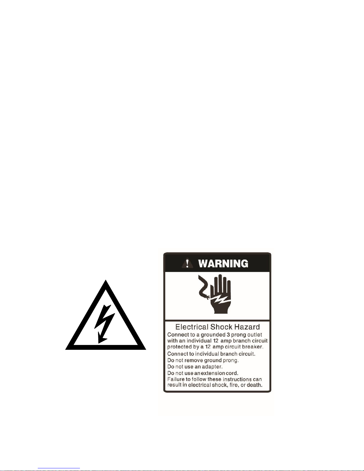
To prevent electric shock, always unplug an appliance from the power supply before attempting
any service.
Disconnect the power cord by grasping the plug, not the cord.
Do not bypass, cut, or remove the grounding plug.
Prevent water from spilling onto electric elements or the machine parts.
Always refer to the rating label on the appliance for rated current and voltage.
Always check line voltage and amperage.
Always use exact replacement parts.
Any attempt to repair a major appliance may result in personal injury and property damage.
Page 3
2
Electrical Safety
Do not exceed the power outlet ratings.
It is recommended that the unit be connected to its own circuit.
A standard electrical supply (120V, 60Hz), that is properly grounded in accordance with the National
Electrical Code and all state and local codes and ordinances is required.
Do not use outlets that can be turned off by a switch or pull chain.
Always turn the unit off and unplug it from the outlet when cleaning.
Unplug the unit if it is not going to be used for an extended period of time.
Do not operate the unit with a power plug missing the ground plug, a damaged cord, or a loose socket.
Be sure the appliance is properly grounded.
Do not bypass, cut, or remove the grounding plug.
If the power cord is damaged, it must be replaced by the manufacturer or a qualified technician.
Do not use extension cords or power strips with this unit. You may need to contact an electrician if it is
necessary to use a longer cord or if you do not have a properly grounded outlet. Do not modify the
power cord’s length or share the outlet with other appliances.
Do not start or stop the unit by switching the electrical circuit’s power on and off.
Immediately unplug the unit if it makes strange sounds, emits an odor or smoke and contact customer
service.
Do not remove any part of the casing unless instructed by an authorized technician.
Before the appliance is removed from service or discarded, remove the door and cut off the power
cord.
Page 4

3
General Safety
Always unplug an appliance from the power supply before attempting any service. Disconnect the
power cord by grasping the plug, not the cord.
Do not allow children or pets to play on or in the appliance.
This machine is not intended for use by persons (including children) with reduced physical, sensory or
mental capabilities, or lack of experience and knowledge, unless they have been given supervision or
instruction concerning use of the machine by a person responsible for their safety.
Do not install or store this appliance where it will be exposed to the weather.
Disconnect from the power socket before cleaning or maintenance.
If the plug (power cord) is damaged, it must be replaced by the manufacturer or an authorized service
representative.
This machine shall be repaired only by an authorized service representative. Only genuine
replacement parts should be used.
If connected to a circuit protected by fuses, use time-delay fuses with this appliance.
Do not lean items against the glass door.
Please do not close the door with excessive force. If it is found difficult to close the door, please check
for obstruction.
When you plan to dispose of this unit in the future, please comply with the local waste disposal
regulations. Remove the door so that children and pets will not be trapped in the unit.
Page 5
4
IB450SSP Introduction
The IB450SSP is comprised of 3 systems: The Cooling System, Water System and
Electrical System.
Note: Please refer to the IB450SSP User Manual for installation and other use and care
guidelines.
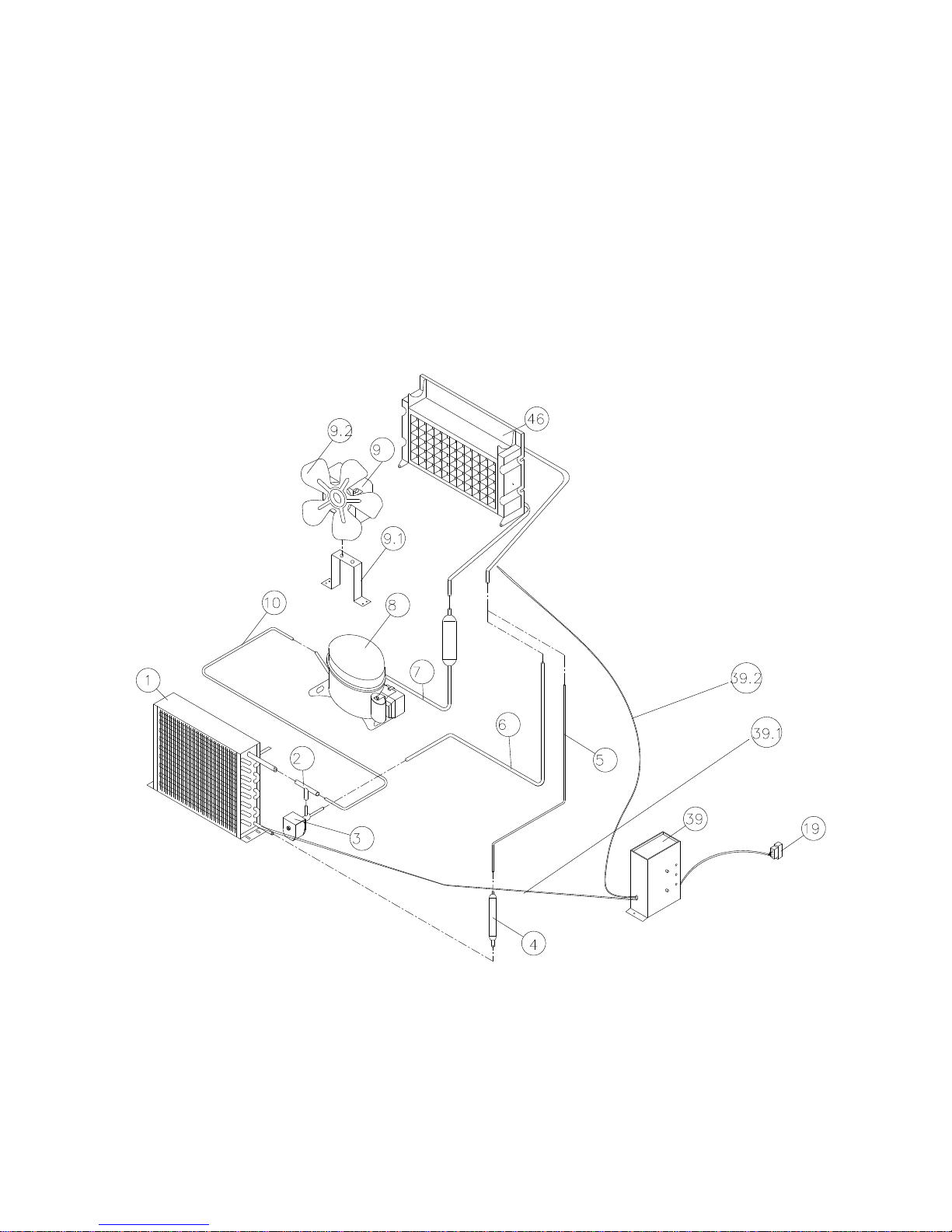
Cooling System Overview
Page 6
5
Cooling System Parts List
ITEM NO.
DESCRIPTION
1
Condenser
2
Multi-connection copper pipe
3
Hot gas solenoid valve
4
Filter Dryer
5
Capillary tube
6
Hot gas tube
7
Suction tube
8
Compressor
9
Fan motor
9.1
Fan motor bracket
9.2
Fan blade
10
Discharge tube
19
Wiring harness
39
Control box
39.1
Temperature sensor for the condenser
39.2
Temperature sensor of the evaporator
46
Evaporator (Ice Mold)
During the ice making stage the hot gas solenoid valve is closed. The hot refrigerant gas is pumped out
of the compressor to the condenser. The hot gas is cooled by fan forced air after passing through the
condenser. The filter dryer helps reduce dirt and moisture in the refrigerant. The evaporator is cooled by
the refrigerant. Ice is formed on the evaporator as water is sprayed onto the evaporator. Low pressure
refrigerant gas goes back to the compressor from the evaporator.
During the ice harvest stage, the solenoid valve is open. The hot refrigerant gas is pumped out of
compressor to evaporator through the hot gas valve. As the hot gas passes through the evaporator it
warms and the ice touching it is slightly thawed and releases from the evaporator. The harvested ice then
proceeds down the slide way into the ice storage bin.
Page 7
6
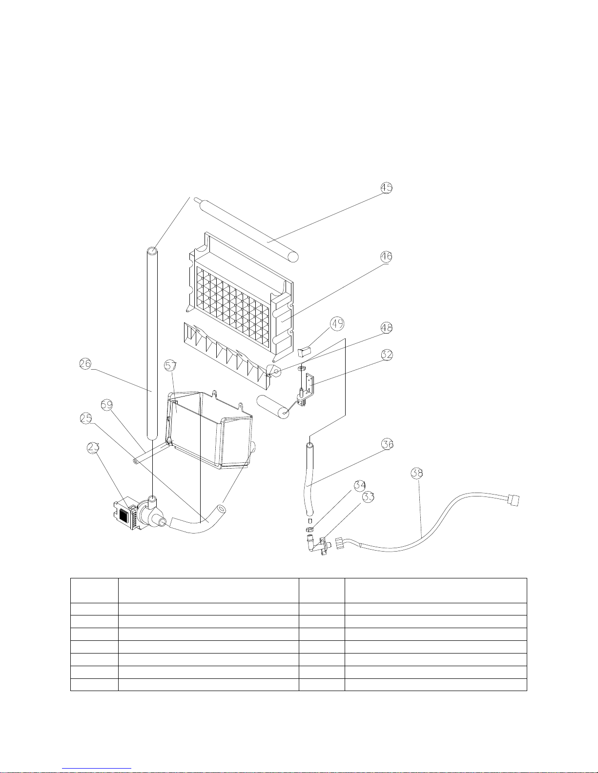
Water System
When the water supply hose (No. 38) is connected with the main water supply, water will fill the water bin
(No. 57) through the float valve (No. 32) until water fills the bin enough to make the float valve close.
During ice-making stage, water is pumped from the water bin to the water distribution tube (No. 45.) The
water then flows over the surface of evaporator. Most of water goes back to the water bin. Some water is
frozen onto the evaporator little by little. When water in the bin falls below a certain level the float valve
will open and fill the bin again.
ITEM
NO.
DESCRIPTION
ITEM
NO.
DESCRIPTION
23
Water Pump
38
Water Supply Hose
25
Water Pump Inlet Tube
45
Water Distribution Tube
26
Water Pump Outlet Tube
46
Evaporator
32
Float Valve
48
Ice Slide Way
33
Water Inlet Valve
49
Ice Full Sensor
34
Water Inlet Nut
57
Water Bin
36
Water Inlet Tube
59
Water Bin Drain Tube
Page 8

7
Electrical System
Ice-Making Stage - The compressor, condenser fan and pump are powered on, the water inlet valve and
hot gas solenoid valve close and the Green LED on the control panel is lit. When the unit is in this stage it
is controlled by a temperature probe on the evaporator. When the Green LED starts flashing the stage is
controlled by a fixed timer. The fan motor is also controlled by a temperature probe (on the condenser.)
When the ambient temperature is too low the fan stops working to maintain the correct temperature.
Ice-Harvest Stage – In this stage the water pump turns off. The hot gas solenoid, compressor and fan
are powered on. The Yellow LED is lit to indicate the ice harvest stage. This stage is controlled by a fixed
timer.
Bin-Full Stage - When the ice bin is full of ice and/or the ice slide way is held open the unit will enter this
stage. In this stage all electrical components are powered off and the Red LED on the control panel is lit.
Cleaning Stage – Press the button marked Clean on the control panel to start the cleaning stage. The
pump and water inlet valve are powered on, and the compressor, condenser fan and solenoid valve are
powered off. The Green and Yellow LEDs will flash together. To stop the cleaning stage simply press the
Clean button again.
Page 9

8
IB450SSP Controls / Control Box
LEDs and Buttons
Red LED: Ice-Full indicator light. This LED is lit when the ice storage bin is full of ice or there is something
between the two arms of the ice-full sensor in the ice storage bin. The electrical components turn off and
the unit will go to sleep. When ice cubes are taken out of the ice storage bin, clearing the sensor, the red
LED will flash for 3 minutes. Then the unit will then restart and return to the ice-making stage.
Green LED: Ice-Making indicator light. This LED is lit when the unit is in the Ice-Making stage controlled
by a temperature probe on the evaporator. When the green LED is flashing, the unit is in the Ice-Making
stage controlled by a fixed timer.
Yellow LED: Ice-Harvest indicator light. This LED is lit when the unit is in the Ice-Harvest stage controlled
by a temperature probe on the evaporator. When the yellow LED is flashing, the unit is working in the Ice
Harvest mode controlled by a fixed timer.
Clean Button: Pressing this button puts the unit into cleaning mode. The green and yellow LEDs flash
together and the pump turns on to flush the unit with water. Press the button again to exit cleaning mode.
Mode Button: This button is mainly for service. When this button is pressed, the unit changes from IceMaking stage to Ice-Harvest stage, or from Ice-Harvest stage to Ice-Making stage. The status of the
green and yellow LEDs indicate the stage.
Adjust Button: Pressing this button for over 3 seconds will put the unit into Ice Cube Size Adjustment
Mode. The status of the green LED indicates the various stages of this mode. After 10 seconds without
any operation the unit will return to normal operations.
Ice Cube Size Adjustment Guide:
1) Press and hold the Adjust button for at least 3 seconds. The unit will enter the Ice Cube Size
Adjustment mode. The Ice-Making/Green LED will blink continuously during the ice size adjustment.
Release the Adjust button when the LED starts to blink and continue to step 2 to adjust the ice cube size.
2) While in the Ice Cube Size Adjustment mode, press the Clean button or the Mode button to decease or
increase ice cube size.
Page 10

9
Smaller ice cube setting:
Pressing the Clean button decreases the size of the ice cubes. The Ice-Full/Red LED will flash as you
decrease the ice size and will finally blink once it has reached the smallest setting.
Larger ice cube setting:
By pressing the Mode button, you can increase the size of the ice cubes. The Ice-Harvest/Yellow LED will
flash as you increase the ice cube size and will finally blink once it has reached the largest setting.
NOTE: During the ice size adjustment, the Ice-Full, Ice-Making and Ice-Harvest LEDS blinking all at once
indicate that the unit is in the regular (middle) setting of the ice cube size. When the machine is in the
cleaning stage or ice full stage, the ice size is not available for adjusting.
Page 11

10
Exploded View Diagram
Page 12

11
Parts List
No.
Description
No.
Description
1
Door handle
35
Drain connector
2
Door
37
Bottom hinge
3
Ice storage bin
38
Left bracket
4
Ice scoop
39
Power cord
6
Water distribution tube
40
Wire harness
7
Evaporator (ice mold)
41
Capillary tube
8
Evaporator sensor
42
Filter dryer
9
Ice slide way
43
Compressor
10
Ice full switch
44
Discharge pipe
12
Water bin
45
Right bracket
13
Kick plate
47
Fan motor
14
ICE/OFF/WASH switch
48
Fan blade
15
Cabinet
49
Condenser sensor
16
Top hinge
50
Hot gas solenoid
17
Hinge pin
51
Electromagnetic valve body
18
Transformer
52
Hot gas pipe
19
Control box
53
Filter dryer
20
Control box bracket
54
Fan motor bracket
21
Back panel
55
Condenser
22
Pump outlet tube
56
Base plate
23
Pump inlet tube
57
Leveling leg
24
Water pump
58
Leveling leg
25
Pump mat
63
Drain pump wire harness
26
Pump bracket
64
Drain pump
27
Water supply hose
65
Drain pipe outlet
28
Water inlet tube
66
Drain pipe inlet
30
Float valve
68
Water bin
32
Water inlet valve
69
Water level switch
34
Drain pipe
70
Drain pipe connector
Page 13

12
TROUBLESHOOTING
Basic Precautions
1. Make sure the unit is connected to a 115 Volt, 60Hz. AC only 15 amp electrical supply and is
properly grounded to protect against electrical shock.
2. Make sure the power cord is not damaged.
Basic Checks
Listen
Listen to the customer's description of the problem with the icemaker. Try to understand what the
current defect is and how the unit operated before calling for service.
Listen to how the unit sounds when it runs. Often times problems can be diagnosed by sound(s)
or lack of sound.
See
Check the copper lines of cooling system, especially at the welding points. If oil is seen around
any part of the cooling system it is likely due to a refrigerant leak.
Check if the ice-making and ice-harvest cycles are normal. Too long or too short a cycle may
result in a system malfunction.
Check the water system for leaks, especially at the connections. Make sure the pump drain cap
on the rear of the unit is tight and doesn’t leak.
Check the water filter (if installed.) A dirty filter needs to be replaced.
Check if the icemaker is installed according to the user’s manual.
Check if the icemaker needs to be cleaned. Lack of regular cleaning will result in problems and
may cause health issues.
Touch
Touch the discharge line from the compressor and make sure it is hot. Touch the suction line and
make sure it is cool.
Touch the top of the evaporator. It will be cold during Ice-Making and warm up during Ice-
Harvest.
Page 14

13
Advanced Troubleshooting Guide
The troubleshooting guide in the user manual should be referred to before this guide. Turn to this guide
when the user manual does not solve the issue.
The Unit Does Not Make Ice
Problem
Check point
Possible Cause
Correction
Unit will not turn
on
Plug
The icemaker is unplugged.
Plug in the icemaker.
Wall Socket
Socket is damaged.
Repair or replace.
Power Switch
The icemaker power
switch is OFF.
Turn the power switch to
ON.
Fuse
The fuse is blown.
Replace fuse.
Wiring Connections
A wiring connection is
incorrect, damaged or loose.
Check, repair and/or re-
connect.
Voltage
The voltage to the power PCB
is low.
Repair or replace wall
socket or power cord.
Ice Full Sensor
The ice full sensor is defective
(The icemaker will stop after it
completes 18 cycles.)
Replace sensor.
Ice Full Sensor
The ice full sensor is
covered by something.
Clean and clear the
sensor.
Electric Component
Electric component failure (i.e.
fan, PCB, etc.)
Pressing the mode
button to change the
modes is helpful in
diagnosing.
Control Board
The control PCB is damaged
or defective.
Replace.
Water Supply
The water supply tap is turned
off or not all the way up.
Turn on the water supply
tap on fully.
Water
System
Water Supply Pipe
The water supply pipe is not
properly connected or
maybe kinked.
Reconnect the water
supply pipe.
Water Line
Water line leaks.
Repair connection or
replace line.
Water Line
The water line is blocked.
Clean line, see user
manual "ice making
system cleaning"
Water Inlet Valve
Water supply pressure is low.
Turn water supply on
fully to maximize
pressure.
Water Inlet Valve
Water inlet valve is loose.
Check and re-connect.
Water Pump
Water pump damaged or
defective.
Replace water pump.
Water Pump
If room temperature is out the
stated range the water pump
stops automatically.
Adjust temperature
within the stated range.
Water Pump
Wires on the water pump
loose, damaged or
disconnected.
Check, repair and/or reconnect.
Page 15

14
Water Pump
The housing of water pump
leaks.
Replace water pump.
Compressor will
not run
Wiring connections
A wiring connection is
incorrect, damaged or loose.
Check, repair and/or reconnect.
Start Relay and
Overload Protector
One or both defective.
Replace both relay and
overload protector.
Compressor Start and
Run Coils
The compressor is short
circuited.
Replace the
compressor.
Condenser
The condenser may be dirty.
Clean the condenser.
Fan
The fan may be dirty or
damaged.
Clean or replace the fan.
Power Board
The board is damaged is or
defective.
Replace the board.
Compressor
runs but no ice
is produced
Refrigerant
Refrigerant leak.
Add low side access
valve, locate and repair
leak, replace dryer, add
nitrogen, pull vacuum
and weigh in the
refrigerant charge
indicated on the data
plate.
Capillary tube
Capillary tube is blocked.
Add low side access
valve, locate and repair
leak, replace dryer, add
nitrogen, pull vacuum
and weigh in the
refrigerant charge
indicated on the data
plate.
Vent / Fans /Condenser
The airflow is obstructed
around the ice machine.
Clean the vent, fans,
and condenser.
Hot gas valve
Hot gas valve damaged or
defective.
Replace valve.
Control Board
The control PCB is damaged
or defective.
Replace.
Page 16

15
Low Ice Production
Problem
Check point
Possible Cause
Correction
Cooling
System
Refrigerant
Partial refrigerant leak.
Repair leak and
recharge.
Condenser
The condenser may be dirty.
Clean the condenser.
Ambient Temperature
The ambient temperature is
above 90F or below 65F.
Adjust the ambient
temperature or move
unit to better location.
Fan
The fan is dirty or damaged.
Clean or replace fan.
Hot Gas Valve
Defective valve.
Replace the hot gas
valve
Water System
Bin Drain
The bin drain may be partially
restricted.
Clean out the drain and
check lines.
Water line
Water line restricted.
Clean line and install a
water filter.
Rubber Water Tubes
Tubes distorted, kinked,
leaking or blocked.
Clean, repair or replace
tubes.
Unit Dirty
Unit has not received regular
cleaning.
Clean unit as outlined in
the User Manual.
Page 17

16
Ice Cubes Are Deformed or Wrong Size
Problem
Check point
Possible Cause
Correction
Ice Cubes Too
Small
Condenser
The condenser or fans are
dirty or the air vents are
covered.
Clean the condenser and
fans. Leave space around
the machine.
Ambient Temperature
The ambient temperature is
too high.
Adjust the ambient
temperature.
Electronic controller
The ice size is set too small.
See “Ice Cube Size
Adjustment Guidelines” in
this manual.
Refrigerant
Refrigerant leak.
Repair and recharge.
Ice Cubes Too
Large
Electronic controller
The ice size is set too Large.
See “Ice Cube Size
Adjustment Guidelines” in
this manual.
Sensor
The evaporator sensor is
defective.
Replace the sensor.
Ambient Temperature
The ambient temperature is
too low.
Adjust the ambient
temperature.
Ice Cubes Only
Partially
Formed or
Have Ragged
Sides
Water Quality
The water quality is poor.
Install a water-softener or
water filter in front of the
water inlet valve.
Spray Nozzle
Spraying is blocked by the ice
slide way.
Adjust the location of the
ice slide way.
Spray Bar
Spray bar obstructed.
Clean the spray bar see
the user's manual.
Water bin
Not enough water in the water
bin.
Check water supply filter
may be restricted.
Water Pressure
Water supply pressure is low.
Turn water supply on fully
to maximize pressure.
The Room
Temperature
The room temperature is out
the stated range.
Adjust the ambient
temperature.
Page 18

17
Other problems
Problem
Check point
Possible Cause
Correction
The Unit Body
is Electrified
Ground
The ground plug is broken.
Replace power cord.
Lines
Shorted wiring.
Adjust, reconnect
/replace wires.
Electric component
Shorted electric component.
Replace component.
Scales Occur
Frequently
Inside Unit
Water Quality
The water quality is poor.
Install a water-softener or
water filter in front of the
water inlet valve.
Noise During
Operation
Water Inlet Valve
Defective water inlet valve.
Replace the water inlet
valve.
Compressor
Excessive noise/vibration.
Tighten compressor bolts
or replace the
compressor.
Water Pump
Defective water pump.
Replace the water pump.
Cooling System
Refrigeration pipes vibrating.
Adjust pipes.
Leveling Legs
The feet are not leveled.
Level and lock the feet.
Fan Motor
The fan motor is loose or
defective.
Repair or replace the fan
motor.
Water Leaking
Out of Unit
Water Supply
Connection
Water connection leaking.
Tighten fitting. See
“Connecting the water
line.”
Water Pump Drain Cap
Leaking around cap.
Tighten fitting.
Drain Pipe Connection
Drain pipe connection leaking.
Tighten fitting. See
“connecting the drain.”
Ice Harvesting
is Difficult
Hot gas valve
The hot gas valve damage.
Replace the hot gas
valve.
Evaporator
The evaporator is dirty or finish
is damaged.
Clean the ice mold, or
replace the evaporator.
Refrigerant
Refrigerant leaks
Recharge
Ambient Room and
Water Temperature
Temperature is too low.
Adjust the temperature.
Ice Cube Size
Size is too large.
See “Ice Cube Size
Adjustment Guidelines” in
this manual.
Ice Slide Way
Ice slide way is installed
incorrectly.
Reinstall ice slide so
harvested ice does not
get stuck or blocked.
Page 19

18
Replacing Water System Components
Replacing the water pump
Disconnect electrical power.
Remove the rear cover
Unplug the lines connected to the water pump, the water outlet tube and the water inlet tube.
Loosen the screws and replace with a new one.
Reverse the above steps to reassemble.
Replacing the water inlet valve
Note: If the water inlet valve does not work at all, or does not shut off tightly, it should be
replaced.
Unplug or disconnect electrical power.
Loosen the water supply pipe, remove the water panel, loosen 2 screws holding the water inlet
valve, unplug the lines and loosen the water valve outlet tube.
Replace a new one, reverse the above step to reassemble.
Unscrew the water drain cap and drain off the waste water into a
bucket or other suitable drain port. Next, re-secure the drain cap
and tighten.
Page 20

19
Replacing Cooling System Components
NOTE: Please see the cooling system diagram. Please check for refrigerant leaks after any service
is performed to the cooling system.
Replacing the compressor start relay and overload protector.
To replace the relay and overload protector, remove the rear panel, locate the compressor, take
the clip off the cover to relay and overload protector, open the cover, replace the relay and
overload protected.
Reverse the above steps to reassemble.
To replace the compressor, remove the rear panel, and left side, and locate the compressor.
Add low side access valve, locate and repair leak, replace dryer, add nitrogen, pull vacuum and
weigh in the refrigerant charge indicated on the data plate.
Reverse the above steps to reassemble.
Replacing the fan motor.
Remove the top cover, rear and left sides.
Locate the fan motor, unplug the lines connected to the fan motor, loosen the screws of the
bracket holding fan motor to the base. Replace with new fan.
Reverse the above steps to reassemble.
Replacing the hot gas valve and filter dryer.
Remove the rear, top cover and the left side.
Locate the dryer and hot gas valve, add low side access valve, recover refrigerant, replace dryer
and valve, add nitrogen, pull vacuum and weigh in the refrigerant charge indicated on the data
plate.
Reverse the above steps to reassemble.
Page 21

EdgeStar, 8606 Wall St, Suite 1800, Austin, TX 78754
support.edgestar.com • service@edgestar.com • edgestar.com
*Warranty service should be performed by an authorized service representative only.
DATE
REVISION NOTES
02/06/2018
INITIAL DOCUMENT
 Loading...