

Page 1
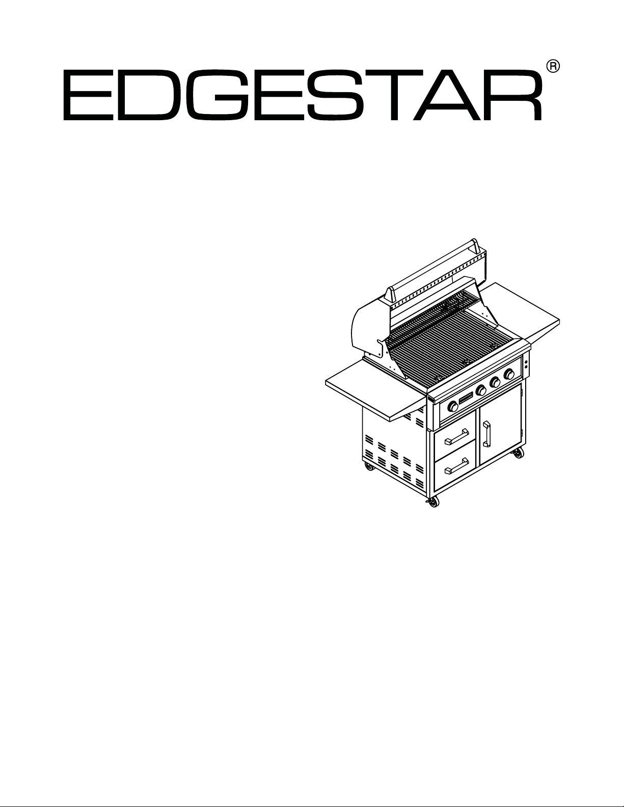
BBQ Grill
GRL270IBNG / GRL270IBLP
GRL300IBNG / GRL300IBLP
GRL360IBBNG / GRL360IBBLP
GRL420IBBNG / GRL420IBBLP
Service Manual
V2.0 11122019www.edgestar.com
Page 2
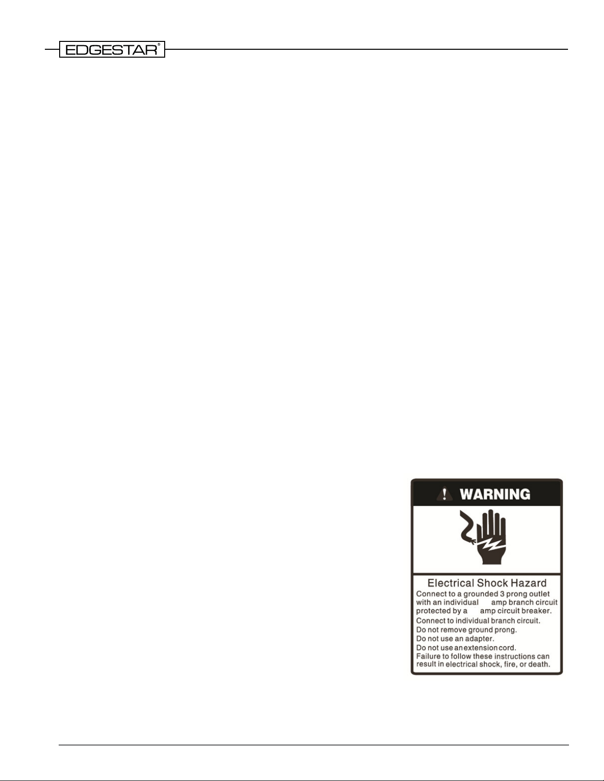
Table of Contents
Safety Precautions ..................................................................................................................... 2
Important Safety Information ...................................................................................................... 4
Parts Identication ...................................................................................................................... 6
Grill Dimensions ......................................................................................................................... 10
Part Maintenance and Replacement .......................................................................................... 14
Replacing the Temperature Gauge ..................................................................................... 14
Replacing the Grill Handle .................................................................................................. 15
Replacing the Hood ............................................................................................................ 16
Replacing the Internal Light ................................................................................................ 17
Removing Control Panel ..................................................................................................... 18
Replacing the LED Knob Lights and Wires ........................................................................ 19
Replacing the Orice .......................................................................................................... 21
Replacing the Gas Burner Valves ....................................................................................... 22
Replacing the Burners ........................................................................................................ 23
Replacing the Warming Rack Support Bracket .................................................................. 23
Replacing the Rear Infrared Burner (Rottisserie) ............................................................... 24
Replacing the Stainless Steel Flexline .............................................................................. 25
Replacing the Rear Infrared Burner Igniter ......................................................................... 26
Replacing the Thermocouple .............................................................................................. 27
Replacing the Rear Infrared Burner Valve .......................................................................... 29
Safety Precautions
WARNING: This manual and the information contained herein is intended for use by certied
technicians. The manufacturer or seller is not responsible for the interpretation or misuse of the
information provided, nor does it assume any liability in connection with its use.
The safeguards and warnings indicated in this manual do not cover all possible conditions which may
occur. Common sense, caution, and care must be exercised.
• To prevent electric shock, always unplug an appliance from the
power supply before attempting any service.
• Disconnect the power cord by grasping the plug, not the cord.
• Do not bypass, cut, or remove the grounding plug.
• Prevent water from spilling onto electric elements or the
machine parts.
• Always refer to the rating label on the appliance for rated current
and voltage.
• Always check line voltage and amperage.
• Always use exact replacement parts.
• Any attempt to repair a major appliance may result in personal
injury and property damage.
15
15
2
Page 3
Danger: If you smell gas:
• Shut o gas to the appliance.
• Extinguish any open ame.
!
• Open lid.
• If odor continues, keep away from the appliance and immediately call your gas
supplier or your re department.
Warning: Grills must have 24” clearance on all sides from combustible materials. If
!
installed in or near combustible fabrication materials, an insulated jacket MUST be used.
Warning:
• Do not store or use gasoline or other ammable liquids or vapors in the vicinity of this
!
or any other appliance.
• An LP cylinder not connected for use shall not be stored in the vicinity of this or any
other appliance.
Beware of Spiders!
Spiders and small insects occasionally spin webs or make nests in the burners during
warehousing, transit, and/or after a zlong period of not using the grill. These webs can
lead to a gas ow obstruction, which could result in a re in and around the burner
tubes. This type of re is known as “ashback” and can cause serious damage to your
grill and create an unsafe operating condition for the grill user. Although an obstructed
burner tube is not the only cause of “ashback,” it is the most common cause. Frequent
inspection of the burners is necessary.
Natural Gas Safety
• Natural gas grill (models GRL****NG) is designed to operate on natural gas only at a pressure
regulated at 4 inches water column (WC) when equipped with the correct natural gas orices on
the valves and a natural gas regulator on the supply line.
• Burners must be inspected and cleaned before each use.
• Never connect the grill to an unregulated natural gas supply.
• Check with your gas company or with local building codes for instructions on how to set up a
proper gas supply line.
• Use a licensed and knowledgeable installer to connect the gas lines to your grill.
• Pipe sealing compound or pipe thread tape that is suitable for use with natural gas must be used
on all male pipe thread. Apply compound or tape to at least the rst three threads when making the
connection.
• The grill must be isolated from the gas supply piping system by closing its individual manual
shuto valve during any pressure testing of the gas supply line at test pressures less than or equal
to ½ PSI (3.5 kPa).
• Turn o your gas grill when the gas supply is being tested at low pressures. This appliance must
be isolated from the gas supply piping system by closing its individual valve.
• Some states and municipalities have special licensing requirements for the handling of gas.
Reference the regulations of local authorities prior to installation.
3
Page 4
Important Safety Information
Gas and Electrical Safety
• This gas grill must be installed in accordance with all local codes. In addition, the gas grill(s) must
be installed in accord with the following codes, as applicable:
• National Fuel Gas Code, ANSI Z223.1 / NFPA 54
• Natural Gas and Propane Installation Code, CSA B149.1
• Propane Storage and Handling Code, CSA B149.2
• Where applicable, a standard electrical supply (115V, 60Hz) must be used for lights, rotisserie
motor(s), and all other apparatus that need to be plugged in. Electrical supplies must be properly
grounded in accordance with the National Electrical Code, ANSI / NFPA 70. Compliance with local
codes and ordinances is required.
• Never use dented, rusty, or damaged propane tanks.
• Always have an ABC re extinguisher nearby. Never attempt to use water to extinguish a grease
re.
• Check the tubes that lead into the burner for any blockage from insects, spiders, or food grease.
• Liquid petroleum (LP) or propane is highly ammable. Treat with care.
• Do not repair gas tanks yourself; seek repair from an authorized repair person.
• Do not repair damaged gas connectors, tank valves, or supply hoses.
• Store gas tanks in an upright, contained, and secure area. Do not leave lled tanks in a hot car or
car or car trunk.
• Check for gas leaks. If you detect a leak, immediately turn o the gas and do not attempt to ignite
the grill until the leak is xed.
• Never light cigarettes or matches, or expose open ames in the presence of a gas leak.
• Do not exceed the power outlet ratings.
• Keep any electrical supply cord and the fuel supply hose away from any heated surfaces.
• To protect against electric shock, do not immerse power cords or plugs in water or other liquids.
• Use outlets that cannot be turned o by a switch or pull chain.
• Do not operate any apparatus or accessories with power plugs missing the ground plug, a
damaged cord, or a loose socket. Do not bypass, cut, or remove the grounding plug.
• Unplug the unit if it is not going to be used for an extended period of time.
• Never plug or unplug the unit with wet hands.
• Do not use extension cords or power strips with this unit. You may need to contact your electrician
if it is necessary to use a longer cord or if you do not have a grounded outlet. Do not modify the
power cord’s length or share the outlet with other appliances.
• Do not start or stop the unit by switching the circuit’s power on and o.
• If the power cord is damaged, it must be replaced by the manufacturer or a qualied technician.
• Never repair the unit while it is plugged in.
• Immediately unplug the unit if it makes strange sounds, emits smells or smoke comes out of it, and
contact customer service.
• You should never attempt to repair the unit yourself. Contact customer service for service options if
the unit needs service.
• Never use charcoal or any other non-approved or solid fuel sources. This manual covers grills
fueled by gas (LP and NG) only.
4
Page 5
General Safety
!
• To prevent back and other types of injuries, use at least two people to move and install the grill(s)
and grilling equipment.
• This appliance is not intended for use by persons, including children, with reduced physical,
sensory or mental capabilities, unless they have been given supervision or instruction concerning
the use of the appliance by the person(s) responsible for their safety.
• Install the gas grill(s) in a well-ventilated area.
• Do not place hot or warm items into the cooler before they cool down to room temperature.
• This grill should not be installed indoors or in a garage, RV, under a carport, etc. Keep away from
surfaces that can catch re.
• This grill should be installed in a well-ventilated area. It is recommended that it is protected from
direct rain, sleet, snow, and / or moisture.
• This grill is not intended to be used by children.
• Children should be supervised to ensure that they do not play with this product.
• Never allow children to crawl inside the grill.
• Do not use this appliance near combustibles such as gasoline, benzene, thinner, etc.
• Take care when working with the gas grill as there will be extremely hot surfaces.
• Only use in an upright position on a at, level surface and provide proper ventilation.
• Do not pinch or kink the power supply line between the unit and cabinet.
• Do not leave any cleaning solutions in the unit.
• Do not use solvent-based cleaning agents or abrasive solutions to clean the unit as they may
damage the interior and exterior.
• Do not place any other appliances on top of the unit.
• Do not turn the unit upside down, on its side or at an angle o level.
• The Consumer Product Safety Commission recommends keeping the grill at least 10 feet away
from your house or any building.
• Maintain all clearance requirements detailed in this user’s manual.
• Follow all food safety and handling requirements required by local codes. Do not let food sit
[unrefrigerated] for more than one hour before or after cooking.
• Never leave the grill unattended while cooking.
• Never cook without the drip tray in place.
Propane Gas Safety
• Your propane gas grill (models GRL****LP) is designed to operate on propane gas only at a
pressure regulated at 11 inches water column (WC) when equipped with the correct propane
orices on the valves and a propane regulator on the supply line.
• EdgeStar LP grills are designed to be used with a standard 20 lb. (9.1kg) Department of
Transportation (DOT) approved LP cylinder. No tanks larger than 20 lbs. are to be used. The tank
must be marked in accordance with the latest DOT specication for LP gas tanks: Specications
for LP gas Cylinders (DOT CFR49).
• Burners must be inspected and cleaned before each use.
• Do not store a spare LP gas cylinder under or near this appliance.
• Never ll the cylinder beyond 80 percent full.
• Never store an LP gas cylinder inside a building or in the vicinity of any gas-burning appliance.
• Always keep LP gas cylinders fastened in an upright position.
• Never connect an unregulated LP gas cylinder to the grill.
• Do not subject LP gas cylinders to excessive heat.
• If the information above is not followed exactly, a re causing death or serious injury may occur.
5
Page 6
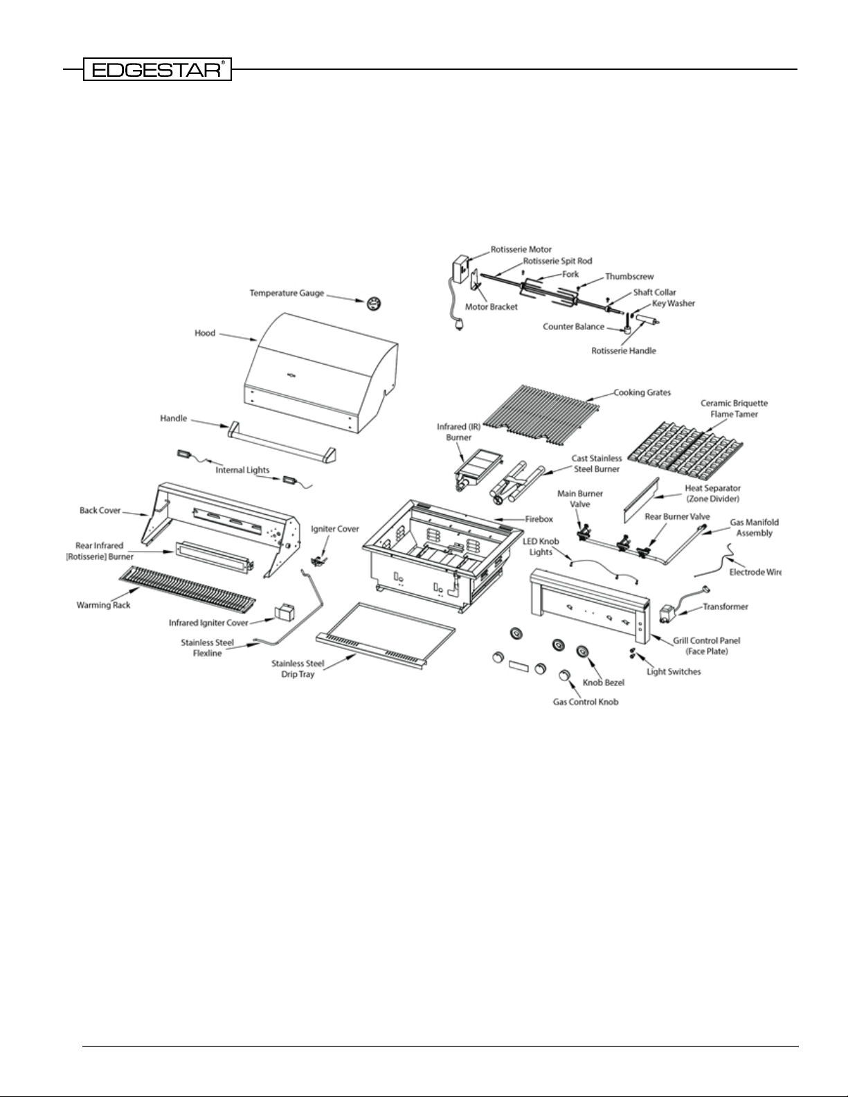
Parts Identication
GRL270IBNG / GRL270IBLP
GRL300IBNG / GRL300IBLP
(Two Burner Gas Grills)
6
Page 7
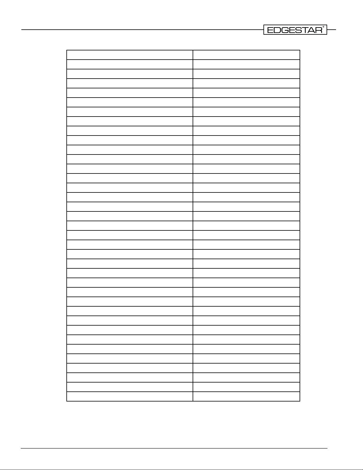
Part Name Quantity
Temperature Gauge 1
Hood 1
Handle 1
Internal Lights 2
Back Cover 1
Rear Infrared Burner 1
Warming Rack 1
Infrared Igniter Cover 1
Igniter Cover 1
Stainless Steel Flexline 1
Stainless Steel Drip Tray 1
Firebox 1
Infrared (IR) Burner 1
Cast Burner 1
Gas Control Knob 3
Knob Bezel 3
Light Switch 2
Control Panel (Face Plate) 1
Transformer 1
Electrode Wire 1
LED Lights 3
Main Burner Valve 1
Rear Infrared Burner Valve 1
Gas Manifold Assembly 1
Heat Separator (Zone Divider) 1
Flame Tamer 1
Cooking Grates 2
Rotisserie Motor 1
Motor Bracket 1
Rotisserie Spit Rod 1
Fork 2
Thumbscrew 4
Shaft Collar 1
Key Washer 1
Rotisserie Handle 1
Counter Balance 1
7
Page 8
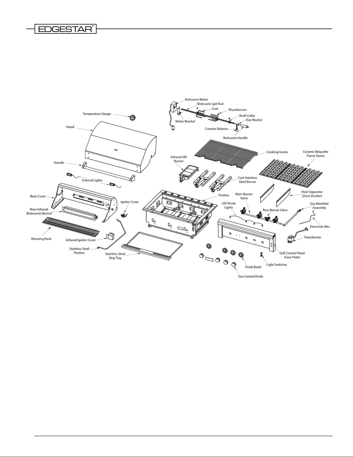
GRL360IBBNG / GRL360IBBLP
GRL420IBBNG / GRL420IBBLP
(Three Burner Gas Grills)
8
Page 9
Part Name Quantity Included
Temperature Gauge 1
Hood 1
Handle 1
Internal Lights 2
Back Cover 1
Rear Infrared Burner 1
Warming Rack 1
Infrared Igniter Cover 1
Igniter Cover 1
Stainless Steel Flexline 1
Stainless Steel Drip Tray 1
Firebox 1
Infrared (IR) Burner 1
Cast Burner 2
Gas Control Knob 4
Knob Bezel 4
Light Switch 2
Control Panel (Face Plate) 1
Transformer 1
Electrode Wire 1
LED Lights 4
Main Burner Valve 2
Rear Infrared Burner Valve 1
Gas Manifold Assembly 1
Heat Separator (Zone Divider) 2
Flame Tamer 2
Cooking Grates 3
Rotisserie Motor 1
Motor Bracket 1
Rotisserie Spit Rod 1
Fork 2
Thumbscrew 4
Shaft Collar 1
Key Washer 1
Rotisserie Handle 1
Counter Balance 1
9
Page 10
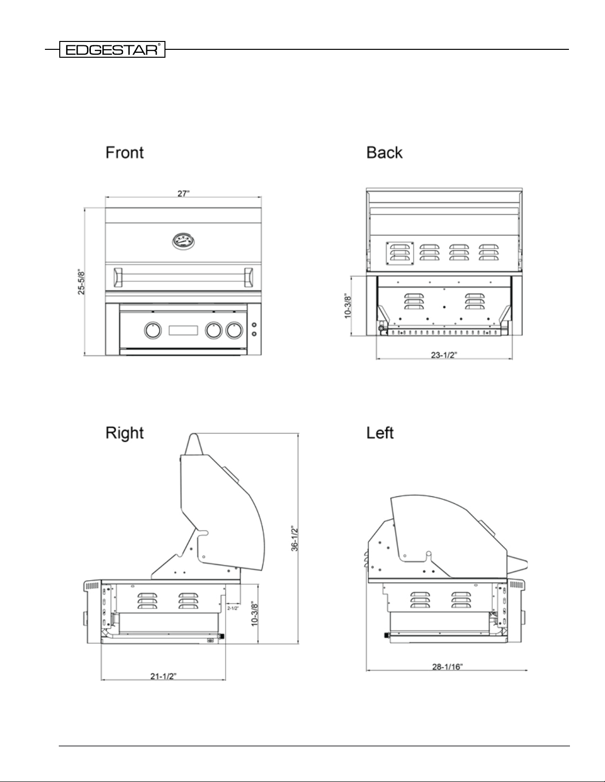
Grill Dimensions
GRL270IBNG / GRL270IBLP
10
Page 11

GRL300IBNG / GRL300IBLP
11
Page 12

GRL360IBBNG / GRL360IBBLP
12
Page 13

GRL420IBBNG / GRL420IBBLP
13
Page 14

Part Maintenance and Replacement
Replacing the Temperature Gauge
Tools Needed:
• Phillips Screwdriver • M8 Hex Socket Wrench
1) Remove the two screws from the temperature gauge seal with a Phillips screwdriver and remove
the seal.
2) Remove the two M8 ball nuts from the temperature gauge with an M8 hex socket wrench. Hold
the temperature gauge to prevent it from slipping o the surface, then remove the temperature
gauge and the cover ring.
3) Install the new temperature gauge and cover ring and replace the M8 ball nut on the top cover.
4) Replace the seal and tighten the two screws securely.
14
Page 15

Replacing the Grill Handle
Tools Needed:
• Phillips Screwdriver
1) With the lid open, stabilize the handle. Then remove the four large screws holding the handle in
place from inside the lid.
NOTE: The screws will drop straight down when they are removed. Be careful not to drop them into
other grill components.
2) Attach the new handle by placing it rmly in the mounting hole. Do not tighten the screws on a
particular side until the screws on the other side have been inserted.
15
Page 16

Replacing the Hood
Note: This service requires two persons.
Tools Needed:
• Flat Screwdriver • M10 Hex Socket Wrench
1) Open the hood and stabilize the entire unit.
2) Use an M10 wrench to hold the locking nut and use a at-head screwdriver to remove the screw
holding the hood in place. Repeat for both sides.
3) Pull the hood from the rear and remove it from the grill.
4) Perform the above steps in reverse to install the new hood.
16
Page 17

Replacing the Internal Light
Tools Needed:
• Phillips Screwdriver • Long String
1) Remove the connection terminal that connects the internal light to the main electric wire. Attach a
long string to the connector.
2) Open the light cover by removing the phillips head screw.
2) Pull the light straight down while feeding the light cable (with string attached) through the unit.
Untie the string from the old light cable, tie string to new light cable, and pull string and cable back
into the unit from the other end.
3) Insert the new internal lamp in the same position, noting that the long foot is on the left.
4) Reattach the light cover and tighten the screw securely.
5) Reconnect to the main electric wire.
17
Page 18

Removing Control Panel
Tools Needed:
• Phillips Screwdriver
1) Remove the drip tray.
2) At the central control panel, remove the control knobs, then remove the 2 screws that attach each
knob bezel and remove them.
3) Unscrew the Phillips screws on the left and right sides of the control panel as well as the screw
that axes the gas manifold on the right side of the rebox.
4) At the rear right of the rebox, locate the 2 lighting connectors and disconnect them.
5) Lift the control panel and, together with the attached lighting cable, set aside.
18
Page 19

Replacing the LED Knob Lights and Wires
Tools Needed:
• Phillips Screwdriver
1) Follow the steps on the previous page to remove the control panel.
2) After removing the control panel, remove the three large at screws on the insulation panel.
3) Remove the insulation panel and unplug the connection terminals of the LED lamps that you wish
to replace.
4) Unscrew the knurled nut that holds the LED light. Remove the light, and replace it. If you need
to replace the wires, remove all connecting terminals, disconnect the cable at the connector, and
replace them.
5) Replace the insulation panel and control panel.
19
Page 20

Replacing the Light Switches
1) Disconnect the switch connection terminal by depressing both latches and pulling terminal
upward.
2) Remove the nut holding the switch to the control panel and remove switch.
3) Replace with a new switch, reattach with the nut, and insert the connection terminal. Be sure the
latch engages to the switch.
NOTE: The terminal connected to the long line should be xed to the upper switch and the shorter
line goes to the lower switch.
20
Page 21

Replacing the Orice
Tools Needed:
• No. 6 open-end wrench • Phillips Screwdriver
1) Remove the drip tray.
2) Unscrew the Phillips screws on the left and right sides of the control panel as well as the screw
that axes the gas manifold on the right side of the rebox.
3) Pull the entire gas manifold assembly forward slightly to expose the orices.
4) Use a No. 6 open-end wrench to unscrew the orice and replace it with a new one.
5) Follow the steps above in reverse to replace the necessary components.
21
Page 22

Replacing the Gas Burner Valves
Tools Needed:
• Phillips Screwdriver
1) Remove the drip tray.
2) Unscrew the Phillips screws on the left and right sides of the control panel as well as the screw
that axes the gas manifold on the right side of the rebox.
3) Pull the gas manifold assembly slightly forward to expose the gas burner valves.
4) Remove the snap screw from the old valve and replace with a new valve. Replace the snap screw.
NOTE: All the valves need to be horizontally aligned.
5) Follow the above steps in reverse order to replace the necessary components.
22
Page 23

Replacing the Burners
1) Remove all grates and accessories from the grill surface.
2) Remove the cotter pins from the cast peg to remove the burner.
3) Replace the burner and attach the cotter pins securely.
Replacing the Warming Rack Support Bracket
Tools Needed:
• Phillips Screwdriver
1) Follow the instructions in the section “Removing the Hood”.
2) Remove the warming rack.
3) Use a Phillips screwdriver to unscrew the screws at both ends of the support bracket.
4) Reinstall a new support bracket by following the above steps in reverse, replace the warming rack,
and reinstall the hood.
23
Page 24

Replacing the Rear Infrared Burner (Rotisserie Burner)
Tools Needed:
• Phillips Screwdriver • #22 open-end wrench
1) Close the hood to expose the louver cover at the rear of the grill.
2) Remove the four screws and the cover.
3) Use a #22 open-end wrench to unscrew the bellows nut and separate the stainless steel exiline
from the rear infrared burner connection.
4) Open the hood and unscrew the two screws of the infrared igniter cover.
5) Move the igniter assembly to the right to uncover the screw on the infrared bezel. Unscrew the left
and right side screws holding the bezel and remove the infrared burner.
6) Replace the infrared burner and follow the above steps to reinstall the necessary parts.
24
Page 25

Replacing the Stainless Steel Flexline
Tools Needed:
• Phillips Screwdriver • #22 open-end wrench • #14 open-end wrench
1) Remove the rear louver cover.
2) Unscrew the exline retaining nut and pull it out of the square hole.
3) Unscrew the Phillips screws on the left and right sides of the control panel as well as the screw
that axes the gas manifold on the right side of the rebox.
4) Pull the gas manifold assembly slightly forward to expose the gas burner valves.
5) Uscrew the exline nut at the gas burner valve.
6) Remove and replace the exline.
7) Follow the above instructions in reverse to reinstall the new exline.
25
Page 26

Replacing the Rear Infrared Burner Igniter
Tools Needed:
• Phillips Screwdriver
1) Open the hood and unscrew the two screws of the infrared igniter cover.
2) Remove the large screw that xes the igniter and remove it.
3) Remove the drip tray.
4) Unscrew the Phillips screws on the left and right sides of the control panel as well as the screw
that axes the gas manifold on the right side of the rebox.
5) Pull the gas manifold assembly slightly forward to expose the gas burner valves.
26
Page 27

6) Disconnect the igniter connection at the gas valve.
7) Replace the igniter by connecting at the gas valve.
8) Follow the above steps in reverse to reinstall the necessary components.
Replacing the Thermocouple
Tools Needed:
• Phillips Screwdriver • #8 open-ended wrench • #10 open-ended wrench
1) Close the hood to expose the louver cover at the rear of the grill.
2) Remove the four screws and the cover.
3) Open the hood and unscrew the two screws of the infrared igniter cover.
27
Page 28

4) Unscrew the copper hex nut from the outer side of the thermocouple, then pull the thermocouple
out the rear of the unit.
5) Remove the drip tray.
6) Unscrew the Phillips screws on the left and right sides of the control panel as well as the screw
that axes the gas manifold on the right side of the rebox.
7) Unscrew the thermocouple from the gas valve.
28
Page 29

8) Replace the thermocouple, starting at the gas valve. Then reinstall at the igniter assembly with the
nut while observing exposed length indicated.
NOTE: The exposed portion of the thermocouple measures 1 7/16” (36 mm).
9) Follow the above steps in reverse to reinstall the necessary components.
Replacing the Rear Infrared Burner Valve
Tools Needed:
• Phillips Screwdriver
1) Remove the drip tray.
2) Unscrew the Phillips screws on the left and right sides of the control panel as well as the screw
that axes the gas manifold on the right side of the rebox.
3) At the central control panel, remove the control knobs, then remove the 2 screws that attach each
knob bezel and remove them.
29
Page 30

4) Pull the gas manifold assembly slightly forward to expose the gas burner valves.
5) Remove the nut that attaches the exline.
6) Remove the nut that attaches the thermocouple.
7) Disconnect the igniter connector.
8) Remove the snap screw from the old valve and replace with a new valve. Replace the snap screw.
NOTE: All the valves need to be horizontally aligned.
9) Follow the above steps in reverse to reinstall the necessary components.
30
Page 31

www.edgestar.com ©2019 EdgeStar
 Loading...