

Eden HC/4S 33, CS/4S 23, CS/4S 24, HC/4S 31, HC/4S 32 Installation, Operation And Maintenance Manual
...Page 1

INSTALLATION, OPERATION
AND MAINTENANCE MANUAL
WATER CASSETTES
2009-3
Page 2

INSTALLATION, OPERATION
AND MAINTENANCE MANUAL
MANUALE I
N
USO E MAN
U
Page 3

INSTALLATION, OPERATION
AND MAINTENANCE MANUAL
STALLAZIONE,
TENZIONE
Vers. 2009-3
FIRST PART: FOR THE INSTALLER
GENERAL DIMENSIONS FOR 2 PIPE WATER CASSETTES 4
GENERAL DIMENSIONS FOR 4 PIPE WATER CASSETTES 5
WORKING LIMITS 6
GENERAL FEATURES AND MAIN COMPONENTS 6
Structure 6
Heat exchanger 6
Air fi lter 6
Motor fan group 6
Décor panel 6
Elimination of condensation 6
Wall mounted control for panels with a control
board that is managed onboard (accessory)
6
RECOMMENDATIONS FOR THE INSTALLER 6
Unit installation 6
RECEIVING, STORE AND MOVING THE UNITS 7
INSTALLATION ACCESSORIES 7
SELECTION OF CASSETTE INSTALLATION LOCATION 7
INSTALLATION 7
Fixing the cassette 7
Fixing the panel 7
CHANGE OF AIR AND RECIRCULATION SYSTEM 8
Fresh air renewal 8
Air supply to an adjacent room 8
EXTERNAL AIR INLET WIRING DIAGRAM
for cassettes with a control board that is managed onboard
8
WATER CONNECTIONS 8
Standard water connection to
heating/cooling system
8
Cassettes with a control board
that is managed onboard
8
Cassettes with and without a
control board that is managed onboard
8
INSTALLATION OF AUXILIARY DRAIN PAN 9
CONDENSATE DRAINAGE 9
ELECTRIC POWER CABLES AND VALVE PASSAGE 10
ELECTRICAL CONNECTIONS 10
Eccess to the control panel 10
WIRING DIAGRAM FOR CASSETTE:
2 PIPE SYSTEM WITH I.R. REMOTE CONTROL (CS/4S + HC/4S) 11
4 PIPE SYSTEM WITH I.R. REMOTE CONTROL (CS/4S + HC/4S) 11
2 PIPE SYSTEM WITH WALL MOUNTED CONTROL (CS/4S + HC/4S)
12
4 PIPE SYSTEM WITH WALL MOUNTED CONTROL (CS/4S + HC/4S)
12
2/4 PIPE SYSTEM WITH WALL MOUNTED CONTROL (CS/4S + HC/4S)
13
2 PIPE SYSTEM WITH I.R. REMOTE CONTROL (CS/4S + HC/4S - 2nd SERIES)
14
4 PIPE SYSTEM WITH I.R. REMOTE CONTROL (CS/4S + HC/4S - 2nd SERIES)
14
2 PIPE SYSTEM WITH WALL MOUNTED CONTROL (CS/4S + HC/4S - 2nd SERIES)
15
4 PIPE SYSTEM WITH WALL MOUNTED CONTROL (CS/4S + HC/4S - 2nd SERIES)
15
SECOND PART: FOR THE USER
RECOMMENDATION 17
WATER CASSETTE OPERATION 17
THE INFRARED REMOTE CONTROLLER 17
I.R. REMOTE CONTROL OPERATIONS 18
WALL MOUNTED CONTROL
SAME FUNCTIONS AS THE REMOTE CONTROL
20
WALL MOUNTED CONTROL OPERATIONS 20
TROUBLESHOOTING 20
CONDENSATE DRAIN PUMP OPERATION SPECIFICATION 20
PRE-HEATING FUNCTIONS 20
OPERATING DETAIL 21
TIPS FOR THE BEST USE 21
ENERGY SAVING 22
ROUTINE MAINTENANCE 22
END OF SEASON MAINTENANCE 22
WHAT TO DO IF... 22
DISMANTLING THE APPLIANCE 22
INDEX
water cassettes
INSTALLATION, OPERATION
AND MAINTENANCE MANUAL
Page 4

Vers. 2009-3
water cassettes
4
INSTALLATION, OPERATION
AND MAINTENANCE MANUAL
Pic. 01
CS/4S 21 - 22 - 23 - 24 HC/4S 31 - 32 - 33 - 34
GENERAL DIMENSIONS FOR 2 PIPE WATER CASSETTES
MOD. 21 22 23 24 31 32 33 34
Fans number n° 1 1 1 1 1 1 1 1
Coil numbers n° 1 1 1 1 1 1 1 1
General features
Rows number n° 1 2 2 2 1 2 2 2
Hydraulic fi tting (Ø female gas) Ø 3/4” 3/4” 3/4” 3/4” 3/4” 1” 1” 1”
Depth of the unit (Lu) mm 580 580 580 580 835 835 835 835
Lenght of the unit (Pu) mm 580 580 580 580 835 835 835 835
Height of the unit (Hu) mm 280 280 280 280 240 305 305 305
Depth of the panel (Lp) mm 720 720 720 720 953 953 953 953
Lenght of the panel (Pp) mm 720 720 720 720 953 953 953 953
Height of the panel (Hp) mm 65 65 65 65 80 80 80 80
Air supply in adjacent room (Ø) A mm 150 150 150 150 - - - -
Air supply in adjacent room (BxH) C mm 350x100 350x100 350x100 350x100 120x80 120x80 120x80 120x80
Fresh air intake (Ø) D mm 65 65 65 65 - - - -
Fresh air intake (BxH) E mm - - - - 120x80 120x80 120x80 120x80
B mm 225 225 225 225 180 325 325 325
X mm 65,5 65,5 65,5 65,5 70 73 73 73
Y mm 55,5 55,5 55,5 55,5 75 68 68 68
W mm 100 100 100 100 58 88 88 88
Z mm 146 146 146 146 117 160 160 160
Net weight kg 19,0 19,0
Condensate
fi tting Ø 24
Condensate
fi tting Ø 27
Page 5

Vers. 2009-3
water cassettes
5
INSTALLATION, OPERATION
AND MAINTENANCE MANUAL
Pic. 02
CS/4S 41 - 42 - 43 - 44 HC/4S 51 - 52 - 53 - 54
GENERAL DIMENSIONS FOR 4 PIPE WATER CASSETTES
MOD. 41 42 43 44 51 52 53 54
Fans number n° 1 1 1 1 1 1 1 1
Coil numbers n° 2 2 2 2 2 2 2 2
General features
Rows number (standard coil) n° 1 2 2 2 2 2 2 2
Hydraulic fi tting (Ø female gas) Ø 3/4” 3/4” 3/4” 3/4” 3/4” 1” 1” 1”
Rows number (auxiliary coil) n° 1 1 1 1 1 1 1 1
Hydraulic fi tting (Ø female gas) Ø 1/2” 1/2” 1/2” 1/2” 1/2” 3/4” 3/4” 3/4”
Depth of the unit (Lu) mm 580 580 580 580 835 835 835 835
Lenght of the unit (Pu) mm 580 580 580 580 835 835 835 835
Height of the unit (Hu) mm 280 280 280 280 240 305 305 305
Depth of the panel (Lp) mm 720 720 720 720 953 953 953 953
Lenght of the panel (Pp) mm 720 720 720 720 953 953 953 953
Height of the panel (Hp) mm 65 65 65 65 80 80 80 80
Air supply in adjacent room (Ø) A mm 150 150 150 150 - - - -
Air supply in adjacent room (BxH) C mm 350x100 350x100 350x100 350x100 120x80 120x80 120x80 120x80
Fresh air intake (Ø) D mm 65 65 65 65 - - - -
Fresh air intake (BxH) E mm - - - - 120x80 120x80 120x80 120x80
B mm 225 225 225 225 180 325 325 325
X mm 65,5 65,0 65,5 65,5 86 73 73 73
Y mm 55,5 55,5 55,5 55,5 75 68 68 68
Wmm8282828258888888
Z mm 100 100 100 100 117 160 160 160
M mm 146 146 146 146 - - - -
N mm 159 159 159 159 - - - -
Net weight kg
Lu
550
515
Pu
X
34.5
52
W
N
Lp
Pp
Hu
B
Hp
C
D
Y
42 23
785
Pp
Pu
512
Lp
65
57
B
Hu
Y
X
20 60
Lu
EC
Hp
A
W
Z
Z
M
Condensate
fi tting Ø 24
Condensate
fi tting Ø 27
Page 6

Vers. 2009-3
water cassettes
6
INSTALLATION, OPERATION
AND MAINTENANCE MANUAL
WORKING LIMITS
RECCOMENDATIONS FOR THE INSTALLER
GENERAL FEATURES AND MAIN COMPONENTS
Maximum inlet water temperature 70°C
Minimum inlet water temperature +4°C
Maximal working pressure 8 bar
Maximal inlet air temperature 32°C
Minimal inlet air temperature +4°C
ATTENTION!
Air stratifi cation increases with the raise of inlet water temperature!
1 Airfl ow direction louvers
2 Air intake grille with fi lter
3 Airfl ow direction louvers
4 Indicator lights (the only model with a control board that is managed on
board)
5 Power
6 Sleep mode
7 Timer mode
8 Infrared remote control receiver
9 EMERGENCY switch (used to switch on the air conditioner manually, without
using the remote control, following the order given below).
STRUCTURE
Made in heavy-gauge galvanised sheet, the structure comes complete with external brackets on the 4 corners for easy fi xing to the ceiling. Thermal-acoustic
insulation: lining (polystyrene), external cladding (closed cell). Set-up for distribution of air to adjacent rooms through knock-out holes, either circular Ø
150 mm or rectangular 350x100 mm (CS/4S), and rectangular 120 x 80 mm
(HC/4S), located on two sides of the appliance. Set-up for external air intake
through Ø 65 mm circular knock-out hole (CS/4S). Rectangular 120x80 mm
knock-out (HC/4S). Located on a squared off corner of the appliance.
HEAT EXCHANGER
Coil in copper piping expanded into aluminium fi ns in continuous block. The
headers have easily accessible female gas fi ttings and air vent/drainage valve
located on the squared off corner of the appliance.
AIR FILTER
The fi lter comprises a plastic frame holding the fi ltering membrane. Inserted in
the inner part of the front panel, it may be easily removed and cleaned using a
vacuum cleaner followed by washing with water.
MOTOR FAN GROUP
Single-inlet centrifugal fan with statically and dynamically balanced plastic
impeller. The 4-speed electric motor, made to international standards, has an
overload cut-out and the run capacitor always connected. The motor is directly
coupled to the fan and cushioned with fl exible mountings.
It is particularly effi cient and low noise.
DÉCOR PANEL
The décor panel has an innovative design so that the appliance may be used
in both dwellings and business premises. The white (RAL 9003) panel is made
in lightweight but strong plastic. Fixing to the load-bearing structure is quick
and easy. 4 adjustable louvers ensure best air distribution throughout the room.
Central intake grille with fi lter for cleaning the air. The grille may be removed to
access internal parts without having to remove the panel from the ceiling.
ELIMINATION OF CONDENSATION
Condensate collecting system comprising:
- internal plastic tray for collecting condensation coming from the heat
exchanger;
- external auxiliary plastic tray for collecting condensation coming from the
valves and connecting pipes.
Electric pump, which is an integral part of the appliance and connected to the
external fi tting.
WALL MOUNTED CONTROL FOR PANELS WITH A CONTROL BOARD
THAT IS MANAGED ONBOARD (accessory)
Wall mounted control for the water cassette with a 10 m headed cable with a
connector (it maintains the same functions as the remote control).
Upon receiving the unit check for any damage, which should be reported immediately. For the water cassette to operate correctly, it should be installed according to the instructions given in this manual. Removal of a water cassette after it
has been installed is an operation that requires special training: if this is necessary, please consult your dealer. After installation, explain the correct operating
procedure to the customer using the booklet as a reference. Leave this manual
with the customer since it is part of the kit supplied with the appliance.
Take care not to scratch the units when handling them.
UNIT INSTALLATION
- Read this instruction manual thoroughly before starting installation.
- This unit complies with the low-voltage (EEC/73/23) and electromagnetic compatibly (EEC/89/336) directives.
- The installation should be carried out by a qualifi ed installer.
- Follow all current national safety code requirements. In particular ensure that
a properly sized and connected ground wire is in place.
- Check that the voltage and frequency of the mains power supply are as required for the unit to be installed; the available power source must be adequate to
operate all other appliances connected to the same line.
- Ensure that national safety code requirements have been followed the main
supply circuit.
- Where necessary, use fi eld-supplied 25 mm I.D. PVC pipe of appropriate leng-
th and with the correct thermal insulation for the condensate drain extension.
- After installation thoroughly test system operation and explain all system functions to the owner.
- Use this only for factory approved applications: the unit cannot be used in
laundry or stream pressing premises.
Pic. 03
Pic. 04
OFF COOL HEAT
ON
OFF
CS/4S
POWER SLEEP TIMER EMERGENCY
OFF
COOL
HEAT
HC/4S
O
N
O
F
F
Page 7

Vers. 2009-3
water cassettes
7
INSTALLATION, OPERATION
AND MAINTENANCE MANUAL
B
A
C
D
>100
100 < H > 350
RECEIVING, STORE AND MOVING THE UNITS
INSTALLATION ACCESSORIES
SELECTION OF CASSETTE INSTALLATION LOCATION
At the moment of the delivery of the unit, make sure that it corresponds to the
one indicated on the transport document. Check the integrity of the packing
and the unit. Should there be any differences with the original order or any
damages, anomalies, or incomplete supply, please point it out on the delivery
note and inform the fi rm straight away. Never install or use damaged appara-
tuses. The unit can be stored in room protected from bad weather with temperature between the -20°C and the +55°C. Transport the packed unit near as
possible to the installation place. To avoid any damage to the unit, the plastic
part (frontal panel and grille) are furnished separately. The handling and the
installation could be facilitated cy use of an elevator (Pic. 05).
Vengono inclusi nella fornitura i seguenti materiali per l’installazione:
- n. 1 Cardboard mounting template;
- n. 1 Secondary basin for the condensation to be collected in correspondence
with the valves.
RECCOMENDATION!
- The unit must be installed in a solid and vibration-free ceiling.
- There should be no obstruction of the air fl ow into and out of the unit and the
air should be evenly distributed throughout the whole room.
- Do not install the unit near sources of heat, steam or infl ammable gases.
- Install the unit near an electric socket or connect it directly to the power
supply.
- Do not install the unit in a place, which is exposed to direct sunlight.
- The selected place should allow easy drainage of the condensed water.
- Periodically check appliance operation and leave suffi cient space for mainte-
nance around the appliance, as shown in the picture 06.
- Install the unit so that the fi lter is easily accessible.
FIXING THE PANEL
After installation of the unit, mount the grille using the 4 screws provided
(pic. 10).
ATTENTION: It is very important to fi x the grille in the right position for
correct connection of the receiver panel to the unit.
Establish the position and size of the hole in the ceiling using the external diameter of the cardboard mounting template (pic. 07).
To fi x the unit to the ceiling, use the threaded bar and suitable screw anchors as
shown in pic. 08 (material not included in the supply).
Use a spirit level (pic. 9) to make sure that the unit is level and check that it is
securely fi xed to the ceiling. In high humidity environments, metal supports must
be insulated using adhesive insulating material.
WARNING!
- Disconnect the mains power supply switch before servicing the system
or handling any internal parts of the unit.
- The manufacturer declines any liability for damage resulting from modifi cations or errors in the electrical or water connections.
- Failure to observe the installation instructions, or use the unit under
conditions other than those indicated in table “Operating limits” of this
manual, will immediately invalidate the unit warranty.
- Failure to observe electric safety codes may cause a fi re hazard in the
event of short circuits.
- Do not install or use damaged units.
- In case of malfunction turn the unit off, disconnect the mains power supply and contact a qualifi ed service engineer.
- Maintenance must only be carried out by qualifi ed personnel.
- All of the manufacturing and packaging materials used for this appliance
are biodegradable and recyclable.
- Dispose of the packaging material in accordance with local requirements.
Pic. 05
Pic. 06
Pic. 07
Pic. 08
Pic. 09
Pic. 10
ATTENTION!
Catch up the cassette on the four corners.
Don’t lift or move the unit through the exchanger pipelines or the exhaust pipe condense.
INSTALLATION
FIXING THE CASSETTE
Select a place of installation where there can be a clearance of a least 100 cm
(see pic. 06) around the appliance. Make sure that the installation does not
interfere with existing electric wiring or plumbing.
- to fi x the panel only use the four supplied screws.
Do not use other kinds of screws or you could damage the condensate
drain pan.
- Do not bend or narrow the unit piping.
- Do not remove the cap from the unit piping until immediately before connecting
the pipes.
- To prevent deformation of the air intake grille, do not overtighten the screws.
Page 8

Vers. 2009-3
water cassettes
8
INSTALLATION, OPERATION
AND MAINTENANCE MANUAL
CHANGE OF AIR AND RECIRCULATION SYSTEM EXTERNAL AIR INLET WIRING DIAGRAM
WATER CONNECTIONS
- Side knockouts allow connection of a duct for fresh air intake and for conditioning an adjacent room.
- Remove the external prepunched anti-condensate insulator and remove the
knockout panels using a punch.
FRESH AIR RENEWAL
Remove the polystyrene partition and insert the baffl e plate.
Use material purchased locally that is suitable for continuous operation with
temperatures of 60°C. The ducts may be in fl exible polyester (with steel spiral
core) or in corrugated aluminium lagged with anti-condensate material (fi bre-
glass 12±25 mm thick). Upon completion of installation, surfaces that have not
been insulated may be covered with anti-condensate insulating material (e.g.: 6
mm thick expanded neoprene).
Failure to comply with these instructions could cause dripping due to
the condensate; the manufacturer cannot be held responsible for any
damage.
Any additional fan for external air intake (installer’s responsibility) must be connected to the terminal block as per the enclosed diagrams. Fan operation is in
parallel to the damper (electrothermal control valve), so that it stops when the
valve closes. Install an air inlet grille on the outside, with an inspectable fi lter
holding frame to prevent the entry of dust and leaves, which could irreparably
obstruct the unit heat exchanger coil.
The following reasons explain why it is necessary to install the 3-way valve:
- Cassettes with a control board that is managed onboard
1) If the water fl ow is not closed via the valve when the room temperature is
reached, the air sensor installed in intake mode is conditioned by the heat exchanger that cools it or heats it via natural convection. The result is that the unit
will not adjust the temperature correctly or it will not go on.
2) The unit has a protection system that intervenes by closing the water fl ow via
the valve in cases such as:
a) Where there is a condensate discharge problem (if the valve does not close
the water fl ow, the battery will continue to condense, causing the condensation
basin to overfl ow).
b) The user inserts the incorrect function on the remote control: hot as opposed to cold.
c) The water temperature rises to 80 °C (which damages the main condensation basin)
3) The unit has been designed to have continuous ventilation and warm or cool
the room by closing or opening the water fl ow: this allows for optimal adjustment
inside the room where it is installed.
- Cassettes with and without a control board that is managed onboard
4) If the unit remains turned off for a long time in cooling mode and the water
fl ow is not closed, droplets of condensation may form at the air outlets, which
will subsequently lead to a dripping unit.
FOR CASSETTES WITH A CONTROL BOARD THAT IS MANAGED ONBOARD
STANDARD WATER CONNECTION TO HEATING/ COOLING SYSTEM
ATTENTION! IT IS COMPULSORY TO INSTALL THE VALVE!
AIR SUPPLY TO AN ADJACENT ROOM
Remove the polystyrene, taking care not to damage the behind heat exchanger
coil to the rear.
Do not use the two knockout side openings for air ducting to an adjacent room
simultaneously.
ATTENTION!
1) Ducting air to an adjacent room requires the closure of at least the
corresponding duct end.
2) When valves are installed, the air ducts to the “D” adiacent room are
unusable (pict. 11).
Pic. 11
Pic. 12
Pic. 13
A Knockout for air supply to an adjacent room Ø 150 mm
B Knockout for air supply to an adjacent room 350x100 mm
C Knockout for fresh air intake Ø 65 mm
D Knockout for air supply to an adjacent room 120x80 mm
E Knockout for air supply to an adjacent room 120x80 mm
F Knockout for fresh air intake 120x80 mm
A Fan circuit breaker
B Fan control relay 230V
C Antifreeze fresh air protection
D Fresh air fan motor
PE
L N
C
N
L
B
D
A
C
M
Balancing valve
Shut off valve
3 way valve
A
B
AB
OUT
IN
OUT
IN
A
B
C
D
E
F
HC/4S
CS/4s
Page 9
Vers. 2009-3
water cassettes
9
INSTALLATION, OPERATION
AND MAINTENANCE MANUAL
2%
50
CONDENSATE DRAINAGE
INSTALLATION OF AUXILIARY DRAIN PAN
ATTENTION!
CONDENSATE DRAINAGE IS FUNDAMENTAL FOR GOOD OPERATION OF
THE WATER CASSETTE. LAG THE PIPES SUITABLY AND CORRECTLY.
To ensure a correct fl ow of the condensed water, the water drainage pipe must
have a slope of 2% without obstructions. Install a trap at least 50 mm deep in
order to avoid unpleasant smells.
There is the possibility of draining water from 200 mm above the level of
the unit.
To drain the condensate at a higher level, install condensate drain pump with
collecting tray and fl oat valve (not included in the standard accessories). A fl oat
valve is recommended to stop the fl ow of water in the event of pump failure.
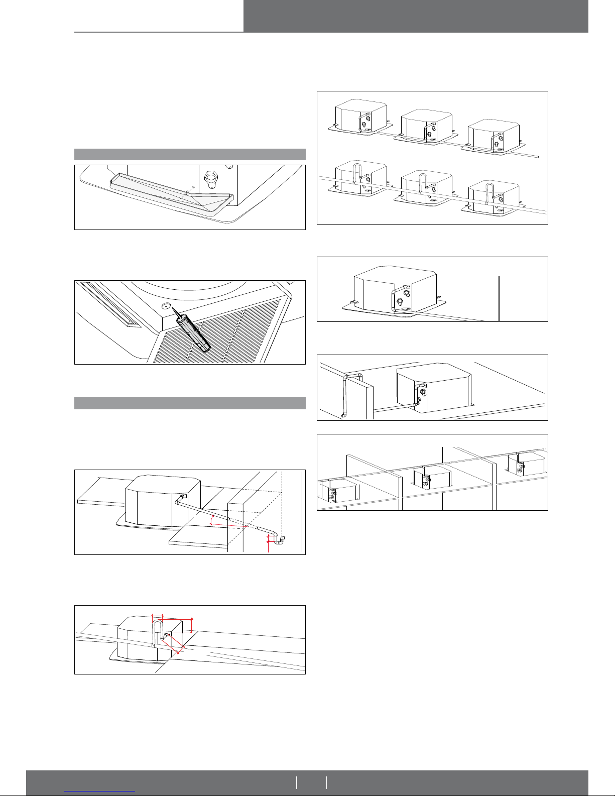
a) Remove the plastic cap from the condensate drain outlet on the water
cassette. Do NOT push the cap into the cassette.
Fit the nozzle into the hole (auxiliary condensate drain pan outlet).
b) Fix the auxiliary drain pan to the unit using the relative screws provided in the
kit, ensuring that the condensate pan is level.
IMPORTANT!
- If the drain pan plastic cap is removed, remember to seal it with silicone
when replacing it!
ATTENTION!
- Always use suitably sized wrenches to fi x or slacken the water pipes.
- It is essential to insulate pipes, valves and connections correctly in order
toavoid the formation of condensation, which could drip into suspended
ceilings causing considerable problems.
The water connections are fi xed to the unit body to avoid damage when pi-
pes are connected. It is advisable to tighten the connection with a wrench. The
upper coil connection is fi tted with an air valve and the lower connection with
a drain valve, suitable for a 10 mm wrench or screwdriver. (The coil is only
partially drainable; it is advisable to blow air into the coil for complete drainage)
The discharge levels in pic. 15 must be strictly adhered with.
The following diagrams describe some examples of how the condensate
discharge connection can be implemented correctly (Figs. 18-19) and incorrectly (Figs. 20-21).
Pic. 18: when several units are installed near to each other and only one condensate drain hose is used, make sure that the capacity of the hose is suffi cient
and that it is positioned on a slightly lower level than the appliance.
Pic. 19: the condensate drain hose should be fi xed using intermediate mounts
to prevent deformation of the hose. The drain hose should slope slightly downwards to encourage drainage of the condensed water.
Pic. 21: the drain hose is on the same lever as unit.
ATTENTION!
- Ultimately verify the smooth fl ow of condensate water from the basin to
the discharge pipe (before blocking the dropped ceiling)!
- If the condensate drainage alarm is activated, the zone valve is closed
and the fan turned off.
Pic. 20: the drain hose is bent or points upwards.
Pic. 14
Pic. 15
Pic. 18
Pic. 19
CORRECT!
CORRECT!
WRONG!
WRONG!
Pic. 16
Pic. 17
< 100 mm
< 200 mm
< 100 mm
Pic. 20
Pic. 21
Page 10
Vers. 2009-3
water cassettes
10
INSTALLATION, OPERATION
AND MAINTENANCE MANUAL
ELECTRICAL CONNECTIONS
ACCESS TO THE CONTROL PANEL
Pic. 23
ATTENTION!
Before carrying out electrical connections, ensure that the electricity
supply has been cut off, checking that the on-off switch is in the OFF
position.
Only qualifi ed electricians should carry out the electrical connections. Check
that the mains supply is single-phase 230 Vac/1/50 Hz (± 10%). Operating the
appliance with voltages outside the above limits could cause malfunction and
renders the warranty null and void.
The fan coil power supply line should be fi tted with at least a switch isolator in
conformity with European standard EN60947-3. Make sure that the electrical
system is suitable for providing not only the working current required by the
appliance, but also the necessary current for powering household and other
electrical appliances already in use. Any electrical and mechanical alterations
or tampering render the warranty null and void.
The motor and accessories power cables in channels or conduits should remain
inside the same until they are inside the appliances.
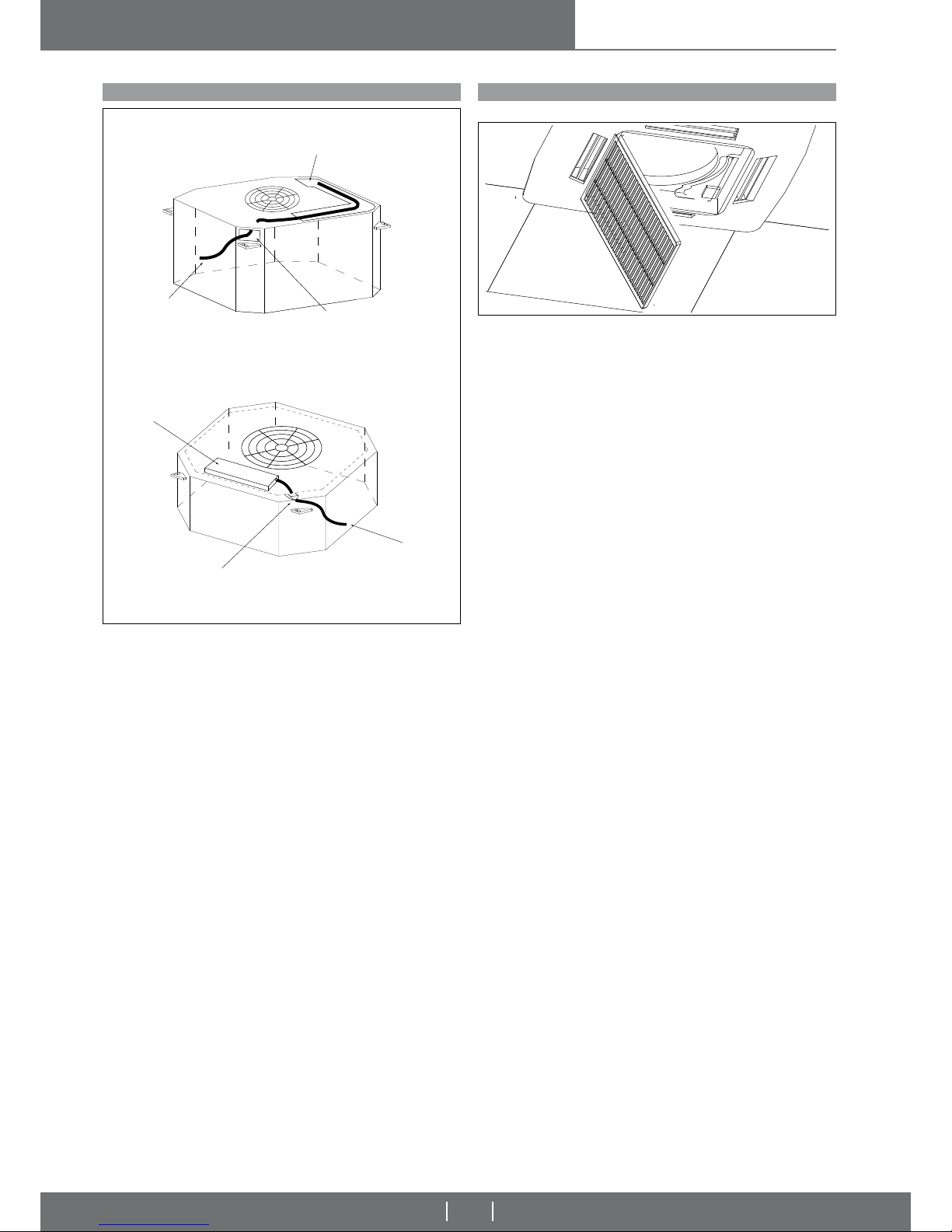
To access the switchboard, proceed as follows:
1 Open the cassette grille;
2 Remove the metal covers fi rst removing the screws;
3 Carry out the wiring;
4 Replace the metal covers and close the unit panel.
ELECTRIC POWER CABLES AND VALVES PASSAGE
Pic. 22
ELECTRICAL BOX
CABLE GLAND
ELECTRIC POWER
CABLE
ELECTRIC POWER
CABLE
PRESSACAVO
OPENING FOR
ELECTRIC POWER
CABLE PASSAGE
CS/4S
HC/4S
Page 11
Vers. 2009-3
water cassettes
11
INSTALLATION, OPERATION
AND MAINTENANCE MANUAL
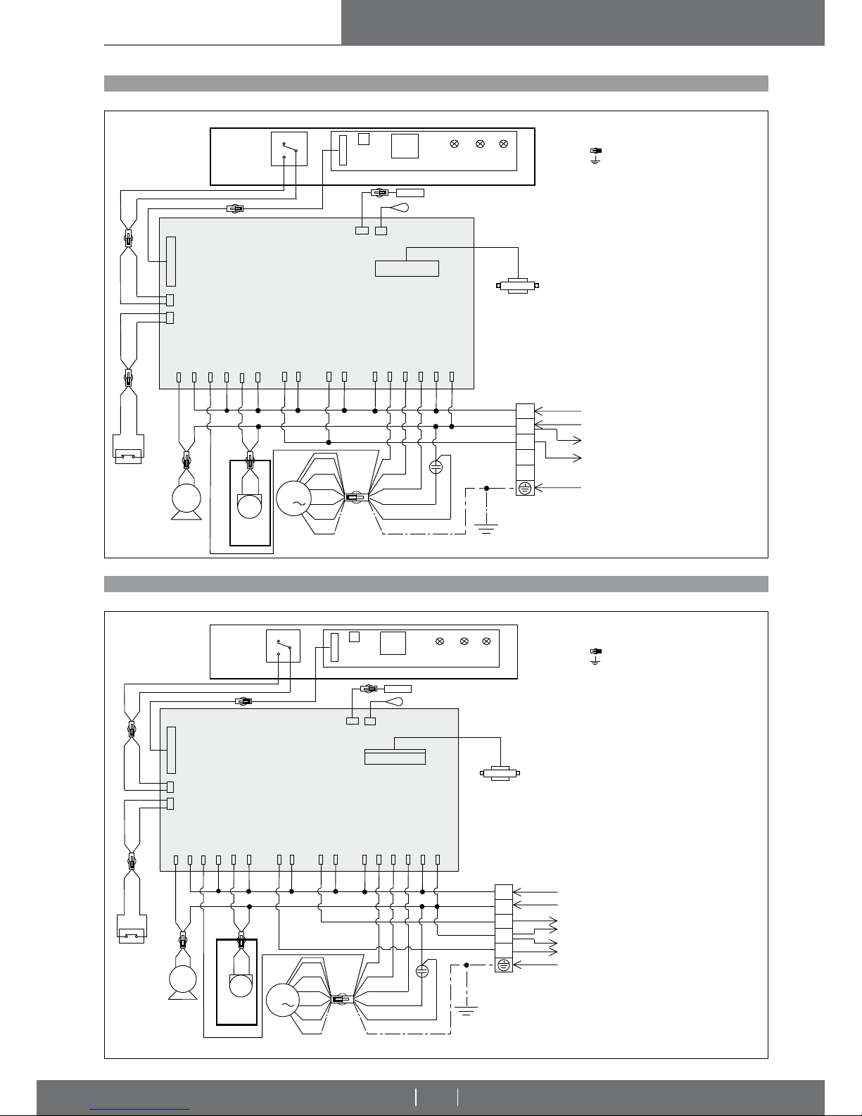
WIRING DIAGRAM OF 2 PIPE SYSTEM WATER CASSETTE WITH I.R. REMOTE CONTROL (CS/4S + HC/4S)
WIRING DIAGRAM OF 4 PIPE SYSTEM WATER CASSETTE WITH I.R. REMOTE CONTROL (CS/4S + HC/4S)
CASSETTES WITH A CONTROL BOARD THAT IS MANAGED ONBOARD
CASSETTES WITH A CONTROL BOARD THAT IS MANAGED ONBOARD
Pic. 24
Pic. 25
LEGENDA:
Connector
Earth
L Phase
N Neutral
M1 Fan motor (230Vac/50Hz)
SM Louver motor (230Vac/50Hz)
DP Drain pump (230Vac/50Hz)
FS Float switch (NC)
LS1 SM limit switch (60x60 cassette)
Safety switch (90x90 cassette: when
opening the fi lter panel, the unit wii stop)
Com Common
P1,P2,...,Pn Terminals
C3 Condenser
LEGENDA:
Connector
Earth
L Phase
N Neutral
M1 Fan motor (230Vac/50Hz)
SM Louver motor (230Vac/50Hz)
DP Drain pump (230Vac/50Hz)
FS Float switch (NC)
LS1 SM limit switch (60x60 cassette)
Safety switch (90x90 cassette: when
opening the fi lter panel, the unit wii stop)
Com Common
P1,P2,...,Pn Terminals
C3 Condenser
FS
P23
P18 P19
P20
P26P27
P25
P24
P11
P10
P8
P7
P6
P5
P4P3P2
P1
led led led
Timer Sleep Power
REC1
SW1
P1
LS1
NO
NC
DP
SM
M1
1
C3
P13
P12
P14
P15
L
N
L
N
C
ELECTRONIC
CONTROL BOARD
TRANSFORMER
TRANSFORMER
I.R. RECEIVER
I.R. RECEIVER
Electronic supply
230Vac/50Hz
Electronic supply
230Vac/50Hz
Heat/cool valve
230Vac/50Hz
Cool valve
230Vac/50Hz
Heat valve
230Vac/50Hz
Earth
Earth
WATER TEMPERATURE SENSOR
WATER TEMPERATURE SENSOR
AIR TEMPERATURE SENSOR
AIR TEMPERATURE SENSOR
FRONTAL
PANEL
FRONTAL
PANEL
TURBO
HIGH
MEDIUM
LOW
FRONTAL
PANEL
FRONTAL
PANEL
L
N
L
N
C1
P23
P18 P19
P20
P26P27
P25
P2
4
P1
3
P12
P11
P1
0
P8
P7
P6
P5
P4P3P2
P1
led led led
Timer Sleep Power
REC1
SW1
P1
LS1
NO
NC
DP
SM
N
C2
FS
M1
1
C3
P15
P14
ELECTRONIC
CONTROL BOARD
TURBO
HIGH
MEDIUM
LOW
Page 12
Vers. 2009-3
water cassettes
12
INSTALLATION, OPERATION
AND MAINTENANCE MANUAL
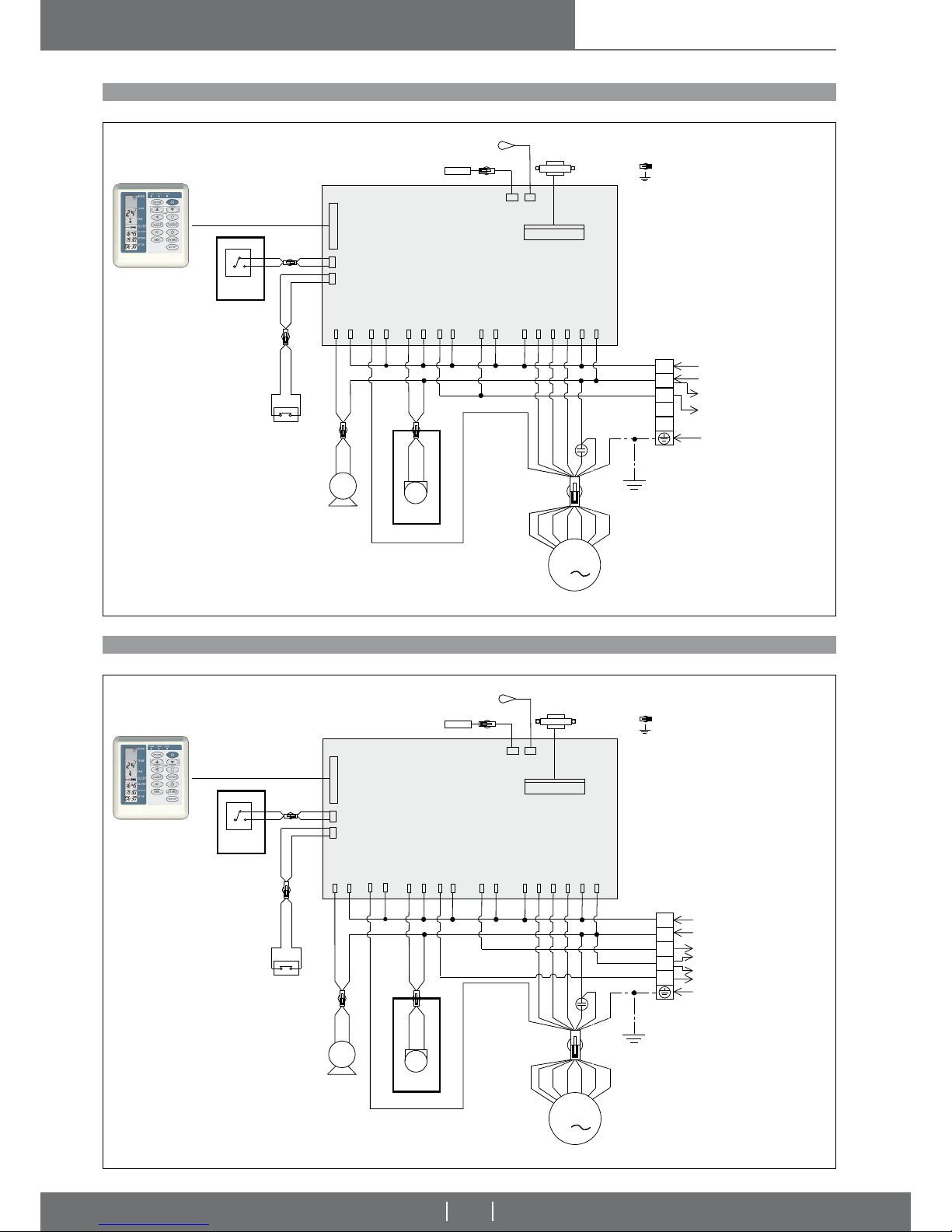
WIRING DIAGRAM OF 2 PIPE SYSTEM WATER CASSETTE WITH WALL MOUNTED CONTROL (CS/4S + HC/4S)
WIRING DIAGRAM OF 4 PIPE SYSTEM WATER CASSETTE WITH WALL MOUNTED CONTROL (CS/4S + HC/4S)
WALL MOUNTED CONTROL WITH THE SAME FUNCTIONS AS THE REMOTE CONTROL – CASSETTES WITH A CONTROL BOARD THAT IS MANAGED ONBOARD
WALL MOUNTED CONTROL WITH THE SAME FUNCTIONS AS THE REMOTE CONTROL – CASSETTES WITH A CONTROL BOARD THAT IS MANAGED ONBOARD
Pic. 26
Pic. 27
LEGENDA:
Connector
Earth
L Phase
N Neutral
M1 Fan motor (230Vac/50Hz)
SM Louver motor (230Vac/50Hz)
DP Drain pump (230Vac/50Hz)
FS Float switch (NC)
LS1 SM limit switch (60x60 cassette)
Safety switch (90x90 cassette: when
opening the fi lter panel, the unit will stop)
Com Common
P1,P2,...,Pn Terminals
C3 Condenser
LEGENDA:
Connector
Earth
L Phase
N Neutral
M1 Fan motor (230Vac/50Hz)
SM Louver motor (230Vac/50Hz)
DP Drain pump (230Vac/50Hz)
FS Float switch (NC)
LS1 SM limit switch (60x60 cassette)
Safety switch (90x90 cassette: when
opening the fi lter panel, the unit will stop)
Com Common
P1,P2,...,Pn Terminals
C3 Condenser
L
N
L
N
C
FS
P23
P18 P19
P20
P26P27
P25
P24
P13
P1
2
P11
P1
0
P8
P7
P6
P5P4P3
P2
P1
DP
SM
MODE
TEMP
POWER TIMER SLEEP COMP
SW
LV
HR
MIN
START
STOP
SLEEP
MODE
FAN
H
TEMP
COOL
SLEEP
SLEEP
CLOCK
START
STOP
LS1
NO
NC
M1
1
C3
P1
4
P1
5
TRANSFORMER
TRANSFORMER
Electronic supply
230Vac/50Hz
Electronic supply
230Vac/50Hz
Heat/cool valve
230Vac/50Hz
Cool valve
230Vac/50Hz
Heat valve
230Vac/50Hz
Earth
Earth
WATER TEMPERATURE SENSOR
WATER TEMPERATURE SENSOR
AIR TEMPERATURE SENSOR
AIR TEMPERATURE SENSOR
FRONTAL
PANEL
FRONTAL
PANEL
FRONTAL
PANEL
FRONTAL
PANEL
ELECTRONIC
CONTROL BOARD
OPTIONAL:
TEMPERATURE
CONTROLLER
OPTIONAL:
TEMPERATURE
CONTROLLER
TURBO
HIGH
MEDIUM
LOW
L
N
L
N
C1
P23
P18 P19
P20
P2
6P2
7
P25
P24
P13
P1
2
P11
P10
P8
P7
P6
P5P4P3
P2
P1
DP
SM
N
C2
FS
MODE
TEMP
POWER TIMER SLEEP COMP
SW
LV
HR
MIN
START
STOP
SLEEP
MODE
FAN
H
TEMP
COOL
SLEEP
SLEEP
CLOCK
START
STOP
LS1
NO
NC
M1
1
C3
P14P1
5
ELECTRONIC
CONTROL BOARD
TURBO
HIGH
MEDIUM
LOW
Page 13
Vers. 2009-3
water cassettes
13
INSTALLATION, OPERATION
AND MAINTENANCE MANUAL
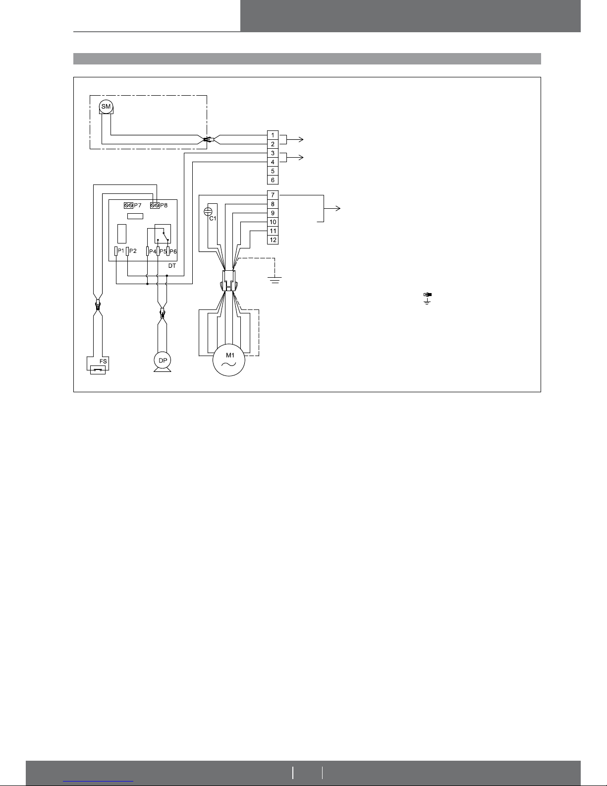
WIRING DIAGRAM OF 2/4 PIPE SYSTEM WATER CASSETTE FORESEEN FOR WALL MOUNTED CONTROL (CS/4S + HC/4S)
CASSETTES WITHOUT A CONTROL BOARD THAT IS MANAGED ONBOARD
Pic. 28
LEGENDA:
Connector
Earth
M1 Fan motor (230Vac/50Hz)
SM Louver motor (230Vac/50Hz)
DP Drain pump (230Vac/50Hz)
FS Float switch (NC)
DT Timer
C1 Condenser
FRONTAL
PANEL
Louver motor electrical supply
(230Vac/50Hz)
Permanent drain pump
electrical supply
(230Vac/50Hz)
Fan motor
electrical supply
(230Vca/50Hz)
Turbo
High speed
Med. speed
Min. speed
Com
Page 14
Vers. 2009-3
water cassettes
14
INSTALLATION, OPERATION
AND MAINTENANCE MANUAL
UNITS 2nd SERIES
UNITS 2
nd SERIES
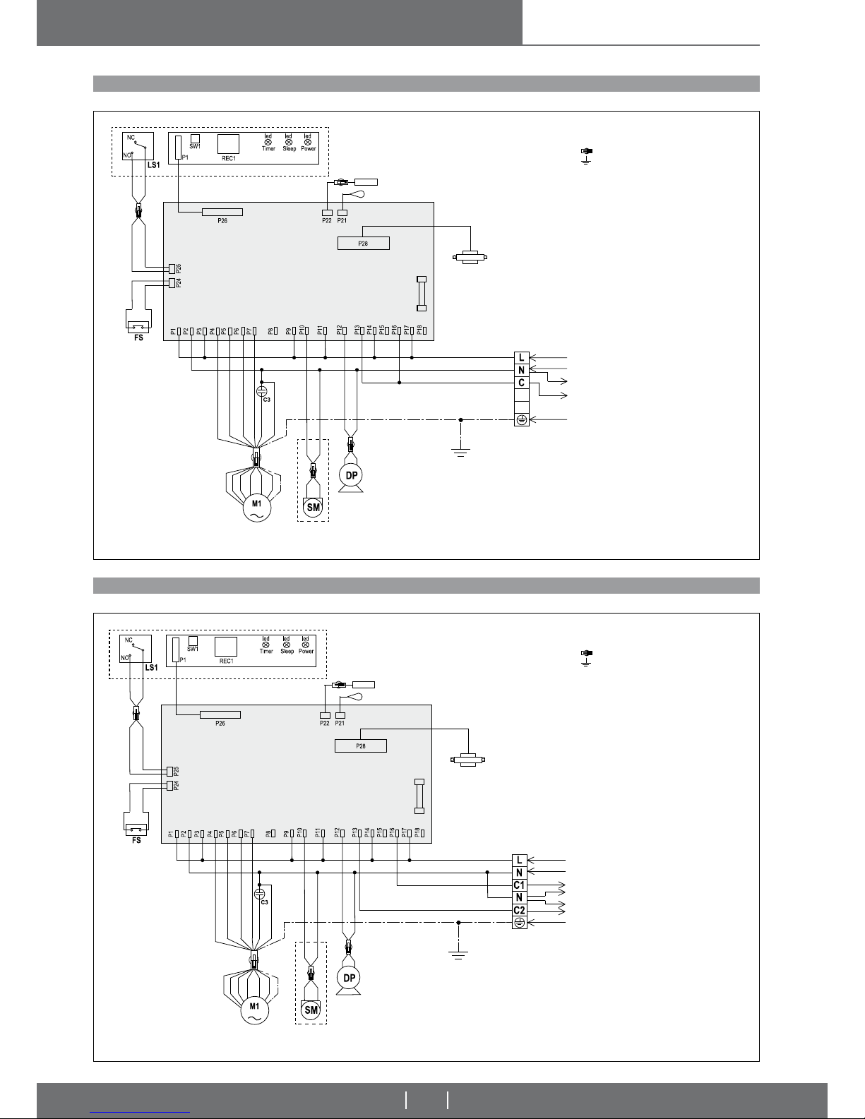
WIRING DIAGRAM OF 2 PIPE SYSTEM WATER CASSETTE WITH I.R. REMOTE CONTROL (CS/4S + HC/4S - 2nd SERIES)
WIRING DIAGRAM OF 4 PIPE SYSTEM WATER CASSETTE WITH I.R. REMOTE CONTROL (CS/4S + HC/4S - 2nd SERIES)
CASSETTES WITH A CONTROL BOARD THAT IS MANAGED ONBOARD
CASSETTES WITH A CONTROL BOARD THAT IS MANAGED ONBOARD
Pic. 29
Pic. 30
LEGENDA:
Connector
Earth
L Phase
N Neutral
M1 Fan motor (230Vac/50Hz)
SM Louver motor (230Vac/50Hz)
DP Drain pump (230Vac/50Hz)
FS Float switch (NC)
LS1 SM limit switch (60x60 cassette)
Safety switch (90x90 cassette: when
opening the fi lter panel, the unit wii stop)
Com Common
P1,P2,...,Pn Terminals
C3 Condenser
LEGENDA:
Connector
Earth
L Phase
N Neutral
M1 Fan motor (230Vac/50Hz)
SM Louver motor (230Vac/50Hz)
DP Drain pump (230Vac/50Hz)
FS Float switch (NC)
LS1 SM limit switch (60x60 cassette)
Safety switch (90x90 cassette: when
opening the fi lter panel, the unit wii stop)
Com Common
P1,P2,...,Pn Terminals
C3 Condenser
FRONTAL
PANEL
FUSE
FRONTAL
PANEL
TRANSFORMER
230-12 Vac
TRANSFORMER
230-12 Vac
I.R. RECEIVER
I.R. RECEIVER
Electronic supply
230Vac/50Hz
Heat/cool valve
230Vac/50Hz
Earth
WATER TEMPERATURE SENSOR
WATER TEMPERATURE SENSOR
AIR TEMPERATURE SENSOR
AIR TEMPERATURE SENSOR
TURBO
TURBO
HIGH
HIGH
MEDIUM
MEDIUM
LOW
LOW
FRONTAL
PANEL
FRONTAL
PANEL
ELECTRONIC
CONTROL BOARD
ELECTRONIC
CONTROL BOARD
FUSE
Electronic supply
230Vac/50Hz
Cool valve
230Vac/50Hz
Heat valve
230Vac/50Hz
Earth
Page 15
Vers. 2009-3
water cassettes
15
INSTALLATION, OPERATION
AND MAINTENANCE MANUAL
UNITS 2nd SERIES
UNITS 2
nd SERIES
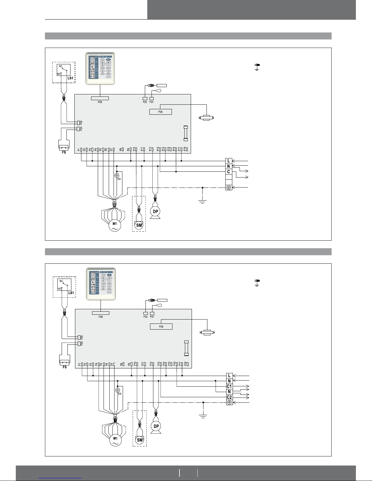
WIRING DIAGRAM OF 2 PIPE SYSTEM WATER CASSETTE WITH WALL MOUNTED CONTROL (CS/4S + HC/4S - 2nd SERIES)
WIRING DIAGRAM OF 4 PIPE SYSTEM WATER CASSETTE WITH WALL MOUNTED CONTROL (CS/4S + HC/4S - 2nd SERIES)
WALL MOUNTED CONTROL WITH THE SAME FUNCTIONS AS THE REMOTE CONTROL – CASSETTES WITH A CONTROL BOARD THAT IS MANAGED ONBOARD
WALL MOUNTED CONTROL WITH THE SAME FUNCTIONS AS THE REMOTE CONTROL – CASSETTES WITH A CONTROL BOARD THAT IS MANAGED ONBOARD
Pic. 31
Pic. 32
LEGENDA:
Connector
Earth
L Phase
N Neutral
M1 Fan motor (230Vac/50Hz)
SM Louver motor (230Vac/50Hz)
DP Drain pump (230Vac/50Hz)
FS Float switch (NC)
LS1 SM limit switch (60x60 cassette)
Safety switch (90x90 cassette: when
opening the fi lter panel, the unit will stop)
Com Common
P1,P2,...,Pn Terminals
C3 Condenser
LEGENDA:
Connector
Earth
L Phase
N Neutral
M1 Fan motor (230Vac/50Hz)
SM Louver motor (230Vac/50Hz)
DP Drain pump (230Vac/50Hz)
FS Float switch (NC)
LS1 SM limit switch (60x60 cassette)
Safety switch (90x90 cassette: when
opening the fi lter panel, the unit will stop)
Com Common
P1,P2,...,Pn Terminals
C3 Condenser
FUSE
FUSE
TRANSFORMER
230-12 Vac
TRANSFORMER
230-12 Vac
WATER TEMPERATURE SENSOR
WATER TEMPERATURE SENSOR
AIR TEMPERATURE SENSOR
AIR TEMPERATURE SENSOR
TURBO
TURBO
HIGH
HIGH
MEDIUM
MEDIUM
LOW
LOW
FRONTAL
PANEL
FRONTAL
PANEL
FRONTAL
PANEL
FRONTAL
PANEL
ELECTRONIC
CONTROL BOARD
ELECTRONIC
CONTROL BOARD
Electronic supply
230Vac/50Hz
Heat/cool valve
230Vac/50Hz
Earth
Electronic supply
230Vac/50Hz
Cool valve
230Vac/50Hz
Heat valve
230Vac/50Hz
Earth
Page 16

Vers. 2009-3
water cassettes
16
INSTALLATION, OPERATION
AND MAINTENANCE MANUAL
SECOND PART:
FOR THE USER
Page 17
Vers. 2009-3
water cassettes
17
INSTALLATION, OPERATION
AND MAINTENANCE MANUAL
T
U
RB
O
S
E
N
D
O
N
E
CO
N
O
MO
DE
S
L
E
E
P
D
I
M
O
F
F
TU
R
B
O
S
E
N
D
O
N
ECONO
MO
DE
S
L
E
E
P
D
I
M
O
F
F
T
UR
B
O
S
E
N
D
O
N
E
CO
N
O
MO
DE
S
L
E
E
P
D
I
M
O
F
F
RESETCLOCK
_
+
_
+
1,5 V
1,5 V
RECCOMENDATION WATER CASSETTE OPERATION
THE INFRARED REMOTE CONTROLLER
Read the precautions carefully and carry out the procedures correctly:
- In case of failure or malfunction, always apply to authorised service personnel. Any attempt to remove parts, or to maintain the appliance can expose
the user to danger of electrical shock. The cassette does not contain parts on
which maintenance can be carried out by the user.
- In case of relocation, apply to service personnel authorised to carry out
this operation as well as the new installation.
- Do not insert fi ngers or objects of any kind into airfl ow outlets or air in-
take grilles. There is a fan inside the appliance, which turns at high speed and
could cause severe personal injury. Pay particular attention to children.
- Do not allow the cold airfl ow to blow on you directly for long periods
of time. Direct and prolonged exposure to cold air can be dangerous for your
health. Pay particular attention to rooms where there are children, elderly or
sick people.
- In case of air conditioner malfunction (e.g. smell of burning), stop appliance operation immediately, release the dedicated automatic switch
and apply to authorised service personnel. Prolonged use of the appliance
in these conditions can cause fi re or electrocution.
- During installation of the appliances, avoid letting children or disabled
have access to the working area. Accidents can occur.
- Install the appliance and the remote control at least two metres away
from television or radio units and from lamps that could irradiate them
directly. Any interference of radio signals can cause operating problems.
- Do not block or cover the airfl ow intake and delivery grilles. The obstruc-
tion of these openings causes a reduction of the operating effi ciency of the
water cassette, with consequent possible failure or damage.
- Do not use the water cassette for applications such as the storage of
foods, plants, precision equipment or works of art. The quality of the objects
that are stored could deteriorate.
- Do not expose animals or plants to the direct airfl ow from the appliance.
Prolonged direct exposure to the cold airfl ow from the water cassette can have
a negative effect on animals and plants.
- Do not direct the airfl ow of the air conditioner towards fi replaces or other
heating appliances. An airfl ow directed towards the fi re can cause incorrect
combustion and fi re.
- Air the room occasionally while using the appliance. An insuffi cient chan-
ge of air can cause an insuffi ciency of oxygen in the room.
- Do not allow the air conditioner to come into contact with water. The
electrical insulation could be damaged with consequent possible risk of electrocution.
- Check installation conditions in order to identify possible damage.
After prolonged use, apply to specialised service personnel to control the installation conditions of the air conditioner.
- Do not use fl ammable gas near the air conditioner.
- Always use the appliance with the air fi lter installed.
Using the air conditioner without the air fi lter can cause an excessive accumu-
lation of dust or deposits inside the unit, with consequent possible malfunctioning.
- Release the “automatic” switch if the unit is not going to be used for long
periods of time.
- Remove the batteries from the remote control if it is not going to be used
for a long period of time. Remove the batteries in order to prevent possible
problems caused by loss of electrolyte. In case of accidental contact of the battery liquid with the skin, eyes or mouth, wash the affected part immediately with
plenty of water, and see a doctor.
- Please shut off the unit ONLY using the ON/OFF switch
(infrared or
wall-mounted remote control).
FAILURE TO COMPLY WITH THE INSTALLATION INSTRUCTIONS GIVEN
IN THIS MANUAL RELIEVES THE MANUFACTURER OF ALL AND ANY LIABILITY. INCORRECT INSTALLATION COULD CAUSE MALFUNCTIONING
OR FAILURE OF THE APPLIANCE.
IT COULD ALSO REPRESENT A HAZARD FOR THE USER.
The water cassette has been designed to create the ideal climatic conditions for
the comfort of the occupants of the room. It can provide fully automatic cooling,
dehumidifying and also heating. The air is drawn in by the fan through the intake
grille in the front panel and then passes through the fi lter, which retains the dust.
The air then proceeds through the fi ns of a “heat exchanger”: this is a fi nned
coil, which cools and dries or heats the air. Finally the fan sends the air into
the room; the direction of the outgoing airfl ow can be adjusted by means of the
motor-driven direction louver.
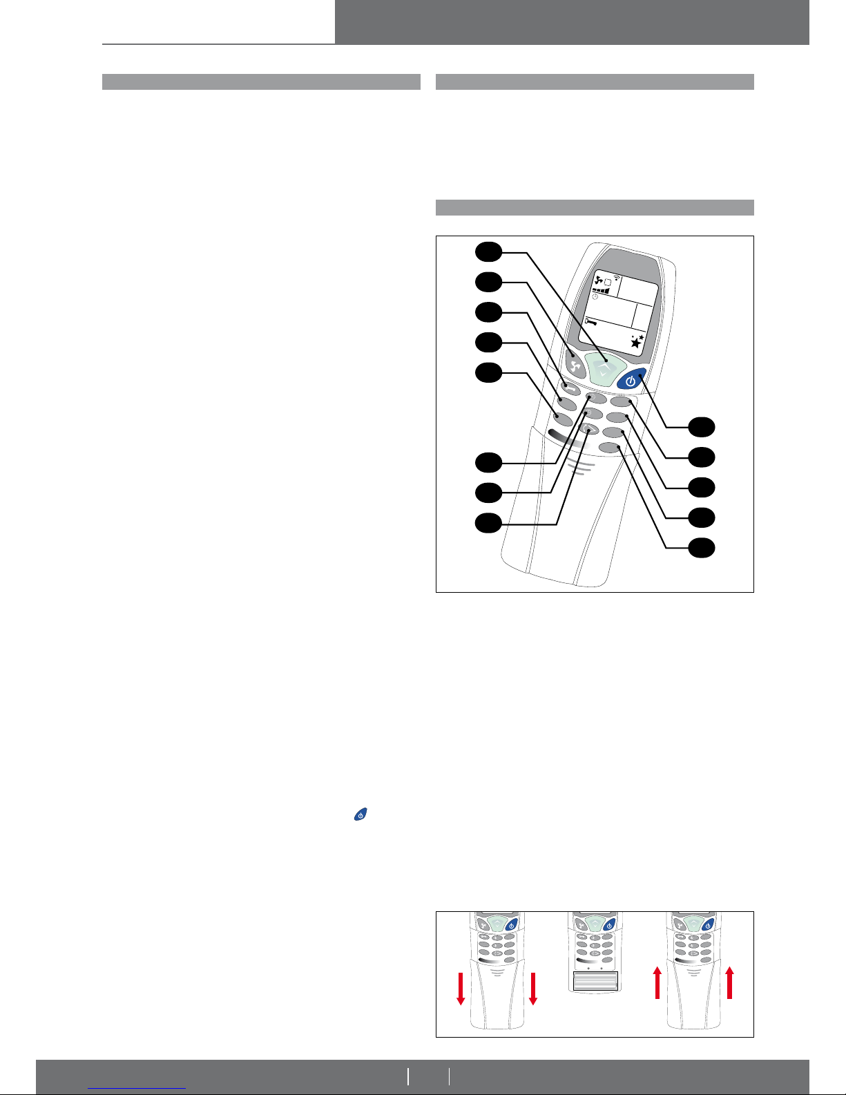
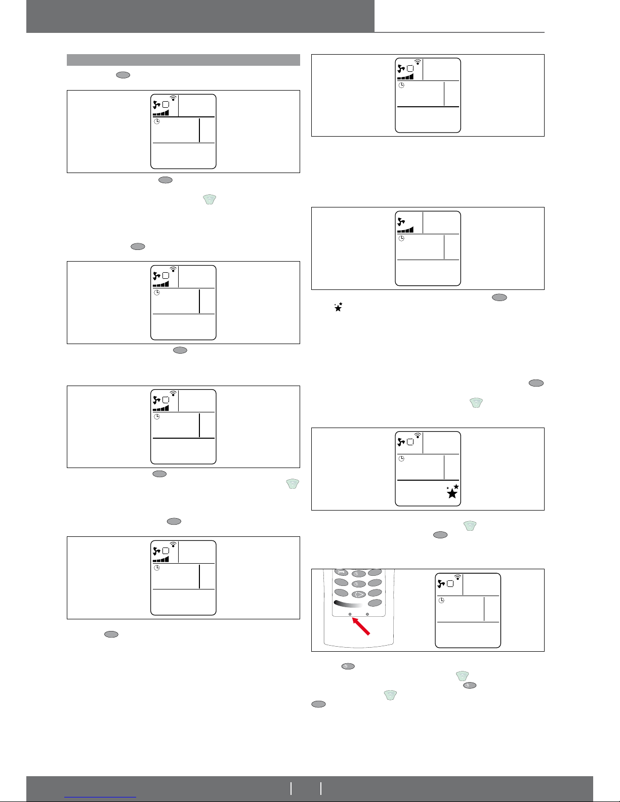
1
Select the desired room temperature (18 °C to 30 °C) and adjust the hours/minutes
2 Select the fan speed (4 positions + automatic)
3 Lock function: when kept pressed for 5 seconds, the remote control is blocked
4 TURBO function: it warms or cools for 30 min at the maximum speed
5 Sends all the settings that are in the remote control at that moment
6 Daily timer On
7 Daily timer Off
8 Enables or disables the movement of the vents
9 Turns the unit on or off
10 Economy function: automatic fan
heating: 20 °C - cooling: 25 °C
11 Function mode:
Cool = cooling; Heat = warming; Fan = only ventilation
Auto = only for units with 4 pipes (cooling and heating)
12 Night function:
13 Not used
The unit gives a beep to confi rm that it has received each button com-
mand correctly.
Replacing the batteries. When no acoustic signal is emitted from the unit or
the LCD display does not go on, pull the cover downwards as shown in the
diagram at the side (2 batteries AAA 1.5 V). Insert the new batteries observing
their polarity.
ATTENTION: only use new batteries. Remove the batteries from the remote control when the water cassette is not used.
CASSETTE WITH A CONTROL BOARD THAT IS MANAGED ONBOARD
Pic. 33
Pic. 34
A
FA
N
C
O
O
L
T
U
R
B
O
E
C
O
N
O
DRY
H
E
AT
A
U
TO
2
0
c
°
0
:
0
0
A
I
R
C
O
N
D
.
O
N
O
F
F
0
:
0
0
T
URB
O
S
E
N
D
O
N
E
C
O
N
O
M
O
D
E
S
L
E
E
P
D
I
M
O
F
F
5
4
3
2
1
9
10
11
12
13
7
6
8
Page 18
Vers. 2009-3
water cassettes
18
INSTALLATION, OPERATION
AND MAINTENANCE MANUAL
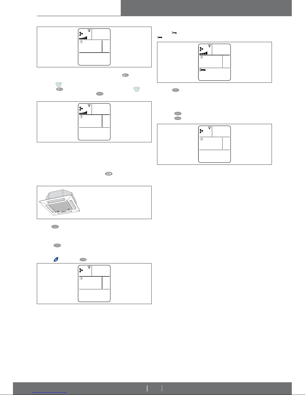
I.R. REMOTE CONTROL OPERATIONS
FAN When the
M
O
D
E
button is pressed and the FAN mode is selected, the
cassette will operate as an electrical fan only.
COOLING (COOL) When the
M
O
D
E
button is pressed and COOL is selected,
the cassette cools the room and at the same time reduces the humidity in the
air. To start the cooling cycle, use the button
to set a temperature which
is lower than the room temperature. For example: if there is a temperature of
28°C in the room, a temperature lower than 27°C should be set in order for the
compressor and cooling to start. The appliance automatically adjusts operating
cycles in order to keep the room at the required temperature. Upon completion
of settings, press the
S
E
N
D
button and listen for the beep to make sure that the
appliance has received the command.
FAN SPEED ADJUSTMENT (FAN)
When the FAN button is pressed, one of the
following fan speeds can be selected: AUTO - MINIMUM - AVERAGE - MAXIMUM
- TURBO
In the AUTO mode, the electronic control automatically selects the fan speed according to the difference between the set temperature and the room temperature.
This function automatically increases the fan speed if a greater cooling or heating
effect is required.
SLEEP MODE (SLEEP) Access this mode by pressing the
S
L
E
E
P
button. The
symbol
will appear on the display, as shown in the drawing to the side.
The SLEEP mode automatically adjusts the temperature to make the sleeping
environment more comfortable during the night. During the cooling or dehumidifying modes the set temperature is increased gradually by 2°C during the fi rst
two hours of operation. During the heating mode the set temperature is decreased gradually by 2°C during the fi rst 2 hours of operation. Timed switching off
can also be set together with the SLEEP mode.
Note:
- When the system is set to SLEEP mode, this will be cancelled when the
S
L
E
E
P
key is pressed;
- When the system is set to SLEEP mode and the
key is pressed, the
previously set temperature will be increased by 1 °C;
- The SLEEP function will be cancelled if there is a power failure.
SETTING THE CLOCK Press the CLOCK key and the corresponding part on
the display will fl ash: the current time is set via the
key. Once this is com-
pleted, confi rm the time by pressing the
S
E
N
D
key and the acoustic signal will
verify that the correct signal has been received.
IMPORTANT: Before setting timed switching on, set the required operating
mode and fan speed. Then switch the air conditioner off.
TIMED SWITCHING ON To set timed switching on, the appliance must be off.
Press the
O
N
button and the corresponding part of the display starts to blink.
Set the time for timed switching on using the
button. The subsequent
switching off time may also be set by pressing the
O
F
F
button and setting the
required time using the
button. Confi rm the new setting by pressing the
S
E
N
D
button and listen for the beep to make sure that the appliance has received
the signal.
DEHUMIDIFYING (DRY) When the
M
O
D
E
button is pressed and the DRY mode
selected, the cassette alternates cooling and fan cycles. This mode is used to
dehumidify the air without excessively altering the room temperature.
Operation is fully automatic: the appliance itself controls the fan speed
HEATING (HEAT) When the
M
O
D
E
button is pressed and the HEAT mode is se-
lected, the cassette will heat the room. To start the heating cycle, use the
button and to set a temperature which is higher than the room temperature. For
example: if there is a temperature of 18°C in the room, a temperature higher
than 19°C should be set in order for the compressor and heating to start. Upon
completion of settings, press the
S
E
N
D
button and listen for the beep to make
sure that the appliance has received the command.
AUTOMATIC MODE (AUTO) only for units with 4 pipes. Access this mode by
pressing the
M
O
D
E
button. In the AUTO mode the electronic control automatically
selects the operating mode according to the room temperature (measured by
the built-in sensor):
- if the room temperature drops below 18°C, the appliance will start the heating
cycle. This will continue until the temperature rises to above 20°C;
- if the room temperature is above 26°C the appliance will start the cooling cycle.
This will continue until the temperature drops below 24°C.
Pic. 35
Pic. 39
Pic. 40
Pic. 41
Pic. 42
Pic. 36
Pic. 37
Pic. 38
A
FAN
c
°
0:00
A
COOL
20
c
°
0:00
A
DRY
20
c
°
0:00
A
HEAT
20
c
°
0:00
A
AUTO
20
c
°
0:00
FAN
c
°
0:00
A
COOL
20
c
°
0:00
T
U
R
B
O
S
E
N
D
O
N
E
C
O
N
O
M
O
D
E
S
L
E
E
P
D
I
M
O
F
F
RESETCLOCK
A
COOL
20
c
°
12:57
Page 19
Vers. 2009-3
water cassettes
19
INSTALLATION, OPERATION
AND MAINTENANCE MANUAL
TIMED SWITCHING OFF To set timed switching off, the appliance must be on
or the timed switching on function must be set. Press the
O
F
F
button and the
corresponding part of the display starts to blink. Set the time for timed switching
off using the
button. The subsequent switching on time may also be set by
pressing the
O
N
button and setting the required time using the button.
Confi rm the new setting by pressing the
S
E
N
D
button and listen for the beep to
make sure that the appliance has received the signal.
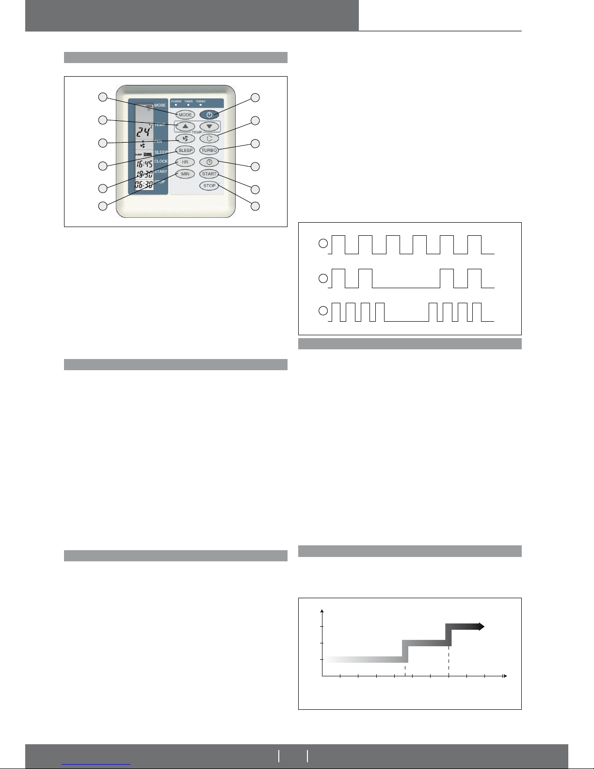
TURBO FUNCTION
Press the
T
U
R
B
O
key in cooling, heating or automatic mode. The fan temperature
and speed will disappear from the remote control display. The TURBO function
activates the fan (heating or cooling mode) at maximum speed for 30 minutes.
The TURBO function is deactivated:
• Press the
T
U
R
B
O
key again while the function is active.
• The room temperature will reach 18 °C in cooling mode or 30 °C in heating
mode.
• Press the
(on/off) or the
M
O
D
E
(operating mode) key.
BLOCKING THE REMOTE CONTROL
Keep the key pressed for 2 seconds to block the remote control. Keep the
key pressed for 2 seconds to unblock the remote control.
ECONO
Press the
E
C
O
N
O
key in cooling, heating or automatic mode to activate the energy
saving mode. The fan temperature and speed will disappear from the remote
control display.
The temperature is set at 25 °C in cooling mode and 20 °C in heating mode.
The ECONO function is deactivated:
• Press the
E
C
O
N
O
key again while the function is active.
• Press the
M
O
D
E
(operating mode) key.
Note:
The timed shutdown function will be cancelled if there is a power failure.
WARNING!
Once the switch on and/or the switch off time is expired, it will be automatically canceled from the internal memory. Switch on and switch off time
need to be setted each time the user necessitate.
ADJUSTING THE AIR FLOW By means of the
key the louvres are activated and deactivated so that the air fl ow is directed alternatively downwards and
upwards and the air is evenly emitted in the room.
WARNING!
DO NOT POSITION THE LOUVERS MANUALLY AS THIS MAY
DAMAGE THE DELICATE MECHANISM THAT MOVES THEM.
Pic. 43
Pic. 44
Pic. 46
Pic. 47
Pic. 48
Pic. 45
O
N
O
F
F
COOL
20
c
°
0:00
AIR COND.
ON
COOL
20
c
°
AIR COND.
OFF
0:00
COOL
TURBO
c
°
0:00
COOL
20
c
°
0:00
COOL
ECONO
c
°
0:00
Page 20
Vers. 2009-3
water cassettes
20
INSTALLATION, OPERATION
AND MAINTENANCE MANUAL
to the valve output.
Remedy: check the coil water temperature and correct valve operation.
c) The incorrect mode has been set:
- there is hot water when the mode is set on cooling;
- there is cold water when the mode is set on heating;
4) TIMER indicator light blinks continuously (Pic. 50A):
Air temperature sensor and water temperature sensor are damaged or not connected.
5) TIMER indicator light blinks intermittently (Pic. 50B): the fi lters must
be cleaned.
When the cassette has been operating for more than 500 hours, a warning is
displayed as a reminder to clean the fi lter.
6) The POWER indicator fl ashes intermittently (Pic. 50 C).
Only for cassettes HC4S.
Safety switch (LS1) open.
ATTENTION: reset by cutting off the power for at least 10 seconds. Una
volta ridata tensione l’unità rientra in allarme se dopo 3 minuti questo stato persiste. Once the power returns the unit will return to the alarm status
if this persists after 3 minutes.
Pic. 51
Set
FAN SPEED
COIL TEMPERATURE [Ti]
slow
OFF
CONDENSATE DRAIN PUMP OPERATION SPECIFICATIONS
PRE-HEATING FUNCTION
CASSETTE WITH A CONTROL BOARD THAT IS MANAGED ONBOARD
Cool - The unit is running: the pump is always on until the set temperature is
reached.
The unit is turned off from the remote control or the set temperature has been
reached: when the water reaches the fl oat, the contact is opened and the pump
is activated for 3 minutes; after which, if the fl oat does not close the contact
once again (water discharge), the unit will enter an alarm status.
Dry - cool.
Heat - The unit is running or was turned off from the remote control: the pump
is activated by the fl oat.
Fan - heat.
Auto
If the unit is in the cool mode, the pump follows the cool operation.
If the unit is in the heat mode, the pump follows the heat operation.
CASSETTE WITHOUT A CONTROL BOARD THAT IS MANAGED ONBOARD
The condensate discharge pump is activated when the water level inside the
main condensation basin reaches the fl oat and opens its contact. A timer acti-
vates the condensate discharge pump for about 3 minutes (empty-basin cycle),
which is repeated until the fl oat’s contact is closed.
No discharge condensate alarms are foreseen.
CASSETTE WITH A CONTROL BOARD THAT IS MANAGED ONBOARD
Pre-heating function is used to avoid cold air in HEAT mode when the valve is
open. The valve remains open also if within 3 minutes the coil temperature has
not reached the 35°C.
0510 3015 20 25 35 40 45 5023 °C
Pic. 49
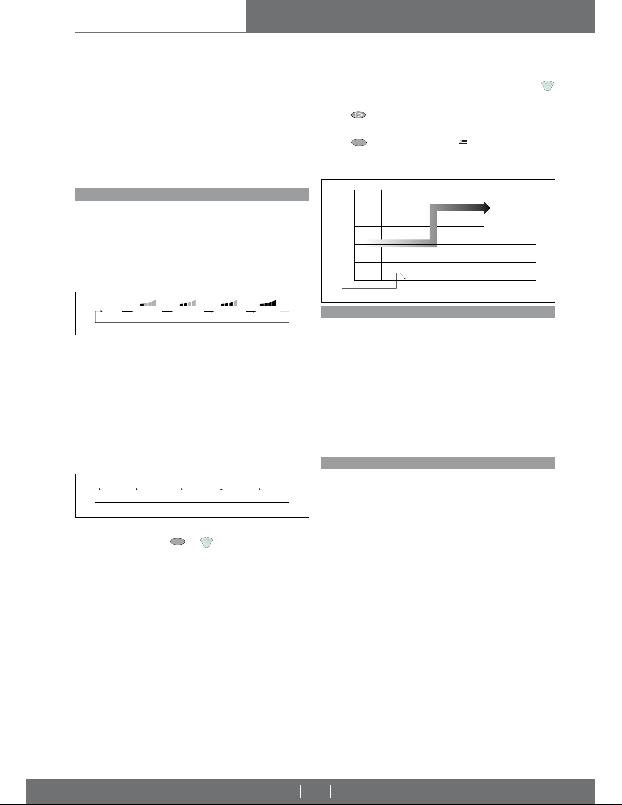
WALL MOUNTED CONTROL – SAME FUNCTIONS AS THE REMOTE CONTROL
WALL-MOUNTED CONTROL OPERATIONS
TROUBLESHOOTING
CASSETTE WITH A CONTROL BOARD THAT IS MANAGED ONBOARD
CASSETTE WITH A CONTROL BOARD THAT IS MANAGED ONBOARD
1 Function mode: Cool = cooling; Heat = warming; Fan = only ventilation;
Auto = only for units with 4 pipes (cooling and heating).
2 Select the desired room temperature (18 °C to 30 °C)
3 Select the fan speed (4 positions + automatic)
4 Night function:
5 Setting the hour.
6 Setting the minutes.
7 Turns the unit on or off
8 Enables or disables the movement of the vents
9 Turbo function: warms or cools for 30 min at the maximum speed
10 Setting the current time.
11 Daily timer on
12 Daily timer off
Refer to the I.R. remote control to learn the functions
Self-diagnosis
The system comes with a self-diagnosis circuit to monitor the microprocessor
functions. In the event of malfunction this circuit automatically resets the microprocessor.
System memory
The system stores the set parameters (such as the operating status, fan speed,
etc.) in its non-volatile storage. After a power failure, the cassette will automatically resume operation with the same parameters that were set prior to
the blackout (except the SLEEP and TIMER modes which will be erased). Any
change to the parameters will be saved in the non-volatile storage after 5 seconds.
Situation of normal operation
The POWER indicator light is on if the cassette was switched on via the I.R.
remote control.
The TIMER indicator light is on if the AUTO START and AUTO STOP modes
are active.
The SLEEP indicator light shows the temperature compensation during the
SLEEP mode.
1) The POWER, SLEEP and TIMER indicator lights blink continuously: The
system is protected by the cutting off of power to all the outputs.
This type of alarm is generated by one events:
- safety fl oat with an always open contact (the main condensation basin is full
of water).
Remedy: check the condensate drainage circuit (pump, fl oat, drain hoses):
inclination and height.
2) The SLEEP indicator lights blink continuously (Pic. 50A):
- Coil water temperature above 80 °C.
Remedy: check coil water temperature.
3) The POWER indicator fl ashes intermittently (Pic. 50 B).
This type of alarm can be caused by three events:
a) When 3 minutes have elapsed from the start of the COOL or DRY cycles, coil
temperature is above 25° C. The system is protected by the cutting off of power
to the valve output.
Remedy: check the coil water temperature and correct valve operation.
b) When 3 minutes have elapsed from the start of the HEAT cycle, coil temperature is not above 20° C. The system is protected by the cutting off of power
7
8
9
10
11
12
1
2
3
4
5
6
Fig. 50
ON
OFF
B
ON
OFF
A
ON
OFF
C
Page 21
Vers. 2009-3
water cassettes
21
INSTALLATION, OPERATION
AND MAINTENANCE MANUAL
If Ti < 23°C, fan is OFF.
If 23 < Ti < 35°C, fan runs at minimum speed
If Ti > 35°C, fan runs at setted speed.
ELECTRICAL CHARACTERISTICS
- Power supply 1Ph from 185 to 255 VAC, 50/60Hz
- Power consumption Less than 8 VA in stand-by
- Valve activation time delay 3 minutes ± 5 seconds
Temperature:
- Room temperature accuracy ±1°C
- Coil temperature accuracy ±2°C
- Storage temperature 0÷70°C
- Operating temperature 10÷70°C
- Setting temperature range 18÷30°C (+1°C step)
- ON/OFF temperature differential 1°C
Pic. 52
Pic. 53
OPERATING DETAIL
CASSETTE WITH A CONTROL BOARD THAT IS MANAGED ONBOARD
The following commands be given by the buttons on the eall-mounted control.
Switching on/off
Press the POWER button to switch the cassette on or off. When the system has
been switched on, it will operate according to the settings shown on the display.
The POWER indicator light on the display comes on.
Fan
Press the FAN button to select the fan speed (high, medium, low or auto mode).
The display instantly shows the operating status.
Auto mode
When the fan speed is set in the AUTO mode, the speed is adjusted automatically according to the difference between the room temperature and the set
temperature:
- If the difference is 3°C or more, the speed is HIGH;
- If the difference is 2°C, the speed is MEDIUM;
- If the difference is 1°C or less, the speed is LOW.
Function mode:
- Ventilation (FAN)
- Air-conditioning (COOL)
- Dehumidifying (DRY)
- Heating (HEAT)
- Automatic (AUTO)
FAN
The writing FAN appears on the air-conditioner control display. In this mode the
unit operates as a fan only. The
S
L
E
E
P
and buttons are not used.
COOL
The writing COOL appears on the air-conditioner control display. The unit operates in the air-conditioning mode.
- the zone valve starts if Troom ≥ Tset+1
- the zone valve stops if Troom ≤ Tset
In any case activation of the zone valve is subject to 3 minutes delay each time
it stops.
DRY
The writing DRY appears on the air-conditioner control display. The unit operates in the dehumidifying mode to reduce the percentage of humidity in the
room.
HEAT
The writing HEAT appears on the air-conditioner control display. The unit operates in the air-conditioning mode.
- the zone valve starts if Troom ≤ Tset -1
- the zone valve stops if Troom ≥ Tset
In any case activation of the zone valve is subject to 3 minutes delay each time
it stops.
FAN COOL DRY HEAT AUTO
Pic. 54
HOURS
START SLEEP MODE
ROOM TEMPERATURE
Increase of 1°C
after 1 hour
COOLING
TIPS FOR BEST USE
ENERGY SAVING
AUTO
The writings COOL and HEAT appear on the display simultaneously.
Temperature setting
The setting temperature can be set in the range of 18°C-30°C by pressing
button. The LCD on the display unit will show the setting temperature.
Louver swing
Press the
button to start/stop louver swing.
SLEEP mode
Press the
S
L
E
E
P
key to activate the mode. The symbol will appear on the display. In cool air-conditioning mode, the temperature is automatically increased
by 1 °C after an hour. Similarly, in warm air-conditioning mode the temperature
is decreased by 1 °C after an hour.
- Connect the cassette to a dedicated power socket protected by a magnetothermal circuit breaker of suitable capacity for the electrical input of the appliance.
- When the water cassette starts or stops, especially in the heating mode, creaking sounds may be heard. This is caused by thermal expansion of the unit
parts.
- Mist may sometimes be produced by the cassette for a few seconds in the cooling mode. This is quite normal and is caused by the difference in temperature
between the air fl owing out of the appliance and the air in the room.
- Do not place heat sources near to the cassette as this could deform the plastic
parts.
- Do not insert objects into the air intakes or outlets when the cassette is in
operation.
- Do not place objects in a position that may obstruct the passage of the air into
the unit as this could affect appliance effi ciency.
- Avoid opening and closing doors and windows: the continuous thermal transfer
hinders the unit’s production.
- Do not set a temperature that is too high (in heating mode) or too low (in
cooling mode).
- Avoid installing the unit where it is directly exposed to sunlight.
- Use the timed shutdown to prevent it from being left on unnecessarily.
- Use the SLEEP function during the night.
20.0
22.0
012
AUTO MINIMUM MAXIMUMAVERAGE TURBO
Page 22
INSTALLATION, OPERATION
AND MAINTENANCE MANUAL
Vers. 2009-3
22
ROUTINE MAINTENANCE
ATTENTION!
Turn off the automatic circuit breaker before carrying out any cleaning
operations. Use a cloth dampened with lukewarm water (max 40°C)
and mild detergent to clean the cassette. Do not use solvents or harsh
detergents.
OPENING THE PANEL
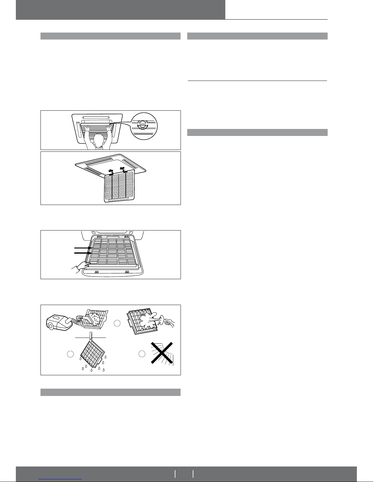
To open the grille turn the plastic screws present on the grille by 90° (1/4 of a
turn) (pic. 55) and gently pull the panel downwards without forcing the hinges
that fasten it to the appliance. Attention: to make cleaning easier, the grille may
be removed completely since the receiver panel is positioned on the fi xed frame
of the unit (see pic. 56).
FILTER CLEANING
Filter cleaning is essential for the good appliance effi ciency.
1) Remove the fi lters by pulling them gently sideways and pressing lightly on the
points shown in Pic. 57.
2) Clean the fi lters with a vacuum cleaner or wash them with lukewarm water
and mild detergent.
3) Make sure the fi lters are dry before replacing them in the appliance.
4) Do not expose the fi lters to sunlight.
NB!
NEVER OPERATE THE CASSETTE WITHOUT THE AIR FILTERS!
Pic. 55
Pic. 56
Pic. 57
Pic. 58
4
3
2
END OF SEASON MAINTENANCE
- Clean and replace the fi lters.
- On a sunny day leave the cassette running in fan mode for a few hours to allow
the inside of the unit to dry completely.
- Remove the plug or turn off the automatic circuit-breaker.
WHAT TO DO IF...
The unit does not go on? Check that...
... that the mains supply is reaching the unit
... that the plug is properly inserted
... if the circuit breaker has tripped
... if there been a failure in the mains supply
Does it seem to heat or cool less than usual? Check that...
... that the temperature has been set correctly
... if a window or door has been opened
... the fi lters for clogging
... for obstacles that prevent the free circulation of air
... if the cassette is exposed to direct sunlight
DISMANTLING THE APPLIANCE
This appliance is made to last for many years. Qualifi ed personnel are needed
to dismantle it in all safety. The fi rst operation to be carried out before disman-
tling the appliance is to disconnect it totally from the electricity supply.
This appliance has been made using recyclable materials (copper, aluminium,
brass, plastic) assembled by screws and push-fi ts to make separation of the
parts easy.
Contact a fi rm specialised in differentiated waste disposal; it is the only way
to be certain of correct recycling and thereby contribute to protection of the
environment.
water cassettes
INSTALLATION, OPERATION
AND MAINTENANCE MANUAL
Page 23
NOTES
Page 24

Page 25

Page 26

With the perspective of improvement, and against the continuous action of research and development,
the Manufacturer might modify, even without any prior notice, the given technical data.
 Loading...