

Page 1

C1P2FX
C1P2FXBT
Access control
Technical manual
Page 2

Technical manual C1P2FXBT – V1.7 p 2/28
Page 3

Technical manual C1P2FXBT – V1.7 p 3/28
Contents
Contents ................................................................................................................................. 3
Acknowledgement ................................................................................................................. 4
Information and Recommendations ..................................................................................... 5
Technical characteristic ........................................................................................................ 6
1) C1P2FX ........................................................................................................................... 6
2) C1P2FXBT ...................................................................................................................... 6
Typical arrangement for connection .................................................................................... 7
1) Active aerial ..................................................................................................................... 7
2) Identification technology using the WIEGAND / Clock&Data protocol ............................. 8
3) SOLO Reader (RS485) ................................................................................................... 9
4) BIOVEIN Reader (RS485) ............................................................................................. 10
5) Extension modules INFX2 and OUTFX2 (RS485) ......................................................... 11
Typical connection arrangement ........................................................................................ 12
1) Power failure door activator and electromagnetic door lock triggered by a power failure12
2) Standard door activator: triggered by a voltage pulse ................................................... 13
Using the menus .................................................................................................................. 14
1) Main menu ..................................................................................................................... 14
2) Using the control unit keys............................................................................................. 15
Use in centralized mode ................................ ................................ ................................ ...... 21
1) RS485 network .............................................................................................................. 21
2) Other communication methods ...................................................................................... 22
3) DONGLE Installation ..................................................................................................... 22
Connector blocks ................................................................................................................. 23
C1P2FX / C1P2FX BT ........................................................................................................... 23
C1P2FX / C1P2FX BT ........................................................................................................... 24
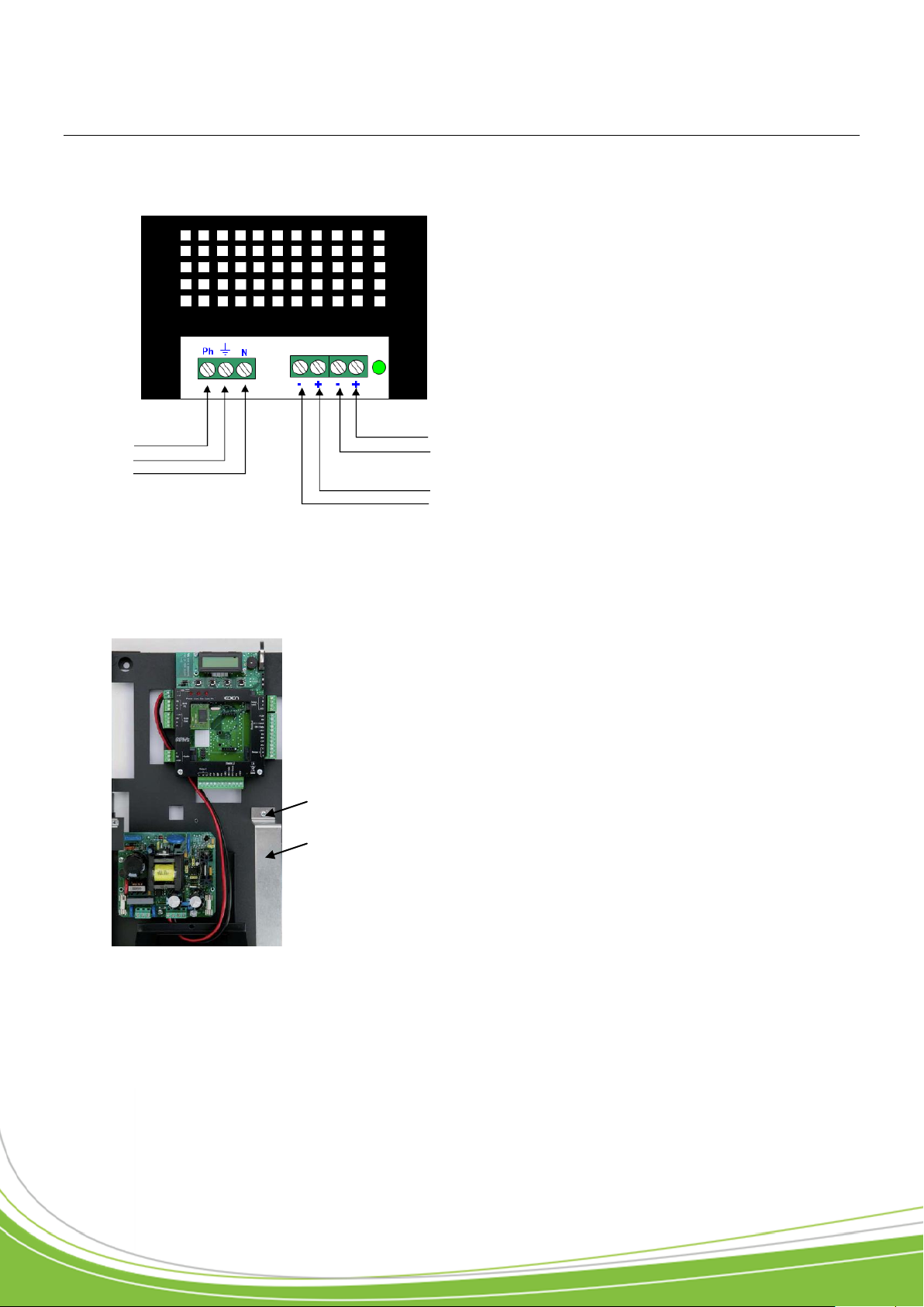
1) Connecting to the power supply .................................................................................... 24
2) Connecting the battery (not supplied) ............................................................................ 24
Check list .............................................................................................................................. 25
Notes ..................................................................................................................................... 26
Page 4

Technical manual C1P2FXBT – V1.7 p 4/28
Acknowledgement
Dear client,
You have just purchased a “C1P2FX” control unit built by EDEN INNOVATIONS.
The entire EDEN INNOVATIONS team would like to thank you for your interest as well as your
confidence in our security solution.
We hope that you will be completely satisfied with the level of security it provides for your company’s premises.
Should you have any comments, please contact us via our web site at
www.eden-innovations.com
The EDEN INNOVATIONS team.
Page 5

Technical manual C1P2FXBT – V1.7 p 5/28
Information and Recommendations
o Pursuant to European directive UTE C00-200, incorporating directives 89/336 EEC and
92/31 EEC, C1P2FX complies with the following standards:
1. NF EN 50081-1 governing electromagnetic radiation, and
2. NF EN 50082-1 governing electromagnetic susceptibility.
o Cabling recommendations: the cables used to connect readers, the network, and other
peripherals must be installed in accordance with the instructions for Level 2 (protected environment) of standard NF EN 61000-4-4.
o This product must be installed by an approved company. Incorrect installation and use
may result in electric shock or fire. Before installation, read the technical information and comply
with the recommendations for installing the product.
o Once the power is turned off, all the internal capacitors will discharge themselves to a
safe level after 60 seconds under normal conditions. However, in the event of a power
failure, the charge may be maintained for much longer and suitable precautions should
be taken before handling the product.
Page 6

Technical manual C1P2FXBT – V1.7 p 6/28
Technical characteristic
1) C1P2FX
Maximum power consumption ........ 300 mA
Power supply voltage ...................... 9 – 14VDC
Weight including the housing .......... 1.05 kg
Housing dimensions ........................ 175 x 154 x 46 mm
........................................................ 6.89 x 6.06 x 1.81 in
Operating temperature .................... -20°C to +50°C
........................................................ -4°F to 122°F
Control relay .................................... 1A / 12V – 1A / 24V
2) C1P2FXBT
Weight including the housing .......... 3 kg
Housing dimensions ........................ 348 x 234 x 96 mm
13.7 x 9.21 x 3.78 in
Operating temperature .................... -20°C to +50°C
........................................................ -4°F to 122°F
Built-in 230 V power supply:
Output voltage ................................. 12V
Maximum output current ................. 5A
Battery connection .......................... 12V, 7Ah (dim. l x d: 151 x 65 mm; 5.94 x 2.56 in)
Control relay .................................... 1A / 12V – 1A / 24V
Page 7

Technical manual C1P2FXBT – V1.7 p 7/28
3 wires
100 m (228 ft)
Ø
0.6 mm (1/30 in) (SYT recommended)
Radio receiver
(JCM, TECHNO EM,…)
Typical arrangement for connection
1) Active aerial
Data sheet:
Characteristic: Sensitive connection
Screen: Mandatory
Simply connect the three wires on the reader to the control unit terminal block as shown.
Note: Do not position the control unit-receiver wires close to other live or high voltage cables
and specifically not close to 230 V cables or higher.
Page 8

Technical manual C1P2FXBT – V1.7 p 8/28
5 wires (3 pairs recommended)
150 m (342 ft)
Ø
0.6 mm (1/30 in) (SYT recommended)
Note: If you use an external
power source to power your
proximity card readers,
ensure that you connect
the various earths to the
one on the control unit.
WIEGAND:
o Proximity card readers
(HID, STID, DESTEIR, INDALA,
etc.)
o Keypads (XPR, etc.)
o Biometric readers (SAGEM, etc.)
o Radio receivers (JCM, TECHNO
EM, etc.)
o DALLAS (via TMCD20 interface)
CLOCK&DATA:
o Magnetic strip readers
o Bar code readers
o Proximity card readers
LED
DATA0 / DATA
DATA1 / CLOCK
0V
+12V/100mA max
2) Identification technology using the WIEGAND / Clock&Data protocol
Data sheet:
Characteristic: Sensitive connection
Screen: Mandatory
Simply connect the three wires on the reader and the power supply to the control unit terminal
block as shown.
Note: The Do not position the control unit-receiver wires close to other live or high voltage
cables, and specifically not close to 230 V cables or higher.
Note: Each reader can accept a different technology (e.g. Reader 1 in Wiegand, Reader 2 in
Clock&Data).
Page 9

Technical manual C1P2FXBT – V1.7 p 9/28
Note: You can connect up to 2 SOLO with
a C1P2FX
A
B
A
B
SYT recommended
1200m (2730 ft) Max
Ø 0.6 mm (1/30 in)
2 pairs recommended
+
12V DC
supply
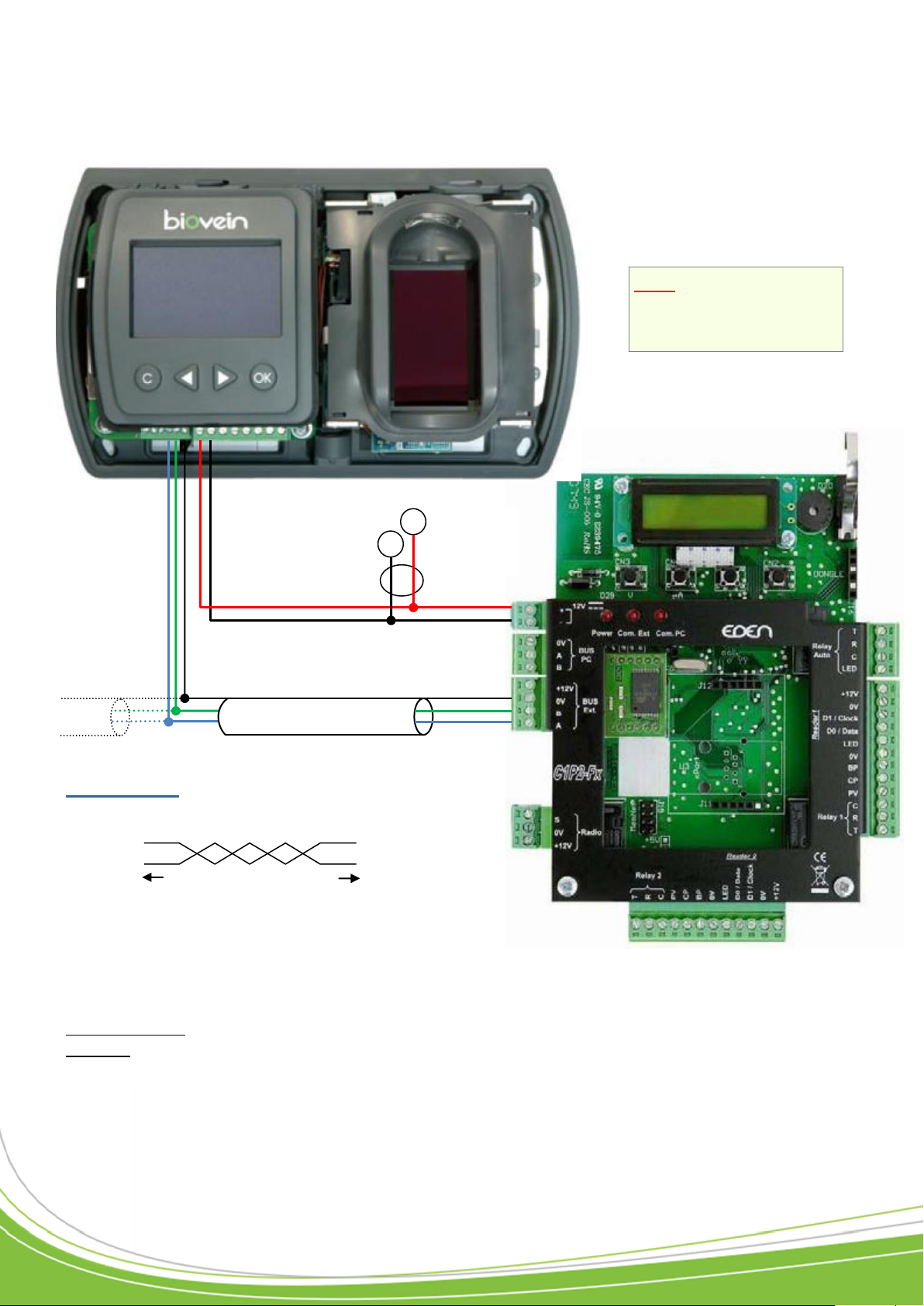
3) SOLO Reader (RS485)
Data sheet:
Be sure to use the same pair for A and B
Be sure to separate the supply from the RS485 bus
Characteristic: Sensitive connection
Screen: Mandatory
To reach 1200 m (2730 ft), you must fit a 120 resistor between points A and B at each end of
the network (see above).
Attention: The total length must not exceed the recommended distance.
Page 10
Technical manual C1P2FXBT – V1.7 p 10/28
RS485
Note: You can connect
up to 2 BIOVEIN with a
C1P2FX
A
B
A
B
SYT recommended
1200m (2730 ft) Max
Ø 0.6 mm (1/30 in)
2 pairs recommended
+
12V DC
supply
4) BIOVEIN Reader (RS485)
Data sheet:
Be sure to use the same pair for A and B
Be sure to separate the supply from the RS485 bus
Characteristic: Sensitive connection
Screen: Mandatory
To reach 1200 m (2730 ft), you must fit a 120 resistor between points A and B at each end of
the network (see above).
Page 11
Technical manual C1P2FXBT – V1.7 p 11/28
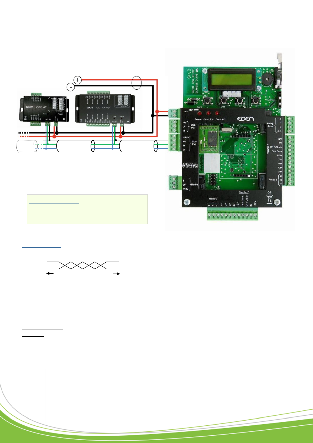
You can connect:
o 10 INFX2 maximum to a C1P2FX
o 10 OUTFX2 maximum to a C1P2FX
ALIMENTATION 12Vcc
RS485
12V DC supply
A
B
A
B
SYT recommended
1200m (2730 ft) Max
Ø 0.6 mm (1/30 in)
2 pairs recommended
5) Extension modules INFX2 and OUTFX2 (RS485)
Data sheet:
Be sure to use the same pair for A and B
Be sure to separate the supply from the RS485 bus
Characteristic: Sensitive connection
Screen: Mandatory
To reach 1200 m (2730 ft), you must fit a 120 resistor between points A and B at each end of
the network (see above).
Attention: The total length must not exceed the recommended distance.
Page 12
Technical manual C1P2FXBT – V1.7 p 12/28
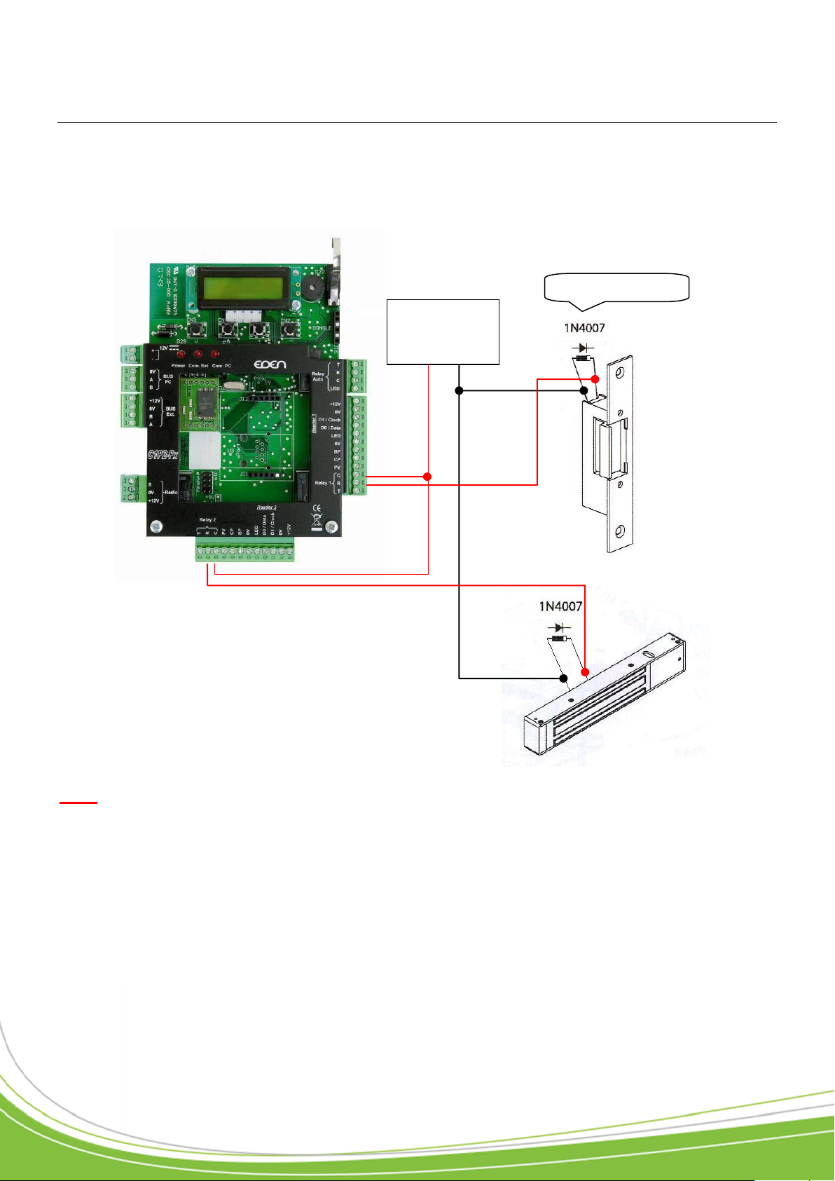
Power supply
+12V 0V
Non-return diode
Typical connection arrangement
1) Power failure door activator and electromagnetic door lock triggered by a pow-
er failure
Note: In order to avoid all the random malfunctions that may interfere with proper use of the
system caused by return currents, it is essential to use and connect the non-return diodes supplied with the control unit in accordance with the wiring diagram above.
Even when using an additional secured power supply for locking, which is separate from the
control unit power supply, it is essential to follow the wiring diagram above.
Page 13
Technical manual C1P2FXBT – V1.7 p 13/28
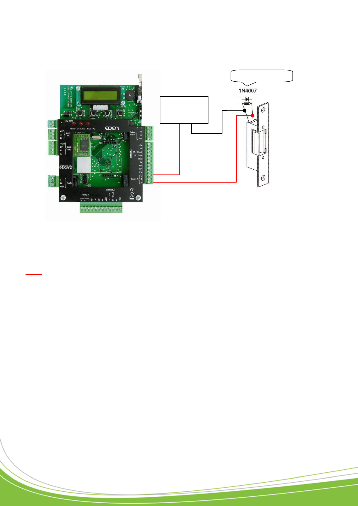
Non-return diode
Power supply
+12V 0V
2) Standard door activator: triggered by a voltage pulse
Note: In order to avoid all the random malfunctions that may interfere with proper use of the
system caused by return currents, it is essential to use and connect the non-return diodes supplied with the control unit in accordance with the wiring diagram above.
Even when using an additional secured power supply for locking, which is separate from the
control unit power supply, it is essential to follow the wiring diagram above.
Page 14
Technical manual C1P2FXBT – V1.7 p 14/28
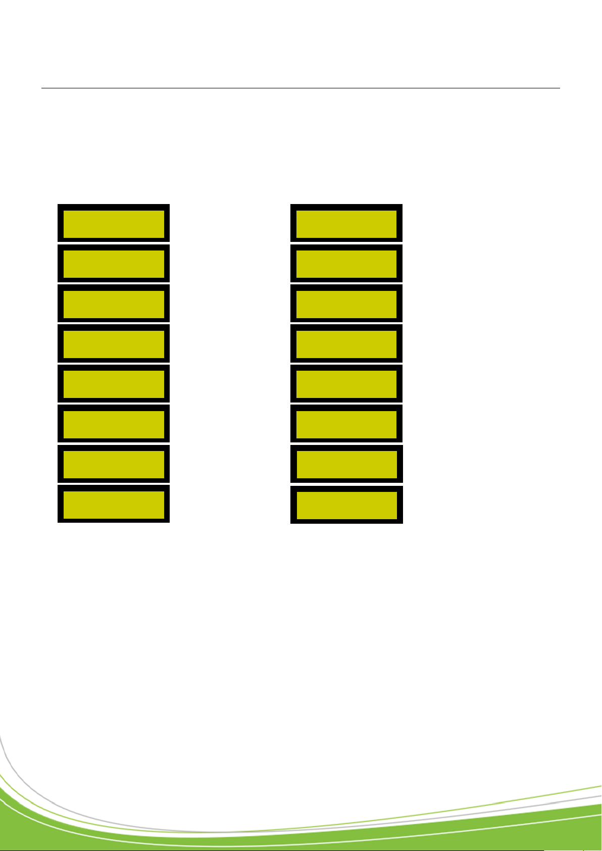
P. 35
P. 39
P. 36
P. 39
P. 36
P. 40
P. 37
P. 40
P. 37
P. 40
P. 37
P. 40
P. 37
P. 40
P. 37
P. 40
USER MANAGEMENT
CONFIGURE
READER 1
VIEW EVENTS
CONFIGURE
READER 2
CONTROL DEVICE
MANAGEMENT
DEVICE TIME
PERIODS
CONTRAST
ADJUSTMENT
USER ACCESS
PERIODS
CLOCK ADJUSTMENT
PUBLIC HOLIDAYS
COMMUNICATION
MODE
CONFIGURE
SITE CODES
CONTROL UNIT
INFO
CONTROL UNIT
CONFIGURATION
DISTRIBUTOR CODES
QUIT MENU?
Using the menus
The control unit has a configuration menu. To access it, press one of the four buttons below the
display.
To navigate the menus, use the “+” and “-” keys. To go back to a menu, use the “V” key. To
quit, press “C” and then “V”.
1) Main menu
Page 15
Technical manual C1P2FXBT – V1.7 p 15/28
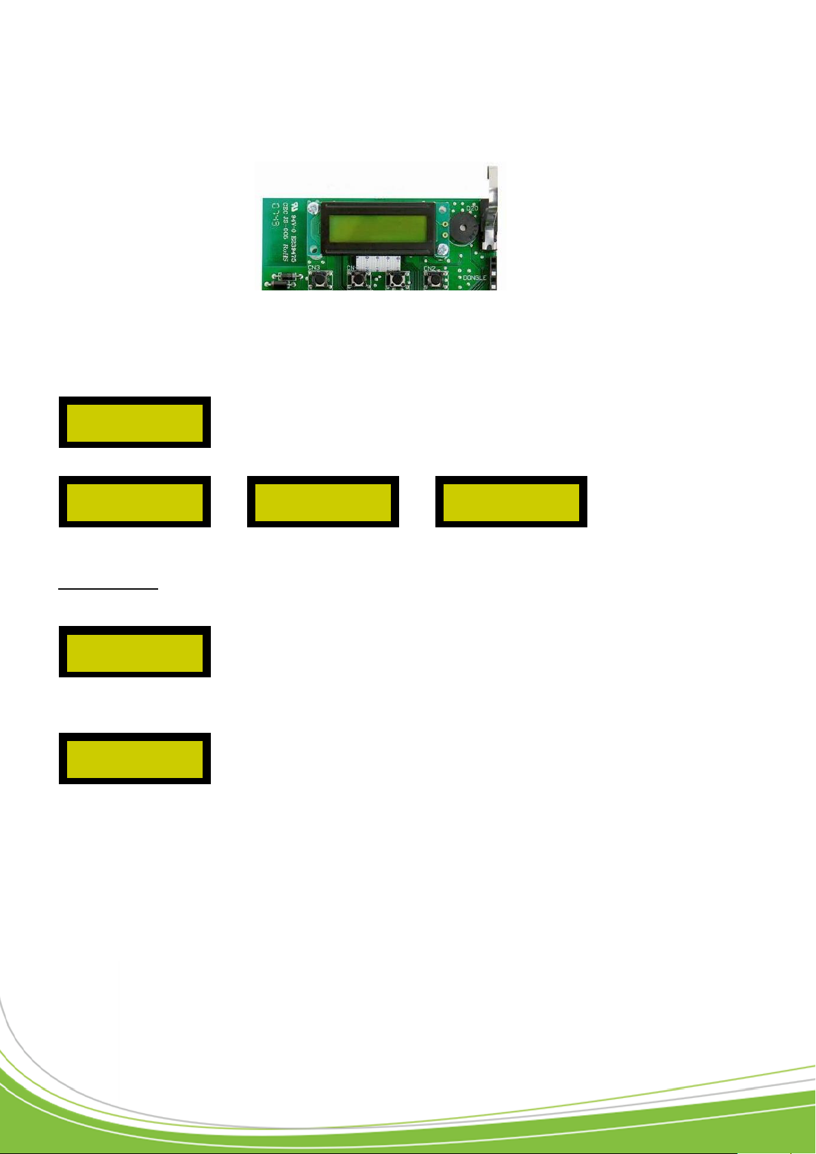
User management
The sub-menu is made up of
Example: To enter the number 1.
BROWSE THE LIST?
DELETE USERS?
CREATE USERS?
USER MANAGEMENT
FIRST NUMBER:
_
FIRST NUMBER:
1_
Confirm Key
(Confirms a menu /
a value entered)
( V )
Scroll Up Key
( + )
Cancel key
(Leaves a menu /
cancels a value
entered)
( A )
Scroll Down Key
( - )
« - »
« - »
2) Using the control unit keys
The control unit has four keys laid out as below:
Once the sub-menu is selected, press the “V” key.
o Create users
Once the menu is confirmed, the control unit asks you to enter the first number.
To do this, scroll through the chosen numbers, using the “+” and “-” keys. To confirm, release
the keys for at least a second. Continue like this until the number is complete.
• You can then confirm it by pressing the “V” key. To erase a figure, press the “A” key.
• Now enter the quantity in the same way and the user authorizations (authorized users as well as
the access time range).
• A summary shows you what data you have entered.
• To confirm, press the “V” key.
Page 16

Technical manual C1P2FXBT – V1.7 p 16/28
Press the “V” key to start enrolment, otherwise
press “C”.
View events
Control device management
ENROLL?
(V) YES (C) NO
VIEW EVENTS
CONTROL DEVICE
MANAGEMENT
o Deleting users: Users are deleted in the same way that they are added.
o Browse the list
This menu allows you to check the list of users registered in the control unit. The “N:” indicates
the user number allocated when it was created while the figure in brackets indicates its position
in the list.
To scroll through the users, use the “+” and “-” keys. To modify the selected user, press the “V”
key.
You can then choose to modify or delete the selected user.
To modify a user, the following menu appears:
If a SOLO or BIOVEIN is connected to the control unit, the following menu appears:
If you want this user to become an “Administrator” (function allowing the enrolment of another
user without even opening the control unit enclosure), press the “V” key, otherwise press “C”.
• Select the badge status (In service, Not allowed, Badge stolen, Suspended).
• Select the authorisations on readers 1 and 2.
• Select the access time range.
• Enter a surname.
• Lastly, enter a first name.
• The control unit allows the storage of the last 10,000 events.
• To navigate the different events, use the (+) and (-) keys.
• To display the badge number, then the name of the user concerned by the event (if such is the
case), confirm using the “C” key.
This menu allows you to activate or deactivate the programmed control devices using an external software package. For this, scroll through the various devices then, using the “V” key, activate or deactivate them.
Page 17

Technical manual C1P2FXBT – V1.7 p 17/28
Contrast adjustment
Clock adjustment
Communication mode
Control unit information
Control unit configuration
CONTRAST
ADJUSTMENT
CLOCK ADJUSTMENT
ADJUSTING MONDAY
11:09 26/07/06
COMMUNICATION
MODE
CONTROL UNIT
INFO
CONTROL UNIT
CONFIGURATION
This menu allows you to adjust the contrast of the display using the “+” and “-” keys.
To exit the menu, press the “V” key.
This menu allows adjustment of the clock.
The display appears as below:
• The fixed cursor indicates the data which you are modifying (in this case, Monday).
• Use the “V” key to move between the data to be configured.
• Use the “+” and “-” keys to modify the data.
This menu allows you to define the communication address (between 1 and 32) using external
software (like SenatorFX or SenatorFX.NET). It also allows you to define the communications
mode (RS485 / MOD-TCPIP) to communicate with EDEN software.
This menu also allows you to force stand-alone mode if your control unit was previously configured by software and you now wish to go back into stand-alone mode.
Here you will find the control unit version and its serial number.
Scroll through the different numbers, using the “+” and “-” keys. The “V” key is used to confirm a
parameter. The “C” key cancels the entered parameter.
Page 18
Technical manual C1P2FXBT – V1.7 p 18/28
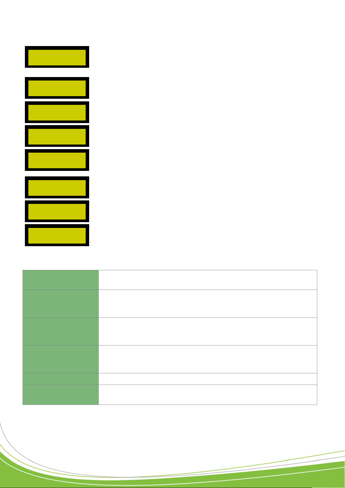
Select the input to use as well as the type of contact, to
watch for unauthorized entry into the enclosure.
Two successive swipes of a badge through the same reader
not allowed. For this, a valid badge must enter through an
entry reader and exit via an exit reader. (The readers must
therefore be configured in the corresponding menu).
Activate / Deactivate the control unit’s radio input.
Select the anti time back delay (time after which a badge
outside the cycle can re-enter/exit again).
Select the transit delay time (maximum time after which a
badge accepted on reader 1 will not be on reader 2 and vice
versa).
Activate / Deactivate the summer / winter time function.
Defines the reader alert level to be recognised by the control
unit.
Defines the communication protocol to be used for reader 1.
Scroll through the different types of reader, using the (+) and
(-) keys.
HID
Management of Wiegand protocols (management of the last bits sent
by the reader). The number of bits is configurable between 16 and 32.
HID Decimal
Management of Wiegand decimal protocols (management of the last
bits sent by the reader). The number of bits is configurable between
16 and 32.
Wiegand custom
Choice between 26-bit Wiegand (with or without management of site
code) and 30-bit Wiegand (with or without management of site and
distributor codes).
ABA / ISO2
Management of ABA protocol (management of the last characters
sent by the reader). The number of characters is configurable between 5 and 8.
SOLO
Management of a SOLO reader with fingerprint recognition.
BIOVEIN
Management of a BIOVEIN reader with recognition of the vein network.
UNAUTHORISED ENTRY
INTO ENCLOSURE
ANTI-PASS-BACK
DEACTIVATED
RADIO INPUT?
ACTIVATED
ANTI-TIME-BACK
DEACTIVATED
TRANSIT DELAY
DEACTIVATED
SUMMER/WINTER TIME?
DEACTIVATED
ALERT LEVEL?
0
STANDARD READER
TYPE 1
This menu comprises:
The following types of reader are available:
Page 19
Technical manual C1P2FXBT – V1.7 p 19/28
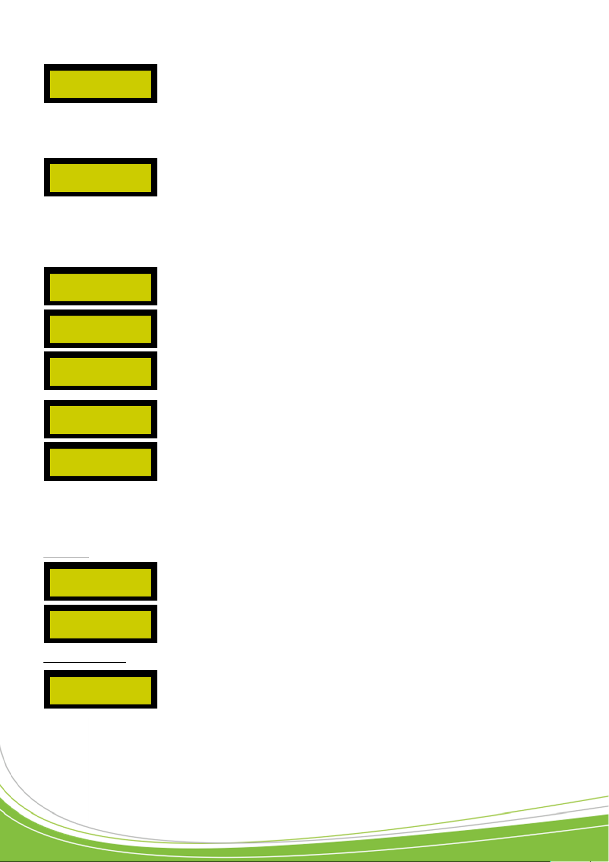
Same as the previous menu.
Configure reader 1
Allows the definition of reader 1 for entry and exit. By
default the reader is neutral.
Allows indication of the output to be used to control an
opening device.
Allows adjustment of the delay during which the relay will
be activated (between 1 and 255 seconds for pulse or
bistable mode).
Allows definition of the input used for the push button.
Same as the push button but for the door contact.
Reader status (Automatic mode / Maintained open / Maintained closed).
Reader free access time range (select here a device time
range).
Configure reader 2
STANDARD TYPE 2
READER
CONFIGURE
READER 1
NEUTRAL APB
BEHAVIOUR
OPENING CONTROL?
NEUTRAL
OPENING TIME?
5 SEC.
PUSH BUTTON
DEACTIVATED
DOOR CONTACT
DEACTIVATED
READER STATUS:
AUTO MODE
FREE ACCESS?
DEACTIVATED
CONFIGURE
READER 2
For the SOLO and BIOVEIN type reader you must enter its identifier (ID on the product serial
number label and its security level (false acceptance rate) and its sensitivity level (detection of
the presence of a finger on the sensor).
Scroll through the different numbers, using the “+” and “-” keys. The “V” key is used to confirm a
parameter. The “C” key cancels the entered parameter.
This menu comprises:
Profile of the different readers. Each reader can function differently depending on the control
unit’s current alert level. For this you have three configurable profiles (one per alert level), as
follows:
Profile 1:
Profile 2 then 3: identical to profile 1
This menu allows the configuration of reader 2 identical to reader 1.
Page 20
Technical manual C1P2FXBT – V1.7 p 20/28
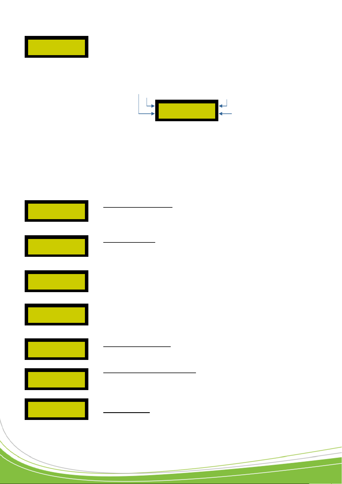
Automated devices time periods (and free
access)
User access periods. You can set up to 64 time ranges
over 10 days (Monday to Sunday plus public holidays) of 10
periods per day for users.
Public holidays. You can configure up to 32 renewable
periods (or not) on the control unit. To add a holiday or list
of specific days, proceed as follows:
Scroll through the days, months and years and then press
“V” to confirm.
When you choose “ACTIVATED”, once the date has
passed, the holiday or period will automatically be renewed
for the following year.
Configure site codes. Here you can configure up to 16 site
codes for the control unit. For this, scroll through the list,
confirm with the “V” key and then enter your site code.
Configure distributor codes. Here you can configure up
to 16 distributor codes for the control unit. For this, scroll
through the list, confirm with the “V” key and then enter
your distributor code.
Quit the menu. Allows you to quit the configuration menu.
DEVICE TIME
PERIODS
USER ACCESS
PERIODS
PUBLIC HOLIDAYS
FROM 01/01/00
TO 01/01/00
RENEWAL?
DEACTIVATED
CONFIGURE
SITE CODES
DISTRIBUTOR CODES
QUIT MENU?
MONDAY (1)
00:00 TO 00:00 OK
Time period
Day of the week
Period number
End
of configuration
You can set up to 32 time ranges over 8 days (Monday to Sunday plus public holidays) of 10
periods per day.
1) Select the range to be configured using the “+” and “-” scroll keys, then press “V” to confirm.
2) Configure your time range.
The display is as follows:
When the cursor flashes, this means that you have to choose the object to configure (Day /
Period number / Time / End of configuration). Scroll through the different objects using the “+”
and “-” keys then press “V” when you have chosen the object to be configured. The cursor then
becomes fixed.
3) Configure the times. Once the object “Time” (00:00 TO 00:00) has been selected, use the “<”
and “>” keys to determine the times, then press “V” to advance the cursor through the different
times.
4) End of configuration.
Position the flashing cursor on “OK” then confirm using the “V” key.
The configuration is done in the same way as for the time ranges for the devices.
Select a period, then “Modify”, confirming with the “V” key.
The following message then appears:
To return a period to zero, select “ERASE” for the desired period and then confirm via the “V” key.
Page 21
Technical manual C1P2FXBT – V1.7 p 21/28
A
B
A
B
SYT recommended
1200m (2730 ft) Max
Ø 0.6 mm (1/30 in)
2 pairs recommended
0V
A
B
0V
A
B
C485FX
For more information,
please refer to the
technical documentation
for this product
A
B
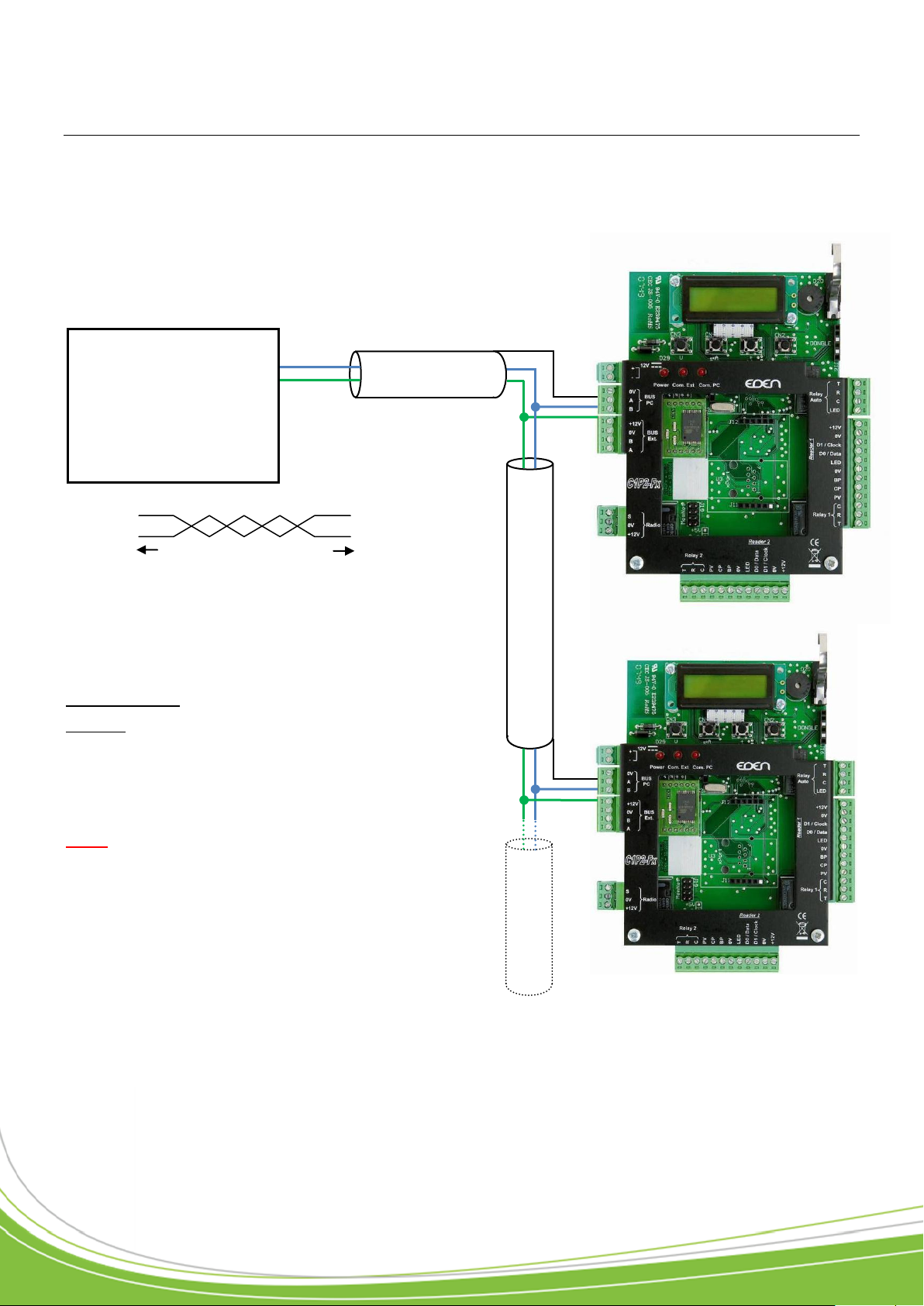
Use in centralized mode
It is essential that you configure an address for your control unit.
To do this, use the control unit menu and go into the “Communication mode” menu to enter the
control unit address (1 to 32).
1) RS485 network
(?) Data sheet:
Be sure to use the same pair for A and B
Be sure to separate the supply from the RS485 bus
Characteristic: Sensitive connection
Screen: Mandatory
To achieve 1200m (2730 ft), you need to install a
120 resistor at each end of the network between
points A and B (see above).
Note: The control units are connected in parallel. It
is possible to go from one control to another or to
several control units: in all cases, the total length
must not exceed the recommended distance.
Page 22
Technical manual C1P2FXBT – V1.7 p 22/28
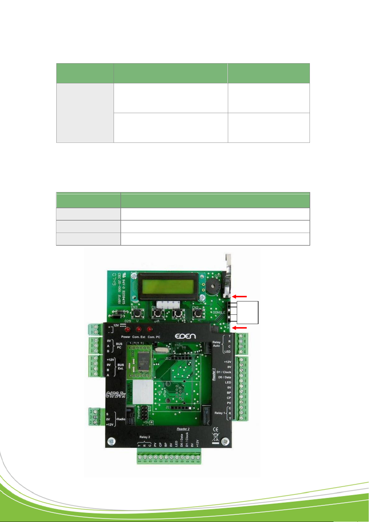
Communication
method
Description
Reference
Ethernet network (TCP/IP):
LAN, WAN,
VPN, ADSL,
WLAN (WIFI)
Wired connection of an RS485
bus on several control units to the
Ethernet network
C485FX + MOD-TCPIP
Wired connection of a single
control unit to the Ethernet network
MOD-TCPIP
DONGLE
Description
DONGLEFXCD16
License to connect up to 16 readers
DONGLEFXCD64
License to connect up to 64 readers
DONGLEFXCD512
License to connect up to 128 readers
Dongle
FX
2) Other communication methods
For more information on these different modules, please refer to the technical documentation
supplied with each module.
3) DONGLE Installation
Page 23
Technical manual C1P2FXBT – V1.7 p 23/28
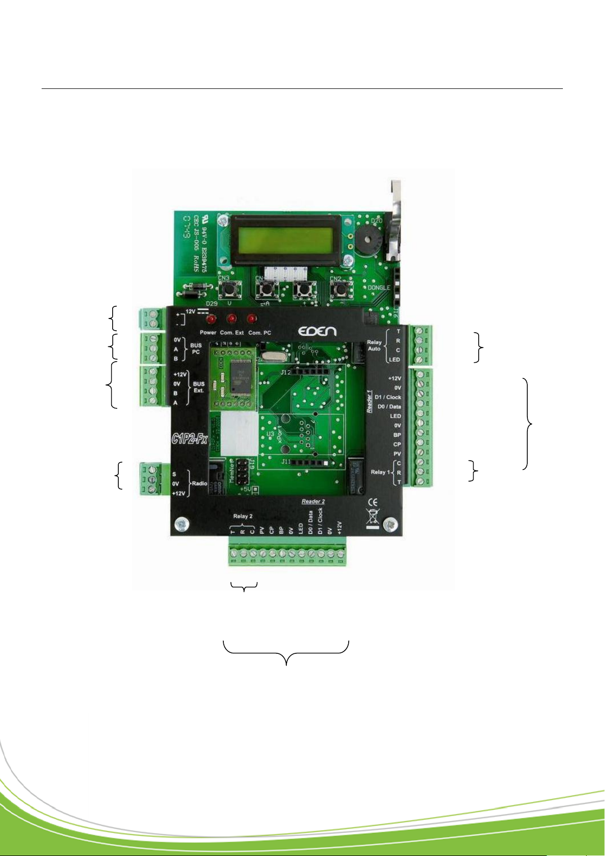
T
R
Com
Auto LED
+12V
GND
Entry 3 / Clock / Data1
Entry 4 / Data / Data 0
LED
GND
Push button
Door contact
Conditional Input
Com
NC
NO
+12V
GND
B
A
+12V
GND
Power supply
BUS 485 PC
BUS 485
Expansion card
S
GND
+12V
Active aerial
Reader 2
GND
A
B
+12V
GND
Entrée3 / Clock / Data1
Entrée 4 / Data / Data0
LED
GND
Bouton-Poussoir
Contact Porte
Conditional Input
Com
NC
NO
Relay
Control
Relay
Reader 1
Connector blocks
Page 24
Technical manual C1P2FXBT – V1.7 p 24/28
230V~
Phase
Earth
Neutral
Battery
+12V
0V
a. Unscrew the 2 mounting screws on the
battery holder.
b. Position your battery (connectors facing
the power supply).
PASS/C1P2FX
+12V
0V
Mounting
screw
Battery
holder
C1P2FX / C1P2FX BT
1) Connecting to the power supply
2) Connecting the battery (not supplied)
Battery to be used: 12V, 7Ah (dim. l x d: 151 x 65 mm; 5.94 x 2.56 in)
c. Connect your battery to the power supply using the cables supplied with the C1P2FX / C1P2FX
BT (ensure that you connect the “+” on the battery to the “+” on the power supply, and the same
for the “-”).
d. Re-attach the holder and check that your battery
Page 25

Technical manual C1P2FXBT – V1.7 p 25/28
Check list
C1P2FX BT
Serial number :
Connector block check :
Silk-screen print :
2 diodes :
Bag :
Screws 4*10 :
Allen key T2,5 :
Power cable red & black :
C1P2FX
Serial number :
Connector block check :
Silk-screen print :
2 diodes :
Bag :
Screws 3*10 :
Allen key T 2 :
Page 26

Technical manual C1P2FXBT – V1.7 p 26/28
Technical Support :
Notes
-------------------------------------------------------------------------------------------------------------------------------
-------------------------------------------------------------------------------------------------------------------------------
-------------------------------------------------------------------------------------------------------------------------------
-------------------------------------------------------------------------------------------------------------------------------
-------------------------------------------------------------------------------------------------------------------------------
-------------------------------------------------------------------------------------------------------------------------------
-------------------------------------------------------------------------------------------------------------------------------
-------------------------------------------------------------------------------------------------------------------------------
-------------------------------------------------------------------------------------------------------------------------------
-------------------------------------------------------------------------------------------------------------------------------
-------------------------------------------------------------------------------------------------------------------------------
-------------------------------------------------------------------------------------------------------------------------------
-------------------------------------------------------------------------------------------------------------------------------
-------------------------------------------------------------------------------------------------------------------------------
-------------------------------------------------------------------------------------------------------------------------------
-------------------------------------------------------------------------------------------------------------------------------
-------------------------------------------------------------------------------------------------------------------------------
-------------------------------------------------------------------------------------------------------------------------------
-------------------------------------------------------------------------------------------------------------------------------
-------------------------------------------------------------------------------------------------------------------------------
-------------------------------------------------------------------------------------------------------------------------------
-------------------------------------------------------------------------------------------------------------------------------
-------------------------------------------------------------------------------------------------------------------------------
-------------------------------------------------------------------------------------------------------------------------------
Page 27

Page 28

Technical manual C1P2FXBT – V1.7 p 28/28
Zone Commerciale et Artisanale
670, route de Berre
13510 EGUILLES
France
www.eden-innovations.com
 Loading...