

Page 1

©2007 Edelbrock Corporation
Brochure #63-0443
Catalog #1400
Rev. 1/07 - RS/mc Page 1 of 5
PLEASE study these instructions carefully before beginning this installation. Most installations can be accomplished with common tools and
procedures. However, you should be familiar with and comfortable working on your vehicle. If you do not feel comfortable performing this installation,
it is recommended to have the installation completed by a qualified mechanic. If you have any questions, please call our Technical Hotline at:
1-800-416-8628, 7:00 am - 5:00 pm, Pacific Standard Time, Monday through Friday or e-mail us at Edelbrock@Edelbrock.com
.
IMPORTANT NOTE: Proper installation is the responsibility of the installer. Improper installation
will void your warranty and may result in poor performance and engine or vehicle damage.
DESCRIPTION: Edelbrock Performer Series carburetor #1400 is 50-state street legal for all 1980 and earlier General Motors V8 engines. All Performer
Series Carburetors have been calibrated, factory flow-tested, and preset. Edelbrock Performer Series carburetors are designed to give you excellent
performance, fuel economy, and maintenance-free operation. To ensure that you enjoy these benefits, please read all instructions prior to installation.
NOTE: Edelbrock Performer Series carburetors are not for computer-controlled applications. That includes some 1981 & later GM
vehicles with Q-Jet carburetor and some 1981 & later Ford vehicles with automatic overdrive (AOD) transmissions.
Vehicles equipped with C.E.C. solenoids will require the use of Edelbrocks Idle Compensator Solenoid. Use part #8059.
The factory C.E.C. solenoid will not fit our throttle lever. However, the Edelbrock Idle Compensator Solenoid will allow you to retain
the C.E.C. function and to pass visual emissions inspection in California. See “C.E.C. Function” in the “Adjustments and
Troubleshooting” section for installation and adjustment of the Idle Compensator.
KIT CONTENTS:
❑ 2 5/32” Vacuum caps
❑ 1 5/32” Vacuum “T”
❑ 1 1/4" NPT pipe plug
❑ 1 Throttle cable ball end stud
❑ 1 10-32 Hex nut
❑ 1 Installation instruction sheet
❑ 1 Warranty card
❑ 1 Square-bore, heat-insulating gasket
❑ 1 Air horn gasket
❑ 1 Air cleaner stud
❑ Carburetor Adapter and Fuel Line Kit #2697 (Used to mount
Edelbrock carburetors to stock Quadrajet manifolds. Includes
4-hole carb adapter #2696, fuel filter and fuel line kit #8135 for
3/8" and 5/16" OEM steel fuel lines. Both also available separately)
❑ 90-degree banjo fuel inlet fitting kit #8089 (For use with low profile
air cleaner bases), #6 AN fuel inlet fitting #8087, or Inverted Flare
fuel line fitting #8090 (3/8")
❑ In-line fuel filter #8873
❑ Fuel pressure regulator #8190 (If stock fuel pressure is greater than
6.5 psi)
❑ Chevrolet throttle cable stud #8009 (’77 & later)
❑ Transmission kick-down stud #8018 (TH350 type)
❑ GM cruise control adapter #1484
❑ Throttle cable, transmission, and cruise control bracket #8031 or
8036 (‘79 and earlier) for small-block or big-block Chevy (Some
applications may require modification to stock bracket)
❑ EGR adapter #1476 (For Chevy small-block V8’s. Required for all
EGR applications to provide clearance for Performer Series
carburetors)
❑ Universal throttle return spring kit #8005 (If original return spring
cannot be used)
❑ 3/4" Air Cleaner spacer #8092 (For low profile air cleaner bases to
clear electric choke)
❑ Electrical connectors (For electric choke connection)
EDELBROCK PERFORMER SERIES EMISSIONS LEGAL CARBURETOR
600cfm, Electric Choke, EGR, Square-Bore Carburetor
Catalog #1400
INSTALLATION INSTRUCTIONS
❑ Replace fuel filter. Dirt found in carburetor voids warranty.
❑ Check and replace the air filter, if necessary.
❑ Check PCV valve and replace, if clogged.
❑ Check all hoses for leaks or cracks and replace, if necessary.
❑ Check fuel pump for proper operation and replace, if necessary.
❑ Check the intake manifold and cylinder head gaskets for leaks and
replace, if necessary.
❑ Check the ignition system: clean and gap or replace spark plugs,
plug wires, and adjust ignition timing.
CHECK THE FOLLOWING BEFORE BEGINNING INSTALLATION
WARNING: WHEN WORKING AROUND GASOLINE, ALWAYS WORK IN A WELL VENTILATED AREA, AND KEEP ALL OPEN FLAMES, SPARKS AND
OTHER SOURCES OF IGNITION AWAY FROM THE WORK AREA. FAILURE TO DO SO CAN RESULT IN A FIRE
OR EXPLOSION.
ACCESSORIES (REVIEW THE FOLLOWING AND USE PARTS AS NECESSARY FOR YOUR APPLICATION)
❑ 1 3/16” Internal star washer
❑ 1 Red choke positive wire
❑ 1 Black choke ground wire
❑ 1 E.O. Decal
®
Page 2
©2007 Edelbrock Corporation
Brochure #63-0443
Catalog #1400
Rev. 1/07 - RS/mc Page 2 of 5
INSTALLATION PROCEDURE
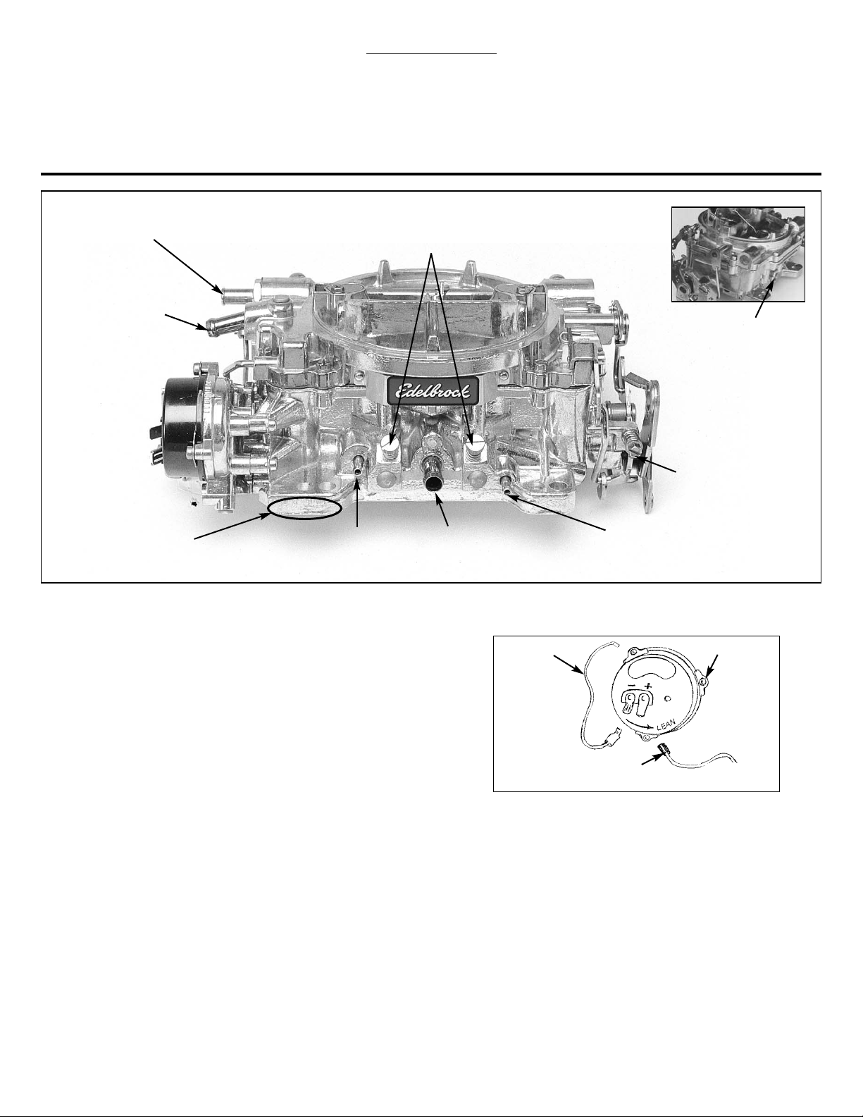
Figure 1 - Fittings and Vacuum Port Locations
CANISTER VAPOR VENT
(#1400 ONLY)
IDLE MIXTURE SCREWS
Left side screw for left side of carb
Right side screw for right side of carb
FUEL INLET for 3/8” hose (Except marine
models #1409 & #1410 which use a 3/8”
inverted flare fitting)
POWER BRAKE PORT
(Except Marine Models)
Rear lower side, 1/4” NPT
MUST BE PLUGGED WITH
1/4” PIPE PLUG (SUPPLIED)
IF NOT USED
IDLE SPEED
SCREW
PCV PORT (For 3/8” hose)
NOT FOR FUEL!
3/16” MANIFOLD VACUUM PORT
(EGR vacuum supply port)
3/16” TIMED VACUUM PORT
(Distributor vacuum advance port for
emissions controlled engines)
PART NUMBER is stamped on
pad at front of carburetor
CARBURETOR PREPARATION
1.
Install proper throttle and transmission linkage for your particular
application. Make sure all linkage is properly secured to carburetor and
works freely.
2.
Check and prepare carburetor for proper vacuum fitting installation
(EGR,
power brakes, PCV, distributor, transmission, etc.) using supplied
vacuum caps, “T”, and hose when applicable. Before removing old
carburetor, determine if distributor vacuum advance port is “timed” (no
vacuum present at idle) or “manifold vacuum” (vacuum present at idle),
and use the matching vacuum port on your Edelbrock carburetor
(See
Figure 1)
. If vacuum port at rear of carb is not used, plug with a 1/4"
pipe plug.
3. For electric choke hook-up
(See Figure 2)
, remove one choke
housing retaining screw and install eyelet end of choke ground wire
(black) to choke housing and reinstall screw. Connect clip end of
choke ground wire to negative (-) spade terminal on choke housing.
Connect red wire spade terminal to positive (+) terminal on choke
housing. Connect other end of red wire to an ignition key activated
12-volt source. DO NOT ATTACH TO COIL OR ALTERNATOR. Ensure
this source maintains 12 volts with engine running.
INSTALLATION OF CARBURETOR
1. Disconnect all linkages and lines from old carburetor, noting their
purpose for reassembly on new carburetor.
CAUTION: When disconnecting fuel line, avoid any exposure to
sparks or open flame. Note position of all throttle and transmission
linkages and/or cables for reassembly. Remove old carburetor and
flange gasket. Do not allow gasket or other material to fall into
manifold.
2. Place new carburetor gasket and adapters (when applicable) on the
manifold. Install carburetor and cross tighten nuts. Be sure not to
overtighten nuts.
Fig. 2
Black Wire (–);
To Ground
(Carb Body)
Red Wire (+); To Key-On 12V
Source
(Not Coil or Alternator!)
Retaining Screws (3)
RECOMMENDED TOOLS
❑ Sockets/wrenches/tubing wrenches
❑ Pliers
❑ Screwdrivers
❑ Hacksaw and/or tubing cutter
❑ #20 Torx Driver (for electric choke models)
❑ Wire crimpers (for electric choke models)
❑ Test Meter or Test Light (for electric choke models)
Page 3

©2007 Edelbrock Corporation
Brochure #63-0443
Catalog #1400
Rev. 1/07 - RS/mc Page 3 of 5
IDLE MIXTURE
The Edelbrock Performer Series carburetor has conventional Idle Mixture
Screws (IMS) that provide a leaner A/F when turned clockwise and richer
A/F when turned counter clockwise. The idle air flow is controlled by a
conventional screw that opens the Primary Throttles. The following
procedure should be used to set the idle mixture and speeds:
1. Fully warm engine and ensure choke is fully open.
2. Air cleaner in place.
3. Set desired speed with the air screw.
4. Adjust the IMS on ONE side to get the maximum possible RPM. Do
not go rich beyond the maximum speed point.
5. If the above changed the idle speed more than 40 RPM, then
re-adjust the speed.
6. Adjust the side OPPOSITE of that in Step 4 to get maximum RPM.
7. Reset the speed.
8. Carefully trim each IMS to again get the maximum idle RPM.
9. Go leaner just enough to get a 20 RPM drop in speed.
10. Reset the speed to the desired RPM.
11. This is a Lean-Best Idle Set. Setting richer than this will not
improve idle quality or performance, but could tend to foul spark
plugs.
WINTER FUEL IDLE SETS
During the winter months (in most parts of the country) the local fuel will
be a “winter” blend that is very volatile, as an assist to cold-engine
starting and driveability during warm-up. However, the high volatility has
the disadvantage of allowing excessive vaporization of the fuel if the
vehicle is operated in a heated area such as a garage. This can result in
problems in the idle-set procedures since the carburetor’s internal vents
will allow this excess vapor to be drawn into the throats and enrichen the
mixture. The idle will be erratic and not seem to be able to hold a set.
To resolve this type of problem, it is advisable to perform the final
settings outdoors after the vehicle has been stabilized with a drive of
several miles.
CALIBRATING THE ACCELERATOR PUMP
If you encounter any hesitations or stumbles that do not seem to be
related to the basic metering or have not responded to changes in the
basic metering, move the pump drive link to one of the holes closer to
the carburetor body. This will increase the stroke length of the plunger
and result in more pump delivery.
FLOAT ADJUSTMENT
To properly adjust the floats in the EPS carburetor, two procedures must
be followed. First, the metering rod/power piston assemblies should be
removed from the top of the carb airhorn. Next, remove the accelerator
pump connecting rod and the choke connec-ting rod. After removing all
the airhorn retaining screws, turn the airhorn upside down with the
gasket in place
(See Figure 3)
. Use a scale, or a 7/16" drill bit (as
shown) to mea-sure the float level. There should be 7/16" between the
air-horn gasket and the top of the outer end of the float. To adjust the
float level, bend the float lever until the recommended level is attained.
DO NOT press the needle into the seat when adjusting the float lever.
Next, you should check the float drop
(See Figure 4).
Hold the airhorn
upright and let the floats hang down. There should be 1-1/4" ± 1/4"
between the airhorn gasket and the top of the outer end of the float. To
adjust the float drop, bend the tab on the back until the recommended
float drop is attained.
3. Connect all throttle and transmission linkages and throttle return
springs.
CAUTION: At this point, make sure all throttle and transmission
linkages operate smoothly from idle to wide open throttle (WOT)
and check return springs for proper pressure.
4. Connect all vacuum hoses to their proper location on carburetor
(See Figure 1)
. Replace hoses that appear brittle or cracked.
5. Connect fuel line to carburetor
(See Figure 1)
. Avoid contact with
any sharp edges or areas of extreme heat. For best results, use
Edelbrock in-line fuel filter #8873 and fuel line kit #8135.
6. Install new air horn gasket and air cleaner stud (supplied). Install
air cleaner making sure it does not contact linkage or fuel line and
has proper hood clearance. Extremely low profile air cleaners will
not fit without #8092 (due to choke interference).
7. Trim air cleaner stud to proper length.
8. Re-check all linkage for smooth throttle operation.
9. Start the engine and check for any possible fuel or vacuum leaks.
CAUTION: Be alert to carburetor flooding. Flooding can be caused
by dirt, small particles of hose cuttings, floats and inlet needles
which have settled during shipping. When the fuel pump is turned
on or when the engine is first started, watch closely for signs of
flooding. If flooding occurs turn engine off immediately and lightly
tap on the side of the carburetor that is flooding, in the rear needle
and seat area with a rawhide mallet or wooden handle of a
hammer. Start engine and see if flooding continues. If flooding
continues, stop the engine. Clean up any raw gasoline and refer to
the “Adjustments and Troubleshooting” section of the
Instruction Sheet.
WARNING: NEVER POUR FUEL DIRECTLY DOWN THE
CARBURETOR WHEN ATTEMPTING TO START THE ENGINE! THIS
MAY CAUSE A BACKFIRE AND POSSIBLE ENGINE
COMPARTMENT FIRE, RESULTING IN ENGINE OR VEHICLE
DAMAGE, PERSONAL INJURY AND/OR DEATH.
10. With engine at normal operating temperature and choke fully open,
set idle speed and mixture screws. This procedure is outlined in the
Instruction Sheet.
ADJUSTMENTS AND TROUBLESHOOTING
Float Level
(7/16")
Bend Here
Fig. 3
Page 4

CHOKE ADJUSTMENT
To adjust the choke piston linkage
(See Figure 5)
, open the choke valve and
insert a .026" wire, with a 90-degree bend 1/8" from the end, between the
top of the slot in the choke piston cylinder and the bottom of the slot in the
piston. Hold the wire in position and close the choke valve by pressing on
piston lever “A” until resistance is felt. The dimension “C” should be .100"
between the top edge of the choke valve and the air horn. To adjust, bend
rod “B”.
©2007 Edelbrock Corporation
Brochure #63-0443
Catalog #1400
Rev. 1/07 - RS/mc Page 4 of 5
To adjust the fast idle linkage
(See Figure 6),
place the fast idle screw A
between the two notches on the cam. Close the choke valve as far as
possible without forcing it. The dimension C should be 3/64" between the
choke valve and the air horn. To adjust, bend rod B.
Fast idle may be
adjusted to manu-facturer’s specifications (usually 1500 rpm) during
normal choke cold operation. The fast idle screw A can be adjusted with
engine off and throttle held open to allow screw head access. Re-check
fast idle speed after each adjustment.
C (3/64")
B
A
Fig. 6
Slot (Piston)
.026" Wire
C (.100")
A
B
Fig. 5
Tab
Float Drop (1-1/4 ± 1/4")
Fig. 4
The length of time during which the choke will stay closed is determined
by the position of the choke cap. As the choke cap is turned clockwise,
the choke will stay closed longer. To properly set the choke, turn the
choke cap to the leanest notch on the choke housing, tighten the choke
housing retaining screws, and run the engine until normal operating
temperature is reached. With the engine running, slowly turn the choke
cap clockwise until the choke valve begins to close. Now turn the choke
housing one notch counterclockwise (LEAN) and tighten the choke
housing retaining screws. Periodic re-adjustment of the choke will be
required as the temperature changes throughout the year. After each
adjustment, verify that the choke valve opens fully after the engine is
warm.
CAUTION!!!
Do not overtighten the small Power Piston Cover screws when
servicing metering rods. They should only be tightened to 12
to 17 inch/pounds. Excessive torque will weaken or snap off
the screw heads. If this happens, they may fall into the
carburetor causing serious engine damage. If an inch/pound
torque wrench is not available, snug the screw until it just
touches the plate, then tighten 1/16th turn more.
C.E.C. FUNCTION
Vehicles equipped with C.E.C. solenoids will require the use of
Edelbrock’s Idle Compensator Solenoid. Use part #8059. The
factory C.E.C. solenoid will not fit our throttle lever. However,
the Edelbrock Idle Compensator Solenoid will allow you to retain
the C.E.C. function and to pass visual emissions inspection in
California.
Remove front driver’s side carb stud and replace with longer stud
supplied in this kit. Place bracket over the stud and install nut and
washer on stud. Position solenoid in bracket and install large washer
(locking tabs face the solenoid) and locknut. Tighten firmly, but be
careful not to over-tighten due to the large size (1-1/4") of the wrench
used. Bend locking tabs on special washer over flats of the nut to
prevent loosening. Attach the wire from the solenoid to the existing
C.E.C. wiring connector.
If the factory connector does not fit, you will need to splice into the wire
from the connector. Use a 1/4" female receptacle and at least 18-20
gauge wire. Some receptacles will require that the locking tab on the
solenoid be flattened before the receptacle will fit.
ADJUSTMENT
With the Idle Compensator Solenoid disconnected, adjust the Idle
Speed Screw until you reach the desired idle RPM.
With the Idle Compensator Solenoid connected and the ignition in
the “On” position, adjust the solenoid until it just contacts the
throttle lever. Next, start the engine and turn the Idle Speed Screw
counter-clockwise to make sure the idle speed is maintained by the
solenoid. If necessary,adjust idle speed by turning solenoid plunger
in or out with a 1/2" wrench. Shut off the engine.
Turn the Idle Speed Screw counter-clockwise until the throttle lever
is completely closed and the Idle Speed Screw is not touching the
throttle lever. Turn the Idle Speed Scruew clockwise until it just
makes contact with the throttle lever. Continue turing 1/4 turn
more. This will make sure the throttle blades will not bind in the
bore when the solenoid is turned off.
Page 5

©2007 Edelbrock Corporation
Brochure #63-0443
Catalog #1400
Rev. 1/07 - RS/mc Page 5 of 5
X X XXXX X X X
XXXXXXXX
XXXXX X X
XX XXX
XX X X X
XXX X
XX
XX
XX X
XXXX
XX XX
XX XX
XXX
XX XX
XX
X
X
Check for air leaks. Make sure carburetor and manifold gaskets
seal properly. All outlets must be plugged or connected.
Check ignition system. Replace parts as necessary. Adjust timing to
proper specifications.
Check choke adjustment.
Change carburetor fuel filter and/or in-line fuel filter.
Check float level and drop.
Check idle mixture screw adjustment.
Increase accelerator pump stroke. Pump squirter size change may
be needed.
Off-road vehicle may need spring-loaded needle and seat kit
Check for dirt or metal in needles and seats. Needles and seats
may need replacement.
Check for dirt blocking the low speed circuit. Clean unit and apply
air pressure. Install in-line fuel filter #8873.
Check floats for leakage. Replace, if necessary.
Check air horn gasket. Replace, if deterioration or breakage is
present.
Fuel is boiling due to excessive under hood temperature.
Fuel pressure too high. Fuel regulator may be needed.
Fuel pressure too low. Check fuel system.
Check secondary latching device and rod for proper movement.
Lower float level from 11/32” to 7/16”.
Carburetor doesn’t
adjust properly
Carburetor floods
Fuel leaks at shaft
Internal fuel leak
Misses or surges
Stumbles or loads up
Engine won’t idle
Rough idle
Backfires
Bogs
Hard starting
Lack of power
Pinging at moderate
cruise just off idle
Engine stalls on hard
braking
Low fuel economy
Possible Solutions
Symptoms
TROUBLESHOOTING CHART
(Refer to the chart below for reference)
Page 6

©2007 Edelbrock Corporation
Brochure #63-0443
Catalog #1400
Rev. 1/07 - RS/mc
Edelbrock Corporation • 2700 California St. • Torrance, CA 90503
Tech-Line: 800-416-8628 • E-Mail: Edelbrock@Edelbrock.com
®
 Loading...