


E D E L B R O C K
PERFORMER SERIES® CARBURETOR
Owner’s Manual
For these Performer Series Carburetors: 1403, 1404, 1405, 1406, 1407, 1409, 1410, 1411, 1412 and 1413

INTRODUCTION
Your Edelbrock Performer Series carburetor was calibrated using Edelbrock Performer, Performer RPM, and Torker II Power Packages. The carburetor metering was developed on Edelbrock engine dynamometers, chassis rolls, and a variety of development vehicles. Although in most applications you will not need to recalibrate your carburetor, you may wish to change the factory calibration to best meet any unique needs of your engine. The following manual consists of 2 sections; Theory of Operation and Tuning Procedure. Upon review of Section 1, Theory of Operation, you will be prepared to develop your own individualized calibration. Section 2, Tuning Procedures will take you through a step-by-step procedure that will enable you to achieve a desirable calibration. For added ease of tuning, a Calibration Reference Chart for your model of carburetor has been included.
|
TABLE OF CONTENTS |
|
SECTION 1: |
THEORY OF OPERATION ....................................................................... |
2 |
|
BASIC ENGINE REQUIREMENTS ............................................................ |
2 |
|
METERING SYSTEMS............................................................................ |
3 |
|
1. Idle System .............................................................................. |
3 |
|
2. Primary Main System ................................................................ |
4 |
|
3. Secondary Main System............................................................ |
6 |
|
TRANSIENT CONTROL SYSTEMS .......................................................... |
6 |
|
1. Secondary Auxiliary System ..................................................... |
6 |
|
2. Pump System ........................................................................... |
7 |
|
EXTERNAL DEVICES.............................................................................. |
8 |
|
Fuel Pumps and Pressure.............................................................. |
8 |
|
Air Cleaners .................................................................................. |
9 |
SECTION 2: |
TUNING PROCEDURE ............................................................................ |
9 |
|
REVISING THE CALIBRATION................................................................. |
9 |
|
Parts and Equipment .................................................................. |
10 |
|
Changing Components ................................................................ |
11 |
|
IDLE MIXTURE .................................................................................... |
11 |
|
Winter Fuel Idle Sets .................................................................. |
11 |
|
Long Duration Camshaft.............................................................. |
12 |
|
CALIBRATING THE |
|
|
WIDE-OPEN THROTTLE (WOT) ............................................................ |
12 |
|
CALIBRATING THE PART THROTTLE.................................................... |
13 |
|
Cruise Mode................................................................................ |
13 |
|
Power Mode ............................................................................... |
14 |
|
CALIBRATING THE POWER MODE STAGING......................................... |
14 |
|
CALIBRATING THE PUMP .................................................................... |
14 |
|
FLOAT ADJUSTMENT ......................................................................... |
14 |
|
CHOKE ADJUSTMENT......................................................................... |
15 |
|
SPECIAL CALIBRATIONS .................................................................... |
16 |
|
CARBURETOR SPECIFICATIONS .................................................... |
16, 17 |
|
CALIBRATION REFERENCE CHARTS............................................... |
18-31 |
|
APPENDIX ..................................................................................... |
32-38 |
|
Exploded View....................................................................... |
32, 33 |
|
Troubleshooting Information. ................................................. |
34-36 |
|
WARRANTY ....................................................................................... |
37 |
|
EDELBROCK CARBURETOR DATA LOG ............................................... |
38 |
1 Edelbrock Performer Series Carburetor Owner’s Manual 3/00

SECTION 1: THEORY OF OPERATION
BASIC ENGINE REQUIREMENTS
The spark-ignition 4-cycle engine burns a mixture of AIR and FUEL. The air is controlled by the driver’s operation of the throttle. The fuel is mixed with the incoming air by the carburetor. The Ratio of AIR to FUEL is the AIR/FUEL Ratio (A/F). This is a ratio by WEIGHT; if 12 pounds of Air are combined with 1 pound of Fuel the A/F is 12:1, or more commonly, A/F = 12.
Despite the enormous variety in engine designs, virtually all (spark-ignition 4-Cycle) engines have very similar A/F Ratio requirements. For fully warmed-up engines, the range of A/F is:
A/F RATIO |
CHARACTERISTICS |
5 |
RICH BURN LIMIT: Combustion is weak/erratic. |
6-9 |
EXTREMELY RICH: Black smoke and low power. |
10-11 |
VERY RICH: Some supercharged engines run in this range at full power as a |
|
means of controlling detonation. |
12-13 |
RICH: Best power A/F: Un-supercharged WOT. |
14-15 |
CHEMICALLY IDEAL: At 14.6 the A/F is at the theoretical ideal ratio with no |
|
excess fuel or oxygen after combustion. Good A/F for part |
|
throttle cruise and light to moderate acceleration. |
16-17 |
LEAN: Best economy A/F ratio. Borderline for part throttle |
|
drivability (worse than borderline if EGR is used). |
18-19 |
VERY LEAN: Usual lean limit (Driveability). |
20-25 |
LEAN BURN LIMIT: Varies with engine and system. |
Even though engines will run anywhere between 5 and 25 A/F, the usual target values for an unsupercharged engine are a fairly narrow range (Figure 1). A/F is about 12.5 for the WOT and 14.0- 15.5 at part-throttle cruise. An intermediate value of about 13.5-14.0 is usually used for mid-range power (non-WOT acceleration).
2 Edelbrock Performer Series Carburetor Owner’s Manual 8/94
Lean 17.0 |
|
|
|
|
|
|
|
|
|
|
|
16.0 |
|
|
Part-throttle cruise |
|
|
|
|
||
|
|
|
|
|
|
|
|
|||
A |
15.0 |
|
|
|
|
|
|
|
|
|
/ |
|
|
|
|
|
|
|
|
|
|
|
|
|
|
|
|
|
|
|
|
|
F |
|
|
|
|
|
|
|
|
|
|
|
14.0 |
|
|
|
|
|
|
|
|
|
R |
|
|
|
Part-throttle acceleration |
|
|
|
|||
A |
13.0 |
X |
|
|
|
|
|
|
|
|
T |
|
|
|
|
|
|
|
|
||
|
Idle |
|
|
|
|
|
|
|
|
|
I |
|
|
|
|
|
|
|
|
|
|
|
|
|
Wide open throttle |
|
|
|
|
|||
O |
12.0 |
|
|
|
|
|
|
|||
|
|
|
|
|
|
|
|
|
||
|
11.0 |
|
|
|
|
|
|
|
|
|
Rich |
10.0 |
|
|
|
|
|
|
|
|
|
|
0 |
1000 |
2000 |
3000 |
4000 |
5000 |
6000 |
7000 |
8000 |
9000 |
|
|
|
|
|
Engine RPM |
|
|
|
|
|
Typical Engine A/F Ratios
Figure 1
METERING SYSTEMS
The Edelbrock carburetor has three (3) basic systems that meter fuel to the engine: The Idle System, Primary Main System, and Secondary Main System. By understanding the operation of each you will be better prepared to calibrate your carburetor.
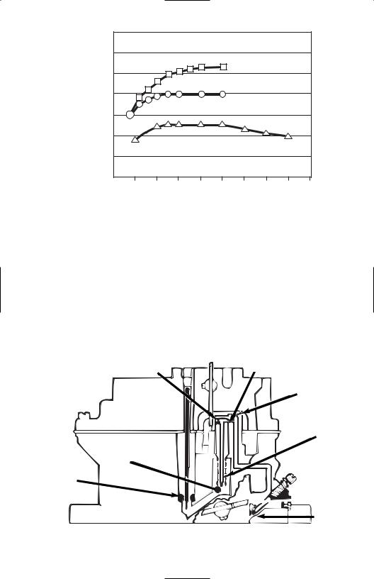
Idle System: The Idle System delivers 100% of the idle fuel. It also meters fuel at off-idle throttle positions; a large percentage at just off of idle decreasing to a minor influence as the throttle is opened wider. The idle setting is critical both to a smooth idle at proper rpm and to a smooth transition to part-throttle operation.
(4) 1st Idle Air Bleed |
(5) Idle Channel Restrictor |
|
(6) 2nd Idle Air-Bleed
(3) Idle Jet
(2) Primary Well
(1) Main Jet and
Metering Rod

 (7) Transfer Slot
(8) Idle
Screw
Port
Idle System
Figure 2
3 Edelbrock Performer Series Carburetor Owner’s Manual 8/94

Fuel is drawn through the Idle System (Figure 2) by the intake manifold vacuum that is communicated at the Idle Screw Port (8) and Transfer Slot (7). Fuel in the bowl passes through the Primary Main Jet and Metering Rod Restriction (1) and into the Primary Well (2). The fuel for the Idle System is drawn through the restriction at the end of the Idle Jet (3) - a brass tube - and flows up the tube to the location of the 1st Idle Air Bleed (4) - a brass restrictor - where air is mixed with the liquid fuel. The emulsified air and fuel is then drawn through the Idle Channel Restrictor (5) - a drilled passage that serves to increase the velocity of the air and fuel to promote better mixing. As the emulsified fuel is discharged from the Idle Channel Restrictor, additional air is added at the 2nd Idle Air Bleed (6) - a drilled hole - and the highly aerated mixture then moves through the passages in the main-body to the location of the Transfer Slot (7) and Idle Screw Port (8). The Transfer Slot (7) is a large air bleed when the throttle is closed, but as the throttle is opened the slot is exposed to manifold vacuum and becomes a discharge port for Idle System fuel. The Idle Screw Port is a variable discharge restriction that is adjusted by the engine tuner to achieve the desired A/F Ratio at engine idle.
Primary Main System: The Primary Main system delivers an increasing percentage of the fuel as throttle position increases (phasing over the Idle System) and varies fuel delivery in response to air flow and manifold vacuum.
Fuel is drawn through the Main System (Figure 3) by the pressure-drop that occurs when the incoming air flow must increase in velocity in order to pass the reduced throat areas at the Main Venturi (1) and the Boost Venturi (2). This pressure-drop (or suction) is communicated to the system by the Nozzle (3)-a brass tube that opens into the inside of the Booster Venturi (2).
The fuel must pass through the restriction at the Main Jet (4) and Metering Rod (5). The Rod extends through the Jet, reducing the amount of area available for fuel flow. If the diameter of the Rod is large, then fuel flow through the Jet is more restricted than if the Rod were small.
After the Rod and Jet, the fuel enters the Primary Well and is drawn up the inside of the Primary Well Tube (6). Sometimes this tube is called an Emulsion Tube. Here, the fuel is mixed with air that enters the inside of the Tube through a series of small holes. The air is supplied by the Main Well Bleed (7) at the top of the Main Well. The air/fuel mixture exits from the top of the Main Well into a passage that leads it to discharge into the Booster Venturi (2) at the Nozzle (3).
|
|
(7) Main |
|
|
|
Well |
(9) Step-Up |
|
(3) Nozzle |
Bleed |
Piston |
|
|
|
|
|
|
|
(10) Step-Up |
(2) |
Boost |
|
Piston Spring |
|
|
||
|
Venturi |
|
|
(1) |
Main |
|
|
|
Venturi |
|
|
|
|
(8) |
Vacuum |
|
|
|
Passage |
|
|
|
(5) Metering Rod |
(6) |
Primary |
|
|
|
Well |
|
(4) Main Jet (primary) |
|
Tube |
|
Primary Main
System
Figure 3
4 Edelbrock Performer Series Carburetor Owner’s Manual 8/94
The fuel flow rate in the Main System is proportional to the air flow rate; as air flow increases - from either an increase in throttle opening or an increase in engine speed at the same throttle opening - the fuel flow also increases by nearly the same degree.
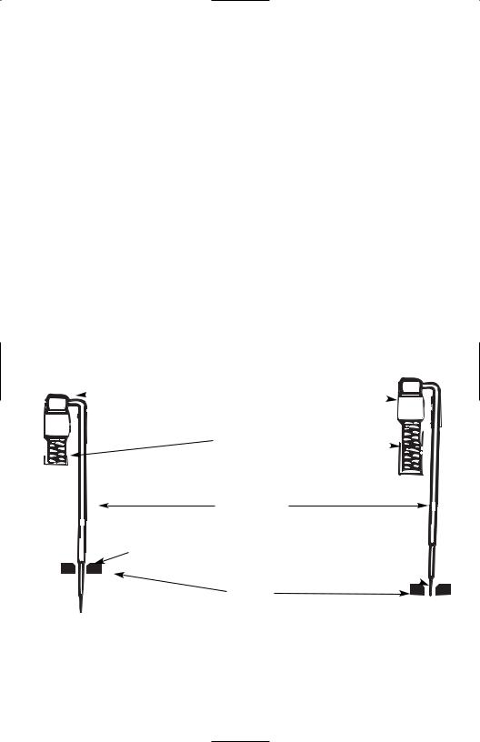
At higher engine loads, such as in a heavy part-throttle acceleration, there is a need for a richer mixture. This enrichment is provided by the Metering Rod and Step-Up Function (Figure 4). A vacuum passage (8) communicates the manifold vacuum to the underside of the Step-Up Piston (9). This vacuum tries to hold the Piston in the bottom of its bore by working against the force of the Step-Up Spring (10).
When the manifold vacuum is high, indicating a low load such as idle, cruise, or light acceleration, it is able to overcome the force of the Step-Up Spring and hold the Step-Up Piston at the bottom of its bore, which also positions the Metering Rod at the bottom of its travel. At this point, the Rod has a large diameter that creates a high restriction through the Jet and the fairly lean A/F Ratio that is desirable for low load/low power operation. This portion of the Metering Rod is referred to as the “Lean Step” of the Rod.
When the manifold vacuum is low, indicating a high load such as a heavy part-throttle (or WOT) acceleration, the Step-Up Spring is able to force the Piston to the top of its bore and position the Metering Rod at the top of its travel. This action is called “Power Mode Staging”. The portion of the rod now located in the jet has a smaller diameter, thus the restriction through the Jet is reduced and a rich A/F Ratio is provided for high load/high power operating conditions. This is the “Rich Step” of the Rod.
ROD DOWN: Lean A/F Ratio |
HIGH LOAD: Low Vacuum |
 Step-Up Piston
Step-Up Spring 
Metering Rod
LEAN STEP In Jet
RICH STEP In Jet
Main Jet
LOW LOAD: High Vacuum |
ROD UP: Rich A/F Ratio |
Metering Rod and Step-Up Function
Figure 4
5 Edelbrock Performer Series Carburetor Owner’s Manual 8/94
Secondary Main System: The Secondary Main System (Figure 5) delivers fuel only when the secondary throttle blades and air valve are open. It ensures that fuel delivery varies with air flow.
The Secondary Throttles (1) begin to open when the Primaries are about 65% open. The Primary and Secondary Throttles arrive at the WOT stop at the same time.
Air flow through the Secondary side is controlled by Air Valves (2). These valves are located in the secondary bores above the throttle blades. They are balanced against a counter weight and open to admit additional air flow only if there is enough air velocity to allow the proper operation of the Secondary Metering Systems.
The principles of operation for the Secondary Main System are the same as those that govern the operation of the Primary Main System; the pressure drop (suction) arises from the increase in the airs velocity as it passes through the Venturi sections. The pressure drop (suction) at the Secondary Booster Venturi (3) is communicated into the system by the Secondary Nozzle (4).
Fuel flows through the Secondary Main Jet (5) to the Secondary Well where it is drawn through the Secondary Well Tube (6). The fuel is mixed with air that enters the tube through a series of small holes. The source of the air is one of the Secondary Well Bleeds (7). There are two air-bleeds; one admits air to the outside of the Well Tube and the other allows air to flow into the passage behind the Nozzle. The fuel, now well mixed with air, flows through the slightly up-hill passage and exits into the Secondary Boost Venturi (3) through the Secondary Nozzle (4).
Secondary Main
Systems
Figure 5
|
|
(3) Secondary |
|
|
|
Boost |
|
(7) Secondary |
|
Venturi |
|
Well Bleeds |
(4) |
Secondary |
|
(2 bleeds) |
|||
|
Nozzle |
||
|
|
(6)Secondary Well Tube
(5) Secondary |
|
Main Jet |
(2) Air |
|
Valve |
(1)Secondary  Throttle
TRANSIENT CONTROL SYSTEMS
In addition to the three (3) basic Metering Systems, there are two (2) Transient Control Systems; The Secondary Auxiliary System and The Pump System.
Secondary Auxiliary System
During the initial stages of Secondary Operation, the air flow rate through the secondaries is very low. Accordingly, there is not enough pressure drop (suction) at the Secondary Nozzle to induce fuel flow. In order to prevent a lean A/F condition that would be experienced by the driver as a
6 Edelbrock Performer Series Carburetor Owner’s Manual 8/94
“bog” or “flat spot” on secondary opening, it is necessary to add fuel by an auxiliary means during the time the secondary is in the transient phase.
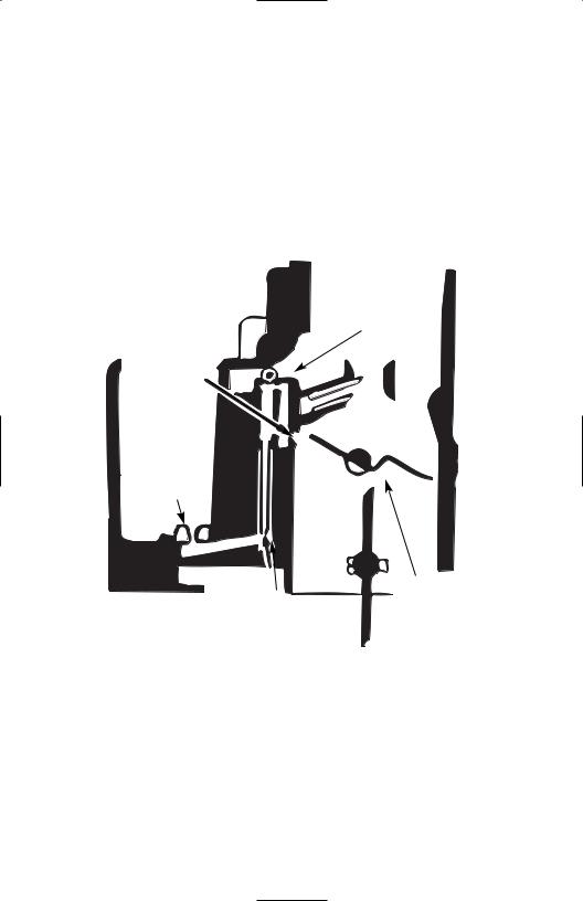
This is accomplished by placing a small Discharge Nozzle (2) at a point just under the Air Valve (1). The air flow past the edge of the Air Valve creates sufficient pressure drop to pull fuel out of the Auxiliary System. The fuel must first pass through the Secondary Main Jet (3) to the Secondary Well; it is then drawn through the Auxiliary Fuel Tube (4) and exits at the Discharge Nozzle (2). There is always an air-bleed, either in the Auxiliary Fuel Tube (near the top), or as a separate brass restriction bushing (shown).
The flow of fuel in the Auxiliary System is enough to prevent a lean transient on Secondary opening. As the Air Valve is opened further by increasing air flow, the fuel flow through this system decreases. Correspondingly, the fuel flow in the Secondary Main System increases, providing a near constant A/F Ratio.
(5) Air-Bleed
(some PNs)
(2) Discharge
Nozzle
(3)Secondary Main Jet
(4) Auxiliary |
(1) Air Valve |
Fuel Tube |
|
Secondary Auxiliary System
Figure 6
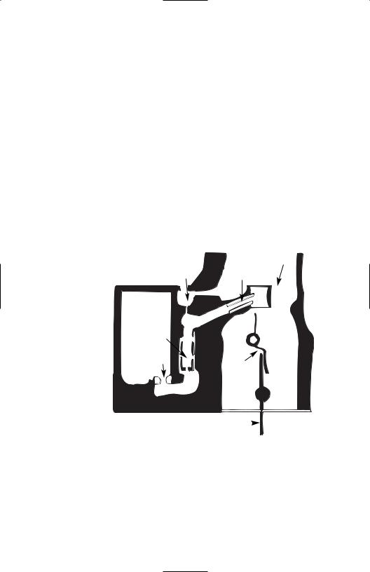
Pump System
When the throttle is opened rapidly, the air flow through the engine will increase immediately. The fuel, since it is much heavier than the air, will “lag” behind. This contributes to a temporary lean A/F condition. Regardless of cause, a solution is to temporarily enrichen the A/F Ratio by mechanically pumping a small quantity of fuel into the throat of the carburetor (Figure 7). The Edelbrock carburetor has a piston that draws fuel into the pump cavity past the plunger lip-seal when the throttle is closing
(1). Upon opening, the lip-seal seats, allowing the plunger to force the fuel through another one-way valve, the Pump Discharge Ball and Weight (2), and the Pump Jets (3) into the primary throats.
7 Edelbrock Performer Series Carburetor Owner’s Manual 8/94

The pump plunger is not driven directly by the throttle, but through an intermediate Pump Drive Spring
(4) that extends the duration of the “pump shot” past the time the throttle stops moving. The Edelbrock Performer Series carburetor has an external pump lever with three hole locations for link attachment providing three distinct pump delivery curves. This is further explained in “Calibrating The Pump”.
Pump
System
Figure 7
EXTERNAL DEVICES
(3) Pump Jets
(2) Pump Discharge Ball & Weight
(4) Pump Drive Spring
(1) Inlet Check
(Lip Seal)
The function of your Edelbrock Performer Series carburetor is also dependent on several external devices; the fuel pump and air cleaner.
Fuel Pumps and Pressure
Avoid extremes in fuel pressure. At IDLE, there should not be any more than 6.0 psi; if the vehicle has an adjustable fuel-pressure regulator, set it to 5.5 psi. With most fuel pumps the minimum fuel pressure is encountered at high rpm and WOT. Fuel pressure should not drop below 2.0 psi. If it does, a fuel pump with more capacity may be required. Note that some later model vehicles (the 5.0L Ford is one example) have mechanical pumps that will give more than 6.0 psi at idle. The vehicle will perform well, but may be prone to stalls on quick turns and stops with the clutch disengaged. If this problem occurs, check the fuel pressure. If it is more than 6.0 psi at IDLE, it should be reduced through the use of a regulator, such as Edelbrock #8190, or by creating a restricted by-pass bleed to the fuel return line. Edelbrock Street Fuel Pumps are highly recommended for all Edelbrock Performer Series carburetor installations.
Always use a filter, such as Edelbrock #8873 between the pump and carburetor. Note that a good filter is large in area, so it may be able to transmit a significant amount of heat to the fuel. It is a good practice to keep the filter away from heat and not allow it to come in contact with any part of the engine.
8 Edelbrock Performer Series Carburetor Owner’s Manual 8/94

Air Cleaners
Your Edelbrock carburetor was originally calibrated with a low restriction open element air cleaner configuration; a 14”x3” Edelbrock Signature Series unit. It was also evaluated for proper metering and vehicle performance using a variety of other air cleaner designs and will perform as intended with nearly any reasonable air cleaner design. While the Edelbrock Performer Series carburetor does not exhibit excessive sensitivity to the air cleaner, there are several guidelines you should follow when selecting an air cleaner:
•Running without an air cleaner is strongly discouraged for a street-driven vehicle. Dirt and varnish will accumulate in critical bleeds and upset the fuel metering. Dirt and debris may easily get into the fuel bowl through the bowl vents or larger bleeds and cause a multitude of problems.
•Any calibration testing should be performed with the air cleaner in place. Depending upon the air cleaner used, the metering typically will be leaner with the air cleaner in place.
—A large 14”x3” open element air cleaner, such as Edelbrock Elite Series, Signature Series and Pro-Flo air cleaners, offers almost no resistance to air flow. Flow bench results show virtually no reduction in air flow. Also, this design should cause no change to the fuel metering.
—A 10”x2” open element design will result in some definite air flow restriction but little change to the fuel metering.
—Elements smaller than 10”x2” are more restrictive and have the most effect upon metering. The fuel metering at WOT will be shifted LEANER, especially at higher rpm ranges.
•If you have a dual-purpose vehicle that is sometimes used in competition without an air cleaner, it may be necessary to have two separate calibrations. If you are running a smaller air cleaner and have optimized the WOT with it in place, do not be surprised to find that the metering shifts RICHER when the air cleaner is removed. This may require you to calibrate the WOT with leaner Jets and Rods at the drag strip.
•DO NOT allow the vehicle air-stream to blow across the top of the carburetor(s) such as on an open-bodied car or full-bodied vehicle with a tunnel-ram manifold. The flow of air across the carburetor will result in an upset to the fuel metering that cannot be accommodated by recalibration since the change to the A/F Ratio will be different for every vehicle speed.
SECTION 2 : TUNING PROCEDURE
Before proceeding please ensure you have installed your Edelbrock Performer Series Carburetor according to the Carburetor Installation Instructions included with the carburetor
REVISING THE CALIBRATION
The Edelbrock Performer Series Carburetor is designed to allow quick and easy changes to the metering. Virtually any change imaginable can be performed without removing the carburetor from the manifold, and the most common changes may be performed in less than five minutes without removal of the airhorn (bowl cover).
9 Edelbrock Performer Series Carburetor Owner’s Manual 8/94
To help you calibrate your carburetor, a CALIBRATION REFERENCE CHART has been designed for each model of the Edelbrock Performer Series carburetor. These charts (pages 18—31) each consist of two sections: A Calibration Table and a Rod/Jet Reference Chart.
After reading the Calibration procedures, the next step in calibrating your carburetor is to look at the Calibration Table for your model carburetor. Determine if you would like to go richer or leaner in the Cruise Mode and do the same for the Power Mode. Select the number that is closest to intersection of your Cruise and Power Mode selections. This is your calibration reference number. Now refer to the Rod/Jet Reference Chart that appears on the opposing page. Locate your calibration reference number to determine the rod/jet combination for your application.
For example, you have a 1405 Edelbrock Performer Series carburetor. You have determined (by reading the rest of the manual) you would like to go 1 stage lean in the Cruise Mode and 2 stages lean in the Power Mode. The intersection of these two lines lies on the number 21. This is your calibration reference number. Now look below the Calibration Table to the Rod/Jet Reference Chart. Find the number 21 under the REF# column. The jets you should use are .098 and the rods are .070 x .052.
Located at the very bottom of each Calibration Reference Chart is a guide for changing your Secondary Metering. This will be useful when calibrating the wide-open-throttle (WOT).
Before you attempt to establish a new calibration, be sure that the engine is in a sound state of tune. All ignition items must be in proper working order, including reasonably fresh plugs of the correct heat range. Timing should be properly set and the air filter element and fuel filter should be clean.
Proper fuel pressure should be verified and cracked or brittle vacuum lines should be eliminated. Many so-called “carburetor calibration” problems have been traced to another part of the engine system that was not functioning properly.
CAUTION: Be alert to carburetor flooding when fuel is first applied. Flooding can be caused by dirt, small particles of hose cuttings, floats and inlet needles which have settled during shipping, or by other conditions as discussed below. Each Edelbrock Performer Series carburetor is flow tested in the factory for both air and liquid flow so flooding is rare. However, for safety sake please observe this caution. When the fuel pump is turned on or when the engine is first started, watch closely for signs of flooding. If flooding is apparent, tap the body of the carburetor lightly with a rawhide mallet or the wooden handle of a small hammer. If flooding continues, pinch the fuel line hose to shut off flow, run the engine to clear the carburetor, and let the fuel line flow again. If flooding continues, pinch the fuel line hose to shut off flow, run the engine to clear the carburetor, and let the fuel line flow again. If flooding still continues, stop the engine. Clean up any raw gasoline and refer to the “Trouble Shooting” section of the Owner’s Manual.
Parts and Equipment —
Aside from ordinary hand tools, the following items are recommended.
•Edelbrock Performer Series Carburetor Jet Set - Contains selections of Main Jets, Metering Rods, and Springs.
•Tachometer - If the vehicle is not equipped with a tach, the dwell meter style tach will be adequate. If neither is available, you will be able to use the speedometer in place of the tach for some of the procedures, but it will not be as convenient.
•Vacuum Gauge - Should be hooked up to read engine’s intake manifold vacuum. Without a vacuum gauge, some of the calibration procedures will be more difficult.
10 Edelbrock Performer Series Carburetor Owner’s Manual 9/01

Changing Components
Metering Rod and Step-Up Spring changes can typically be made in less than five minutes and without removing the carburetor. First, loosen the Step-Up Piston Cover Screws (See pg. 32) and twist the Step-Up Piston Cover Plates to the side. The Metering Rods and Step-Up Springs can now be removed and replaced if necessary. Be sure to replace the Step-Up Piston Cover Plate and tighten the Step-Up Piston Cover Screw when finished. CAUTION: Do not overtighten the Step-Up Piston Cover Screws! They should only be tightened to 12 to 17 inch/pounds. Excessive torque will weaken or snap off the screw heads. If this happens, they may fall into the carb causing serious engine damage. If an inch/pound torque wrench is not available, snug the screw until it just touches the plate, then tighten 1/16th turn more.
To replace the Primary or Secondary Metering Jets, first, remove the Metering Rods and Step-Up Springs as outlined in the preceding paragraph. Next, disconnect the Choke Cam Connector Rod, Pump Connector Rod, and Choke Connector Rod (when applicable). Finally, remove the 8 Airhorn Attaching Screws and remove the Airhorn from the carburetor body. A standard screwdriver can now be used to remove the appropriate Metering Jets. Once desired Metering Jets have been installed the carb may be reassembled by reversing this procedure.
IDLE MIXTURE
The Edelbrock Performer Series carburetor has conventional Idle Mixture Screws (IMS) that provide a leaner A/F when turned clockwise and richer A/F when turned counter clockwise. The idle air flow is controlled by a conventional screw that opens the Primary Throttles. The following procedure should be used to set the idle mixture and speeds.
1.Fully warm engine and ensure choke is fully open.
2.Air cleaner in place.
3.Set desired speed with the air screw.
4.Adjust the IMS on ONE side to get the maximum possible RPM. Do not go rich beyond the maximum speed point.
5.If the above changed the idle speed more than 40 RPM, then readjust the speed.
6.Adjust the side OPPOSITE of that in Step 4 to get maximum RPM.
7.Reset the speed.
8.Carefully trim each IMS to again get the maximum idle RPM.
9.Go leaner just enough to get a 20 RPM drop in speed.
10.Reset the speed to the desired RPM.
11.This is a Lean-Best Idle Set. Setting richer than this will not improve idle quality or performance, but could tend to foul plugs.
Winter Fuel Idle Sets
During the winter months (in most parts of the country) the local fuel will be a “winter” blend that is very volatile, as an assist to cold-engine starting and driveability during warm-up. However, the high volatility has the disadvantage of allowing excessive vaporization of the fuel if the vehicle is operated in a heated area such as a garage. This can result in problems in the idle-set procedures since the carburetor’s internal vents will allow this excess vapor to be drawn into the throats and enrichen the mixture. The idle will be erratic and not seem to be able to hold a set. To resolve this type of problem, it is advisable to perform the final settings outdoors after the vehicle has been stabilized with a drive of several miles.
11 Edelbrock Performer Series Carburetor Owner’s Manual 9/01

Long Duration Camshaft
If the engine has a fairly radical camshaft it may require an excessive amount of throttle opening for idle and/or have low idle vacuum levels. Either condition can lead to poor levels of adjustability and erratic idles.
•Another fix for the above condition is to run as much spark advance as possible at idle. If the distributor is fitted with a vacuum advance unit, connect it directly to manifold vacuum. If you are not able to employ vacuum advance for some reason, then the mechanical curve should have a low limit, which will allow you to use plenty of initial spark advance.
•Measure the manifold vacuum at idle. If it is below 7” Hg, there is a good chance that the Metering Rods are in the up (rich) position. When combined with a high idle air rate this can cause the Nozzles to discharge fuel at idle. Use a weaker Step-Up Spring (see section on StepUp calibration) to keep the Rods down at idle. With some cams, a stiffer spring (pink or silver) is necessary. Experimentation is the best way to determine which is best for your application.
CALIBRATING THE WIDE-OPEN-THROTTLE (WOT)
The best place to perform your WOT calibration is on a chassis dyno. If one is not available then consider a safe, legal driving space, such as a drag strip where you are given E.T. and MPH data.
1.Select an RPM Range to use in evaluating the WOT power. As a rule, use the highest 50 percent of the real power band. If your engine makes good power up to 5000 RPM, then 2500-5000 is a good range. If peak power is at 6500, then 3500-6500 would be a good pick. Be sure not to select RPMs that are higher than the engine’s useful power band.
2.Accelerate at WOT from 1000 RPM below the range you have elected to a few hundred over the range. Time the acceleration with a stop-watch. Be sure to time only the interval while the engine is sweeping through the selected range. Make enough timed accelerations to get a good average that is not affected by wind or grade.
3.Refer to the Calibration Reference Chart for your model. Find the richest Power Mode (Primary Metering) change you can make without changing a Jet — a Rod change only. This will probably be 2 stages (8%) rich.
4.Change to the indicated Rods. Perform timed acceleration #2. Compare the times. Do not be surprised if there is no difference.
5.Compare the results of timed acceleration #2 to the base calibration and refer to the following section that best describes your situation:
Case 1: Faster than base calibration
Change Secondaries 2 stages richer and perform acceleration test #3.
•If test #3 is the same as #2, you’re done.
•If test #3 is slower than #2, change to 1 stage rich for the Primary and Secondary and you’re done.
•If test #3 is still faster than #2, go to 3 stages rich Primary and Secondary and keep going richer until there is no change (or slower) in the times. Stay at the first “no change” level, so that you stay with the richer of any two levels of calibration that have the same power.
12 Edelbrock Performer Series Carburetor Owner’s Manual 8/94
 Loading...