

Getting Started with
TSC AMIGO2
Evolving ACFM
User’s
Manual

© Eddy NDT, Inc.
3425 Pierre-Ardouin Québec (QC)
G1P 0B3 CANADA
Eddy NDT, Inc. ACFM, Ami go, Sensu, TSC, and their a ssociated lo gos are trademark s or registered trad emarks of Technical S oftware Con sultants Ltd. (wholly
owned sub sidiary of Edd y NDT, Inc.) in the United Kingdom and/or oth er countries. Edd y Technologi es reserves th e right to change product oerin gs and
specications without notice.
2019-01-14
2 | www.eddy.com

Contents
General Precautions and Conventions
General Precautions ii
Safety Precautions ii
Rear Stand ii
Conventions iii
Typographical iii
Marking and Symbols iii
Safety Indications in This Document iv
Acronyms iv
EMC Directive Compliance iv
FCC Compliance (USA) iv
ICES Compliance (Canada) iv
AS/NZS Compliance (Australia/New Zealand) v
CE Compliance (EU) v
Radio Power Rating v
Calibration and Warranty Seals v
Limited Warranty vi
Copyrights vi
System Overview
Introducing the Amigo2 System 2
What is in the Box 2
Instrument Overview 2
Positioning Amigo2 7
Starting Amigo2 8
Probe Connection 8
Batteries 8
Inserting/Removing Batteries 9
Hot Swapping Batteries 9
Charging Batteries 9
Calibrating Batteries 10
Storing Batteries 10
Software Overview
Introduction 13
Backstage 13
General Section 13
Probe Selection 14
File Transfer 15
View Imported 15
Documentation Section 16
Preference Section 16
Help Section 17
| i

Frontstage Layout 18
Pinning Dialogue Boxes 19
Information bar & warnings 20
The Home Ribbon 21
The Scanning Ribbon 22
Conguring Markers 23
Origin Dialogue Box 24
Row Visibility Dialogue Box 24
The Analysis Ribbon 25
Sizing a Defect 26
Defect Dialogue Box 27
Adding a Region 28
Regions Dialogue Box 28
Creating an Automated Report 29
Standard Layout 30
Layout 2 31
Layout 3 31
Layout 4 32
Layout 5 32
Manipulating Data Through Touch 33
Preferences
Managing Preferences 35
Measurement Units 35
Company Logo 35
Adjusting the Date and Time of the Amigo2 Instrument 36
Keypad and Keyboard Functions
Keyboard Shortcut Keys 40
Modifying Keyboard Shortcuts 41
Maintenance and Troubleshooting
Maintaining Amigo2 43
Cleaning Amigo2 43
Updating and Upgrading Software 43
Standard 43
System Recovery 45
Troubleshooting 47
Specications
General 50
Connector Reference
I/O Connector 53
ii | www.eddy.com
Activating Windows 46
Known Issue With System Updates/Upgrades 46
Troubleshooting System Updates/Upgrades 47

Ethernet Connector 53
HDMI Connector 54
Audio Jack 55
Using the optional Harness
Adjusting the Harness 58
Adjusting the Harness to your Body 58
| iii

Figures
Figure 3-1 Front view 2
Figure 3-2 Rear view 4
Figure 3-3 Right side view 5
Figure 3-4 Left side view 6
Figure 3-5 Amigo2 in horizontal position 7
Figure 3-6 Amigo2 in tilted position 7
Figure 3-7 Optional battery charger 9
Figure 4-1 Backstage view: General 13
Figure 4-2 Probe selection 14
Figure 4-3 View imported probes 15
Figure 4-4 Backstage view: Documentation 16
Figure 4-5 Backstage view: Preferences/System 16
Figure 4-6 Backstage view: Preferences/Display 17
Figure 4-7 Backstage view: Help 17
Figure 4-8 Frontstage layout 18
Figure 4-9 Screenshot of Frontstage 18
Figure 4-10 Pin icon 19
Figure 4-11 Information bar & warnings 20
Figure 4-12 The Home Ribbon 21
Figure 4-13 Coating thickness dialogue box 22
Figure 4-14 Scanning ribbon 22
Figure 4-15 Marker setup dialogue box 23
Figure 4-16 Rows dialogue box 24
Figure 4-17 Rows dialogue box 24
Figure 4-18 The Analysis Ribbon 25
Figure 4-19 The Replay Ribbon 25
Figure 4-20 Sizing 26
Figure 4-21 Defects dialogue box 27
Figure 4-22 Adding a region 28
Figure 4-23 Regions dialogue box 28
Figure 4-24 The Analysis Ribbon 29
Figure 4-25 The layout ribbon 29
Figure 4-26 Standard view 30
Figure 4-27 Layout 2 31
Figure 4-28 Layout 3 31
Figure 4-29 Layout 4 32
Figure 4-30 Layout 5 32
Figure 3-1 System preferences 35
Figure 3-2 Selecting a logo 35
Figure 3-3 System preferences 36
Figure 3-4 Wi-Fi Networks dialog box 36
iv | www.eddy.com

Figure 3-5 Display preferences 37
Figure 4-1 Keyboard Shortcuts 41
Figure 5-1 Update dialog box 44
Figure 5-2 Options menu 45
Figure 5-3 System recovery interface 45
Figure 8-1 Slipping the harness on 58
Figure 8-2 Adjusting the shoulder straps 59
Figure 8-3 Adjusting the belt’s height 59
Figure 8-4 Securing the chest straps 60
Figure 8-5 Securing the belt 60
Figure 8-6 Shoulder anchor straps 61
Figure 8-7 Unfastening the straps 61
Figure 8-8 Sliding strap loop through bumper hook 62
Figure 8-9 Securing anchor strap 62
Figure 8-10 Alternative method of securing anchor strap to bumper 62
Figure 8-11 Anchor strap on harness belt 63
Figure 8-12 Slipping male buckle through bumper 63
Figure 8-13 Mating battery compartment side anchor strap 64
Figure 8-14 Closing battery compartment door. 64
Figure 8-15 Mating shoulder anchor strap 65
Figure 8-16 Tightening shoulder anchor straps 65
Figure 8-17 Belt-slinging probe cable 65
Tables
Table 4-1 Keyboard shortcut 40
Table 6-1 General specications Environmental 50
Table 6-2 Environmental specications 50
Table 7-1 I/O connector data 53
Table 7-2 I/O connector pinout 53
Table 7-3 Ethernet connector data 53
Table 7-4 Ethernet connector pinout 54
Table 7-5 HDMI connector data 54
Table 7-6 USB connector data 55
Table 7-7 USB connector pinout 55
Table 7-8 Audio jack data 55
Table 7-9 Audio jack pinout 55
| v

General Precautions and Conventions

General Precautions and Conventions
General Precautions
The following safety precautions are to be observed at all times when using Amigo2®.
Make sure that you review them before turning on the system.
Keep this document in a safe place for future reference.
Carefully follow the installation and operation procedures detailed herein.
Respect the safety warnings on the instrument and in this document.
Amigo2 should only be used by certied personnel.
When transporting Amigo2, it is your responsibility to make sure that you apply the safety
precautions dictated by the relevant local governing bodies.
Always connect the power supply to a properly grounded receptacle, extension cord, or
power bar. Grounding a single conductor of a two-conductor outlet is not sucient
protection for Amigo2.
Only connect the system to a power source corresponding to the type indicated on the
rating plate.
If you use the system in a manner that deviates from the one specied by Eddy, the
protection provided on the equipment may be rendered null and void.
Do not use substitute parts or perform unauthorized modications to the system.
Service instructions, when applicable, are intended for trained service personnel only.
Always make sure that the system is unplugged from any power supply before servicing.
To avoid a dangerous electric shock, do not perform any service on the system unless
trained to do so. If you encounter any problems or have questions regarding this system,
contact Eddy or an authorized Eddy representative.
Safety Precautions
Observe the following safety precautions scrupulously when using Amigo2.
Rear Stand
Because Amigo2 is a portable system, it is designed to be used under tough conditions. It is,
however, not indestructible. To avoid damaging Amigo2, use its rear stand when operating
Amigo2 in a tilted position. Do not use Amigo2 in the upright position, as it may topple over or
fall o the work surface.
ii | www.eddy.com
General Precautions and Conventions
Conventions
Typographical
The following typographical conventions are used throughout this document:
Italic
Used for le names and paths.
Bold
Used to indicate menu items, named user interfaces, and place emphasis on specic words or
phrases. Items in bold type are capitalized to reect the actual interface.
SMALL CAPITALS
Used to indicate instrument interface indications.
Marking and Symbols
The following symbols appear on the instrument and pertain to safety regulations that should
be carefully observed:
This label is used as a general warning sign. It indicates that you should refer to this
user’s guide to obtain the necessary information for proper protection of the
instrument and its users.
This label is used to indicate high voltage. It draws your attention to the presence
of hazardous voltages (within the product enclosure or accessible externally) that
may constitute a risk of electric shock to persons. Always refer to the user’s guide
to ensure proper protection and safety.
The RoHS compliance logo signies that this product complies with the Restriction
of Hazardous Substances directive 2002/95/EC. This directive restricts the use of
lead, mercury, cadmium, hexavalent chromium, polybrominated biphenyl, and
polybrominated diphenyl ether in certain classes of electrical and electronic units
as of July 1, 2006.
This label acts as a reminder that you should dispose of this system in accordance
with your local Waste Electrical and Electronic Equipment (WEEE) regulations. This
system was manufactured to the high-quality standards of Eddy to ensure safe
and reliable operation when it is used as stated in this document. Due to its nature,
this instrument may contain small quantities of substances known to be hazardous
to the environment and to human health if released in the environment. As such,
systems falling under WEEE regulations should not be disposed of in the public waste
stream.
| iii
General Precautions and Conventions
Safety Indications in This Document
The safety indications in this document are intended to ensure your safety and the integrity of
the system.
WARNING!
CAUTION
Important
Calls attention to important information in order to complete the tasks.
Note
Calls attention to an operating procedure, a practice, or the like that requires special attention.
Notes also indicate useful related information, but the parenthetical information is not
mandatory.
Warning
The warning indication calls your attention to a procedure or a practice (or the
like) that, if performed incorrectly, can result in injury. Do not ignore warning
indications make sure that you understand the condition before proceeding.
Caution
The caution indication calls your attention to a procedure or practice (or the
like) that, if performed incorrectly, can result in material damage, loss of data,
or both. Do not ignore caution indications make sure that you understand the
condition before proceeding.
Acronyms
ACFM: Alternating current eld measurement
HAZ: Heat aected zone
UI: User interface
A/C: Anticlockwise/Clockwise
T: Transverse
Fe: Ferrous
EMC Directive Compliance
FCC Compliance (USA)
This equipment was tested and found to comply with the limits for a Class A digital device,
pursuant Part 15 of the FCC Rules. These limits are designed to provide reasonable protection
against harmful interference when the equipment is operated in a commercial environment.
This equipment generates, uses, and can radiate radio frequency energy and, if not installed
and used in accordance with the user’s guide, may cause harmful interference to radio
communications. Operation of this equipment in a residential area is likely to cause harmful
interference in which case you will be required to correct the interference at your own expense.
ICES Compliance (Canada)
This ISM device complies with Canadian ICES-001.
iv | www.eddy.com

General Precautions and Conventions
AS/NZS Compliance (Australia/New Zealand)
This device complies with Australia and New Zealand AS/NZS 4252.2 (IEC 61000-6-4) and
AS/NZS 61000-6-2 (IEC 61000-6-2).
CE Compliance (EU)
The simplied EU declaration of conformity referred to in Article 10(9) shall be provided as
follows:
Hereby, Eddy declares the radio equipment type Amigo2 is in compliance with the Directive
2014/53/EU. The full text of the EU declaration of conformity is available at: https://www.
tscndt.com/wp-content/uploads/2018/12/AMIGO2-CE-Cercate-2018-12-17.pdf.
Radio Power Rating
2.4000–2.4835 GHz, max. 100 mW
The low band 5.15–5.35 GHz is for indoor use only.
Calibration and Warranty Seals
The calibration seal is at the back of the instrument. Amigo2 is also equipped with a warranty
seal.
Important
Broken seals void the calibration certication and product warranty.
| v

General Precautions and Conventions
Limited Warranty
Eddy NDT, Inc. warrants the hardware to be free of any defects in materials or workmanship
for a period of twelve (12) months from the date of delivery, under normal use and service. These
warranties are limited to the original purchase of the product and are not transferable.
Eddy NDT, Inc. will repair or replace any product component or documentation, at its option
and at no additional charge if found defective within the warranty period. The purchaser is
responsible for returning the product to Eddy NDT, Inc.
Eddy NDT, Inc., will not be held responsible in any way whatsoever for damage resulting from
improper installation, accident, misuse, or from service or modication of the product by anyone
other than Eddy NDT, Inc., or an authorized Eddy NDT, Inc. service center.
Eddy NDT, Inc. will not be held responsible in any way whatsoever for direct, indirect, special,
incidental, or consequential damages resulting from possession, use, improper installation,
accident, service, modication, or malfunction of the product (including, without limitation,
damages for loss of business prots, business interruption, loss of business information, or other
pecuniary loss). Eddy’s total shall in no event exceed the purchase price of the applicable
item(s).
This warranty is in lieu of all other warranties, whether oral, written, expressed, or implied,
including any warranty of merchantability or tness for a particular purpose, and no other
representation or claims of any nature shall be binding on or obligate Eddy NDT, Inc.
This agreement is governed by the laws of the province of Québec, Canada. Each of the parties
hereto irrevocably attorns to the jurisdiction of the courts of the province of Québec and further
agrees to commence any litigation which may arise hereunder in the courts located in the
judicial district of Québec.
Copyrights
This document and the product and programs it describes are protected by the Copyright Act
of Canada, by laws of other countries, and by international treaties, and therefore may not be
reproduced, in whole or in part, whether for sale or not, without prior written consent from
Eddy NDT, Inc. Under copyright law, copying includes translation in other languages and
formats.
© Eddy NDT Inc., 2019
This document was prepared with particular attention to usage to ensure the accuracy of the
information it contains. It corresponds to the version of the product manufactured prior to the
date appearing on the back cover. There may, however, be some dierences between this
document and the product if the product was modied after publication.
The information contained in this document is subject to change without notice.
vi | www.eddy.com

General Precautions and Conventions
| vii

Chapter 1
System Overview
System Overview
Introducing the Amigo2 System
Thank you for purchasing the Eddy® Amigo2® system. This chapter oers an overview of the
system, its components, and probes.
What is in the Box
Amigo2 comes with the following standard accessories:
Two high-capacity batteries
One power adapter (100–240 V)
Power cords
User documentation
Stylus
Transport case
Function check plate
Instrument Overview
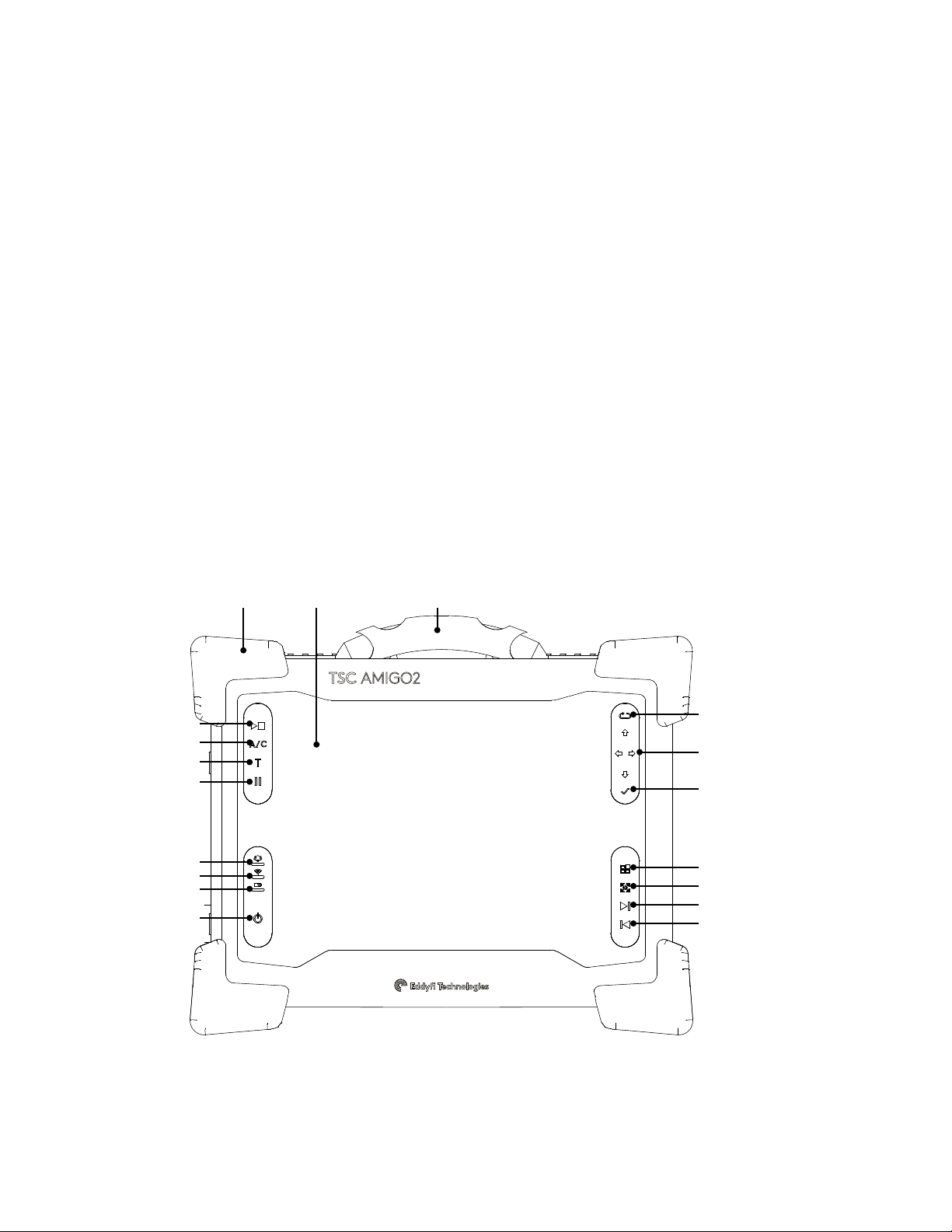
Front
Figure 3-1 Front view
9 10 11
8
7
6
5
4
3
2
1
12
13
14
15
16
17
18
2 | www.eddy.com

System Overview
1. Power button
Short press (approximately 0.5 to 4
seconds):
Use to turn the instrument on and o.
The power indicator at the center of the
button behaves as follows:
Green: Amigo2 is on
Blinking yellow/orange: Amigo2 is on
standby
Unlit: Amigo2 is o
Long press (approximately greater than
4 seconds)
If the instrument is on, a long press will
initiate a forced shutdown.
If the instrument is o, a long press will
activate RDAU mode, which allows the
user to operate the instrument remotely
from a laptop. Press and hold the power
button until the alarm indicator light
ashes, then release the power button.
The power button light will continue to
ash while in RDAU mode.
2. Battery indicator
Displays the state of the batteries when
the instrument is on. Depending on the
power mode (DC or battery), the
indicator behaves dierently:
DC power
Green: batteries fully charged
Blinking green: batteries charging
Red: battery or charger error
Unlit: no batteries
Battery power
Unlit: remaining charge over 40%
Orange: remaining charge 20–40%
Blinking yellow: remaining charge
less than 20%
Red: battery error
5. Pause
Pause data collection.
6. Transverse scan direction
Change the scan direction to transverse.
Pressing this key while data collection is
in progress adds general marks.
7. A/C Scan direction
Toggle scan direction between clockwise
and anticlockwise. Pressing this key
while data collection is in progress adds
clock marks.
8. Start/Stop acquisition button
Use to start or stop data acquisition.
9. Heavy-duty bumpers
The four corner bumpers provide shock
absorption and support Amigo2 at an
angle when it is set on a at surface. The
bumpers are also hooked for harnessing.
10. Multi-touch display
10.4”, non-reective, backlit,
high-resolution display.
11. Handle
Use this handle to carry Amigo2.
12. Keypad arrow mode
selection/Disable
touchscreen button
A long press disables the touchscreen.
Short presses toggle through the keypad
modes depending on the active view.
13. Keypad arrows
Use these arrows to navigate the Amigo2
software interface according to the
selected mode.
14. Enter button
Enter key. Closes text boxes.
15. Change active view button
Selects Bx, buttery plot, Bz or
information pane.
3. Wi-Fi indicator
Displays the Wi-Fi status. When the
indicator is lit, the Wi-Fi is enabled.
When it is o, the Wi-Fi is disabled.
4. Alarm indicator
Used to display user-programmed errors.
The indicator remains unlit until it
detects a predened error condition, at
which time it lights red.
16. Cycle through scale modes
Short press cycles through scale modes:
centered, auto-fit and default. Long
press will switch to manual scale mode.
17. Next page
18. Previous page
| 3
System Overview
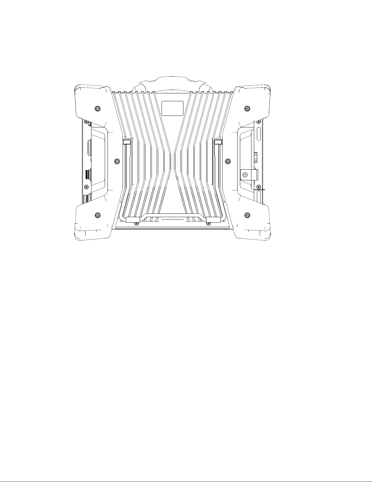
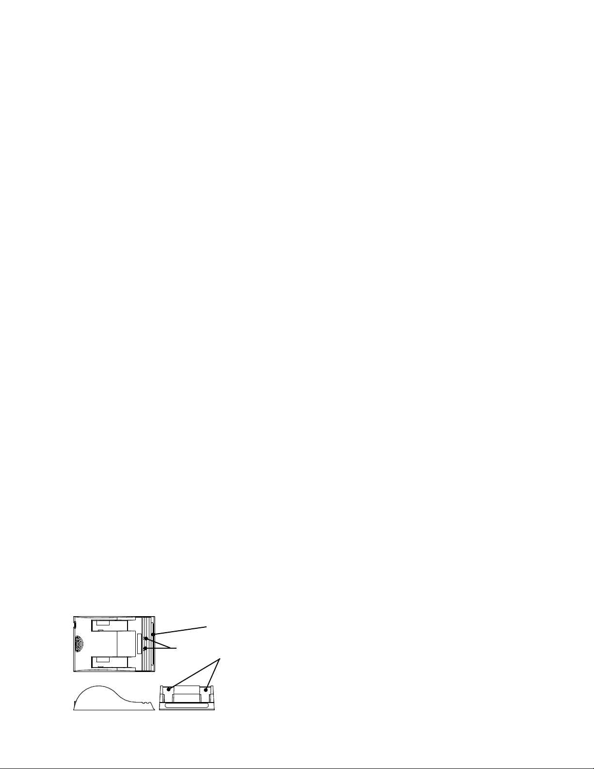
Rear
Figure 3-2 Rear view
1. Instrument stand
The stand retracts outward to hold Amigo2 at an angle, preventing the instrument from
tilting over horizontally.
4 | www.eddy.com
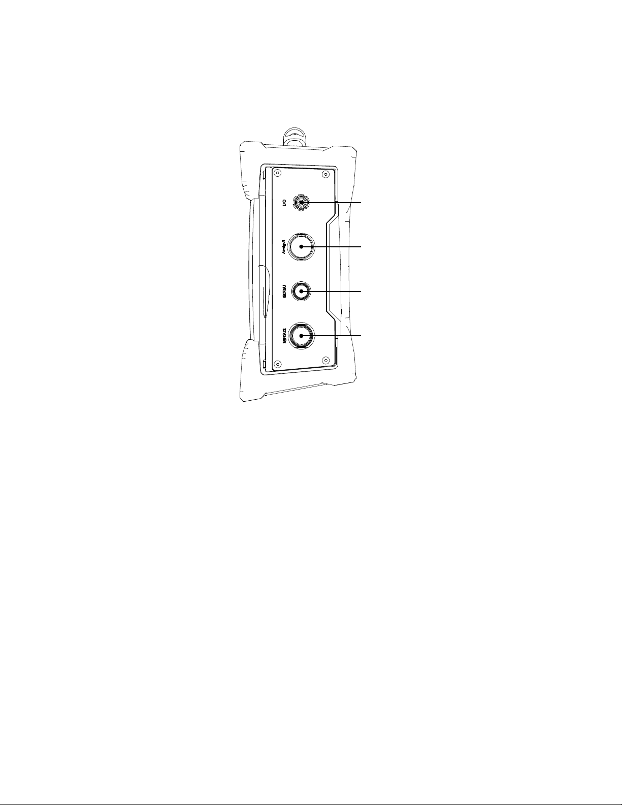
Right
Figure 3-3 Right side view
System Overview
1
2
3
4
1. I/O connector
Used to communicate with external encoders, for example.
2. Amigo1 connector
Used to connect with Amigo1 legacy probes, including arrays.
3. Sensu probe connector (PACE probes)
Used to connect with Sensu probes, typically supplied with the PACE instrument.
4. Second generation Sensu2 connector
Used to connect with second generation Sensu2 probes.
| 5
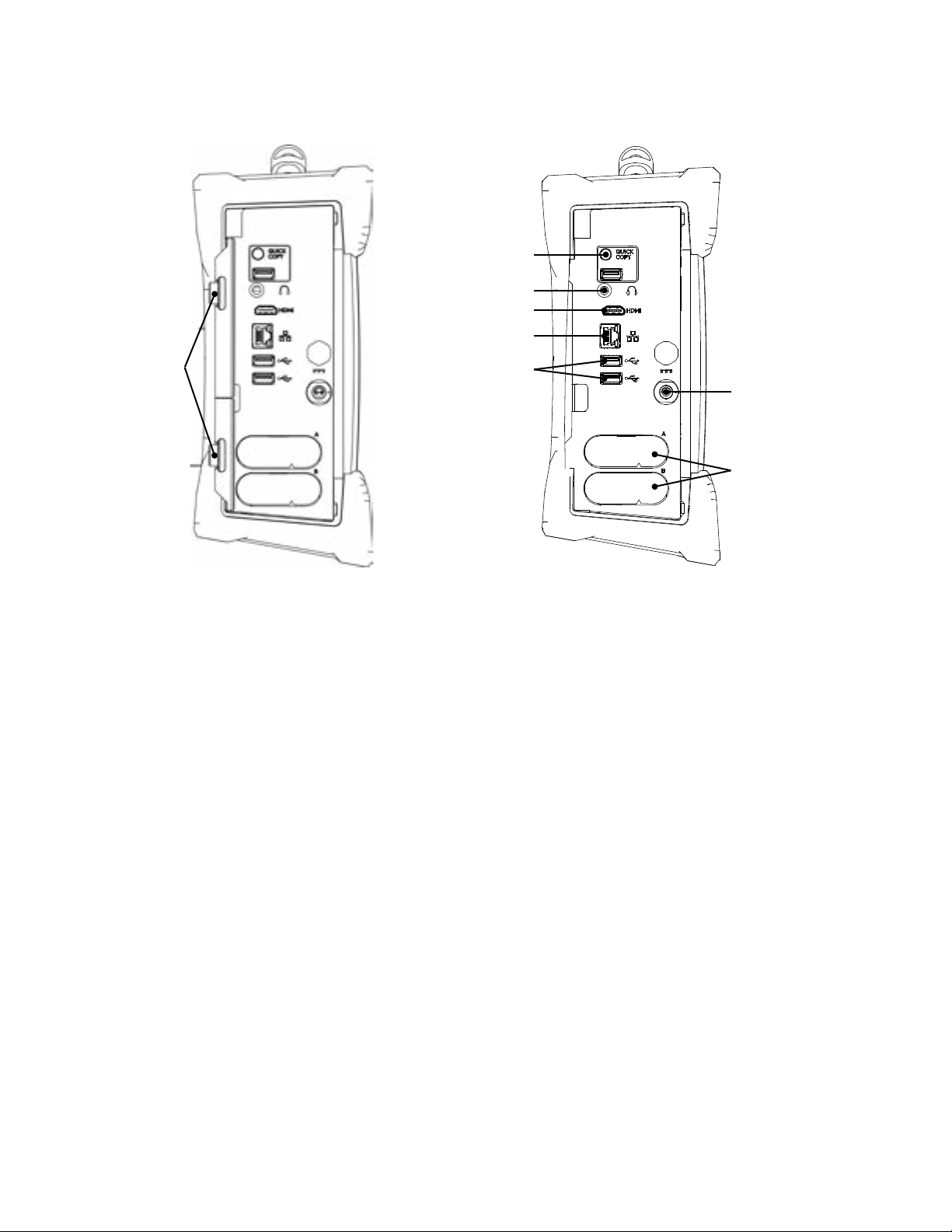
System Overview
Figure 3-4 Left side view
2
3
4
5
1
1. Protective connector door
Protects the Amigo2 connectors from
the elements when they are unused.
2. Quick Copy
Use to transfer all your inspection data
to a USB mass storage device and import
data from the USB mass storage device's
UserData folder.
3. Audio connector
Use to plug a headset to Amigo2.
®
4. HDMI
connector
Use to connect an external monitor to
Amigo2.
5. Network connector
Use to connect Amigo2 to a local area
network (LAN), also allowing remote
RDAU operation. The connector is
equipped with two indicators with the
following behaviors:
Connection indicator (upper)
Green: communication established
with the network
Blinking green: activity between
Amigo2 and the network
Unlit: no link to the network
6
7
8 9
Connection speed indicator (lower)
Amber: operating as a gigabit
connection (1 Gbps)
Green: operating as a 100 Mbps
connection
O: operating as a 10 Mbps
connection
6. USB 2.0 connectors
Use to connect USB devices to Amigo2
such as a mouse or an external disk
drive.
7. Power connector
Use the supplied power cord to operate
Amigo2 and recharge its batteries.
8. Battery compartments
Insert the supplied batteries into the
compartments. For details about
batteries, see page 6
9. Protective battery compartment
door
Protects the battery compartments
from the elements.
6 | www.eddy.com
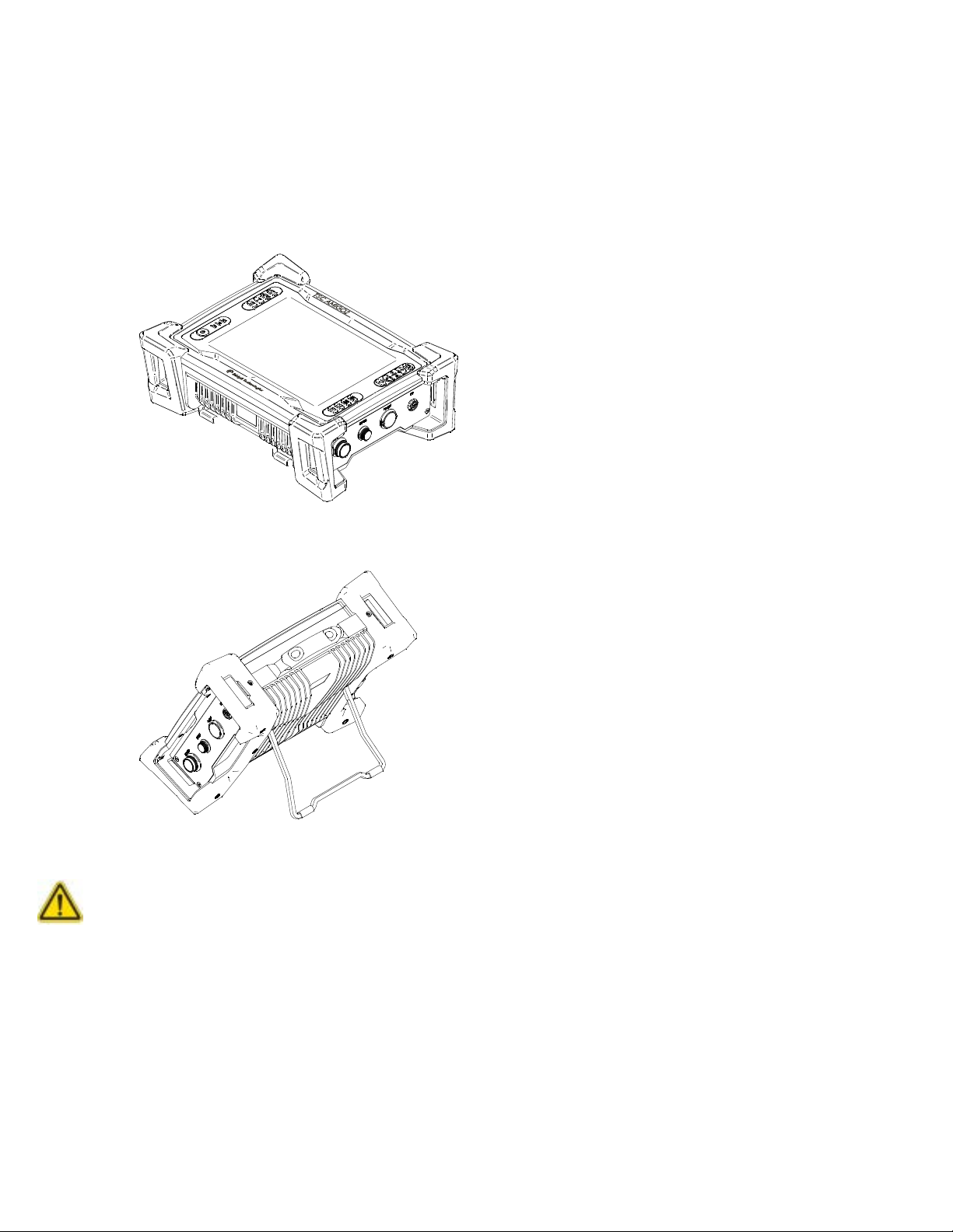
Positioning Amigo2
Amigo2 must be properly positioned prior to use so that you do not run the risk of dropping the
instrument or the instrument falling over. Amigo2 has two safe operating positions: horizontal
and tilted. To use it in a tilted position, simply pull out the stand located at the rear of the
instrument until Amigo2 is at the desired angle. If you are using Amigo2 with the optional
harness, see Adjusting the Harness on page 7 for details.
Figure 3-5 Amigo2 in horizontal position
System Overview
CAUTION
Figure 3-6 Amigo2 in tilted position
Caution
It is possible to use Amigo2 while it rests on its lower bumpers, but this is not a safe operational
position as the instrument may fall over. If you want to use Amigo2 at an angle, use the stand
located at the rear of the instrument.
Important
Regardless of how you position the instrument, you must always have a minimum clearance of
10 cm (4 in) on all sides of the instrument. Always position the instrument away from heat
sources. This ensures proper heat dissipation while the instrument is in use.
| 7

System Overview
Starting Amigo2
Proceed as follows to turn on your instrument or exit the standby mode:
1. Make sure that at least one of the two batteries is inserted into the battery
2. Press the power button.
Probe Connection
The Amigo2 has four connectors running down the righthand side of the instrument. The top
connector is the I/O port, while the lower three connectors are for attaching probes. Three
probes can be connected to the instrument, but only one of them can be used at any one time.
The top two connectors are push t Limo connectors. To make a connection, align the two red
dots and push the plug in until it clicks. To remove the connector, grasp the metal collar and
pull. This releases a catch that would otherwise hold the connector in place. Pulling on the cable,
rather than the metal collar, will severely damage the probe.
The lower two connectors are ratchet connectors. To attach these connectors, align the mating
lugs and screw the outer collar clockwise until the red ring, around the base of the connector,
is no longer visible and the mate is secure.
compartment A of the instrument or that the instrument is plugged in to an external
power source using the supplied power cord.
The power indicator at the center of the power button lights green.
WARNING!
Batteries
Amigo2 can be used under battery power. The instrument is designed with two battery cradles
under the protective battery compartment door but can be powered by a single battery. Amigo2
uses Li204SX-7800 lithium-ion rechargeable batteries from Emerging Power, which do not suer
from the memory eect aecting previous generations of batteries.
Warning
Whenever carrying Amigo2 in its transport case, remove the batteries from the instrument and
make sure that they cannot come in contact during transport, as this poses a signicant re
and explosion hazard.
When carrying Amigo2, it is the user’s responsibility to make sure that the safety precautions
used are in accordance with the local department of transportation (or equivalent governing
body) rules and regulations.
Amigo2’s transport case comes with two slots, tted to receive the batteries when removed
from the instrument.
Note
Make sure that you do not replace the batteries by batteries other than Li204X-7800 lithium-ion
rechargeable batteries from Emerging Power. Contact your Eddy representative for more
information about pricing and availability or replacement batteries.
8 | www.eddy.com
Inserting/Removing Batteries
Inserting Batteries
1. On Amigo2’s left side, unlatch the battery compartment’s door, and then open it.
2. Align your battery with one of the battery cradles.
Note
Battery cradles are marked A and B. If you are inserting only one battery, it does not matter
which of the two cradles you use.
3. Make sure that the battery contacts are facing inward and upward.
4. Slide the battery into the battery cradle until it is fully inserted. You should feel the
battery contacts snap into place.
Removing Batteries
1. On the left side of Amigo2, unlatch the battery compartment’s door, and then open it.
2. Grab the battery tab between thumb and forenger.
3. Pull on the tab.
You will feel the battery contacts being released.
4. Slide the battery out of its cradle.
System Overview
Hot Swapping Batteries
You can remove one of the Amigo2 batteries when the instrument is turned on as Amigo2 can
operate with a single battery. Should the power in the remaining battery be insucient to keep
Amigo2 operating, the instrument shuts down without damaging electronic components, but
all your work in progress in the Amigo2 software (acquisition, etc.) is lost.
Charging Batteries
Note
Batteries do not recharge when their internal temperature exceeds 45 °C (113 °F). Batteries also
do not power Amigo2 when the instrument’s internal temperature exceeds 55 °C (131 °F).
Using the Optional Battery Charger
An optional battery charger is available from Eddy. Contact your Eddy representative for
more information about pricing and availability. This charger conditions and calibrates the
instrument’s batteries, which is important to maximize their lives. We recommend calibrating
the batteries every six months.
Figure 3-7 Optional battery charger
Status window
Calibration buttons
Battery slots
| 9

System Overview
To charge the batteries with the optional charger:
1. Place the charger on a at and level surface, away from heat and moisture sources.
2. Insert the power supply’s DC connector into the back of the external charger.
3. Connect the power supply to an AC supply using the supplied cable. All the LEDs ash
4. Insert the batteries into the battery slots while making sure that the contacts are fully
Calibrating Batteries
To ensure that your batteries perform at their full capacity for the longest possible time, it is
important to calibrate them on a regular basis. Calibration involves a standard battery charge
followed by a deep discharge, and then a complete charge. This procedure usually takes 10 to
13 hours, whereas a standard charge only takes approximately 3.5 hours.
Calibrate batteries by placing them in the optional charger and then pressing the calibration
button. We recommend calibrating your batteries at least every six months.
momentarily to let you know that power is present.
seated.
The charger automatically begins charging the batteries and the LEDs in the status window
display the following information:
Blinking green: battery charging
Green: battery fully charged
Blinking blue: battery calibrating
Blue: battery charge gauge calibrated
Blinking red: battery charge gauge in need of calibration
Red: error
Storing Batteries
Whenever transporting Amigo2 in its case, remove the batteries from the instrument, place
them in plastic bags, and then make sure that they cannot come in contact during transport,
as this is a signicant re and explosion hazard. Amigo2’s transport case is outtted with two
slots intended for the batteries. We recommend that you take advantage of them.
10 | www.eddy.com


Chapter 2
Software Overview

Introduction
The Amigo2 runs the latest version of TSC’s ACFM data collection and analysis software, known
as Assist 3. Assist 3 is split into the frontstage and backstage. The frontstage is used to collect
and analyse ACFM data. The backstage is primarily used to enter job details, manage probe
congurations, settings and les. The software opens on the backstage.
Pressing either the blue or red arrow button at the top left of the screen toggles between the
two. Pressing the Start/Resume button at the bottom of the backstage screen also takes the
user from the backstage to the frontstage.
Backstage
The backstage consists of four tabs running down the left-hand side.
General. Enter job details, import and export data, manage probe conguration les, etc.
Documentation. View PDF documents relating to the software.
Preferences. Change system settings, units, time and date, connect to wireless networks,
etc.
Help. Software, rmware versions and license information, etc.
The four sections are described in more detail, below.
Software Overview
General Section
Figure 4-1 Backstage view: General
1. Job Details. Enter a Site, Component and Operator name. Component may refer to a
larger structure or assembly that has multiple inspection areas, such as a vessel, line,
tank or vehicle. These names will be used in following inspections. The Part ID could be a
subcomponent name or weld ID which would identify the specic location of a series of
inspection scans. Your work is automatically saved so there is no need to create les and
folders. Instead, the system will use these labels to automatically create les and folder
names for you. For this reason, it is worth entering these labels in a full and formal
manner. The operator’s name will be appended to any reports which are automatically
generated by the system, so it’s best to use your full name. Instrument/Probe. Up to
three probes can be attached to the instrument at any one time. Input connections are
available for Amigo1 probes, the Sensu probes used with PACE and the second generation
Sensu2 probes for Amigo2.
| 13

Software Overview
2. Probe Select allows you to choose which probe and conguration to use. This is described
3. Import Probe copies Amigo1 conguration les found on the root of a USB mass storage
4. View Imported displays all the conguration les imported to the Amigo2’s memory and
5. File Transfer. Transfer les between the Amigo2 and a USB mass storage device.
6. Start/Resume takes the user to the frontstage.
Probe Selection
Up to three probes can be attached to the instrument at any one time. Input connections are
available for Amigo1 probes, the Sensu probes used with PACE and the second generation Sensu2
probes for Amigo2. The Probe Selection dialogue box allows you to choose which probe and
conguration to use. This function can also be accessed from the Backstage/General tab or
the Home Ribbon, as described on "The Home Ribbon", page 21.
Figure 4-2 Probe selection
in more detail on "Probe Selection", page 14.
device to the Amigo2’s memory. This only needs to be done the rst time an Amigo1
probe is used on the instrument, or if a conguration le is changed. In this case the
current conguration le will be overwritten.
allows you to delete any that are no longer required. For example, if you were installing a
new version of the le. For more detail see "View Imported", page 15.
See "File Transfer", page 15 for details.
Many ACFM probes are calibrated for more than one material. If this is the case, the material
Conguration can be selected from the list. The Scan Mode can be set to clock or encoder (if
you have an encoder tted). In clock mode it takes several readings a second, regardless of
whether the probe is moving. In encoder mode it only gathers data when the probe is moving,
then displays the data against distance travelled. Before scanning can start, a connector and
probe must be selected as Active.
14 | www.eddy.com

Software Overview
File Transfer
Transfer les between the Amigo2 and a USB mass storage device. Files can also be deleted
using this function. A new le or “page” of data is created every time Run is pressed. Files are
collected in subfolders labelled by Component name, which are collected within top level
folders labelled by Site name. The lename for each page is based on the Part ID, the type of
Scan (function check [F] or general [G]), the Line (toe 1, weld cap, HAZ, etc) and page number.
For example:
PartID F TO1 001 A Function Check on toe 1, page 1.
PartID G CAP 002 A General inspection scan on the cap, page 2.
PartID G HAZ 003 A General inspection scan on the HAZ, page 3.
Files can be transferred at the component level or the site level, in which case multiple
components, contained within the “Site” folder can be transferred simultaneously.
View Imported
View Imported displays all the conguration les imported to the Amigo2’s memory and allows
you to delete any that are no longer required. For example, if you were installing a new version
of the le. Probe les can be deleted by selecting the relevant item in the list and pressing the
red cross on the touchscreen.
Figure 4-3 View imported probes
| 15

Software Overview
Documentation Section
This section of the backstage allows you to open and read PDFs located in the UserData folder
of the instrument.
Figure 4-4 Backstage view: Documentation
Preference Section
The preference section consists of two tabs, System and Display. System: used to change
units, company logo, date and time, wireless interfaces, etc. Keyboard shortcuts allows the
instrument to be controlled by a USB connected keyboard. A mouse can also be connected if
required.
Figure 4-5 Backstage view: Preferences/System
16 | www.eddy.com

Software Overview
Display: A dark color scheme uses a black background, while a light color scheme is white (note
that the white scheme is best for viewing in bright sunlight while the dark mode may be useful
when viewing in dim conditions). Screen brightness and auto power down can also be adjusted
from this menu.
Figure 4-6 Backstage view: Preferences/Display
Help Section
Software, rmware version and license information are available here as well as the company
contact details, license agreements and Privacy Options. In the event of a malfunction, the
log can be transferred to a USB mass storage device for diagnosis.
Figure 4-7 Backstage view: Help
| 17

Software Overview
Frontstage Layout
The frontstage consists of the ribbon zone, side tabs, main data zones, bottom tabs and
information bar.
Figure 4-8 Frontstage layout
Ribbon zone
Side tabs
Data views
Bottom tabs
Information bar
The Data views can be specied in the Layouts Ribbon. A Standard Layout is shown below. The
frontstage can be further broken down into the following elements:
Figure 4-9 Screenshot of Frontstage
5
6
3
7
1
2
4
1. Bx trace. Top left. Use one nger to scroll on the x-axes and pan the Bx data scale on the
y-axis. Pressing two ngers on the Bx trace zooms and pans through the Bx data.
2. Bz trace. Bottom Left. Use one nger to scroll on the x-axes and pan the Bz data scale on
the y-axis. Touchscreen operates in an identical manner.
3. Buttery plot. Top right. Use one nger to pan the Bx & Bz data scales. Use two ngers to
pinch and zoom.
4. Information pane. Bottom right. Contains information relating to the current page of
18 | www.eddy.com
8 9 10

Software Overview
data, including defects recorded, scan information and notes.
5. Rows: changes the row visibility of array probes. See "Row Visibility Dialogue Box", page
24 for more details.
6. Notes: Append a note to the current page of data using the popup soft keyboard or add
a USB keyboard if required.
7. Pages: View pages (les) in the current work folder. Successfully recorded pages begin
with a grey tick mark. Pages containing a sized defect are marked with an orange circle
around a tick mark. The whole row is highlighted for the current page.
8. Defects: information related to defects sized on the current page. To size a defect, see
"Sizing a Defect", page 26
9. Regions: information related to regions added to the current page, and any associated
comments. See"Regions Dialogue Box", page 28 for more details.
10. Notication center displays system errors, etc.
Pinning Dialogue Boxes
The Rows, Notes, Pages, Defects, Regions and Notication tabs can be xed in place by
pressing the pin symbol at the top right corner of the dialogue box.
Figure 4-10 Pin icon
| 19

Software Overview
Information bar & warnings
A number of information elds run along the bottom of the screen. Any that are suboptimal are
highlighted.
Figure 4-11 Information bar & warnings
1. Scalings OK/Scalings Lost. If the scale is not the same as the probe conguration’s
2. Conguration Factory/Custom or non-factory. The selected probe conguration has or
3. Settings OK/Settings modied. The current setting are/are not recommended by the
4. Rows All/3–8. Some of the rows of an array probe may be hidden. In this example, rows
5. Origin 0 (mm)/22 (mm). If an encoder is used, the origin has been set to a non-zero
6. Direction: The scan direction for the current page. Clockwise, Anticlockwise or Transverse.
7. Scale:
1 2 3 4 5 6 7
default, the Scalings Lost warning appears to warn the operator that the screen scaling
has been changed and the current signals may give a false impression of defect size.
has not been approved for use by the manufacturer.
manufacturer.
3–8 are visible.
position. In this example the origin has been set 22 mm from the datum.
Default. The screen scaling is being set to the default specied for the current probe
conguration.
Fit. The data has been scaled to t neatly on the screen.
WARNING! Large defects may look smaller than they actually are, also small defects
may look larger than they are! The Scalings Lost message will be visible.
Center. The data is being centered on the screen.
Manual. The position and scale of the data have been set manually. If the scale has been
changed, the Scalings Lost warning message will be visible.
20 | www.eddy.com

The Home Ribbon
The Home Ribbon contains the commands necessary for acquiring data.
Figure 4-12 The Home Ribbon
Software Overview
1 2 3 4 5 6 7 8 9 10 11
1. Run begins data collection.
2. Scan function. Function check or general scan.
3. Part ID. This would typically be a sub-component.
4. Line position (HAZ, Weld Cap, Toe1, etc).
5. Scan Type:
Function check. Used to check functionality of equipment.
Ops check. To locate gross defects.
Detection. Typically along the toes of welds
Cap. Detection scan along cap.
Mixed. One or more of the current scans combined onto one page.
Depth. Depth scan for sizing.
Parallel scan. Typically through the HAZ.
Zigzag. Zigzag scan to determine position of crack on the weld.
Sizing. Sizing scan to locate the ends of the crack.
Sizing check scan. Used to check the accuracy of the sizing scan.
6. Scan Direction (Clockwise, Anticlockwise or Transverse).
7. Congure Markers. See"", page 22 for more details.
8. Enter the Coating thickness if it’s non-zero. This will be automatically taken into account
if any defects are sized.
9. Enter an Origin distance and select an automatic end-of-scan increment if required. This
is described in more detail on "", page 23.
10. Select a Probe and conguration. This is described in more detail on "Probe Selection",
page 14.
11. The screen data Scales can be adjusted, as described on "WARNING! Large defects may
look smaller than they actually are, also small defects may look larger than they are! The
Scalings Lost message will be visible.", page 20.
12. Once the data has been collected, the X and Y-eld data can be toggled by pressing the
Field button.
12
| 21

Software Overview
Figure 4-13 Coating thickness dialogue box
The Scanning Ribbon
The following commands are available during data collection:
Figure 4-14 Scanning ribbon
1 2 3 4 5 6 7 8 9
1. Press Stop to end data collection.
2. Pause.
3. Clock/Linear. Adds clock or linear marks to the data. A series of sequentially numbered
vertical lines corresponding to the numbered clock positions running around the
circumference of a pipe or tubular, or linear positions on a at surface. These can be
congured in Home>Markers, as described on "", page 22. These must be congured
before pressing “Run”.
4. General. Adds a series of unnumbered purple vertical lines to the data.
5. Screen Scale Auto-Center, as described on "WARNING! Large defects may look smaller
than they actually are, also small defects may look larger than they are! The Scalings Lost
message will be visible.", page 20.
6. Screen Scale Auto-t.
7. Screen Scale Default.
8. Screen Scale Manual.
9. X and Y Field can be switched during data collection.
22 | www.eddy.com

Software Overview
Conguring Markers
Congure Markers. Pressing the physical A/C button on the left-hand side of the case, while
the instrument is collecting data, adds a series of sequentially numbered vertical lines to the Bx
and Bz traces. For example, if the inspector was inspecting a circumferential weld marked up in
clock positions running from 1 to 12 o’clock, 12 being top dead center, the data could be marked
up accordingly. When the probe passes over one of the clock marks, the operator would press
the A/C key to mark the region of data corresponding to the marked position. The exact sequence
of numbers is congured in the Marker Setup dialogue box, found in Home/Markers.
Figure 4-15 Marker setup dialogue box
1
6
3
4
The default settings assume you are starting at 1 o’clock and ending at 12 o’clock. However this
may not be the case. For example, you may be starting at 9 o’clock, scanning through 12 o’clock
and ending at 2 o’clock. In this case you would want the markers to run in the following sequence:
9, 10, 11, 12, 1, 2. For this conguration you would require the following settings:
1. The numbers are increasing clockwise. This should not be confused with a probe moving
in the clockwise direction.
2. The maximum number in the sequence is 12.
3. The sequence starts with 9.
4. The sequence ends with 2.
5. If the operator then wanted to reverse direction and scan from 2 o’clock, through 12 and
end at 9 o’clock, they would simply press the “Swap” button to recongure the markers.
6. If the operator was inspecting a linear weld, rather than a circumferential weld, then the
numbered sequence would not repeat in a rotational manner. In this case the markers
would be congured to either increase 9, 10, 11, 12, 13, 14… Or decrease: 9, 8, 7, 6, 5…
2
5
| 23

Software Overview
Origin Dialogue Box
Congure next scan Origin. To allow correlation of inspection data to real world datum. Enter
the oset from datum in the Origin eld, or press ‘Use Current’ button to copy the origin value
of the current page. Press OK to save changes.
The new origin value will be applied for next and subsequent scans and represents the origin
value for the rst data point of the page. If you have an encoder, the system can update the
origin automatically at the end of the scan by calculating where the last scan stopped and
assumes that scanning starts from the same position.
Figure 4-16 Rows dialogue box
Row Visibility Dialogue Box
Each row of the array probe consists of a color-coded signal. The “Rows” tab, shown below,
allows the user to hide selected rows. Dragging the tabs (A) reduce or increase the number of
rows visible, while the larger tab (B) can be moved up or down to select the desired rows.
Figure 4-17 Rows dialogue box
24 | www.eddy.com

The Analysis Ribbon
Once data has been collected it can be analysed.
Figure 4-18 The Analysis Ribbon
Software Overview
1 2 3 4 5 6 7 8 9
1. Replay displays the collection of the current page of data as if it were a movie playback.
The replay can be stopped, paused and displayed slower or faster.
Figure 4-19 The Replay Ribbon
2. Size is used for measuring the length and depth of an indication (see "Sizing a Defect",
page 26).
3. Add region is used to highlight sections of data (see page"", page 27).
4. Print Page creates an automated one-page report for the current page of data
(see"Creating an Automated Report", page 29).
5. Auto-Center centers the signals in the middle of the screen, without changing the
screen scalings.
6. Auto-Fit centers the data then changes the screen scaling, so the data lls the screen
without exceeding its borders. Warning! Large defects may look smaller than they
actually are, also small defects may look larger than they are. Signals are shrunk or
expanded to t inside the screen boundaries. If this is the case, the Scalings Lost indicator
will be activated.
7. Default uses the screen scalings specied in the probe’s conguration le.
8. Manual scaling allows the user to readjust the position and size of the signals by pinching
and swiping the touchscreen. This mode is automatically activated when any of the
signals are touched. Warning! Large defects may look smaller than they actually are,
also small defects may look larger than they are. If this is the case, the Scalings Lost
indicator will be activated.
9. X and Y Field toggle. Toggle between the X and Y-eld.
| 25

Software Overview
Sizing a Defect
Once a defect indication has been found, it can be sized from the Analysis Ribbon.
Figure 4-20 Sizing
1. The Size button brings up the defect information dialogue box.
2. You may need to move the defect dialogue box to one side so the Bx and Bz signals are
visible.
3. An area of data is selected by dragging a nger across the Bz trace. This is shown in
green. The ideal place to start the selection is at a point just before the Bz signal begins
to deviate from the background value.
4. The ideal place to end the selection is just after the Bz signal rejoins the background.
5. If this is done correctly, the Bx background value (yellow horizontal line labelled “Bkgd”)
will be in approximately the right position. It can be manually adjusted by touching the
screen.
6. The Bx minimum value (yellow horizontal line labelled “Min”) can also be adjusted by rst
pressing the button consisting of a red horizontal line and a red downward-pointing
arrow.
7. The Bz peak and trough can be adjusted by pressing the button consisting of a red
vertical line and arrows pointing to the left and right.
8. Enter the Length Estimate in the defect dialogue box.
9. Check the Coating Thickness is correct.
10. Add the depth information if it is satisfactory, or press Cancel to clear the current sizing
and start again.
11. This defect can be edited by pressing the Defects tab. See "", page 26 for more detail.
12. The length and depth summary is added to the information pane.
26 | www.eddy.com

Software Overview
Defect Dialogue Box
The defect dialogue box includes the Part ID, line type, estimated length (Bz peak/trough
distance), coating thickness, calculated length and depth, location, minimum and background
Bx value, coil factor and eld used for sizing. Items in the list can be deleted by pressing the red
cross symbol or edited by pressing the green pencil symbol. The numbering of the defects is
chronological.
Figure 4-21 Defects dialogue box
| 27

Software Overview
Adding a Region
Creating a region adds a color coded highlight over the Bx and Bz signals. For example, a signal
feature corresponding to a seam weld could be highlighted in purple.
Figure 4-22 Adding a region
To add a region:
1. Zoom in on your data.
2. Press Add Region.
3. Select an area of data by dragging your nger across either the Bx or Bz trace.
4. Add a region type.
5. Add a comment if required.
6. Press Add to keep the region or Cancel to remove it.
7. The region can be edited by pressing the Regions tab along the bottom of the screen.
Regions Dialogue Box
The regions dialogue box contains information relating to regions added to the current page,
and any associated comments. To add a region, see "", page 27. Information includes region
type, position on the plot, color coding and any user comments. Items in the list can be deleted
by pressing the red cross symbol or edited by pressing the green pencil symbol.
Figure 4-23 Regions dialogue box
28 | www.eddy.com

Software Overview
Creating an Automated Report
An automated report can be generated. This one-page report contains the following information
for the current page of data:
Site, component, date, operator name, etc.
A screenshot of the signals as displayed, zoomed and scaled.
Defects found.
Instrument settings and probe details.
Operator name.
A place for the operator to sign.
Figure 4-24 The Analysis Ribbon
To create a report:
1. Zoom in on the part of the signal of interest. Adjust the scale if necessary.
2. Press Print Page on the Analysis Ribbon to preview the report.
3. To save the report, press one of the Save-To buttons in the preview ribbon (Word, Excel or
PDF). A default le name will be provided, you can accept or change this, then press OK
to save.
4. The report is saved in the same folder as its associated page of data. PDF reports can be
reviewed later in the backstage Documents section for the current selected component
Figure 4-25 The layout ribbon
The layout ribbon has ve options:
1. Standard layout
2. Layout 2
3. Layout 3
4. Layout 4
5. Layout 5
These are described in detail below.
| 29

Software Overview
Standard Layout
The Bx, Bz and buttery plots are arranged in the normal manner. The Y-eld is toggled with the
Field button on the Analysis Ribbon.
Figure 4-26 Standard view
30 | www.eddy.com

Software Overview
Layout 2
C-scans (contour plots) are presented for the Bx and Bz signals if array data available. The
buttery plot is presented in the normal manner.
Figure 4-27 Layout 2
Layout 3
The Bx and Bz traces are positioned on the left. The Bx and Bz C-scans are positioned on the
right. The Y-eld is toggled with the Field button on the Analysis Ribbon.
Figure 4-28 Layout 3
| 31

Software Overview
Layout 4
The X-eld Bx and Bz traces are placed on the left. The Y-eld By and Bz traces are placed on
the right.
Figure 4-29 Layout 4
Layout 5
The X-eld Bx and Bz C-scans are placed on the left. The Y-eld By and Bz C-scans are placed
on the right.
Figure 4-30 Layout 5
32 | www.eddy.com

Software Overview
Manipulating Data Through Touch
The C-scans simultaneously map the data from all rows. Background values are green, lower
values are blue and higher values are red. Measured defects are displayed as yellow rectangles.
In the Standard Layout the Bx and Bz signals can be moved up and down the screen by
touching the buttery and dragging it around the buttery plot. A similar behaviour can be
achieved in other layouts, such as layout 2. In this case, moving the buttery up the screen
moves the color spectrum towards the reds, while dragging it down pulls the C-scan towards
the blues. Pinching and zooming the buttery magnies the depth of the defect on the C-scan.
A combination of moving and resizing the buttery can be used to optimise the C-scan images
before creating a report.
| 33

Chapter 3
Preferences

Managing Preferences
Figure 3-1 System preferences
Preferences
Measurement Units
You can use Amigo2 under the US Customary (imperial) or metric system of measurement units.
To change measurement unit system, tap Imperial or Metric. When you do, measurement units
are adjusted across the software and in your reports.
Company Logo
1. If the logo is already imported, go to step 4. To import a logo in the system, copy the logo
le in a folder named ASSIST\UserData on the root of a USB mass storage device.
2. Plug the USB mass storage device in the QUICK COPY USB port of the Amigo2.
3. Press the QUICK COPY button on the side of the Amigo2.
4. Tap Select Company Logo.
5. Select the logo le, and then tap OK.
Figure 3-2 Selecting a logo
| 35

Preferences
Adjusting the Date and Time of the Amigo2 Instrument
1. In the System preference section of the backstage, tap Change. A dialog box appears
where you can adjust the date, time, and time zone to match requirements.
Connecting your Amigo2 Instrument to a Wireless Network
1. In the System preference section of the backstage, tap Networks.
A dialog box showing all available wireless networks appears.
Note
As of writing, Bluetooth is still unavailable, but will be in future versions.
Figure 3-3 System preferences
2. Tap the desired network.
3. Tap Connect.
4. Input the appropriate user name and password, and then tap OK.
Figure 3-4 Wi-Fi Networks dialog box
Note
Tap Disconnect to break the connection to the wireless network. Tap Forget to remove the login
information of the selected wireless network.
36 | www.eddy.com

Display Preferences
In the Display preferences section of the backstage, you can congure a sleep delay of 1 to 30
minutes. By default, the sleep delay is 15 minutes. If active, once this delay expires, the display
turns o and the power LED goes from green to red.
Figure 3-5 Display preferences
Preferences
To exit, short press the power button, touch the display, or press any keypad button.
| 37

Preferences
38 | www.eddy.com

Chapter 4
Keypad and Keyboard Functions

Keypad and Keyboard Functions
Keyboard Shortcut Keys
The following keyboard shortcuts can be used when a physical keyboard has been connected to
the Amigo2 via one of the USB ports.
Table 4-1 Keyboard shortcut
Amigo2 Function Keyboard Shortcut
Right arrow Right arrow
Down arrow Down arrow
Add clock/linear marker Space
Add general marker Return
Next scan direction set to Anticlockwise A
Next scan direction set to Clockwise C
Next scan direction set to Transverse T
Next scan direction Unset U
Pause/resume acquisition H
Previous page P
Replay begin Y
Replay faster >
Replay slower <
Replay stop S
Scale mode to Center V
Scale mode to Fit F
Scale mode to Probe Default D
Select next keyboard mode K
Select next scale mode F12
Select next view Alt+F7
Show defects Ctrl+D
Show marker setup Ctrl+C
Show notes Ctrl+N
Show pages Ctrl+G
Show regions Ctrl+R
Toggle Clockwise/Anticlockwise W
Left arrow Left arrow
Up arrow Up arrow
Next page N
Run R
Show rows Ctrl+W
Stop S
40 | www.eddy.com

Modifying Keyboard Shortcuts
In the System preferences of the backstage, tap the Keyboard button.
Figure 4-1 Keyboard Shortcuts
Keypad and Keyboard Functions
| 41

Chapter 5
Maintenance and Troubleshooting

Maintenance and Troubleshooting
Maintaining Amigo2
Because of its design, Amigo2 only requires minimal maintenance. Since it has no moving parts,
it also does not require any preventive maintenance on your part. We recommend a regular
inspection of the instrument to ensure it is properly grounded. We also strongly recommend an
annual calibration and a factory-performed preventive maintenance by an ocially qualied
Eddy technician.
Cleaning Amigo2
1. Make sure that the instrument is o and that the power cord is disconnected.
2. To bring the instrument back to its original nish, clean it with a soft cloth.
WARNING!
Warning
Do not spray the instrument with chemical cleansers or water. Doing so may lead to short
circuits and damage to the instrument.
Important
To remove stubborn stains, use a cloth moistened with soft, soapy solution. Do not use
abrasives or strong solvents as they could damage the nish. Wait until the instrument is
completely dry before connecting the power cord or cables.
Updating and Upgrading Software
Before you can perform any software maintenance, you must first meet the following
requirements:
USB mass storage device with a minimum of 4 GB free space
Hardwired Internet connection
There are two ways of updating or upgrading the software:
Standard
1. Connect Amigo2 to a power outlet with the power cable.
2. Turn on Amigo2 and wait for the software to start.
3. Download the *.AmigoUpdate le from our website.
Save the le in an easy-to-remember location on your computer.
4. Copy the *.AmigoUpdate to the root of a USB mass storage device.
5. Once copied, connect the mass storage device to one of Amigo2’s two USB ports A dialog
box appears prompting you to proceed.
Important
Do not connect your mass storage device to the QUICK COPY USB port.
6. Tap Yes.
7. In the list that appears, tap the desired update le, and then tap Update.
Important
If you are performing a complete Amigo2 OS upgrade, perform steps 8 to 10. In the case of
a software update, the instrument restarts automatically.
| 43

Maintenance and Troubleshooting
Figure 5-1 Update dialog box
8. For Yes , press the keypad’s up arrow.
For No, press any other button. You are prompted to conrm again.
9. Press the keypad up arrow again.
The update process starts. This normally takes 5 to 10 minutes, depending on the speed of
your mass storage device. When the process is complete, the system restarts.
10. Activate Windows.
See Activating Windows on page 46 for details.
44 | www.eddy.com

Maintenance and Troubleshooting
System Recovery
1. Connect Amigo2 to a power outlet with the power cable.
2. Make sure Amigo2 is o. If it is not, turn it o.
3. Turn on the instrument.
4. Immediately and simultaneously press the A/C button and the “Previous page” button
(see page 2) until the following appears.
Figure 5-2 Options menu
5. With the keypad arrows, select Enter Eddy System Recovery, and then press the
“Enter” button (see page 2 diagram front).
You are prompted to wait until the following appears.
Figure 5-3 System recovery interface
6. Using the keypad arrows, select Install the factory EddyOS update, keep data.
7. When prompted, press the up arrow of the keypad.
The update process starts. This normally takes between 5 and 10 minutes. When the process
is complete, the system restarts.
8. Activate Windows.
See Activating Windows on page 46 for details.
| 45

Maintenance and Troubleshooting
Activating Windows
Microsoft requires you activate Windows to be able to use it. The activation process is automatic
when you connect Amigo2 to the Internet through an Ethernet cable.
1. Make sure Amigo2 is on and that the software is running.
2. Connect an Ethernet cable to Amigo2.
3. Connect the other end of your Ethernet cable to a network (local area network or other
access point).
4. Wait until a dialog box conrming the activation of Windows appears on screen.
If you do not activate Windows every time you start Amigo2, a message reminds you to do
so. You have 30 days to activate Windows before it locks up.
Known Issue With System Updates/Upgrades
On some units, a blue Windows error screen may appear when you attempt to enter the system
recovery, which can cause the unit to start normally. Try performing the update procedure
again.
46 | www.eddy.com

Maintenance and Troubleshooting
Troubleshooting
Troubleshooting System Updates/Upgrades
No update le found
This appears in the update list or in the system recovery. Make sure that you only have one USB
mass storage device connected to Amigo2. Also make sure that the le is in the root folder of
the device.
Cannot display the options screen
There may be several reasons for this to appear:
You did not press and hold the A/C button and the “Previous page” button seepage 2
long enough
You did not press and hold the correct buttons
You did not press and hold the buttons quickly enough after turning on Amigo2
Try holding the power button for two seconds, and then quickly pressing and holding the
‘’A/C’’ button and the ‘’Previous page’’ button.
Using the system recovery method, Amigo2 restarted normally
or a blue error screen appeared on the screen
Perform the procedure again.
Unable to activate Windows
1. Make sure your Ethernet cable is sound.
2. Make sure that you have Internet access.
3. Make sure you are using DHCP.
4. After connecting the Ethernet cable and to the network, turn on Amigo2.
If you do not see a message warning you Windows is not activated. When it starts, Windows
is activated.
| 47

Maintenance and Troubleshooting
48 | www.eddy.com

Chapter 6
Specications

Specications
General
Dimensions (W×H×D) 355 × 288 × 127 mm (14.0 × 11.3 × 5.0 in)
Weight (with batteries) 6.6 kg (14.5 lb)
Volume 13 L (791 in2)
Power requirements
Power supply Direct VAC (100 W) or onboard batteries
Batteries
Display
Video output HDMI
Storage SSD, 100 GB
Cooling Sealed and fanless
Encoders 2 axes, quadrature
Connectivity
Probe recognition and setup Automatic
Table 6-1 General specications Environmental
Specifications Value
100–240 VAC ± 10%
50–60 Hz
Type
Typical life
Rechargeable lithium-ion, DOT compliant
6–8 hours (with both batteries in instrument)
26.4 cm (10.4 in)
Non-reective (AR coating)
Anti-ngerprint (oleophobic coating)
3 mm (1/8 in), chemically strengthened glass cover
Optically bonded LCD and touchscreen
Passive backlight enhancement
Gigabit Ethernet Wi-Fi, Dual Mode Bluetooth® 2.1,
2.1+EDR,
3.0, 3.0+HS, 4.0 (BLE), USB 2.0 (×3)
Table 6-2 Environmental specications
Specifications
IP rating Designed for IP65
Operating temperature 0–40 °C (32–104 °F)
Operating humidity 95%, non-condensing
Storage temperature -20–60 °C (-4–140 °F)
Storage humidity 95%, non-condensing
Compliance
ASME, EN 61010–1,CE, WEEE, FCC Part 15B, ICES–003,
AS/NZS CISPR 22, RoHS
Value
50 | www.eddy.com

Specications
| 51

Appendix A
Connector Reference

I/O Connector
The I/O connector allows the instrument to send and receive various signals such as the
acquisition start and stop commands, the encoder and rotation synchronization signals, the
relay outputs, etc.
Table 7-1 I/O connector data
Number of contacts 12, female
Manufacturer P/N Fischer DBPU 1031 A012–130
Eddy P/N MACN4090
Suggested cable connector
Table 7-2 I/O connector pinout
Pin Signal Description
1 +5VEXT_2 5V supply output
2 ENC1_PHA Encoder phase A axis 1
3 ENC1_PHB Encoder phase B axis 1
4 ENC2_PHA Encoder phase A axis 2
5 ENC2_PHB Encoder phase B axis 2
6 IN Reserved
7 IN Reserved
8 IN Reserved
9 IN Reserved
10 GND Ground
11 OUT Reserved
12 OUT Reserved
Fischer S 1031 A012–142+
Eddy MACN0238
Connector Reference
Amigo1 Connector (TBD)
SENSU Connector (TBD)
SENSU2 Connector (TBD)
Ethernet Connector
The Ethernet connector is used to connect the Amigo2 to a network through an Ethernet link.
Eddy supplies a high-quality, military-grade Ethernet connector and cable. International
Ethernet standards are used. The connector will facilitate RDAU operation.
Table 7-3 Ethernet connector data
Type RJ45, female
Manufacturer P/N PEI Genesis, Amphenol RJF22B00SCC
Eddy P/N MACN4016
Table 7-4 Ethernet connector pinout
| 53

Connector Reference
Pin I/O
1 Bidirectional Bi_DA+ Bidirectional pair A+
2 Bidirectional Bi_DA– Bidirectional pair A–
3 Bidirectional Bi_DB+ Bidirectional pair B+
4 Bidirectional Bi_DC+ Bidirectional pair C+
5 Bidirectional Bi_DC– Bidirectional pair C–
6 Bidirectional Bi_DB– Bidirectional pair B–
7 Bidirectional Bi_DD+ Bidirectional pair D+
8 Bidirectional Bi_DD– Bidirectional pair D–
Signal Description
Important
Amigo2 must be linked to a workstation with a category 5e, shielded, Ethernet cable or better
of a maximum length of 100 m (328 ft).
HDMI Connector
The HDMI connector is used to output video from Amigo2 to an external display. International
HDMI standards are applied.
Table 7-5 HDMI connector data
Type HDMI, female
Manufacturer P/N Tyco Electronics 2007435-1
Eddy P/N MACN4039
HDMI connector pinout
Pin Signal
1 TMDS Data2+
2 TMDS Data2 Shield TMDS data 2 shield
3 TMDS Data2– TMDS negative data 2
4 TMDS Data1+ TMDS positive data 1
5 TMDS Data1 Shield TMDS data 1 shield
6 TMDS Data1– TMDS negative data 1
7 TMDS Data0+ TMDS positive data 0
8 TMDS Data0 Shield TMDS data 0 shield
9 TMDS Data0– TMDS negative data 0
10 TMDS Clock+ TMDS positive clock
11 TMDS Clock Shield TMDS clock shield
12 TMDS Clock– TMDS negative clock
13 NC Not connected
14 NC Not connected
15 SCL I2C serial clock for data display channel (DDC)
16 SDA I2C serial data line for DDC
17 DDC/CEC/ARC/HEC Ground Grounds for DDC, CEC,ARC, and HEC
18 +5V 5V supply (maximum 0.05A)
19 Hot Plug Detect Hot plug detection pin
Transition minimized dierential signaling
(TMDS)
positive data 2
Description
54 | www.eddy.com

USB Connectors
The USB connectors support USB 2.0. You can use the USB connectors to connect USB-compliant
devices to Amigo2, including external memory, mouse, and keyboard. International USB 2.0
standards are applied.
Table 7-6 USB connector data
Type USB, female
Manufacturer P/N FCi 73725-0110BLF
Eddy P/N MACN4038
Table 7-7 USB connector pinout
Pin Signal Description
1 VCC 5V supply
2 D– Data–
3 D+ Data+
4 GND Ground
Connector Reference
Audio Jack
Table 7-8 Audio jack data
Type USB, female
Manufacturer P/N FCi 73725-0110BLF
Eddy P/N MACN4038
Table 7-9 Audio jack pinout
Pin Signal Description
1 GND Ground
2 Left Left channel
3 Right Right channel
| 55

Connector Reference
56 | www.eddy.com

Appendix B
Using the optional Harness

Using the optional Harness
Adjusting the Harness
Harnessing Amigo2 requires a number of specic adjustments so that you feel comfortable
wearing the harness.
Adjusting the Harness to your Body
1. Grab the harness shoulder straps and slip it over your shoulders as you would with a jacket.
Figure 8-1 Slipping the harness on
2. Verify the t of the harness.
Visualize working with Amigo2 before making any adjustments to the shoulder straps and
height of the belt. Slip out of the harness.
58 | www.eddy.com

Using the optional Harness
3. Use the underarm straps and shoulder blade rings to adjust the t of your shoulder
straps. You may need to perform this adjustment several times to get the proper t.
Figure 8-2 Adjusting the shoulder straps
5. Use the back and side belt straps to adjust the height of the harness’ belt to suit your
body type. You may need to perform this adjustment several times to get the proper t.
Note
Your belt’s height determines the lowest position of Amigo2. Adjust this height so that the
display of the instrument is easy to see—for that, the belt could end up higher than your
hips.
Figure 8-3 Adjusting the belt’s height
| 59

Using the optional Harness
6. Once your belt and shoulder straps are adjusted, clip and tighten the chest straps.
Figure 8-4 Securing the chest straps
7. Secure the belt around your waist, according to the height you have adjusted it.
Figure 8-5 Securing the belt
8. Make sure that the harness ts snuggly.
9. Make sure that the harness’ shoulder anchor straps are loose.
60 | www.eddy.com

Figure 8-6 Shoulder anchor straps
Using the optional Harness
10. Unfasten the two straps at each end of the shoulder anchor straps. Place them within
hands reach. You will need them.
Figure 8-7 Unfastening the straps
11. Sit down.
12. Place Amigo2 horizontally in your lap.
13. Slip the looped portion of the strap removed above in the hook of one of the two upper
Amigo2 bumpers, as illustrated.
Note
Illustrated here is the harness with the Reddy. Manipulations on Amigo2 are the same.
| 61

Using the optional Harness
Figure 8-8 Sliding strap loop through bumper hook
14. Slip the clip through the strap hoop, and then pull to tighten into place, as illustrated.
Figure 8-9 Securing anchor strap
15. Repeat the previous two steps for the opposite upper bumper.
Note
You can also secure the straps to the bumpers in a more elegant and less easy-to-remove
fashion, as illustrated here.
Figure 8-10 Alternative method of securing anchor strap to bumper
62 | www.eddy.com

Using the optional Harness
16. Locate the anchor strap on the harness’s belt.
Figure 8-11 Anchor strap on harness belt
17. Open the battery compartment door and slip the male buckle of the anchor strap, as
illustrated.
Figure 8-12 Slipping male buckle through bumper
| 63

Using the optional Harness
18. Mate the male buckle to its female counterpart.
Figure 8-13 Mating battery compartment side anchor strap
19. Close and secure the battery compartment door.
Figure 8-14 Closing battery compartment door.
20. Repeat the procedure for the opposite belt anchor strap (no door to open).
21. Adjust the length of the anchor straps until comfortable.
64 | www.eddy.com

Using the optional Harness
22. Mate the left male buckle of the shoulder anchor strap to its female counterpart.
Figure 8-15 Mating shoulder anchor strap
23. Repeat for the opposite shoulder anchor strap.
24. Tighten each shoulder anchor straps to achieve the desired view angle for Amigo2.
Figure 8-16 Tightening shoulder anchor straps
Note
Use the belt strap to hook your probe’s cable.
Figure 8-17 Belt-slinging probe cable
| 65

The information in this document is accurate as of its publication. Actual products may dier from
those presented herein. © 2019 Eddy UK LTd. Eddy, TSC, Amigo2, PACE, U41 and their associated
logos are trademarks or registered trademarks of Eddy in the United States and/or other countries.
Eddy reserves itself the right to change product oerings and specications without notice.
www.eddytechnologies.com info@eddy.com
2019-06
 Loading...