


Eddyfi Robotics Inc.
2569 Kenworth Road, Suite C
Nanaimo, BC, V9T 3M4
CANADA
+1.250.729.8080
info@eddyfitechnologies.com
www.eddyfitechnologies.com
INUKTUN VERSATRAX 150™

|
Versatrax 150™ |
Table of Contents |
|
About This Manual ........................................................................................................................................ |
5 |
System Description ....................................................................................................................................... |
5 |
Specifications............................................................................................................................................ |
6 |
Certification ............................................................................................................................................... |
7 |
Safety........................................................................................................................................................ |
7 |
System Setup ................................................................................................................................................ |
9 |
Working Environment ............................................................................................................................... |
9 |
System Power........................................................................................................................................... |
9 |
Power Requirements ............................................................................................................................. |
9 |
Set the Line Voltage............................................................................................................................. |
10 |
Generators / Inverters .......................................................................................................................... |
10 |
Connections ............................................................................................................................................ |
11 |
Pre-Configured Control Rack............................................................................................................... |
11 |
Control System Connections – SD Video ............................................................................................ |
12 |
Control System Connections – HD Video............................................................................................ |
12 |
Fiber Optic Tether ................................................................................................................................ |
13 |
Client Configured Rack ........................................................................................................................ |
14 |
Vehicle and Tether............................................................................................................................... |
15 |
Winch Installation.................................................................................................................................... |
16 |
Portable Reel Setup................................................................................................................................ |
16 |
Tether Handling ...................................................................................................................................... |
17 |
Connector Handling ................................................................................................................................ |
17 |
SubConn Connector: Lubrication and Cleaning .................................................................................. |
18 |
Impulse Connector: Lubrication and Cleaning..................................................................................... |
18 |
System Installation.................................................................................................................................. |
18 |
Vehicle Layout ..................................................................................................................................... |
18 |
Vehicle Handling .................................................................................................................................. |
19 |
Communication .................................................................................................................................... |
19 |
Personnel Requirement ....................................................................................................................... |
19 |
User Manual
Document: UMDW014058.docm |
Revision: A03 |
Created by: KW |
Date: 10 Oct 2019 |
3075415-A03 |
|
|
|
|
|
Source Location: C:\ePDM\ISLEng\products\dw-versatrax150mkii\manuals\UMDW014058.docm |
|
Page 2 of 57 |
||
|
|
|
|
|

|
Versatrax 150™ |
Vehicle Configuration .................................................................................................................................. |
20 |
Parallel Vehicle ....................................................................................................................................... |
20 |
Chassis Pipe Sizing ............................................................................................................................. |
20 |
Powered Camera Raise....................................................................................................................... |
21 |
Minimum Bend Sizes ........................................................................................................................... |
22 |
Spectrum 90™ Installation................................................................................................................... |
23 |
Spectrum 120HD™ Installation ........................................................................................................... |
25 |
Spectrum 120™ Bumper Bars ............................................................................................................. |
25 |
Light Installation ................................................................................................................................... |
26 |
Minitrac™ Installation........................................................................................................................... |
28 |
Track Height Extensions ...................................................................................................................... |
31 |
Spectrum™ Camera Extension ........................................................................................................... |
32 |
Rear Camera Installation ..................................................................................................................... |
33 |
Advanced Accessories......................................................................................................................... |
34 |
Minitrac™ Length Extensions .............................................................................................................. |
34 |
Active Track Chassis Articulation ........................................................................................................ |
34 |
Sonde................................................................................................................................................... |
35 |
Fiber Optic Tether ................................................................................................................................ |
36 |
Laser Scanner Mount........................................................................................................................... |
37 |
Odometry Module ................................................................................................................................ |
38 |
Inline Vehicle........................................................................................................................................... |
40 |
Minitrac™ Installation........................................................................................................................... |
40 |
Spectrum 90™ Installation................................................................................................................... |
41 |
Guide Wheel Adjustment ..................................................................................................................... |
41 |
Camera Height / Skid Adjustment........................................................................................................ |
43 |
Rear Camera Installation ..................................................................................................................... |
44 |
Operation..................................................................................................................................................... |
45 |
Pre-Operations Check ............................................................................................................................ |
45 |
Post-Operations Check........................................................................................................................... |
46 |
ICON™ & ICON™ RPT .......................................................................................................................... |
46 |
Power-Up Sequence............................................................................................................................... |
46 |
Ground Fault Detection & Alarms ........................................................................................................... |
47 |
User Manual
Document: UMDW014058.docm |
Revision: A03 |
Created by: KW |
Date: 10 Oct 2019 |
3075415-A03 |
|
|
|
|
|
Source Location: C:\ePDM\ISLEng\products\dw-versatrax150mkii\manuals\UMDW014058.docm |
|
Page 3 of 57 |
||
|
|
|
|
|

|
Versatrax 150™ |
Dealing With Obstacles .......................................................................................................................... |
48 |
Inspection Guidelines ............................................................................................................................. |
48 |
Powered Winch Operation...................................................................................................................... |
48 |
Vehicle Recovery .................................................................................................................................... |
49 |
Emergency Recovery........................................................................................................................... |
50 |
Troubleshooting .......................................................................................................................................... |
50 |
Camera Control Problems ...................................................................................................................... |
50 |
Video Problems....................................................................................................................................... |
51 |
Vehicle Problems .................................................................................................................................... |
51 |
Winch Problems...................................................................................................................................... |
52 |
Maintenance................................................................................................................................................ |
53 |
Rinsing and Cleaning.............................................................................................................................. |
53 |
Fuse Replacement.................................................................................................................................. |
53 |
Minitrac™ Maintenance .......................................................................................................................... |
53 |
Camera Maintenance ............................................................................................................................. |
53 |
Tether Re-termination ............................................................................................................................. |
54 |
Parts and Repairs ....................................................................................................................................... |
54 |
Ordering Parts/Customer Service........................................................................................................... |
54 |
Warranty Repairs .................................................................................................................................... |
55 |
Factory Returns to Canada..................................................................................................................... |
55 |
Product/System Drawing Package Availability ....................................................................................... |
55 |
Limited Warranty Policy .............................................................................................................................. |
56 |
User Manual
Document: UMDW014058.docm |
Revision: A03 |
Created by: KW |
Date: 10 Oct 2019 |
3075415-A03 |
|
|
|
|
|
Source Location: C:\ePDM\ISLEng\products\dw-versatrax150mkii\manuals\UMDW014058.docm |
|
Page 4 of 57 |
||
|
|
|
|
|

Versatrax 150™
About This Manual
This manual has been prepared to assist you in the operation and maintenance of your Eddyfi Technologies’ Inuktun equipment. Correct and prudent operation rests with the operator who must thoroughly understand the operation, maintenance, service and job requirements. The specifications and information in this manual are current at the time of printing.
This product is continually being updated and improved. Therefore, this manual endeavors to explain and define the functionality of the product. Furthermore, schematics or pictorials and detailed functionality may differ slightly from what is described in this manual.
Eddyfi Technologies reserves the right to change and/or amend these specifications at any time without notice.
Information in this manual does not necessarily replace specific regulations, codes, standards, or requirements of others such as government regulations.
This manual is copyright © 2019 by Eddyfi Robotics Inc. All rights reserved.
System Description
The Inuktun Versatrax 150™ is a system of pipeline video inspection vehicles based on the Minitrac™ 8000 crawler. Using In-Line and Parallel chassis’, the system navigates pipelines from 150 – 900 mm (6 – 36 in) internal diameter with the camera centered, with an infinite size range with the camera non-centered. As such, the parallel chassis is often used for inspections over industrial floor space, pools and other harsh environments as well.
The inspection system has been manufactured with the hazards and demands of pipe inspection in mind. The rugged dual tracks permit pipe penetration up to 1,000 m (3,300 ft), with extended range possible using an optional fiber optic tether.
All Versatrax hardware can be used dry, underwater, or in dirty, muddy conditions. The rugged design ensures a long service life and helps protect the vehicle from damage during normal use.
Typical applications include inspection of:
•Sewer and storm drains
•Hydroelectric pipe and infrastructure
•Steam headers
•Tanks and pressure vessels
•Oil and gas refineries and pipelines
•Pulp and paper mills
User Manual
Document: UMDW014058.docm |
Revision: A03 |
Created by: KW |
Date: 10 Oct 2019 |
3075415-A03 |
|
|
|
|
|
Source Location: C:\ePDM\ISLEng\products\dw-versatrax150mkii\manuals\UMDW014058.docm |
|
Page 5 of 57 |
||
|
|
|
|
|

|
|
|
|
|
|
|
|
|
Versatrax 150™ |
||
|
|
|
|
|
|
|
|
|
|
|
|
Specifications |
|
|
|
|
|
|
|
||||
|
|
|
|
|
|
|
|
|
|
|
|
|
|
|
|
|
|
|
|
|
|
|
|
|
Min Vehicle |
|
|
Parallel |
|
|
|
|
Ø300 x 1050 mm (Ø12 x 41.5 in) |
|
|
|
|
|
|
|
|
|
|
|
|
|
|
|
Dimensions |
|
|
Inline |
|
|
|
|
Ø150 x 2000 mm (Ø6 x 79 in) |
|
|
|
|
|
|
|
|
|
|
||||
|
|
|
|
|
|
|
|
|
|
|
|
|
Vehicle |
|
|
Parallel |
|
|
|
|
45 kg (100 lb) |
|
|
|
|
|
|
|
|
|
|
|
|
|
|
|
Weight1 |
|
|
Inline |
|
|
|
|
45 kg (100 lb) |
|
|
|
|
|
|
|
|
|
|
||||
|
|
|
|
|
|
|
|
|
|
|
|
|
Depth Rating |
|
|
|
|
|
|
60 m (200 ft) |
|
|
|
|
|
|
|
|
|
|
|
|
|
|
|
|
|
|
|
|
|
Camera Centered |
|
305 – 610 mm (12 – 24 in) |
|||
|
|
|
|
|
|
|
|
|
|||
|
Pipe Size |
|
Parallel |
|
Camera Centered with Track Extension |
|
|
460 – 700 mm (18 – 28 in) |
|
|
|
|
|
|
|
|
|
|
|
|
|||
|
Range2 |
|
|
|
Camera not Centered |
|
610 mm (24 in) – Flat |
||||
|
|
|
|
|
|
|
|||||
|
|
|
|
|
|
|
|
|
|
|
|
|
|
|
|
Inline |
|
Camera Centered with Skids |
|
|
150 – 305 mm (6 – 12 in) |
|
|
|
|
|
|
|
|
|
|
|
|
|
|
Maximum Tether Length3 |
|
|
|
|
1,000 m (3,300 ft) |
|
|||||
|
|
|
|
|
|
|
|
|
|||
|
|
|
|
|
|
|
|
||||
|
Tracks |
|
|
|
|
|
|
2x Minitracs™ 8000 |
|
|
|
|
|
|
|
|
|
|
|
|
|
|
|
|
|
|
|
|
|
Standard |
|
Spectrum 90™ |
|||
Camera |
|
Front |
|
|
|
|
|
|
|
||
|
|
Option |
|
|
Spectrum 120HD™ |
|
|
||||
|
|
|
|
|
|
|
|||||
|
|
|
|
|
|
|
|
|
|
|
|
|
|
|
|
Rear |
|
Standard |
|
Sapphire™ |
|||
|
|
|
|
|
|
|
|||||
|
Lights |
|
|
|
(Parallel Only) |
|
|
2x 901 Lights |
|
|
|
|
|
|
|
|
|
|
|
|
|
|
|
|
|
|
|
|
|
Standard |
|
Portable tether reel with payout encoder |
|||
Reel |
|
|
|
|
|
|
|
|
|
||
|
|
|
Option |
|
|
High capacity powered winch |
|
|
|||
|
|
|
|
|
|
|
|
|
|
||
|
|
|
|
|
|
|
|
|
|
|
|
|
|
|
|
|
|
|
|
|
Manual Camera Raise |
||
|
|
|
|
|
|
|
|
|
|
||
|
|
|
|
|
|
|
|
|
Weight Kit – 25.5 kg (56 lb) |
|
|
|
|
|
|
|
|||||||
Parallel Chassis Optional Components |
|
Track Extension Kit |
|||||||||
|
|
|
|
|
|
|
|
|
|
||
|
|
|
|
|
|
|
|
|
Camera Extension Kit |
|
|
|
|
|
|
|
|
|
|
|
|
|
|
|
|
|
|
|
|
|
|
|
Powered Active Track Angle Adjustment |
||
|
|
|
|
|
|
||||||
|
Power Requirements |
|
|
|
|
100 – 240 VAC 50/60Hz, 1.9 – 3.1 kW |
|
|
|||
|
|
|
|
|
|
|
|
|
|||
Operating Temperature |
|
|
|
|
0 – 50 ºC (32 – 122 ºF) |
||||||
|
|
|
|
|
|
||||||
|
Storage Temperature |
|
|
|
|
-20° – 60 ºC (-4 –140 ºF) |
|
|
|||
|
|
|
|
|
|
|
|
|
|
|
|
1Weights may vary depending on optional components
2Specified pipe sizes are internal diameters
3Actual travel distance may be decreased depending on inspection geometry (traction and number of bends)
User Manual
Document: UMDW014058.docm |
Revision: A03 |
Created by: KW |
Date: 10 Oct 2019 |
3075415-A03 |
|
|
|
|
|
Source Location: C:\ePDM\ISLEng\products\dw-versatrax150mkii\manuals\UMDW014058.docm |
|
Page 6 of 57 |
||
|
|
|
|
|

Versatrax 150™
Certification
The Inuktun Versatrax 150™ system is built in accordance with the Low Voltage Directive 2006/95/EC, Machinery Directive 2006/42/EC, and Electromagnetic Compatibility Directive 2004/108/EC.
Safety
In order to be able to use this product properly and safely, every user must first read these operating instructions and observe the safety instructions contained therein. Take care of these operating instructions and keep them in a place where they can be accessed by everyone. Untrained personnel should not handle or operate this equipment.
CAUTION: Failure to follow these safety instructions may result in injury or equipment damage.
This system includes some specific devices that have their own User Manuals. Instructions on those manuals must be also read before using the system.
WARNING: High Voltage
The tether carries 400 VDC to the rear harness block, and the Minitrac™ whips carry 400 VDC from the harness block to the tracks. Always Keep the tether capped when not installed on the vehicle. Follow the guidelines for preventing tether damage.
400 VDC can cause serious injury or death. Do not operate with a damaged tether or Minitrac™ whip. Do not operate the system with damaged wires. Damaged cabling poses a shock hazard. Repair damaged cabling before operating the vehicle. A short circuit may also damage the controller, cameras, or any attached equipment.
Disconnect the power source before servicing the product; otherwise, damage or fatal injury may result.
The power supply is equipped with a ground fault interrupt circuit. Do not cheat or bypass the ground fault interrupt circuit. Do not power the equipment from a source other than the Eddyfi Technologies provided power supply.
User Manual
Document: UMDW014058.docm |
Revision: A03 |
Created by: KW |
Date: 10 Oct 2019 |
3075415-A03 |
|
|
|
|
|
Source Location: C:\ePDM\ISLEng\products\dw-versatrax150mkii\manuals\UMDW014058.docm |
|
Page 7 of 57 |
||
|
|
|
|
|

Versatrax 150™
WARNING: Spark Hazard - Under no circumstances should this equipment be used in a potentially explosive atmosphere
WARNING: Intense Optical Radiation - The Versatrax 150™ camera lights and 901 auxiliary lights are extremely bright and can cause temporary flash blindness. Never look directly at the lights, or even from a shallow angle. Use a welding filter (shade #8 or higher) if inspecting the LEDs.
CAUTION: Class II Laser: The Spectrum 90/120™ camera may be equipped with laser lines. Do not intentionally stare into the beam. Typically, Class II relies on the blink reflex to limit exposure to no more than ¼-second. Intentionally staring into the beam can cause eye injury.
•When performing maintenance or functional checks of the lasers and camera lights, take precautions to protect nearby personnel from unintended exposure which could be temporarily blinding.
•Observe safe lifting and handling practices. Component parts of the Inuktun Versatrax 150™ system are heavier than the recommended lifting load for a single person. Two people are recommended for lifting the vehicle.
•Never drop the vehicle. Although built tough, the vehicle is heavy and can suffer structural damage when dropped.
•Prevent impact to the front of the 901 lights, Spectrum 90/120™ camera and Inuktun Sapphire™ cameras as they can suffer damage.
•Eddyfi equipment is used in many varied environments from hot/dry to confined spaces to deep underwater. Such diverse environmental risks must be addressed by the operators who are trained to work in such surroundings. As such, the operators are responsible to determine safe site setup, work procedures and appropriate personal protective equipment (PPE) for setup and operation of the equipment.
WARNING: Trip Hazard - Never stand on the tether. The vehicle and winch are strong enough to pull it out from underneath you and cause you to fall. Standing on the tether may also cause damage to the internal conductors and decrease the life of the protective jacket.
WARNING: High Temperature - The camera head, 901 lights and harness block may become extremely hot during operation. Always wear protective gloves when handling these parts of the vehicle after they have been in use. Allow a cool-down period before handling without gloves.
User Manual
Document: UMDW014058.docm |
Revision: A03 |
Created by: KW |
Date: 10 Oct 2019 |
3075415-A03 |
|
|
|
|
|
Source Location: C:\ePDM\ISLEng\products\dw-versatrax150mkii\manuals\UMDW014058.docm |
|
Page 8 of 57 |
||
|
|
|
|
|

Versatrax 150™
WARNING: Mechanical Pinch Hazard – Rotating or moving components can draw fingers into a pinch position. Do not handle the vehicle while mobile parts are running, turn off power or disconnect the tether while reconfiguring or maintaining the vehicle.
System Setup
Working Environment
The control system (interface box, power supply, and Control computer) is to be used in a dry, covered environment only. These components are not waterproof. Keep all cords and cables away from water.
The tether and vehicle are depth rated to 60 m (200 ft) of water. The tether connector is a wet-mate type which may be wet when plugged in but cannot be plugged in underwater. Keep the tether connector capped with a dummy plug when not connected to the vehicle to help keep out dirt. The tracks are tolerant to sandy and muddy conditions, although this decreases seal life. The vehicle may also be operated in dry or dusty environments.
The portable reel and winch are splash resistant only. Refer to the reel manual.
To maximize component life and minimize deployment time it is recommended that the vehicle and tether be cleaned after use and the entire system stored in a dry, dust free, location.
System storage temperatures are between -20 ˚C – 60 ˚C (-4 ˚F – 140 ˚F)
System Power
Power Requirements
The power requirements given below are maximums for a fully configured system with cable reel. For use with 110 VAC source, a fully configured Versatrax150™ system requires three independent standard
15 A circuits for power, or one 20 A and one 15 A circuits as follows.
|
|
|
|
Power |
|
|
Circuit |
||
|
|
|
|
|
|
|
|
|
|
Control Computer |
|
500W |
|
|
|
|
|||
|
|
|
|
|
|
|
110 VAC @ 15 A |
|
|
|
Monitor |
|
|
80W |
|
|
|
110 VAC @ 20 A |
|
|
|
|
|
|
|
|
|||
|
|
|
|
|
|
|
|
|
|
Power Supply / Interface Box |
|
1300W |
|
110 VAC @ 15 A |
|
|
|||
|
|
|
|
|
|
|
|||
|
Powered Winch |
|
|
1200W |
|
|
110 VAC @ 15 A |
|
110 VAC @ 15 A |
|
|
|
|
|
|
|
|
|
|
System Total |
|
|
|
|
3080 W |
|
|
||
|
|
|
|
|
|
|
|
|
|
User Manual
Document: UMDW014058.docm |
Revision: A03 |
Created by: KW |
Date: 10 Oct 2019 |
3075415-A03 |
|
|
|
|
|
Source Location: C:\ePDM\ISLEng\products\dw-versatrax150mkii\manuals\UMDW014058.docm |
|
Page 9 of 57 |
||
|
|
|
|
|

Versatrax 150™
Set the Line Voltage
Before powering on the Versatrax 150™ system, it is important to check that the input voltage settings are correct - an incorrect voltage setting will damage the system power supply and the winch controller. When installing the system in a new location always check the line voltage.
•Monitor: Universal - no action required.
•Computer: Universal - no action required.
•Interface Box: Universal - no action required.
•Power Supply: Set the line voltage switch to 115/230VAC and change fuse. o For 115 VAC use 15 A MDA type fuse.
o For 230 VAC use 10 A MDA type fuse.
•Winch: Jumpers must be set inside the hand-held controller to switch between 115 VAC and 230 VAC. Refer to the winch manual for instructions.
WARNING: Line Voltage Select – Failing to select the proper line voltage on the power supply and winch will result in equipment damage.
User Manual
Generators / Inverters
If powering the system from a generator or inverter, refer to that unit’s operating manual for recommendations on continuous and peak load ratings. These power sources may apply a reduced output rating based on electrical load and environmental temperature. Remember to include the power needs of all other connected devices (external monitors, recording devices, lighting, etc.) when selecting a generator or inverter.
Document: UMDW014058.docm |
Revision: A03 |
Created by: KW |
Date: 10 Oct 2019 |
3075415-A03 |
|
|
|
|
|
Source Location: C:\ePDM\ISLEng\products\dw-versatrax150mkii\manuals\UMDW014058.docm |
|
Page 10 of 57 |
||
|
|
|
|
|

Versatrax 150™
Connections
Pre-Configured Control Rack
The monitor, computer, interface box and power supply are typically installed and connected in a shockmount portable 19 in rack case. Systems pre-configured in a control rack will only need the tether, winch and vehicle connections to be made before operations.
User Manual
Document: UMDW014058.docm |
Revision: A03 |
Created by: KW |
Date: 10 Oct 2019 |
3075415-A03 |
|
|
|
|
|
Source Location: C:\ePDM\ISLEng\products\dw-versatrax150mkii\manuals\UMDW014058.docm |
|
Page 11 of 57 |
||
|
|
|
|
|

Versatrax 150™
Control System Connections – SD Video
The ability to receive standard definition or high definition video depends on the interface box used with the system. A standard definition interface box is depicted below which would be connected to the high voltage power supply.
1.Connect the power supply to the interface box using the supplied interface cable. Ensure the locking collars are screwed on all the way.
2.Connect the USB comms to the control computer.
3.Using equipment power cords connect the power supply and interface box to the 20-Amp power bar supplied with the equipment rack. Note that the power bar will only accept equipment power cords. The input cord on the power bar can be changed depending on the input voltage and location.
4.Connect the tether (or deck cable from the winch or reel) to the interface box as illustrated below.
5.Connect the front monitor or video capture to channels A, B or C (three-way splitter) and the rear monitor or video capture to channel D, E or F. These are the default output, but the connector assignments are also software configurable.
Control System Connections – HD Video
A high definition interface box is depicted below which would be connected to the high voltage power supply. For an HD system make the following connections:
1.Connect the power supply to the interface box using the supplied interface cable. Ensure the locking collars are screwed on all the way.
2.Connect the USB2 comms to the control computer.
3.Using equipment power cords connect the power supply and interface box to the 20-Amp power bar supplied with the equipment rack. Note that the power bar will only accept equipment power cords. The input cord on the power bar can be changed depending on the input voltage and location.
4.Connect the tether (or deck cable from the winch or reel) to the interface box as illustrated below.
5.Different options may be present for SD video, depending on interface box model. If the interface box has an internal video capture card there will be two USB2 ports labelled Video A and Video B. These will be the front and rear standard definition cameras on the vehicle. Analog SD video is available as normal through the RCA connectors. Use A,B or C for front video (if this is an SD
User Manual
Document: UMDW014058.docm |
Revision: A03 |
Created by: KW |
Date: 10 Oct 2019 |
3075415-A03 |
|
|
|
|
|
Source Location: C:\ePDM\ISLEng\products\dw-versatrax150mkii\manuals\UMDW014058.docm |
|
Page 12 of 57 |
||
|
|
|
|
|

Versatrax 150™
video system) and D, E or F for rear video. There are spare front and rear video outputs which can be connected to external monitors.
6.Options for HD video out include HD-SDI, USB3 (internal capture device) and component Pr-Y- Pb. These connectors are for the front High Definition Camera. Spare connectors are active and may be connected to external monitors, capture cards or recording devices.
Fiber Optic Tether
Systems equipped with a fiber optic tether employ a fiber bundle running down the middle of the tether to transmit communications and video to and from the vehicle. The fiber bundle is terminated through a slip ring into an interface box mounted to the side of the winch. All the necessary fiber receiver equipment is in the interface box. From the interface box, video signals are routed through the deck cable as they would through a copper tether, and control communications connect directly to the control computer through an Ethernet cable.
See the winch manual for detailed operating instructions.
User Manual
Document: UMDW014058.docm |
Revision: A03 |
Created by: KW |
Date: 10 Oct 2019 |
3075415-A03 |
|
|
|
|
|
Source Location: C:\ePDM\ISLEng\products\dw-versatrax150mkii\manuals\UMDW014058.docm |
|
Page 13 of 57 |
||
|
|
|
|
|

Versatrax 150™
Client Configured Rack
If you are installing the power supply and interface box into your own 19 in rack installation, consideration must be given to adequate air flow for cooling the power supply. In any installation, ensure that the air inlet and outlet at the sides of the power supply are free of obstructions. The system could overheat if airflow is restricted. The front or back of the 19 in rack must also be open for air flow.
User Manual
Document: UMDW014058.docm |
Revision: A03 |
Created by: KW |
Date: 10 Oct 2019 |
3075415-A03 |
|
|
|
|
|
Source Location: C:\ePDM\ISLEng\products\dw-versatrax150mkii\manuals\UMDW014058.docm |
|
Page 14 of 57 |
||
|
|
|
|
|

Versatrax 150™
Vehicle and Tether
It is important that the tether be properly connected to the vehicle – otherwise damage to the system may result.
1.Connect the vehicle end of tether to the back of the integrated harness block. Visually line up the key in the connector before mating. Fully screw down and hand-tighten the locking collar.
2.Secure the tow cable to the cable grip on the tether using the quick-link. Adjust the cable grip position to maintain a small amount of slack tether regardless the direction the tether is pulled, as illustrated below.
3.Verify all device whips from the harness block to their respective components are securely connected, and the whips are free from damage.
4.Ensure any unused connectors are capped with dummy plugs to insulate and protect their electrical contacts.
5.Tether connection to the parallel and inline vehicles are identical.
User Manual
Document: UMDW014058.docm |
Revision: A03 |
Created by: KW |
Date: 10 Oct 2019 |
3075415-A03 |
|
|
|
|
|
Source Location: C:\ePDM\ISLEng\products\dw-versatrax150mkii\manuals\UMDW014058.docm |
|
Page 15 of 57 |
||
|
|
|
|
|
Versatrax 150™
Winch Installation
If your system includes an AC powered winch refer to the winch manual for setup and installation instructions.
Portable Reel Setup
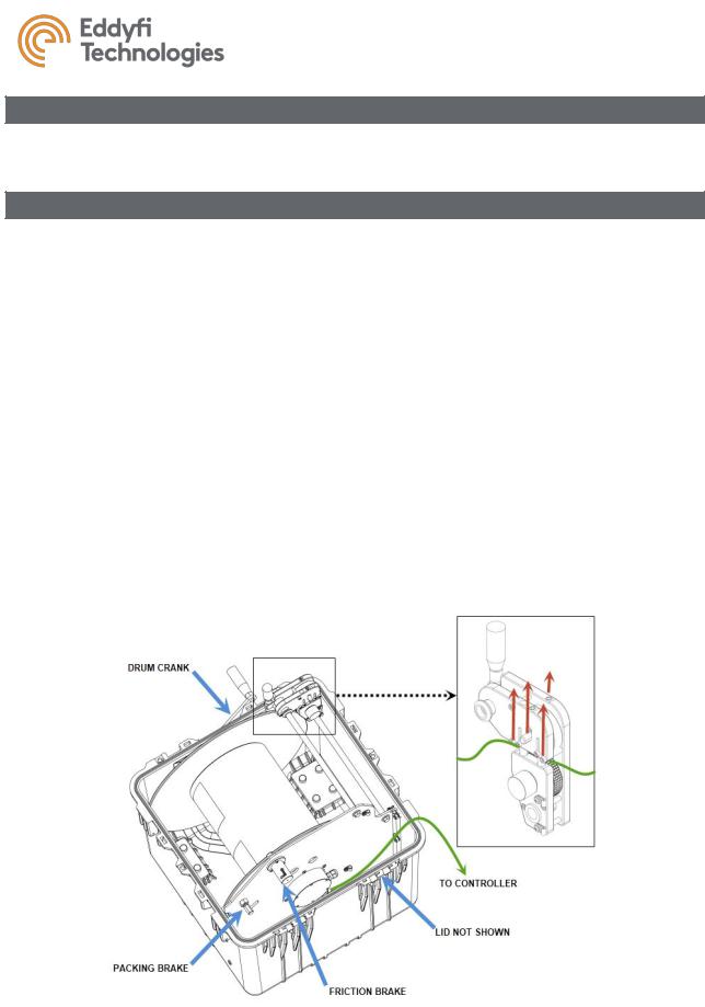
If your system includes a portable reel, follow these steps to operate:
1.Remove the shipping cap from the front of the case and insert the crank handle.
2.Connect the deck cable from the reel to the controller.
3.Disengage the packing brake (pull back and turn on the locking pin).
4.Make sure the friction brake is engaged; disengaging the friction brake can result in slack tether potentially jamming the reel.
5.Unwind some tether and connect the tether to the vehicle.
6.Run the tether through the level wind as follows:
a.There is an access slot which must be opened by lifting up the two exposed screw heads to raise the tether support shafts.
b.Pull up on both sides of the axle on the top wheel and slide the tether beneath it - failing to lift up on the wheel can scuff and damage the tether.
c.Make sure that the two wheels that sandwich the tether top and bottom in the level wind are tracking properly as the tether is paid out - this tells the controller how much tether the reel has unwound and how far your vehicle has travelled.
User Manual
Document: UMDW014058.docm |
Revision: A03 |
Created by: KW |
Date: 10 Oct 2019 |
3075415-A03 |
|
|
|
|
|
Source Location: C:\ePDM\ISLEng\products\dw-versatrax150mkii\manuals\UMDW014058.docm |
|
Page 16 of 57 |
||
|
|
|
|
|

Versatrax 150™
Tether Handling
The tether is one of the most important parts of the system. It feeds power and control signals to the system and returns data to the controller. If the tether is damaged from improper use, poor handling or an accident, the system may become inoperable. This could lead to significant downtime, loss of production, and avoidable costly repairs. It is encouraged to stress the importance of the tether and its use to anyone operating or maintaining the system. For maximum tether life and reliability, we recommend the following tether handling tips.
•Do not step on the tether
•Do not drive over the tether
•Do not bend the tether beyond its minimum bend radius
•Do not kink the tether
•Do not snap load the tether
•Avoid loading the tether whenever possible
•Always use the cable grip strain relief if applicable to your system
•Regularly inspect the tether for damage
•Regularly clean the tether
Note: Protecting the conductors inside the tether is critical to the life and operation of the tether. Proper tether handling and care will result in extended tether life and system reliability.
User Manual
Connector Handling
Connectors are an essential part of system reliability. They should be properly maintained and cared for to ensure long life and reliability. It is recommended to follow these steps to help prevent damage and increase the life of connectors.
•Always put the cap back on the tether bulkhead when the tether is disconnected
•Always inspect the end of the connector prior to engaging
•Never plug in a dirty or damaged connector
•Visually align key-ways or locating pins prior to engaging the connector
•Always fully engage or tighten the connector
•Secure locking collars finger tight
•Install dummy plugs on unused connectors
•Disconnect by pulling straight, not on an angle
•Do not pull on the cable to disengage the connector
IMPORTANT: Never “Hot Plug” any connector, this will result in internal damage to the electronics. Power down the system prior to connecting the inspection system tether.
Note: Never use WD-40 or similar solvent-based fluids on connectors or crawlers. These will cause the rubber parts of the connector or crawler to soften and swell rendering them inoperable.
Document: UMDW014058.docm |
Revision: A03 |
Created by: KW |
Date: 10 Oct 2019 |
3075415-A03 |
|
|
|
|
|
Source Location: C:\ePDM\ISLEng\products\dw-versatrax150mkii\manuals\UMDW014058.docm |
|
Page 17 of 57 |
||
|
|
|
|
|

Versatrax 150™
SubConn Connector: Lubrication and Cleaning
•Periodically apply Molykote 111 silicone grease or equivalent before mating connectors
•For dry mate connections, a layer of grease corresponding to 1/10 the socket depth should be applied to the female connector
•After greasing, fully mate the male and female connector and remove excess grease from the connector joint
•General cleaning and removal of sand or mud on a connector should be performed using a spray-based contact cleaner like isopropyl alcohol
Impulse Connector: Lubrication and Cleaning
•Lubricate mating surfaces regularly with 3M Silicone spray or equivalent, DO NOT GREASE
•Lubricate O-rings with Molykote 111 or equivalent
•Use dust caps to protect connectors wherever possible
•Clean connectors with soap and fresh water, rinse out with alcohol and allow connector to air dry before using.
User Manual
System Installation
The following describes a typical installation scenario recommended by Eddyfi Technologies.
Vehicle Layout
A typical set up for a pipe inspection system is based on a covered two ton or larger box truck. The truck carries the power source (generator) and houses the power supply and control system in a dry, covered environment. The computer / control console and recording equipment are placed in an office-like room built into the truck. The rear wall of the truck should open completely. The winch, crane and other equipment can be mounted at the back of the truck box near the door for easy deployment. The truck should also contain the maintenance space with ample bench room for maintaining, configuring, and washing down the vehicle and equipment.
The vehicle should be operated by a crew of at least two. Most importantly, a person should always be available to tend to the tether. This person may also play a role in vehicle inspection and deployment. A second person drives the vehicle, conducts the inspection and ensures a good recording.
The operations crew should be able to communicate quickly with each other to allow fast response in case of an emergency like a tether hang up. It is recommended that a signal system be set up so that the operators may work efficiently and safely as a team. It is always advantageous for both operators to be aware of full system status.
Document: UMDW014058.docm |
Revision: A03 |
Created by: KW |
Date: 10 Oct 2019 |
3075415-A03 |
|
|
|
|
|
Source Location: C:\ePDM\ISLEng\products\dw-versatrax150mkii\manuals\UMDW014058.docm |
|
Page 18 of 57 |
||
|
|
|
|
|
 Loading...