

Eddyfi technologies Lyft User Manual
Corrosion Assessment Redened
User’s
Manual

ii | www.eddy.com

Contents
General Precautions and Conventions
General Precautions x
Safety Precautions x
Conventions xi
Acronyms xii
EMC Directive Compliance xii
Calibration and Warranty Seals xii
Limited Warranty xiii
Copyrights xiii
Lyft System Overview
Introducing the Lyft System 2
Positioning Lyft 8
Removing the PECA Probe Encoder 9
Calibrating PECA Probes 9
Starting Lyft 9
Shutting Down Lyft 10
Connecting Probes 10
Batteries 10
Software Overview
Introducing the Lyft Software 14
Workow Overview
Typical Inspection Workow 28
Creating/Selecting a Project 29
Creating/Opening a Component 29
Adding/Editing a Scan Zone 30
Creating a Setup 31
Applying SmartPULSE 33
Acquiring Data 35
Recalibrating the Wall Thickness 36
Adding Indications to a Report 37
Generating a Report 38
Managing Data 38
Enabling and Disabling the Multi-Touch Display 40
Remote Control Reference 41
Lyft Pro Software
Lyft Pro 46
| iii

Preferences
Managing Preferences 50
Keypad and Keyboard Functions
Keyboard Shortcut Keys 54
Maintenance and Troubleshooting
Maintaining Lyft 56
Updating and Upgrading Software 58
Troubleshooting 60
Specications
General 62
Environmental 62
Probes 62
Performance 63
Connector Reference
PEC Connector 66
I/O Connector 66
Ethernet Connector 66
HDMI Connector 67
USB Connectors 67
Audio Jack 68
Using the Optional Harness
Adjusting the Harness 70
Setting Up the Extension Pole
Setting Up the Extension Pole 78
Using the Array Probe Straps
Adjusting the Probe Curvature 82
Lyft Software & Service Plans/Lyft Software Licensing Terms
Lyft Software and Service Plans/Lyft Software Licensing Terms 88
iv | www.eddy.com

Figures
Figure 1 PECA probe 7
Figure 2 Lyft in horizontal position 8
Figure 3 Lyft in tilted position 8
Figure 4 PECA probe encoder removal 9
Figure 5 Shutting down Lyft 10
Figure 6 Optional battery charger 11
Figure 7 Backstage view: General 14
Figure 8 Backstage view: Scan Area 15
Figure 9 Backstage view: Report Summary 16
Figure 10 Backstage view: Documentation 16
Figure 11 Backstage view: Help 17
Figure 12 Front-stage view 18
Figure 13 Pulsed eddy current array A-scan view 19
Figure 14 Information view 20
Figure 15 Home ribbon 22
Figure 16 Setup ribbon 23
Figure 17 Layout ribbon 23
Figure 18 Current A-scan view ribbon 24
Figure 19 Current information view ribbon 24
Figure 20 Current C-scan view ribbon 25
Figure 21 Analysis Ribbon 25
Figure 22 Edge Smoothing dialog box 26
Figure 23 Typical inspection workow 28
Figure 24 Open dialog box 29
Figure 25 Create Component dialog box 29
Figure 26 Open dialog box 30
Figure 27 Add Scan Zone dialog box 30
Figure 28 Probe selection 31
Figure 29 Scan denition 31
Figure 30 SmartPULSE dialog box 33
Figure 31 PEC Autoset dialog box 33
Figure 32 Wall Thickness Calibration dialog box 34
Figure 33 Repeatability Optimization dialog box 34
Figure 34 Wall Thickness Calibration dialog box 36
Figure 35 Placing cursor over target defect 37
Figure 36 Add indication dialog box 37
| v

Figure 37 Indication added 37
Figure 38 Generate Report dialog box 38
Figure 39 Component Transfer dialog box 39
Figure 40 Project Transfer dialog box 39
Figure 41 Help section 40
Figure 42 Setup tab 41
Figure 43 External Path Selection dialog box 46
Figure 44 Scan Area section 47
Figure 45 Calibration Propagation dialog box 47
Figure 46 Selecting an output in a C-scan 48
Figure 47 CWT% C-scan 48
Figure 48 System preferences 50
Figure 49 Selecting a logo 50
Figure 50 System preferences 51
Figure 51 Wi-Fi Networks dialog box 51
Figure 52 Display preferences 52
Figure 53 Keyboard Shortcuts dialog box 54
Figure 54 Encoder and replacement clamp ring 56
Figure 55 Pliers in expanding conguration 57
Figure 56 Clamp ring sitting on plier 57
Figure 57 Clamp ring installation 57
Figure 58 Clip-on encoder protective cap 58
Figure 59 Update dialog box 58
Figure 60 Options menu 59
Figure 61 System recovery interface 59
Figure 62 Slipping the harness on 70
Figure 63 Adjusting the shoulder straps 71
Figure 64 Adjusting the belt’s height 71
Figure 65 Securing the chest straps 71
Figure 66 Securing the belt 72
vi | www.eddy.com
Figure 67 Shoulder anchor straps 72
Figure 68 Unfastening the straps 73
Figure 69 Sliding strap loop through bumper hook 73
Figure 70 Securing anchor strap 73
Figure 71 Alternative method of securing anchor strap to bumper 74
Figure 72 Anchor strap on harness belt 74
Figure 73 Slipping male buckle through bumper 74
Figure 74 Mating battery compartment side anchor strap 75

Figure 75 Closing battery compartment door. 75
Figure 76 Mating shoulder anchor strap 75
Figure 77 Tightening shoulder anchor straps 76
Figure 78 Belt-slinging probe cable 76
Figure 79 PEC probe supports and screws 78
Figure 80 Securing supports to PEC probe 78
Figure 81 Sliding PEC probe on extension pole head 79
Figure 82 Securing PEC probe to extension pole head 79
Figure 83 Running PEC probe cable through pole hoops 79
Figure 84 Connecting PEC probe connector to extension pole remote control 80
Figure 85 Locked latches 82
Figure 86 Unlocked latches 82
Figure 87 Probe on a pipe with curvature locked 83
Figure 88 Carriage installed on straps 83
Figure 89 Handle installed on element 6 84
Figure 90 Installed erasable marker 84
Figure 91 Grid-As-U-Go the PECA probe 85
Figure 92 Installed Grid-A-U-Go 85
| vii

Tables
Table 1 Lyft single-element probe status LEDs 6
Table 2 PECA probe status LEDs 7
Table 3 Multi-touch behavior in C-scan view 21
Table 4 Analysis mode remote control reference 41
Table 5 Grid mapping data acquisition remote control reference 41
Table 6 Dynamic mode data acquisition remote control reference 42
Table 7 SmartPULSE remote control reference 42
Table 8 Survey mode remote control reference 42
Table 9 PEC Autoset remote control reference 42
Table 10 Wall thickness calibration remote control reference 43
Table 11 Repeatability optimization remote control reference 43
Table 12 Keyboard shortcut 54
Table 13 General specications 62
Table 14 Environmental specications 62
Table 15 Single-element probe specications 62
Table 16 Array probe specications 63
Table 17 Performance 63
Table 18 I/O connector data 66
Table 19 I/O connector pinout 66
Table 20 Ethernet connector data 66
Table 21 Ethernet connector pinout 66
Table 22 HDMI connector data 67
Table 23 HDMI connector pinout 67
Table 24 USB connector data 67
Table 25 USB connector pinout 67
Table 26 Audio jack data 68
Table 27 Audio jack pinout 68
viii | www.eddy.com

General Precautions and Conventions
General Precautions and
Conventions
| ix

General Precautions and Conventions
General Precautions
The following safety precautions are to be observed at all times when using Lyft®. Make sure that you
review them before turning on the system.
• Keep this document in a safe place for future reference.
• Carefully follow the installation and operation procedures detailed herein.
• Respect the safety warnings on the instrument and in this document.
• Lyft should only be used by qualied personnel.
• When transporting Lyft, it is your responsibility to make sure that you apply the safety precautions
dictated by the relevant local governing bodies.
• Always connect the power supply to a properly grounded receptacle, extension cord, or power
bar. Grounding a single conductor of a two-conductor outlet is not sufcient protection for Lyft.
• Only connect the system to a power source corresponding to the type indicated on the rating plate.
• If you use the system in a manner that deviates from that specied by Eddy, the protection
provided on the equipment may be rendered null and void.
• Do not use substitute parts or perform unauthorized modications to the system.
• Service instructions, when applicable, are intended for trained service personnel only.
• Always make sure that the system is unplugged from any power supply before servicing.
• To avoid dangerous electric shock, do not perform any service on the system unless qualied to do
so. If you encounter any problems or have questions regarding this system, contact Eddy or an
authorized Eddy representative.
Safety Precautions
Observe the following safety precautions scrupulously when using Lyft.
Rear Stand
Because Lyft is a portable system, it is designed to be used under tough conditions. It is, however, not
indestructible. To avoid damaging Lyft, use its rear stand when operating Lyft in a tilted position. Do not
use Lyft in the upright position, as it may topple over or fall off the work surface.
x | www.eddy.com
General Precautions and Conventions
Conventions
Typographical
The following typographical conventions are used throughout this document:
Italic
Used for le names and paths.
Bold
Used to indicate menu items, named user interfaces, and place emphasis on specic words or phrases.
Items in bold type are capitalized to reect the actual interface.
SMALL CAPITALS
Used to indicate instrument interface indications.
Marking and Symbols
The following symbols ap p e ar on t he instr u m e nt a nd p e rt a i n to safet y re g u l ations that shou l d be care fully
observed:
This label is used as a general warning sign. It indicates that you should refer to this user’s
guide to obtain the necessary information for proper protection of the instrument and its
users.
This label is used to indicate high voltage. It draws your attention to the presence of
hazardous voltages (within the product enclosure or accessible externally) that may
constitute a risk of electric shock to persons. Always refer to the user’s guide to ensure
proper protection and safety.
The RoHS compliance logo signies that this product complies with the Restriction of
Hazardous Substances directive 2002/95/EC. This directive restricts the use of lead,
mercury, cadmium, hexavalent chromium, polybrominated biphenyl, and polybrominated
diphenyl ether in certain classes of electrical and electronic units as of July 1, 2006.
This label acts as a reminder that you should dispose of this system in accordance with your
local Waste Electrical and Electronic Equipment (WEEE) regulations. This system was
manufactured to the high quality standards of Eddy to ensure safe and reliable operation
when it is used as stated in this document. Due to its nature, this instrument may contain
small quantities of substances known to be hazardous to the environment and to human
health if released in the environment. As such, systems falling under WEEE regulations
should not be disposed of in the public waste stream.
| xi

General Precautions and Conventions
Safety Indications in This Document
The safety indications in this document are intended to ensure your safety and the integrity of the
system.
Warning
The warning indication calls your attention to a procedure or a practice (or the like) that, if performed
incorrectly, can result in injury. Do not ignore warning indications — make sure that you understand the
condition before proceeding.
Caution
The caution indication calls your attention to a procedure or practice (or the like) that, if performed
incorrectly, can result in material damage, loss of data, or both. Do not ignore caution indications —
make sure that you understand the condition before proceeding.
Important
Calls attention to information important to completing tasks.
Note
Calls attention to an operating procedure, a practice, or the like that requires special attention. Notes
also indicate useful related, but parenthetical information that is unessential.
Acronyms
PEC: Pulsed eddy current
PECA: Pulsed eddy current array
CWT: Compensated wall thickness
EMC Directive Compliance
FCC Compliance (USA)
This equipment was tested and found to comply with the limits for a Class A digital device, pursuant
Part 15 of the FCC Rules. These limits are designed to provide reasonable protection against harmful
interference when the equipment is operated in a commercial environment. This equipment generates,
uses, and can radiate radio frequency energy and, if not installed and used in accordance with the user’s
guide, may cause harmful interference to radio communications. Operation of this equipment in a
residential area is likely to cause harmful interference in which case you will be required to correct the
interference at your own expense.
ICES Compliance (Canada)
This ISM device complies with Canadian ICES-001.
Cet appareil ISM est conforme à la norme NMB-001 du Canada.
AS/NZS Compliance (Australia/New Zealand)
This device complies with Australia and New Zealand AS/NZS 4252.2 (IEC 61000-6-4) and AS/NZS
61000-6-2 (IEC 61000-6-2).
Calibration and Warranty Seals
The calibration seal is at the back of the instrument. Lyft is also equipped with a warranty seal.
Important
Broken seals void the calibration certication and product warranty.
xii | www.eddy.com

General Precautions and Conventions
Limited Warranty
Eddy NDT, Inc. warrants the hardware to be free of any defects in materials or workmanship for a
period of twelve (12) months from the date of delivery, under normal use and service. These warranties
are limited to the original purchase of the product and are not transferable.
Eddy NDT, Inc. will repair or replace any product component or documentation, at its option and at
no additional charge, if found defective within the warranty period. The purchaser is responsible for
returning the product to Eddy NDT, Inc.
Eddy NDT, Inc., will not be held responsible in any way whatsoever for damage resulting from improper
installation, accident, misuse, or from service or modication of the product by anyone other than Eddy
NDT, Inc., or an authorized Eddy NDT, Inc. service center.
Eddy NDT, In c . wil l no t b e h eld res p onsi b l e i n a ny w ay what soever for di r e ct , indire c t , s peci a l, inc i d ent al,
or consequential damages resulting from possession, use, improper installation, accident, service,
modication, or malfunction of the product (including, without limitation, damages for loss of business
prots, business interruption, loss of business information, or other pecuniary loss). Eddy’s total shall
in no event exceed the purchase price of the applicable item(s).
This warranty is in lieu of all other warranties, whether oral, written, expressed, or implied, including
any warranty of merchantability or tness for a particular purpose, and no other representation or
claims of any nature shall be binding on or obligate Eddy NDT, Inc.
This agreement is governed by the laws of the province of Québec, Canada. Each of the parties hereto
irrevocably attorns to the jurisdiction of the courts of the province of Québec and further agrees to
commence any litigation which may arise hereunder in the courts located in the judicial district of
Québec.
Copyrights
This document and the product and programs it describes are protected by the Copyright Act of Canada,
by laws of other countries, and by international treaties, therefore may not be reproduced, in whole or
in part, whether for sale or not, without prior written consent from Eddy NDT, Inc. Under copyright
law, copying includes translation in other languages and formats.
© Eddy NDT, Inc., 2018
This document was prepared with particular attention to usage to ensure the accuracy of the information
it contains. It corresponds to the version of the product manufactured prior to the date appearing on
the back cover. There may, however, be some differences between this document and the product, if
the product was modied after publication.
The information contained in this document is subject to change without notice.
| xiii

General Precautions and Conventions
xiv | www.eddy.com

Chapter 1
Lyft System Overview
Lyft System Overview
| 1
Lyft System Overview
Introducing the Lyft System
Thank you for purchasing the Eddy® Lyft® system. This chapter offers an overview of the system, its
components, and probes.
What is in the Box
Lyft comes with the following standard accessories:
• Two, high-capacity batteries
• One power adapter (100–240 V)
• Power cords (one for North America, one for Europe)
• User documentation
• Stylus
• Transport case
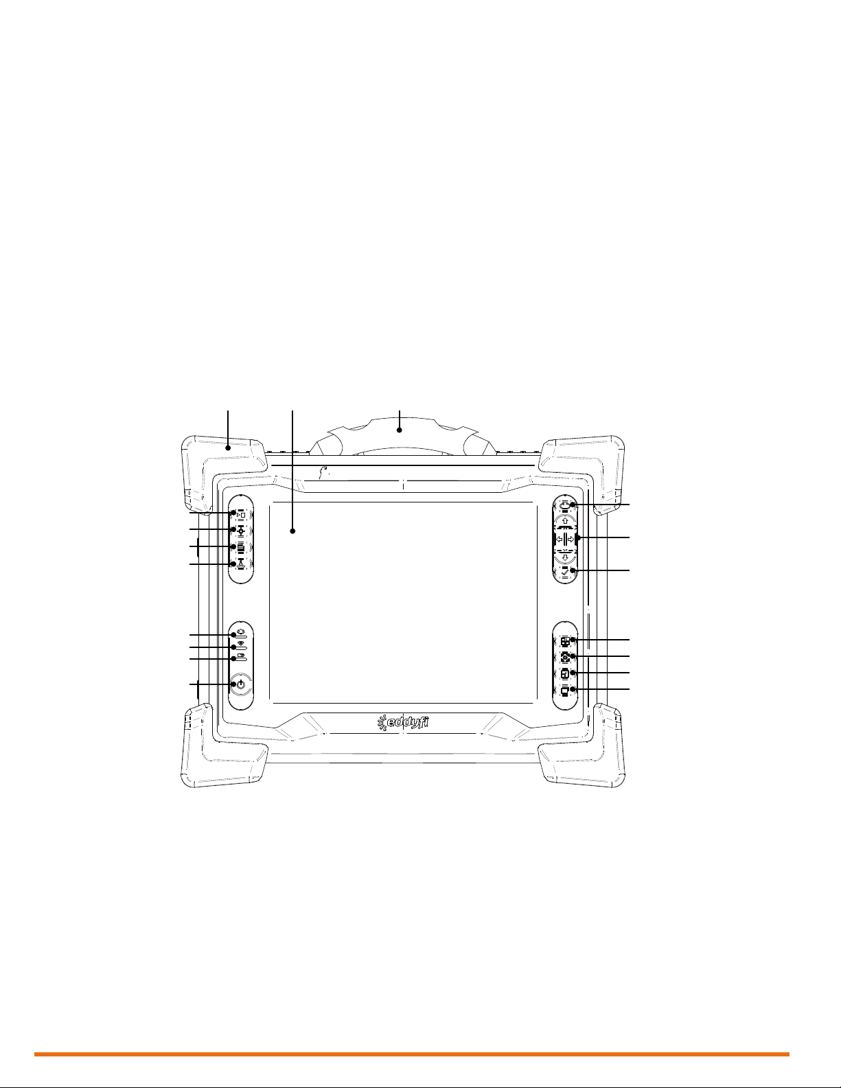
Instrument Overview
Front
10 119
8
7
6
5
4
3
2
1
12
13
14
15
16
17
18
1. Power button
2. Battery indicator
2 | www.eddy.com
Use to turn the instrument on and off. The
power indicator at the center of the button
behaves as follows:
• Green: Lyft is on
• Blin k ing yell o w /or a nge: Ly f t is on st andby
• Unlit: Lyft is off
Displays the state of the batteries when the
instrument is on. Depending on the power
mod e ( DC or bat t er y), th e ind i ca t or be hav e s
differently:
DC power
• Green: batteries fully charged
• Blinking green: batteries charging
• Red: battery or charger error
• Unlit: no batteries
Battery power
• Unlit: remaining charge over 40 %
• Orange: remaining charge 20–40 %
• Blinking yellow: remaining charge less
than 20 %
• Red: battery error

Lyft System Overview
3. Wi-Fi indicator
Displays the Wi-Fi status. When the
indicator is lit, the Wi-Fi is enabled. When
it is off, the Wi-Fi is disabled.
4. Alarm indicator
Used to display user- programmed errors.
The indicator remains unlit until it detects a
predened error condition, at which time it
lights red.
5. Wall thickness calibration button
Use to perform a wall thickness calibration
on the nominal thickness. A short press
calibrates on a new point, while a long press
calibrates on the data at the cursor’s
location.
6. Index button
Use to increment the index line during data
acquisition.
7. Get point button
Only use during data acquisition in gridmapping mode. It allows performing a
measurement at the cursor coordinates.
8. Start/Stop acquisition button
Use to start or stop data acquisition.
11. Handle
Use this handle to carry Lyft.
12. Keypad arrow mode selection/Disable
touchscreen button
Press to select the operation mode of the
keypad arrows (see 13). Long press this
button to enable or disable the touchscreen
(depending on its state). Follow the
instructions on the screen to complete the
operation.
13. Keypad arrows
Use these arrows to navigate the Lyft
software interface according to the selected
mode.
14. Enter button
Unused at this time.
15. Change active view button
Press to activate a different view than the
one currently active.
16. Data display button
When PECA probes are connected to the
instrument: used to activate probe guides in
C-scans. Unused with single-element
probes.
9. Heavy-duty bumpers
The four corner bumpers provide shock
absorption and support Lyft at an angle
when it is set on a at surface. The bumpers
are also hooked for harnessing. For details
about harnessing, see page 70.
10. Multi-touch display
10.4”, non-reective, backlit, high-resolution
display.
17. Maximize/Minimize view button
Use to maximize or minimize the active
view.
18. Change layout button
Use to change the Lyft software layout to
another predened one.
| 3
Lyft System Overview
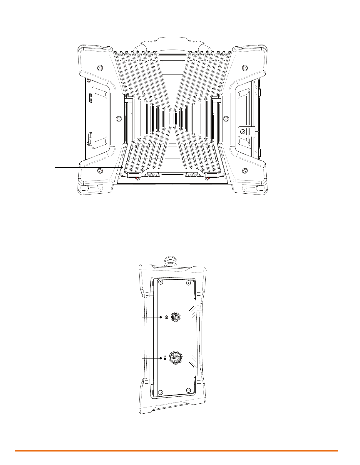
Rear
1
1. Instrument stand
The stand retracts outward to hold Lyft at
an angle, preventing the instrument from
tilting over horizontally.
Right
1
2
1. I/O connector
4 | www.eddy.com
Used to communicate with the probe’s
encoder, for example.
2. PEC connector
Con n e ct yo u r P EC pro b es to this co n nec tor.
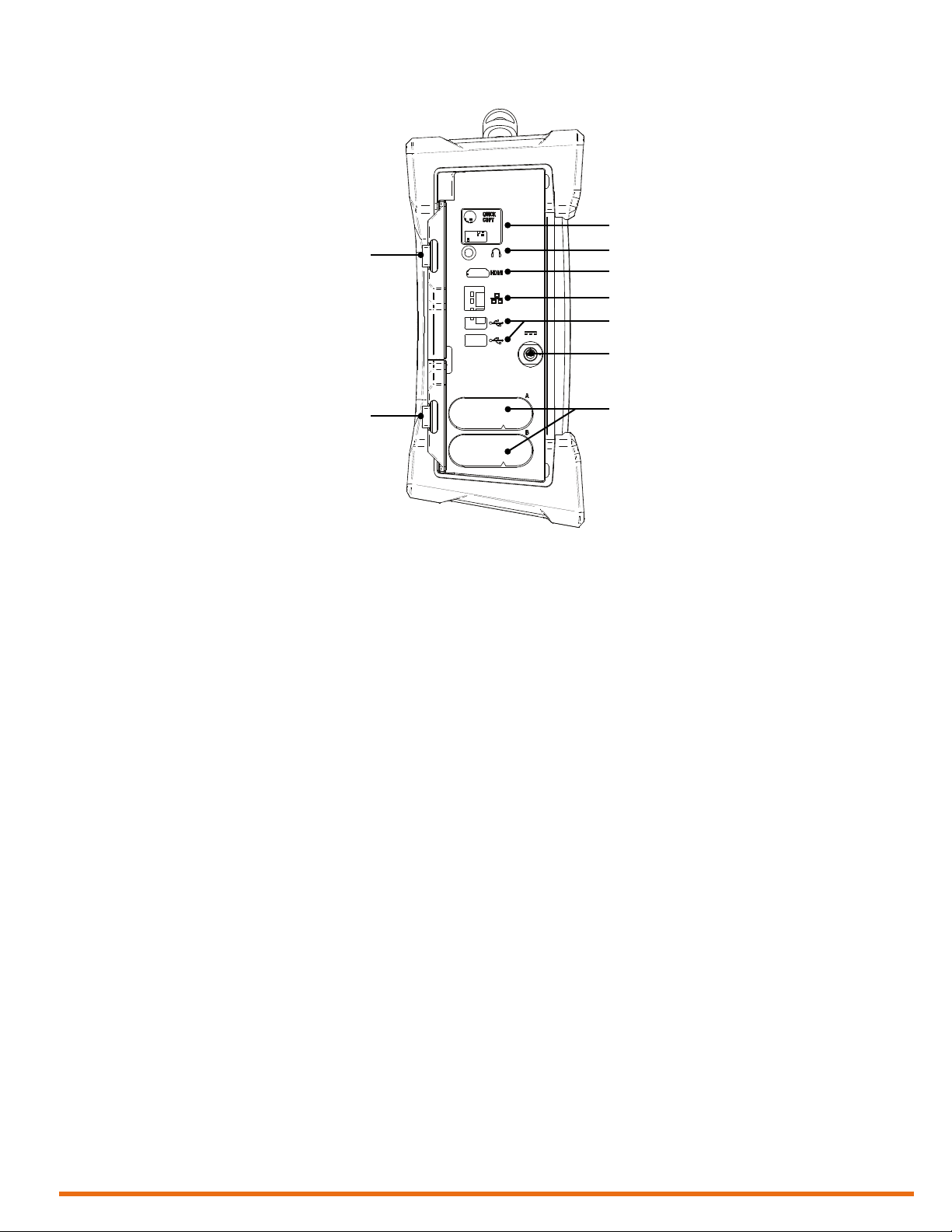
Left
Lyft System Overview
2
1
3
4
5
6
7
9
1. Protective connector door
Protects the Lyft connectors from the
elements when they are unused.
2. Quick Copy
Use to transfer all your inspection data to a
USB mass storage device.
3. Audio connector
Use to plug a headset to Lyft.
4. HDMI® connector
Use to connect an external monit or to Ly f t.
5. Network connector
Use to connect Lyft to a local area network
(LAN). The connector is equipped with two
indicators with the following behaviors:
Connection indicator (upper)
8
Connection speed indicator (lower)
• Amber : op e r ating as a gig a b i t co n n e ction
(1 G b p s)
• Green: operating as a 100 Mbps
connection
• Off: operating as a 10 Mbps connection
6. USB 2.0 connectors
Use to connect USB devices to Lyft such as
a mouse or an external disk drive.
7. Power connector
Use the supplied power cord to operate
Lyft and recharge its batteries.
8. Battery compartments
Insert the supplied batteries into the
compartments. For details about batteries,
see Batteries on page 10.
• Green: communication established with
the network
• Blinking green: activity between Lyft and
the network
• Unlit: no link to the network
9. Protective battery compartment
door
Protects the battery compartments from
the elements.
| 5
Lyft System Overview
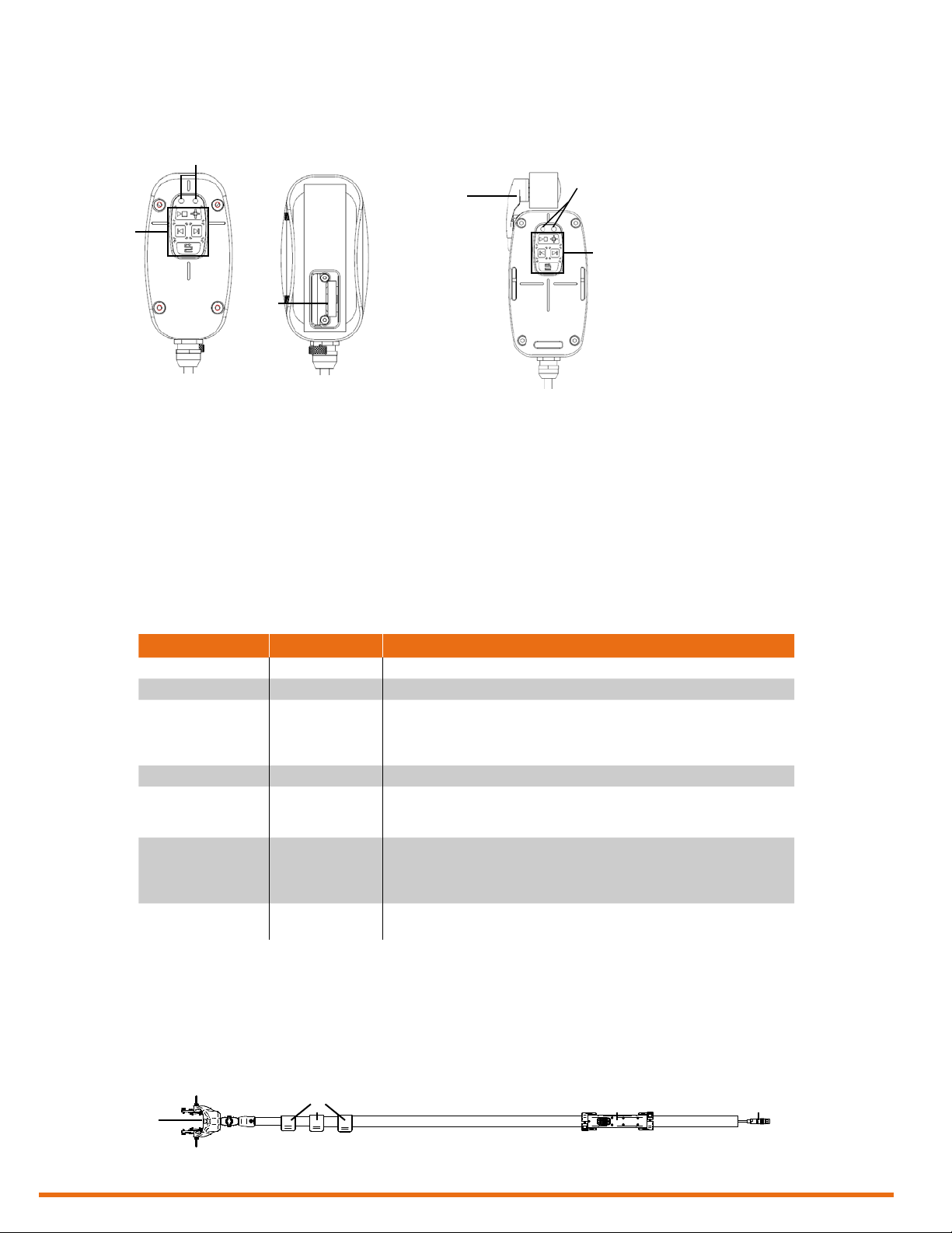
Single-Element Probe Overview
Lyft single-element probes come in three sizes: small, medium, and large. They feature the following
components.
2
First-generation probes Second-generation probes
1. Status LEDs
2. Remote controls
Table 1 Lyft single-element probe status LEDs
1
3
The green LED on the left and the red LED
on the right convey information to users, as
outlined below.
Used to perform a variety of operations
without handling the instrument. See page
41.
4
3. Built-in encoder
First-generation probes are equipped with a
high- precision, 20.53 counts/mm encoder.
4. Clip-on encoder
Second-generation probes are equipped
with high-precision, 16.04 counts/mm
encoder.
1
2
Green Red Status
Off Off Probe unconnected or unable to receive data.
1 Hz blinking (slow) Off Analysis mode: Probe detected and waiting for action.
10 Hz blinking (normal) Off Acquisition mode: Data is being acquired.
20 Hz blinking (fast) Off Dynamic acquisition mode: The probe’s position is outside the scan zone.
20 Hz blinking (fast) 20 Hz blinking (fast) PEC Autoset: Routine failed or was canceled.
On Off Grid mapping acquisition mode: Probe ready to perform acquisition.
Off On Dynamic acquisition mode: Probe moving too quickly on sample.
PEC Autoset: Routine is running.
Wall thickness calibration: Routine is running.
Repeatability optimization: Routine is running.
Wall thickness calibration: Routine failed or was canceled.
Repeatability optimization: Routine failed or was canceled.
PEC Autoset: Probe ready to perform routine.
Wall thickness calibration: Probe ready to perform routine.
Repeatability optimization: Probe ready to perform routine.
Other circumstances: Error occurred during requested operation.
Single-Element Probe Accessories
For details about these accessories, refer to the PEC probe catalog.
Single-Element Extension Pole Overview
For details about how to install a single-element or splash zone probe on the extension pole, see Setting
Up the Extension Pole on page 78.
1
2 3 4
1. Probe holder
2. Extension rings
6 | www.eddy.com
3. Remote control (see above)
4. PEC connector
Lyft System Overview
Encoder Element 1 Element 2 Element 3 Element 4 Element 5 Element 6
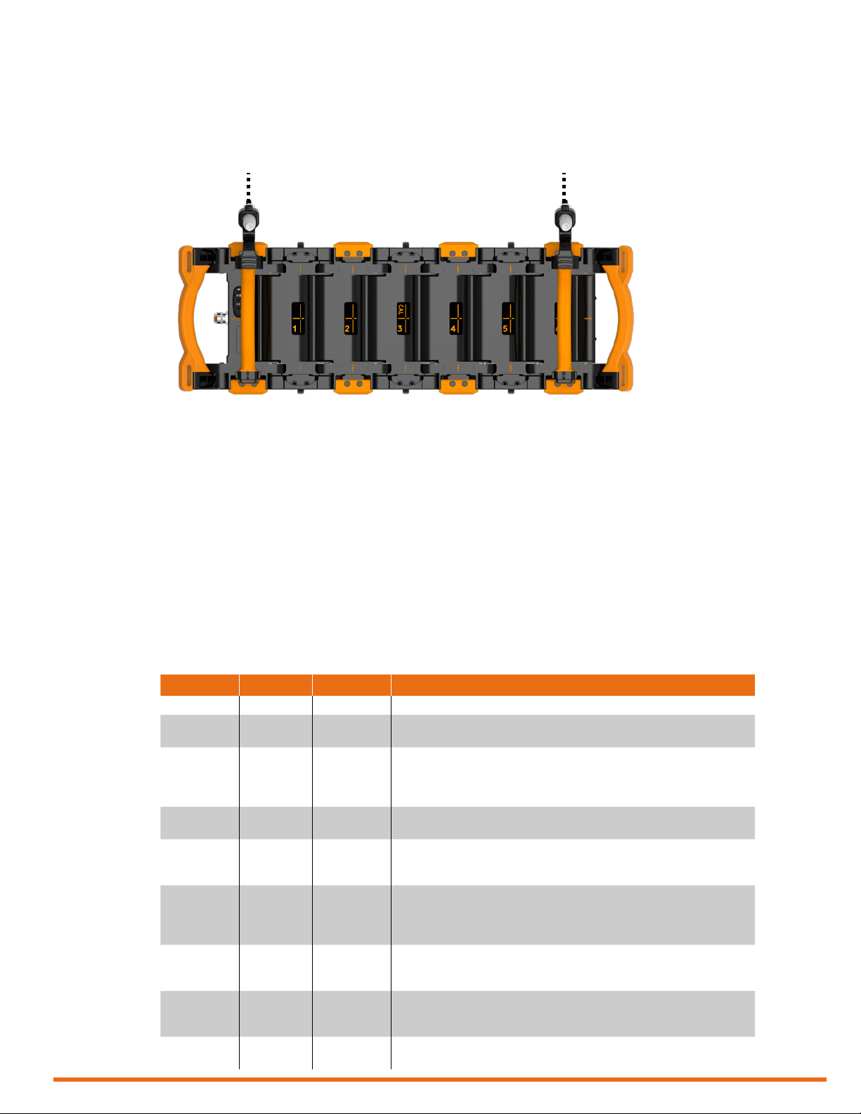
PECA Probe Overview
The PECA-6CH-MED-XXX-GA and PECA-6CH-MED-XXX-GDA 6-element PECA probes are capable
of a single-pass coverage of 457 mm (18 in) in grid or high-resolution, dynamic mode.
Figure 1 PECA probe
PECA probes roll on wheels that lift them off 12.7 mm (0.5 in) to ease inspection on insulated pipes with
straps and buckles securing the insulation. Do not add this additional liftoff to the insulation thickness
when calculating your probe’s footprint or smallest detectable defect. You can remove the wheels to
use the probe in restricted-access situations.
PECA probes are also designed to wrap around curved surfaces like pipes. Once curved, lock the shape
by pressing the locking handles toward the probe’s body. You will get the best sizing results when all the
probe elements are curved by the same amount, forming a circular arc. Positioning marks are visible on
the probe to validate the relative curvature of all array elements. To see how to lock and unlock the
probe body, see appendix D.
The probes are equipped with the same buttons as single-element probes. The red, green, and blue LEDs
indicate the operational status of the probes.
Table 2 PECA probe status LEDs
Green Red Blue Status
Off Off – Probe unconnected or unable to receive data.
1 Hz blinking
(slow)
10 Hz blinking
(normal)
20 Hz blinking
(fast)
20 Hz blinking
(fast)
On Off – Grid mapping acquisition mode: Probe ready to acquire.
Off On – Dynamic acquisition mode: Encoder is moving. Blue LED is off if red LED
– – On Dynamic acquisition mode: Typically used to conrm that the encoder is
– – Off Dynamic acquisition mode: Encoder is stopped.
Off – Analysis mode: Probe detected and waiting.
Off – Acquisition mode: Data being acquired.
Off – Dynamic acquisition mode: The probe’s position is outside the scan zone.
20 Hz blinking
(fast)
20 Hz blinking
(fast)
PEC Autoset: Routine running.
Wall thickness calibration: Routine running.
Repeatability optimization: Routine running.
PEC Autoset: Routine failed or canceled.
Wall thickness calibration: Routine failed or canceled.
Repeatability optimization: Routine failed or canceled.
PEC Autoset: Probe ready to perform routine.
Wall thickness calibration: Probe ready to perform routine.
Repeatability optimization: Probe ready to perform routine.
is active.
Other circumstances: Error occurred during requested operation.
in contact with the component.
Other circumstances: Unused.
Other circumstances: Unused.
| 7

Lyft System Overview
PECA Probe Accessories
For details about PECA probes accessories, refer to the PEC probe catalog. To learn how to install the
probe on a pipe using accessory straps and carriages, see Appendix D on page 81.
Application-Specific Probes and Accessories
For details about the splash zone, underwater, galvanized-steel, and tank oor probes, as well as cables
and other PEC accessories, refer to the PEC probe catalog.
Positioning Lyft
Lyft must be properly positioned prior to use so that you do not run the risk of dropping the instrument
or the instrument falling over. Lyft has two safe operating positions: horizontal and tilted. To use there
a tilted position, simply pull out the stand located at the rear of the instrument until Lyft is at the desired
angle. If you are using Lyft with the optional harness, see Adjusting the Harness on page 70 for details.
Figure 2 Lyft in horizontal position
Figure 3 Lyft in tilted position
Caution
It is possible to use Lyft while it rests on its lower bumpers, but this is not a safe operational position
as the instrument may fall over. If you want to use Lyft at an angle, use the stand located at the rear of
the instrument.
Important
Regardless of how you position the instrument, you must always have a minimum clearance of 10 cm
(4 in) on all sides of the instrument. Always position the instrument away from heat sources. This ensures
proper heat dissipation while the instrument is in use.
8 | www.eddy.com
Lyft System Overview
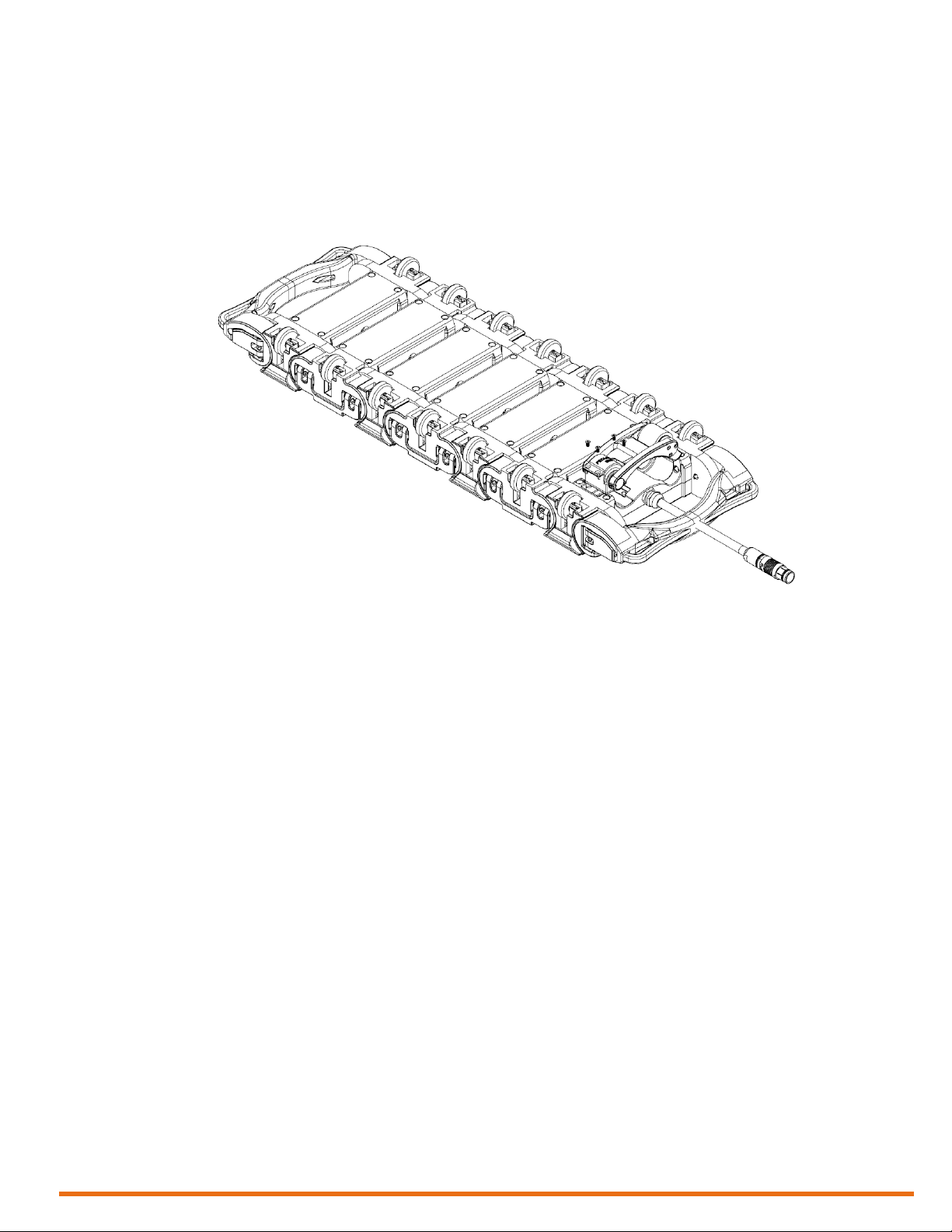
Removing the PECA Probe Encoder
The GDA probe is equipped with a detachable encoder. The encoder can be retracted when it is not
used. To remove the encoder, place the probe on a secure surface and unscrew the four screws visible
at the base of the encoder arm when the probe is upside down.
Figure 4 PECA probe encoder removal
Calibrating PECA Probes
The probe is calibrated using the element 3 (marked CAL) as a reference. Refer to the PECA training
material for details.
Starting Lyft
Proceed as follows to turn on your instrument or exit the standby mode:
1. Make sure that at least one of the two batteries is inserted into battery compartment A of the
instrument or that the instrument is plugged to an external power source using the supplied power
cord.
2. Press the power button.
The power indicator at the center of the power button lights green.
| 9

Lyft System Overview
Shutting Down Lyft
Proceed as follows to shut down your instrument:
1. Save all your data.
2. Press the power button.
Figure 5 Shutting down Lyft
3. Tap the button of your choice.
Connecting Probes
Four options are available.
The instrument shuts down.
Connecting a PEC Probe
Eddy PEC probes come in three models: small, medium, and large. These probes hook up to Lyft’s PEC
connector. Proceed as follows to do so:
1. If you have not already done so, remove Lyft from its carrying case and place it on your working
surface as outlined in Table 2 on page 7.
2. If you have not already done so, remove the protective caps from the PEC and I/O connectors.
3. Align the probe’s 27-pin male connector with the PEC connector on the instrument.
Hint
The alignment mark on the connector should be facing you when you face the instrument.
4. Push the connector until you hear it click.
5. Align the probe’s 12-pin male encoder connector with the I/O connector on the instrument.
Hint
The alignment mark on the connector should be facing you when you face the instrument.
6. Push the connector until you hear it click.
Batteries
Lyft can be used under battery power. The instrument is designed with two battery cradles under the
protective battery compartment door, but can be powered by a single battery. Lyft uses Li204SX-7800
lithium-ion rechargeable batteries from Emerging Power, which do not suffer from the memory effect
affecting previous generations of batteries.
Warning
Whenever carrying Lyft in its transport case, remove the batteries from the instrument and make sure
that they cannot come in contact during transport, as this poses a signicant re and explosion hazard.
When carrying Lyft, it is the user’s responsibility to make sure that the safety precautions used are in
accordance with the local department of transportation (or equivalent governing body) rules and
regulations.
Lyft’s transport case comes with two slots, tted to receive the batteries when removed from the
instrument.
10 | www.eddy.com

Lyft System Overview
Note
Make sure that you do not replace the batteries by batteries other than Li204X-7800 lithium-ion
rechargeable batteries from Emerging Power. Contact your Eddy representative for more information
about pricing and availability or replacement batteries.
Inserting/Removing Batteries
Inserting Batteries
1. On Lyft’s left side, unlatch the battery compartment’s door, and then open it.
2. Align your battery with one of the battery cradles.
Note
Battery cradles are marked A and B. If you are inserting only one battery, it does not matter which
of the two cradles you use.
3. Make sure that the battery contacts are facing inward and upward.
4. Slide the battery into the battery cradle until it is fully inserted. You should feel the battery contacts
snap into place.
Removing Batteries
1. On the left side of Lyft, unlatch the battery compartment’s door, and then open it.
2. Grab the battery tab between thumb and forenger.
3. Pull on the tab.
You will feel the battery contacts being released.
4. Slide the battery out of its cradle.
Hot Swapping Batteries
You can remove one of the Lyft batteries when the instrument is turned on as Lyft can operate with a
single battery. Should the power in the remaining battery be insufcient to keep Lyft operating, the
instrument shuts down without damaging electronic components, but all your work in progress in the
Lyft software (acquisition, etc.) is lost.
Charging Batteries
Note
Batteries do not recharge when their internal temperature exceeds 45 °C (113 °F). Batteries also do not
power Lyft when the instrument’s internal temperature exceeds 55 °C (131 °F).
Using the Optional Battery Charger
An optional battery charger is available from Eddy. Contact your Eddy representative for more
information about pricing and availability. This charger conditions and calibrates the instrument’s
batteries, which is important to maximize their lives. We recommend calibrating the batteries every six
months.
Figure 6 Optional battery charger
Status window
Calibration buttons
Battery slots
| 11

Lyft System Overview
To charge the batteries with the optional charger:
1. Place the charger on a at and level surface, away from heat and moisture sources.
2. Insert the power supply’s DC connector into the back of the external charger.
3. Connect the power supply to an AC supply using the supplied cable. All the LEDs ash momentarily
4. Insert the batteries into the battery slots while making sure that the contacts are fully seated.
Calibrating Batteries
To ensure that your batteries perform at their full capacity for the longest possible time, it is important
to calibrate them on a regular basis. Calibration involves a standard battery charge followed by a deep
discharge, and then a complete charge. This procedure usually takes 10 to 13 hours, whereas a standard
charge only takes approximately 3.5 hours.
Calibrate batteries by placing them in the optional charger and then pressing the calibration button. We
recommend calibrating your batteries at least every six months.
to let you know that power is present.
The charger automatically begins charging the batteries and the LEDs in the status window display
the following information:
• Blinking green: battery charging
• Green: battery fully charged
• Blinking blue: battery calibrating
• Blue: battery charge gauge calibrated
• Blinking red: battery charge gauge in need of calibration
• Red: error
Storing Batteries
Whenever transporting Lyft in its case, remove the batteries from the instrument, place them in plastic
bags, and then make sure that they cannot come in contact during transport, as this is a signicant re
and explosion hazard. Lyft’s transport case is outtted with two slots intended for the batteries. We
recommend that you take advantage of them.
12 | www.eddy.com

Chapter 2
Software Overview
Software Overview
| 13
Software Overview
Introducing the Lyft Software
The software running on Lyft is a powerful and easy-to-use acquisition and analysis software. It is
specically designed for pulsed eddy current inspections and relies on intuitive wizards to congure
setups.
The software benets from a graphical user interface (GUI) designed to simplify the inspection process
and enhance your experience. The multi-touch display is the best way of interacting with Lyft, but you
can also use a USB mouse and keyboard, if necessary.
Through the GUI, all the functions associated to inspection project management, the global settings, and
the preferences are in what is referred to as the backstage view. All inspection work, calibration,
acquisition, and analysis is in what is referred to as the front-stage view. This is how the software offers
a streamlined and coherent interface that makes the learning process easy.
Backstage Overview
The backstage view is composed of ve sections.
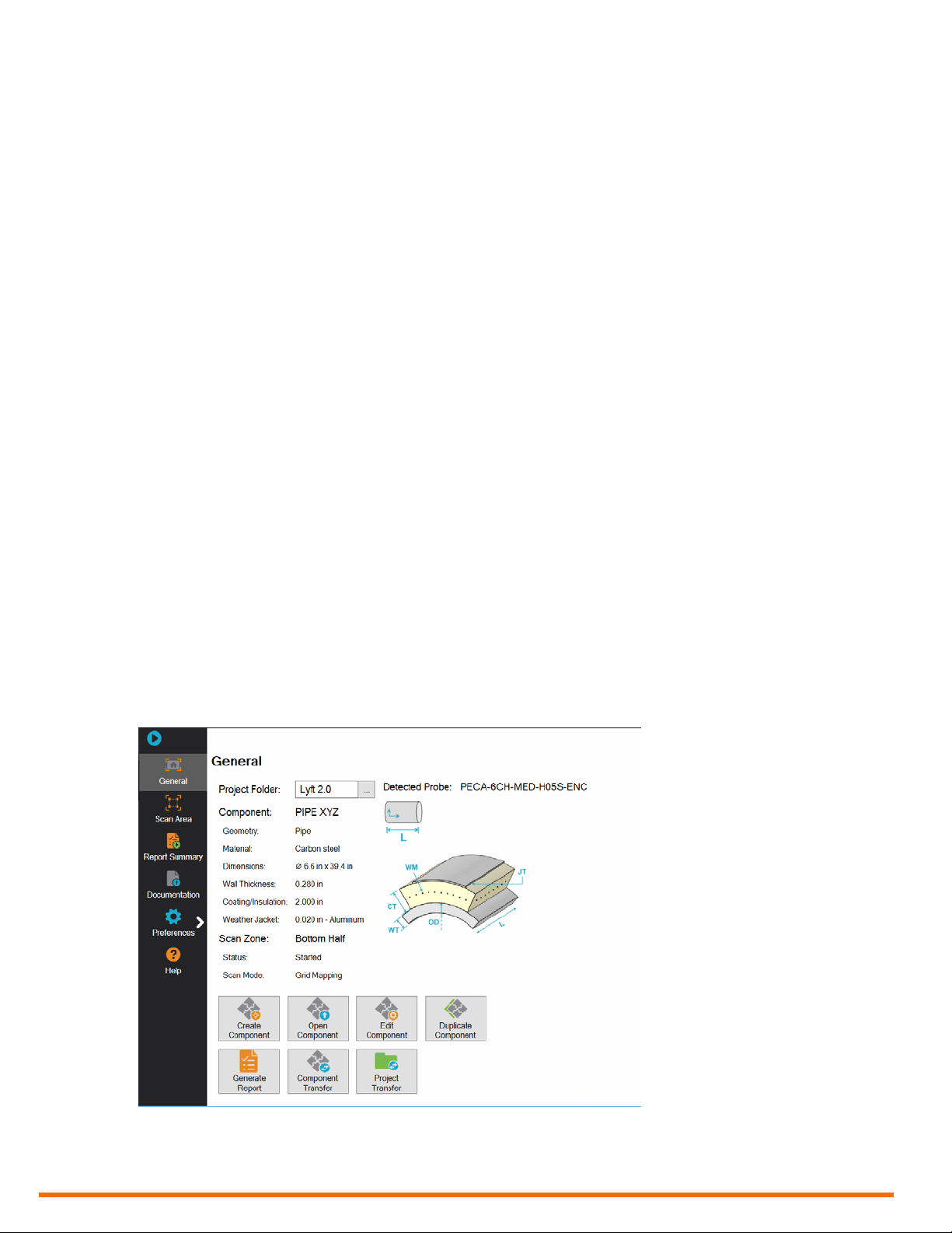
General Section
The default section and rst section of the backstage view is the General section, which contains
information about:
• Probe currently connected to Lyft
• Component description (pipe, insulation, jacket)
• Current scan zone
This is where you:
• Select project folders
• Create, open, edit, or duplicate components
• Transfer components and projects
• Generate reports
Figure 7 Backstage view: General
14 | www.eddy.com
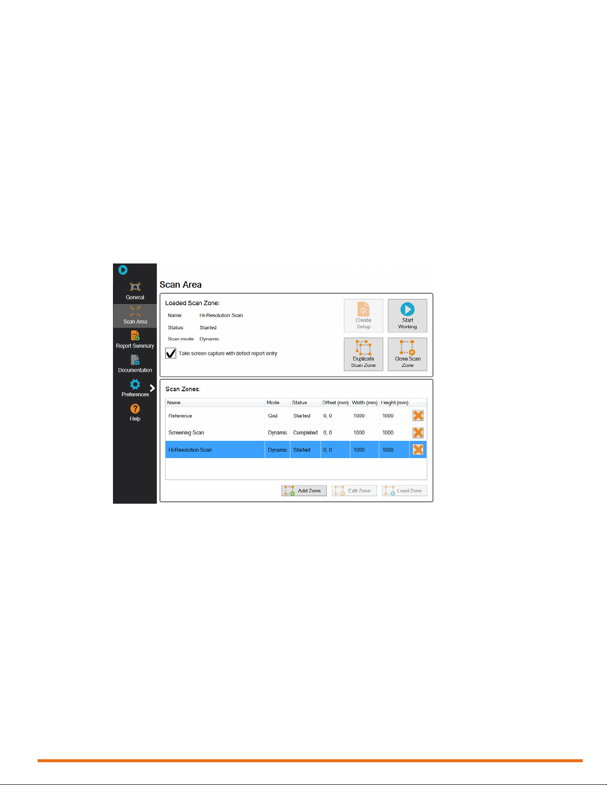
Scan Area Section
This section of the backstage contains information about the loaded scan zone and all the scan zones of
the component. This is where you (upper portion of the view):
• Create setups
• Start inspections
• Duplicate the loaded scan zone
• Close scan zones for modication
Also (bottom portion of the view):
• Add new scan zones
• Delete scan zones
• Edit scan zones
• Load scan zones
Figure 8 Backstage view: Scan Area
Software Overview
| 15
Software Overview
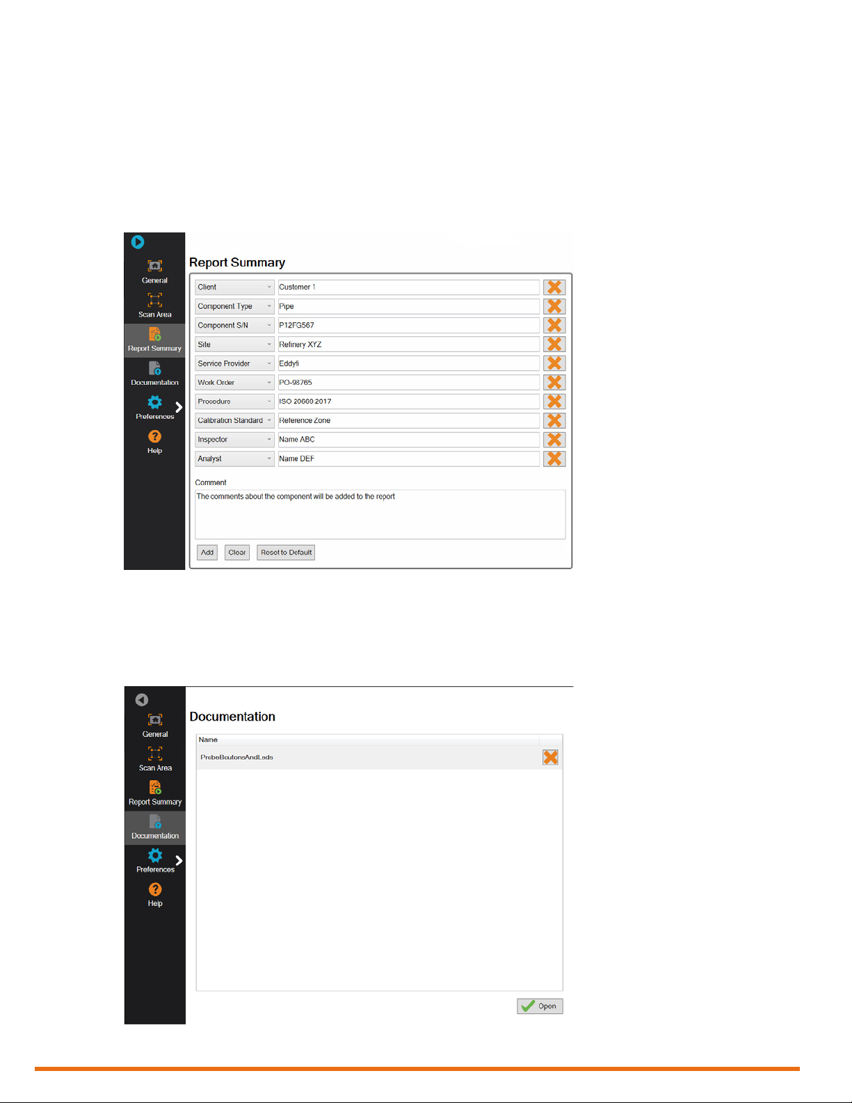
Report Summary Section
This section of the backstage serves to congure the summary included with your reports. This is where
you can:
• Add information about the component type, serial number, operator, service company, etc.
• Create new information elds to be included in reports
• Add comments about the component inspection
Figure 9 Backstage view: Report Summary
Documentation Section
This section of the backstage allows you to open PDFs located in the UserData folder of the in s t rument .
Opening a PDF here can display the document full page for easier reading.
Figure 10 Backstage view: Documentation
16 | www.eddy.com
 Loading...