

Eddyfi technologies Inuktun VT150 User Manual
2569 Kenworth Road, Suite C
Nanaimo, BC, V9T 3M4
CANADA
+1.250.729.8080
info@eddyfitechnologies.com
www.eddyfitechnologies.com

VT150 Vertical Crawler™
Document: UMDW013977.docm
Revision: A07
Created by: MDM
Date: 26 Sep 2019
3075042-A07
Source Location: C:\ePDM\ISLEng\products\dw-versatrax150mkii\manuals\UMDW013977.docm
Page 2 of 31
User Manual
Table of Contents
Table of Contents .......................................................................................................................................... 2
About This Manual ........................................................................................................................................ 4
System Description ....................................................................................................................................... 4
Specifications ............................................................................................................................................ 5
Certification ............................................................................................................................................... 5
Safety ........................................................................................................................................................ 5
Personal Safety Equipment ................................................................................................................... 5
Equipment Safety ................................................................................................................................... 6
Operational Safety ................................................................................................................................. 6
System Setup ................................................................................................................................................ 7
Working Environment ............................................................................................................................... 7
System Power & Line Voltage Set ............................................................................................................ 7
Power Requirements ............................................................................................................................. 7
Set the Line Voltage............................................................................................................................... 8
Generators / Inverters ............................................................................................................................ 8
Connections - Preconfigured Control Rack .............................................................................................. 8
Pre-Configured Control Rack ................................................................................................................. 8
Control System Connections – Copper Tether ...................................................................................... 9
Control System Connections – fiber optic tether ................................................................................. 10
Client Configured Rack ........................................................................................................................ 12
Connections - Vehicle & Tether .............................................................................................................. 13
Winch Installation .................................................................................................................................... 14
Portable Reel Setup ................................................................................................................................ 14
Tether Handling ...................................................................................................................................... 15
Connector Handling ................................................................................................................................ 16
Camera Installation ................................................................................................................................. 17
Minitrac™ Installation/Removal .............................................................................................................. 19

VT150 Vertical Crawler™
Document: UMDW013977.docm
Revision: A07
Created by: MDM
Date: 26 Sep 2019
3075042-A07
Source Location: C:\ePDM\ISLEng\products\dw-versatrax150mkii\manuals\UMDW013977.docm
Page 3 of 31
User Manual
Track Extensions .................................................................................................................................... 20
System Operation ....................................................................................................................................... 21
Pre-Operations Check ............................................................................................................................ 21
Post-Operations Check ........................................................................................................................... 22
Power-Up Sequence ............................................................................................................................... 22
Ground Fault Detection & Alarms ........................................................................................................... 22
Inuktun Control - ICON & InPro .............................................................................................................. 23
Dealing With Obstacles .......................................................................................................................... 24
Inspection Guidelines ............................................................................................................................. 24
Powered Winch Operation ...................................................................................................................... 24
Vehicle Recovery .................................................................................................................................... 25
Troubleshooting ...................................................................................................................................... 25
Camera Control Problems ................................................................................................................... 25
Video Problems .................................................................................................................................... 26
Vehicle Problems ................................................................................................................................. 26
Winch Problems ................................................................................................................................... 27
Parts and Repairs ....................................................................................................................................... 28
Ordering Parts/Customer Service ........................................................................................................... 28
Warranty Repairs .................................................................................................................................... 28
Factory Returns to Canada ..................................................................................................................... 29
Product/System Drawing Package Availability ....................................................................................... 29
Fuse Replacement .................................................................................................................................. 30
Fuse Diagnostics .................................................................................................................................... 30
Interface Box Fuse ............................................................................................................................... 30
Vehicle Power Fuse ............................................................................................................................. 30
Input Fuse (Power Supply Rack) ......................................................................................................... 30
Tether Re-termination ............................................................................................................................. 30
Limited Warranty Policy .............................................................................................................................. 31

VT150 Vertical Crawler™
Document: UMDW013977.docm
Revision: A07
Created by: MDM
Date: 26 Sep 2019
3075042-A07
Source Location: C:\ePDM\ISLEng\products\dw-versatrax150mkii\manuals\UMDW013977.docm
Page 4 of 31
User Manual
About This Manual
This manual has been prepared to assist you in the operation and maintenance of your Eddyfi
Technologies Inuktun equipment. Correct and prudent operation rests with the operator who must
thoroughly understand the operation, maintenance, service and job requirements. The specifications and
information in this manual are current at the time of printing.
This product is continually being updated and improved. Therefore, this manual is meant to explain and
define the functionality of the product. Furthermore, schematics or pictorials and detailed functionality
may differ slightly from what is described in this manual.
Eddyfi Technologies reserves the right to change and/or amend these specifications at any time without
notice. Customers will be notified of any changes to their equipment.
Information in this manual does not necessarily replace specific regulations, codes, standards, or
requirements of others such as government regulations.
This manual is copyright © 2019 by Inuktun Services Ltd. All rights reserved.
System Description
The Inuktun VT150 Vertical Crawler™ system is a Minitrac™ based vehicle used for navigating pipelines
ranging from 380mm to 915mm (15 inches to 36 inches) internal diameter. A minimized vehicle profile
provides maximum clearance for passage of service intrusions in the pipe.
The inspection system has been manufactured with the hazards and demands of pipe inspection in mind.
All Versatrax™ hardware can be used dry, underwater, or in dirty, muddy conditions. The rugged design
ensures a long service life and helps protect the vehicle from damage during normal use.
Typical applications include inspection of:
• Sewer and storm drains
• Hydroelectric pipe and infrastructure
• Steam headers
• Tanks and pressure vessels
• Oil and gas refineries and pipelines
• Pulp and paper mills

VT150 Vertical Crawler™
Document: UMDW013977.docm
Revision: A07
Created by: MDM
Date: 26 Sep 2019
3075042-A07
Source Location: C:\ePDM\ISLEng\products\dw-versatrax150mkii\manuals\UMDW013977.docm
Page 5 of 31
User Manual
Specifications
*Pipe Size Range
Standard Link,
Track Inner Position
Minimum: Ø381mm / Ø15in
Maximum: Ø559mm / Ø22in
Standard Link,
Track Outer Position
Minimum: Ø457mm / Ø18in
Maximum: Ø660mm / Ø26in
Longer Link,
Track Outer Position
Minimum: Ø559mm / Ø22in
Maximum: Ø914mm / Ø36in
Camera
Spectrum 90™ Pan, Tilt, Zoom Camera in Aluminum
Tracks
8000 Series Aluminum Minitracs™
Operating Temperature
0 - 40˚C / 32 - 104˚F
Storage Temperature
-20 - 60˚C / 4 - 140˚F
Depth Rating
(for chassis, tracks, cameras, lights)
60m/200ft
Vehicle Weight
**kg/***lb (weight may vary depending on configuration)
Power Input
Switchable between 120VAC/50-60Hz and 220VAC/50-60Hz,
3080 Watts Peak
*Specified diameters are internal diameters of pipe
Certification
The Versatrax 150™ system is built in accordance with the Low Voltage Directive 2006/95/EC, Machinery
Directive 2006/42/EC, and Electromagnetic Compatibility Directive 2004/108/EC.
Safety
Personal Safety Equipment
Observe all safety regulations required by law in your place of work. These typically include:

VT150 Vertical Crawler™
Document: UMDW013977.docm
Revision: A07
Created by: MDM
Date: 26 Sep 2019
3075042-A07
Source Location: C:\ePDM\ISLEng\products\dw-versatrax150mkii\manuals\UMDW013977.docm
Page 6 of 31
User Manual
• Traffic safety protocols
• Standard personal safety equipment including:
o Steel Toed Boots
o Safety Vests
o Hard Hats
o Gloves
• Heavy lifting procedures
• Overhead lifting protocols
Equipment Safety
Some precautions should be taken to protect the Versatrax™ system from damage:
• Repair damaged wires before operating the vehicle. A short circuit may damage the power system,
telemetry system, cameras, or any attached equipment.
• Never drop the vehicle. Although built tough, the vehicle is heavy and can suffer structural damage
when dropped.
• Prevent impact to the front of the 801 lights, Spectrum 90/120™ camera and Crystal Cam® camera
as they can suffer damage.
Operational Safety
• All personnel operating or maintaining this equipment must read and understand the operations
and maintenance manual prior to system operation.
• All personnel operating or maintaining this equipment must be competently trained.
• Appropriate personal protective equipment (PPE) must be worn while operating and maintaining
the equipment.
• The power supply is equipped with a ground fault interrupt circuit. Do not cheat or bypass the
ground fault interrupt circuit. Do not power the equipment from a source other than the provided
power supply.
• Caution: Spark Hazard - Under no circumstances should this equipment be used in a potentially
explosive atmosphere.
• Caution: High Voltage - The tether carries 400VDC to the rear harness block, and the
Minitrac™ whips carry 400VDC from the harness block to the tracks. Keep the tether capped at
all times when not installed on the vehicle. Follow the guidelines for preventing tether damage.
Do not operate with a damaged tether or Minitrac™ whip. 400VDC can cause serious injury or
death. Repair damaged wires before operating the vehicle. A short circuit may damage the
controller, cameras, or any attached equipment.
• Disconnect the power source before servicing the product; otherwise, damage or fatal injury may
result.
• Caution: Trip Hazard - Never stand on the tether. The vehicle and winch are strong enough to
pull it out from underneath you and cause you to fall. Standing on the tether may also cause
damage to the internal conductors and decrease the life of the protective jacket.
!
!
!

VT150 Vertical Crawler™
Document: UMDW013977.docm
Revision: A07
Created by: MDM
Date: 26 Sep 2019
3075042-A07
Source Location: C:\ePDM\ISLEng\products\dw-versatrax150mkii\manuals\UMDW013977.docm
Page 7 of 31
User Manual
• Caution: High Temperature - Both the integrated harness block and the 801 lights may become
extremely hot during operation. Always wear protective gloves when handling these parts of the
vehicle after they have been in use.
• Caution: Intense Optical Radiation - The 801 lights and Spectrum™ camera lights are
extremely bright. Never look directly at the lights or even from a shallow angle. Always use a
welding filter (shade #8 or higher) when inspecting the LEDs.
• Caution: Pinching Hazard - There is a possibility that one’s fingers could be drawn into the
tracks should they be activated when the vehicle is being handled, or they may be pinched or
severed by the expand mechanism. To avoid this hazard do not connect the tether to the
portable controller until the vehicle is configured, placed, and ready to use. If the vehicle is being
tested, do not connect the tether until handling of the vehicle is complete. If the vehicle is
permanently installed onto a van or trailer and the tether cannot be disconnected, turn off the
power.
• Establish a communication protocol between the person handling the vehicle and the operator at
the computer. It is the operator’s responsibility to check and ask if it is safe to power up the
vehicle or initiate movement.
System Setup
Working Environment
The control rack (computer, power supply, interface box) are to be used in a dry, covered environment
only. These components are not waterproof. Keep all cords and cables away from water. The
recommended controller and power supply operating temperatures are between 0˚C - 40˚C (32˚F 104˚F).
The tether and vehicle are depth rated to 60 meters (200 feet) of water. The tether connector is a drymate type which must be dry when connected to the vehicle. Keep the tether connector capped with a
dummy plug when not connected to the vehicle to help keep out dirt. The tracks are tolerant to sand and
muddy conditions, although this decreases seal life. The vehicle may also be operated in dry or dusty
environments in the recommended operating temperature range of 0°C - 40°C (32°F - 104°F).
The winch and portable reel are splash resistant only. Refer to the winch or reel manual.
System storage temperatures are between -20˚C - 60˚C (-4˚F - 140˚F).
System Power & Line Voltage Set
Power Requirements
The power requirements given below are maximums for a fully configured system with cable reel. For
use with 110VAC source, a fully configured Versatrax™ system requires three independent standard 15Amp circuits for power, or one 20-Amp and one 15-Amp circuits as follows.
Control Computer
500W
15-Amp 110VAC Circuit #1
!!!

VT150 Vertical Crawler™
Document: UMDW013977.docm
Revision: A07
Created by: MDM
Date: 26 Sep 2019
3075042-A07
Source Location: C:\ePDM\ISLEng\products\dw-versatrax150mkii\manuals\UMDW013977.docm
Page 8 of 31
User Manual
Set the Line Voltage
Before powering on the Versatrax™ system, it is important to check that the input voltage settings are
correct - an incorrect voltage setting will damage the system power supply and the winch controller.
When installing the system in a new location always check the line voltage.
• Monitor: Universal - no action required.
• Computer: Universal - no action required.
• Interface Box: Universal - no action required.
• Power Supply: Set the line voltage switch to 115/230VAC and change fuse.
• For 115VAC use 15A MDA type fuse.
• For 230VAC use 10A MDA type fuse.
• Winch: Jumpers must be set inside the hand-held controller. Refer to the winch manual for
instructions.
Generators / Inverters
If powering the system from a generator or inverter, refer to that unit’s operating manual for
recommendations on continuous and peak load ratings. These power sources may apply a reduced
output rating based on electrical load and environmental temperature. Remember to include the power
needs of any other connected devices (external monitors, recording devices, lighting, etc.) when selecting
a generator or inverter.
Connections - Preconfigured Control Rack
Pre-Configured Control Rack
The monitor, computer, interface box and power supply are installed and connected in a shock-mount
portable 19-inch rack case. Systems pre-configured in a control rack will only need the tether, winch and
vehicle connections to be made before operations as described below.
Monitor
80W
20-Amp 110VAC Circuit
#1
Power Supply and
Vehicle
1300W
15-Amp 110VAC Circuit #2
Powered Winch
1200W
15-Amp 110VAC Circuit #3
15-Amp 110VAC Circuit
#2
System Total
3080W
VT150 Vertical Crawler™
Document: UMDW013977.docm
Revision: A07
Created by: MDM
Date: 26 Sep 2019
3075042-A07
Source Location: C:\ePDM\ISLEng\products\dw-versatrax150mkii\manuals\UMDW013977.docm
Page 9 of 31
User Manual
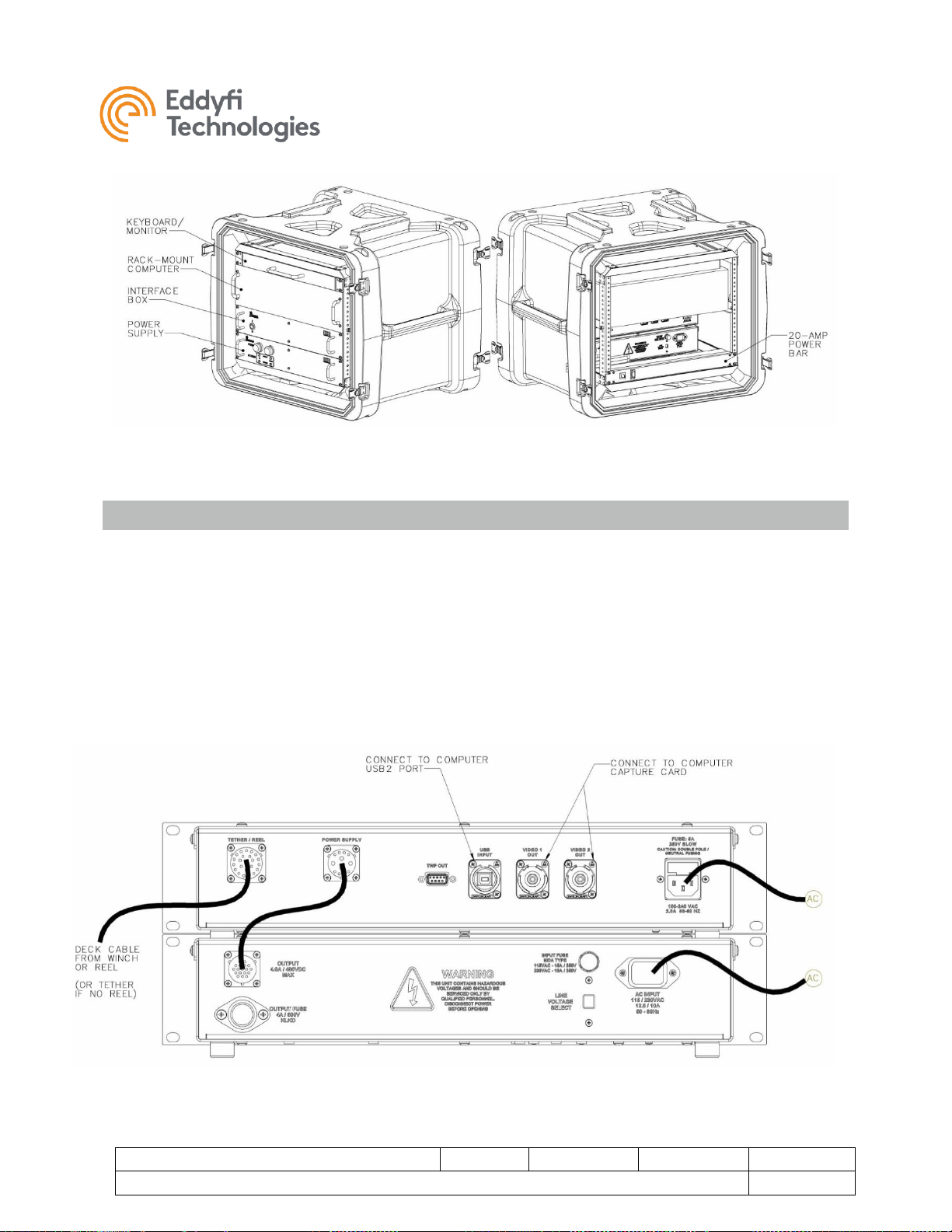
FIGURE 1: CONTROL RACK CONFIGURATION
Control System Connections – Copper Tether
1. Connect the power supply to the interface box using the supplied interface cable. Ensure the
locking collars are screwed on all the way.
2. Connect the keyboard/monitor/mouse/system speakers to the computer. These are standard
computer connections.
3. Using equipment power cords, connect the monitor, computer, interface box and system power
supply to the 20-Amp power bar. Note that the power bar will only accept equipment power
cords. The input cord on the power bar can be changed depending on the input voltage and
location.
4. Connect the tether (or deck cable from the winch or reel) to the interface box as illustrated below.
FIGURE 2: POWER SUPPLY & INTERFACE BOX

VT150 Vertical Crawler™
Document: UMDW013977.docm
Revision: A07
Created by: MDM
Date: 26 Sep 2019
3075042-A07
Source Location: C:\ePDM\ISLEng\products\dw-versatrax150mkii\manuals\UMDW013977.docm
Page 10 of 31
User Manual
Control System Connections – fiber optic tether
Systems equipped with a fiber optic tether employ a fiber bundle running down the middle of the tether to
transmit communications and video to and from the vehicle. The fiber bundle is typically terminated inside
the winch and comes out as two fiber connectors (which look like small BNC connectors) underneath the
bearing box.
Here are some basic rules for handling fiber optic cables and connectors to ensure system performance:
• When not connected, always keep the fiber optic patch cables capped to protect the ends from dirt
and contamination. Keep the connectors on the interface box and winch capped for the same
reason.
• When caps are removed, immediately place them in a clean zip-lock bag to keep the caps free
from dirt and contamination.
• Don’t let the ends of the patch cable contact or strike any surfaces. Contact may scratch or chip
the end.
• Avoid touching the exposed end with your fingers. This will leave oil residue and may cause a
decrease in signal strength.
• The minimum bend radius for a fiber optic cable is about 2 inches [50mm]. Sharper bends may
degrade the signal. If a very sharp bend or kink occurs – don’t worry – these typically don’t break
the cable; they just cause signal loss until the bend or kink is straightened out.
• If tie-wraps are used to constrain a fiber patch cable, leave them loose – do not overtighten. Tie-
wraps can cause sharp local bends which degrade the signal.
• If you regularly connect and disconnect fiber optic cables, we strongly suggest you obtain a fiber
connector cleaning kit.
Top – End cable connections for a fiber optic system:
1. Connect the power supply to the interface box using the supplied interface cable. Ensure the
locking collars are screwed on all the way.
2. Connect the keyboard/monitor/mouse/system speakers to the computer. These are standard
computer connections.
3. Using equipment power cords, connect the monitor, computer, interface box and system power
supply to the 20-Amp power bar. Note that the power bar will only accept equipment power
cords. The input cord on the power bar can be changed depending on the input voltage and
location.
4. Connect the tether (or deck cable from the winch or reel) to the interface box as illustrated below.
5. Connect the fiber optic cables from the winch to the interface box. Match connectors 1 & 2 on the
winch to the same connector number on the interface box. Follow the fiber optic handling
guidelines given above.
6. Connect the SD-1 (standard definition #1) output to the video capture card in the computer. This
is the system Rear Video.
7. Connect the HD-SDI output to the computer HD-SDI video capture card. This is the system front
High Definition Camera.
8. Connect the USB to a computer USB-2 port. This is vehicle communications.
 Loading...