

Eddyfi technologies Inuktun Versatrax 300 User Manual
2569 Kenworth Road, Suite C
Nanaimo, BC, V9T 3M4
CANADA
+1.250.729.8080
info@eddyfitechnologies.com
www.eddyfitechnologies.com
INUKTUN VERSATRAX 300™

Versatrax 300™
Document: UMBH008532.docm
Revision: A07
Created by: KJB
Date: 26 Sep 2019
3047763-A07
Source Location: C:\ePDM\ISLEng\products\bh-vt300series4-trackchassis\manuals\UMBH008532.docm
Page 2 of 67
Versatrax 300 User Manual
For IBA 5954
Table of Contents
About This Manual ........................................................................................................................................ 6
Specifications ................................................................................................................................................ 6
Safety ............................................................................................................................................................ 7
Personnel Safety ...................................................................................................................................... 8
Personal Safety Equipment ................................................................................................................... 8
Operational Safety .................................................................................................................................... 8
Equipment Safety ..................................................................................................................................... 9
System Setup ................................................................................................................................................ 9
Working Environment ............................................................................................................................... 9
Typical Installation ................................................................................................................................. 9
Personnel Requirements ..................................................................................................................... 10
Power Requirements ........................................................................................................................... 10
Input Voltage Transformer ................................................................................................................... 11
Unpacking the System ............................................................................................................................ 11
Power Supply Rack Installation .............................................................................................................. 12
Computer Cable Hookup ........................................................................................................................ 12
Winch Installation .................................................................................................................................... 15
Working Environment........................................................................................................................... 15
Power Requirements ........................................................................................................................... 15
Bolt Down ............................................................................................................................................. 15
Vehicle Handling Equipment................................................................................................................... 16
Boom Arm & Cable Hoist ..................................................................................................................... 16
Configuration ............................................................................................................................................... 16
Configuration Bench ............................................................................................................................ 16
Parallel Vehicle Configuration................................................................................................................. 16
Minitrac™ Installation & Removal ........................................................................................................... 17
Tether Hook-Up ...................................................................................................................................... 17

Versatrax 300™
Document: UMBH008532.docm
Revision: A07
Created by: KJB
Date: 26 Sep 2019
3047763-A07
Source Location: C:\ePDM\ISLEng\products\bh-vt300series4-trackchassis\manuals\UMBH008532.docm
Page 3 of 67
Versatrax 300 User Manual
For IBA 5954
Camera Installation ................................................................................................................................. 19
Auxiliary Light Installation ....................................................................................................................... 20
Rear Camera Installation ........................................................................................................................ 21
Auxiliary Camera Installation .................................................................................................................. 22
Sonar Installation .................................................................................................................................... 24
Ethernet .................................................................................................................................................. 24
Pinout for MCBH6F Subconn Bulkhead - Ethernet ............................................................................. 25
RS-232 .................................................................................................................................................... 25
Pinout for MCBH5F Subconn Bulkhead – RS232 ............................................................................... 25
Size Configuration 12in – 36in – Flat ...................................................................................................... 26
Track Extensions – Chassis Mark Conversion Chart .......................................................................... 27
Traction Weights .................................................................................................................................. 28
Camera Raise Extension ........................................................................................................................ 29
Track Extensions .................................................................................................................................... 30
Wire Harness Routing ............................................................................................................................. 31
Inline Vehicle Configuration (6-8-10-12) ..................................................................................................... 36
Installing the Tracks ................................................................................................................................ 36
Installing The Spectrum 90™ Camera ................................................................................................... 39
Camera Height / Guide Wheel Adjustment ............................................................................................. 40
Rear Camera Installation (In-line) ........................................................................................................... 41
Traction Enhancement (In-Line) ............................................................................................................. 41
Operation..................................................................................................................................................... 44
Communication ....................................................................................................................................... 44
Tether Handling ...................................................................................................................................... 44
Connector Handling ................................................................................................................................ 45
Power Interface Box ............................................................................................................................... 46
Power Indicators & Alarms .................................................................................................................. 46
Power Interface Box ............................................................................................................................. 46

Versatrax 300™
Document: UMBH008532.docm
Revision: A07
Created by: KJB
Date: 26 Sep 2019
3047763-A07
Source Location: C:\ePDM\ISLEng\products\bh-vt300series4-trackchassis\manuals\UMBH008532.docm
Page 4 of 67
Versatrax 300 User Manual
For IBA 5954
Controls and Indicators ........................................................................................................................ 46
Power Fuses ........................................................................................................................................... 47
Interface Box Fuse ............................................................................................................................... 47
Vehicle Power Fuse ............................................................................................................................. 47
Main Power Breaker ............................................................................................................................ 47
Ground Fault Detection ........................................................................................................................... 48
Power Up / Power Down ...................................................................................................................... 48
Power-ON Notes .................................................................................................................................. 49
Power-OFF Notes ................................................................................................................................ 49
Fiber Interface Box ................................................................................................................................. 49
Pre / Post Operations Check .................................................................................................................. 50
Vehicle Deployment ................................................................................................................................ 50
Vehicle Recovery .................................................................................................................................... 50
Winch Operation ......................................................................................................................................... 52
Winch Safety ........................................................................................................................................... 52
Pre-Operations Inspection ...................................................................................................................... 52
Winch Operation ..................................................................................................................................... 52
Un-spooling The Tether .......................................................................................................................... 53
Spooling The Tether ............................................................................................................................... 54
Automatic Level Wind ............................................................................................................................. 54
Control Box .......................................................................................................................................... 54
Operation ............................................................................................................................................. 54
Level Wind Controls ............................................................................................................................. 54
Level Wind Calibration ......................................................................................................................... 55
Free-Wheeling Spool ........................................................................................................................... 55
Drum Brake .......................................................................................................................................... 56
Manual Cranking .................................................................................................................................. 56
Dealing with Obstacles ........................................................................................................................... 56
Inspection Guidelines ............................................................................................................................. 56
Maintenance ................................................................................................................................................ 57

Versatrax 300™
Document: UMBH008532.docm
Revision: A07
Created by: KJB
Date: 26 Sep 2019
3047763-A07
Source Location: C:\ePDM\ISLEng\products\bh-vt300series4-trackchassis\manuals\UMBH008532.docm
Page 5 of 67
Versatrax 300 User Manual
For IBA 5954
Fuse Replacement .................................................................................................................................. 57
Minitrac™ Maintenance .......................................................................................................................... 57
Camera Maintenance ............................................................................................................................. 57
701 LED-Bulb Replacement ................................................................................................................... 57
Tether Re-termination ............................................................................................................................. 58
Troubleshooting .......................................................................................................................................... 58
Camera Control Problems ................................................................................................................... 58
Video Problems .................................................................................................................................... 58
Vehicle Problems ................................................................................................................................. 59
Winch Problems ................................................................................................................................... 60
Vehicle Recovery ................................................................................................................................. 60
Annex B ....................................................................................................................................................... 62
Pre-Operation Check ........................................................................................................................... 62
Post-Operation Check ............................................................................................................................ 64
Parts and Repairs ....................................................................................................................................... 65
Ordering Parts/Customer Service ........................................................................................................... 65
Warranty Repairs .................................................................................................................................... 65
Factory Returns to Canada ..................................................................................................................... 65
Product/System Drawing Package Availability ....................................................................................... 66
Limited Warranty Policy .............................................................................................................................. 67

Versatrax 300™
Document: UMBH008532.docm
Revision: A07
Created by: KJB
Date: 26 Sep 2019
3047763-A07
Source Location: C:\ePDM\ISLEng\products\bh-vt300series4-trackchassis\manuals\UMBH008532.docm
Page 6 of 67
Versatrax 300 User Manual
For IBA 5954
About This Manual
This manual has been prepared to assist you in the operation and maintenance of your Eddyfi
Technologies Inuktun equipment. Correct and prudent operation rests with the operator who must
thoroughly understand the operation, maintenance, service and job requirements. The specifications and
information in this manual are current at the time of printing.
This product is continually being updated and improved. Therefore, this manual is meant to explain and
define the functionality of the product. Furthermore, schematics or pictorials and detailed functionality
may differ slightly from what is described in this manual.
Eddyfi Technologies reserves the right to change and/or amend these specifications at any time without
notice. Customers will be notified of any changes to their equipment.
Information in this manual does not necessarily replace specific regulations, codes, standards, or
requirements of others such as government regulations.
This manual copyright © 2019 by Inuktun Services Ltd. All rights reserved.
Specifications
Tether Length
2,130 m (7,000 ft)
Chassis Configuration
Tandem Parallel Chassis
Vehicle Weight
104 kg (230 lb) with full configuration)
Power Requirements
Winch
120VAC, dedicated 15 Amp circuit
Control Computer
120VAC, standard 15 Amp circuit
Power Supply
120VAC, dedicated 25 Amp circuit, L5-30 type
plug
Pipe Diameter Range
12in to 24in
Camera Centered
Up to 56in
Camera Centered with Extensions
56in to Flat
Continuous Adjustment
Operating Temperature
0 º -50 ºC (32 º -122 ºF) * *Dependent on
operating conditions. Ask your sales expert for
more information.

Versatrax 300™
Document: UMBH008532.docm
Revision: A07
Created by: KJB
Date: 26 Sep 2019
3047763-A07
Source Location: C:\ePDM\ISLEng\products\bh-vt300series4-trackchassis\manuals\UMBH008532.docm
Page 7 of 67
Versatrax 300 User Manual
For IBA 5954
Front Facing Camera
Spectrum 90™
Optional:
Spectrum 120HD™ high definition camera main
camera, middle and/or rear-facing camera
Rear & Auxiliary Camera
Crystal Cam®
Minimum Vehicle Dimensions
1651 x 371 x 434 mm
(65 x 14.6 x 17.1 in)
Nominal Pulling Capacity
200lb
Max Speed
9 m (30 ft) per minute
Depth Rating
60 m (200 ft)
Conditions
All vehicle hardware can be used in dry, dusty
conditions or underwater in dirty, muddy
conditions
Safety
• All personnel operating or maintaining this equipment must read and understand the operations and
maintenance manual prior to system operation.
• All personnel operating or maintaining this equipment must be competently trained.
• Appropriate personal protective equipment (PPE) must be worn while operating and maintaining the
equipment.
• Under no circumstances should this equipment be used in a potentially explosive atmosphere.
• If the equipment is powered from a source other than an Eddyfi provided controller, the power
supplied to the product must have reinforced isolation from the mains with no reference to earth
ground.
Caution: Disconnect the power source before servicing the product; otherwise, damage may result.
Caution: Pinching Hazard - There is a pinching hazard around the chassis “X” hinges and the
camera swivel mount. Do not lift or handle the vehicle from these areas. Use the handles
provided for safe handling.
Warning: Shock Hazard. 420 Volts DC. Turn off the power before servicing, connecting, or
disconnecting any of these components: power control rack, deck cable, winch, tether, vehicle
telemetry can.

Versatrax 300™
Document: UMBH008532.docm
Revision: A07
Created by: KJB
Date: 26 Sep 2019
3047763-A07
Source Location: C:\ePDM\ISLEng\products\bh-vt300series4-trackchassis\manuals\UMBH008532.docm
Page 8 of 67
Versatrax 300 User Manual
For IBA 5954
Personnel Safety
Personal Safety Equipment
Observe all safety regulations required by law in your place of work. These will typically include:
• Traffic safety protocols
• Standard Personal Safety Equipment including:
o Steel toed boots
o Safety vests
o Hard hats
o Gloves
• Heavy lifting procedures.
• Overhead lifting protocols.
Operational Safety
Your personal safety is the most important of all. Here are a few things to watch out for:
• Take care when using cranes or overhead equipment for vehicle deployment. Watch for
overhead cables and take appropriate safety precautions (hard hats, steel-toed boots, gloves,
etc.)
• Never stand on the tether. The vehicle and winch are strong enough to pull it out from under you
and cause you to fall. Standing on the tether can also damage the tether.
• The tether carries 420 VDC for vehicle power. Keep the tether termination power connector
capped when not plugged into the vehicle. Follow the guidelines for preventing tether damage.
Do not operate the system with a damaged tether.
• The LED lights are very bright. Do not look directly into the lights.
Warning: Shock Hazard! 420 Volts DC Turn off the power before servicing,
connecting, or disconnecting any of these components:
• Interface box
• Deck cable
• Winch
• Tether
• Vehicle telemetry can
•
Warning: High Intensity lights. Do not look directly into the lights. Use a welding filter (shade
#8) to observe the light elements.

Versatrax 300™
Document: UMBH008532.docm
Revision: A07
Created by: KJB
Date: 26 Sep 2019
3047763-A07
Source Location: C:\ePDM\ISLEng\products\bh-vt300series4-trackchassis\manuals\UMBH008532.docm
Page 9 of 67
Versatrax 300 User Manual
For IBA 5954
Equipment Safety
Some precautions should be taken to protect the Versatrax 300™ system from damage:
• Repair any damaged wires before operating the vehicle. A short circuit may damage the
telemetry can, cameras, or any attached equipment.
• Never drop the vehicle. Although built tough, the vehicle is heavy and can suffer structural
damage when dropped.
System Setup
Working Environment
Controller – The controller is a rack-mount industrial computer system intended to be used in a dry,
covered environment only. The controller connectors are not waterproof. Keep all cords and cables away
from water. Recommended controller operating temperature is between 0 º and 50 ºC (32 º-122 °F)
Power Supply – The high voltage power supplies must be kept under cover and dry at all times.
Tether & Wiring Harnesses – The tether and vehicle wiring harnesses are depth rated to 100 feet (30m)
of water. Keep the power connector capped with a dummy plug when the tether is not connected to the
vehicle.
Winch – The winch is splash resistant only. Refer to the winch manual.
Vehicle – The Minitracs™, vehicle wiring harnesses and chassis are designed to work underwater up to
100 feet deep. The tracks are tolerant toward sandy and muddy conditions, although this decreases seal
life. The vehicle may also be operated in dry or dusty environments in the recommended operating
temperature range of 0 º -50 ºC (32 º to 122 ºF).
Storage – Allowable system storage temperatures are between -20 º and +70 ºC (0 º - 150 ºF).
Typical Installation
The following describes a typical installation scenario recommended by us.
A representative set up for a pipe inspection system is based on a covered two-ton or larger box truck.
The truck carries the power source (generator) and houses the power supply and control system in a dry,
covered environment. The computer / control console and recording equipment are placed in an officelike room built into the truck. The rear wall of the truck should open completely. A hoisting winch must be
installed to lift the vehicle during deployment. The winch, crane and other equipment can be mounted at
the back of the truck box near the door for easy deployment. The truck should also contain the
maintenance shop, ample bench space for maintaining and configuring the vehicle and system wash
down equipment.
The vehicle should be operated by a crew of at least two. Most importantly, a person should always be
available to tend the tether. This person may also play a role in vehicle inspection and deployment. A
second person drives the vehicle and operates the recording equipment.

Versatrax 300™
Document: UMBH008532.docm
Revision: A07
Created by: KJB
Date: 26 Sep 2019
3047763-A07
Source Location: C:\ePDM\ISLEng\products\bh-vt300series4-trackchassis\manuals\UMBH008532.docm
Page 10 of 67
Versatrax 300 User Manual
For IBA 5954
The operations crew should be able to communicate quickly with each other to allow fast response in
case of an emergency such as a tether hang up. It is recommended that a signal system be set up so that
the operators may work efficiently and safely as a team. It is always advantageous for both operators to
be aware of full system status.
Personnel Requirements
A typical pipe inspection van operation requires a minimum of two people. A third person is often needed
to aid in vehicle deployment and tether handling.
Console Operator – This person is responsible for driving the vehicle, watching the pipe and making
notes and comments about location and pipe situation. It is also the operator’s responsibility to assess
whether a pipe is in condition for safe passage of the vehicle or risk getting stuck. The operator may also
assist in general site setup (cones/ warning signs), vehicle maintenance and configuration.
Deployment / Tether Handler / Field Maintenance – This person has several tasks;
• Configure the vehicle for the current pipe
• Lower the vehicle into and out of the manhole
• Watch the tether as the vehicle enters and exits the pipe
• Operate the winch
Assistant / Winch Handler – This person assists with maintenance, lifting and winch operation. When
deploying the vehicle one person is need at the console, one to handle the tether and a third to operate
the cable hoist.
Power Requirements
This system requires two power circuits.
• Winch – 120VAC, standard 15 Amp circuit. It is recommended that the winch operate from its
own circuit independent of the control computer. The input voltage for the winch can be switched
to 240VAC by configuring the Penta Drive. See the winch manual for instructions on how to do
this. The Auto Level Wind supports 100-250VAC.
• Rack Mounted Control System – The rack mounted control system consists of the Control
Computer, Interface Box (Power Supplies), Fiber Interface Box and, the monitor and keyboard
tray. All rack mounted devices except the Interface Box (Power Supply) are connected to a Rack
Mounted Power Bar. The power cables for the Interface Box and the Power Bar are bundled
together and then joined to a single 120V 15A North American NEMA 5-15P plug. This plug must
only be connected to 120VAC mains.
o Control Computer – 120-240VAC, standard 15 Amp circuit. A surge protected UPS is
recommended to protect the computer from power failures. We also recommend that this
circuit be dedicated to the computer and monitors only.

Versatrax 300™
Document: UMBH008532.docm
Revision: A07
Created by: KJB
Date: 26 Sep 2019
3047763-A07
Source Location: C:\ePDM\ISLEng\products\bh-vt300series4-trackchassis\manuals\UMBH008532.docm
Page 11 of 67
Versatrax 300 User Manual
For IBA 5954
o Interface Box (Power Supply) – 120VAC, 25 Amp circuit; L5-30 type locking plug. This
circuit must be dedicated to the vehicle.
o Fiber Interface Box – 100-250VAC, 3.15A.
o Monitor and Keyboard Tray – 100-240VAC.
o Rack Mounted Power Bar – 120VAC, standard 15 Amp circuit; NEMA 5-15P plug.
Input Voltage Transformer
Voltage Transformer – In order to support system operation around the world, a voltage transformer
is included with the system. Both the Rack Mounted Power Bar and the Interface Box must be
connected to this voltage transformer whenever the system is to be powered from 200-240VAC. The
Interface Box (Power Supply) and the Rack Mounted Power Bar cords are bundled together and
joined to a single NEMA 5-15P plug which can be plugged directly into the voltage transformer.
Note: The voltage selection jumper on the back of the voltage transformer must be set to the
appropriate mains voltage which the voltage transformer will be connected to.
Warning: The VT300 system may be damaged if the voltage selection jumper on the back of
the input system voltage transformer is set incorrectly.
Unpacking the System
The system is packed into two wooden crates for shipping and storage. Remove the Phillips-head screws
at the bottom of the crates to lift off the covers. One crate contains the winch and the other contains the
vehicle and control computer.
An overhead crane or engine hoist will be needed to move the winch from the crate base to its installed
position.
Note: The crates are for shipping and storage only – not for system deployment.
Note: If the system is to be shipped or stored for any length of time, we recommend that it be packed
into its original shipping crate.
Versatrax 300™
Document: UMBH008532.docm
Revision: A07
Created by: KJB
Date: 26 Sep 2019
3047763-A07
Source Location: C:\ePDM\ISLEng\products\bh-vt300series4-trackchassis\manuals\UMBH008532.docm
Page 12 of 67
Versatrax 300 User Manual
For IBA 5954
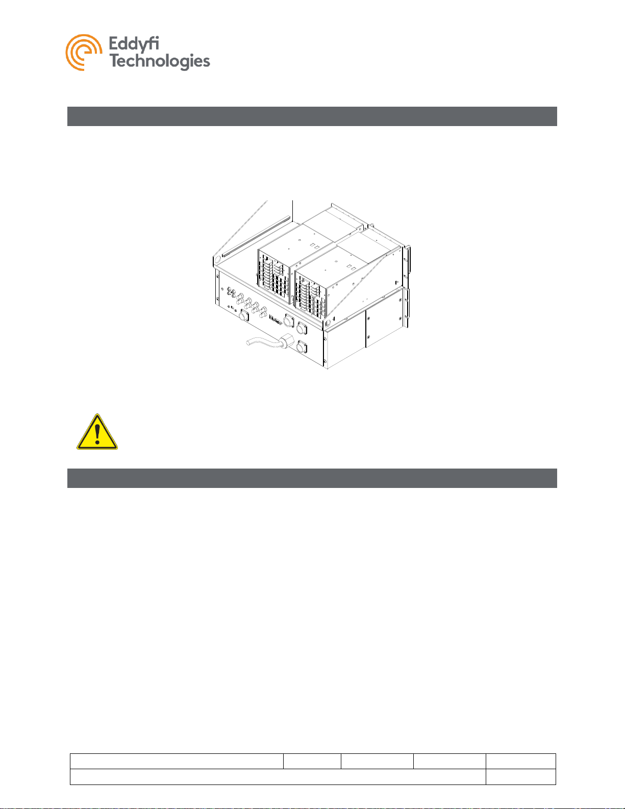
Power Supply Rack Installation
Mount the power supplies and interface box on a standard 19in rack-mount rail. The power supplies are
air cooled and require open circulation. The rack must be an open-face type with no front or back cover to
allow unimpeded cooling circulation. The power supplies draw air from the front and blow it out from the
back.
FIGURE 1: RACK-MOUNT POWER SUPPLIES & INTERFACE BOX
Warning: Failure to provide for enough air circulation will cause overheating and system
malfunction. Do not mount the power supplies in a closed-front rack.
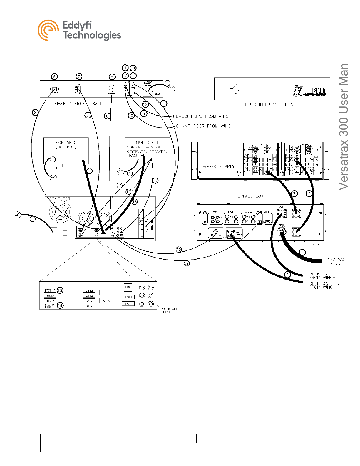
Computer Cable Hookup
The VT300™ control system consists of the computer, power interface box, fibre interface box and power
supply rack. The interface boxes provide a common connection point for vehicle power supplies, PC
controls, and communication for the system. The power interface box is also the main power input for the
vehicle and provides ground fault protection.
Use the following check list for cable hook-up, with reference to the Control Cable Hook-Up illustration
below.
1. Ensure the AC power cords are plugged into the internal power bar.
2. Vehicle Power L5-30 power plug to wall or generator.
3. PS1 and PS2 connected to interface box. The order of these plugs does not matter.
4. Connect the deck cables from the winch to the interface box.
a. Deck Cable 1 from winch to Interface Box.
b. Deck Cable 2 from winch to Interface Box.
c. HD-SDI fibre from winch to Fibre Interface Box (yellow patch cord).

Versatrax 300™
Document: UMBH008532.docm
Revision: A07
Created by: KJB
Date: 26 Sep 2019
3047763-A07
Source Location: C:\ePDM\ISLEng\products\bh-vt300series4-trackchassis\manuals\UMBH008532.docm
Page 13 of 67
Versatrax 300 User Manual
For IBA 5954
d. COMMS fibre from winch to Fibre Interface Box (yellow patch cord).
5. Vehicle COMMS to USB2 on the computer.
6. USB connection between fibre interface box and computer.
7. RS-232 between fibre interface box and USB2 on computer.
8. Ethernet connection between fibre interface box and computer.
9. SD video (auxiliary cameras) connected to the 8-Y-IN plug on the octopus connector.
10. HD-SDI video coax to the middle coax connector on the computer.
11. Optional second monitor connection.
12. Tray keyboard to USB
13. Tray trackpad to USB
14. Tray monitor to upper HDMI connector.
15. Tray speaker to the green audio connector.
16. Hermes RTL dongle
17. StreamPix dongle
18. Winch encoder USB connection to computer.
(Refer to image on next page)
Versatrax 300™
Document: UMBH008532.docm
Revision: A07
Created by: KJB
Date: 26 Sep 2019
3047763-A07
Source Location: C:\ePDM\ISLEng\products\bh-vt300series4-trackchassis\manuals\UMBH008532.docm
Page 14 of 67
Versatrax 300 User Manual
For IBA 5954
FIGURE 2: CONTROL CABLE HOOK-UP
Versatrax 300™
Document: UMBH008532.docm
Revision: A07
Created by: KJB
Date: 26 Sep 2019
3047763-A07
Source Location: C:\ePDM\ISLEng\products\bh-vt300series4-trackchassis\manuals\UMBH008532.docm
Page 15 of 67
Versatrax 300 User Manual
For IBA 5954
Winch Installation
Working Environment
The winch is intended for use in a dry covered environment. It is splash resistant and can withstand some
water spray. The drum is sealed so the tether can be wound on wet. Keep the winch out of standing
water. Working temperature range: 0 º - 50 °C (32 º - 122 °F). Storage temperature -20 º to 60 °C (0 º 140 °F).
Power Requirements
The winch connects to a standard 110VAC 60Hz. Power source fused at 15 Amps. A ground fault
protected (GFI) outlet is recommended.
The input voltage for the winch can be switched to 240VAC by configuring the Penta Drive. See the winch
manual for instructions on how to do this. The Auto Level Wind supports 100-250VAC.
If an inverter is used, ISL recommends a minimum of 1200 watts rating.
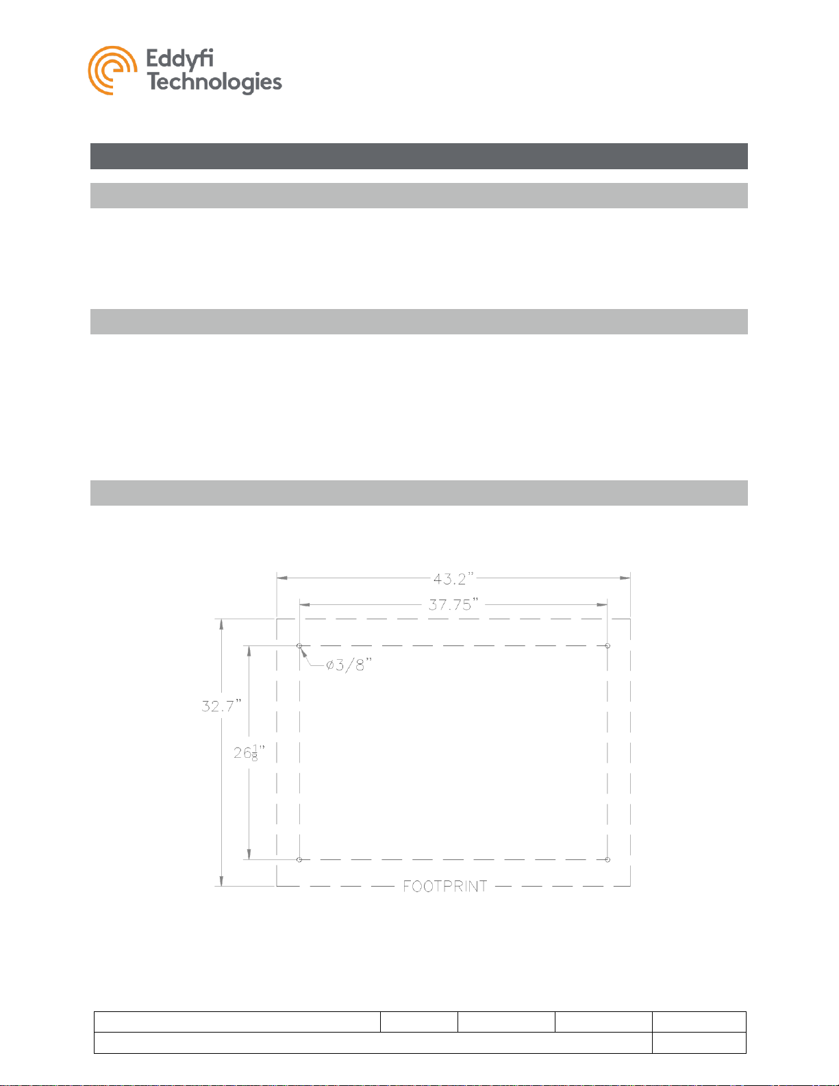
Bolt Down
The winch must be bolted down prior to use. Peak loads may be strong enough to pull an unsecured
winch out of the van. The figure below shows the bolt pattern for use with 3/8in bolts and large washers.
FIGURE 3: WINCH BOLT-DOWN PATTERN
Versatrax 300™
Document: UMBH008532.docm
Revision: A07
Created by: KJB
Date: 26 Sep 2019
3047763-A07
Source Location: C:\ePDM\ISLEng\products\bh-vt300series4-trackchassis\manuals\UMBH008532.docm
Page 16 of 67
Versatrax 300 User Manual
For IBA 5954
Vehicle Handling Equipment
Boom Arm & Cable Hoist
Because the vehicle is heavy some handling equipment is recommended with the system installation.
• The first of these is a swinging overhead boom for vehicle deployment which must hold the pay-
out sheave axle at least 9 feet above ground level. The capacity of the arm needs to be at least
½-tonne at full extension – enough for full vehicle weight plus full winch power.
• The pay-out sheave diameter should be at least 10in diameter to help prevent tether fatigue.
• An electric cable hoisting winch with at least ½-tonne load capacity is necessary to raise and
lower the vehicle. The cable on this hoist needs to be long enough for the deepest expected
deployment.
Configuration
Configuration Bench
You will need a dedicated work bench for vehicle configuration and maintenance. Ideally this is at least
30in x 60in and is accessible from both sides. The lower portions of the bench may be equipped with
racks or drawers where tools, spare parts and fasteners are kept.
A configuration fixture is provided with the VT300. This is a system of wooden stands and support blocks
used for installing the tracks, side weights and track extension plates.
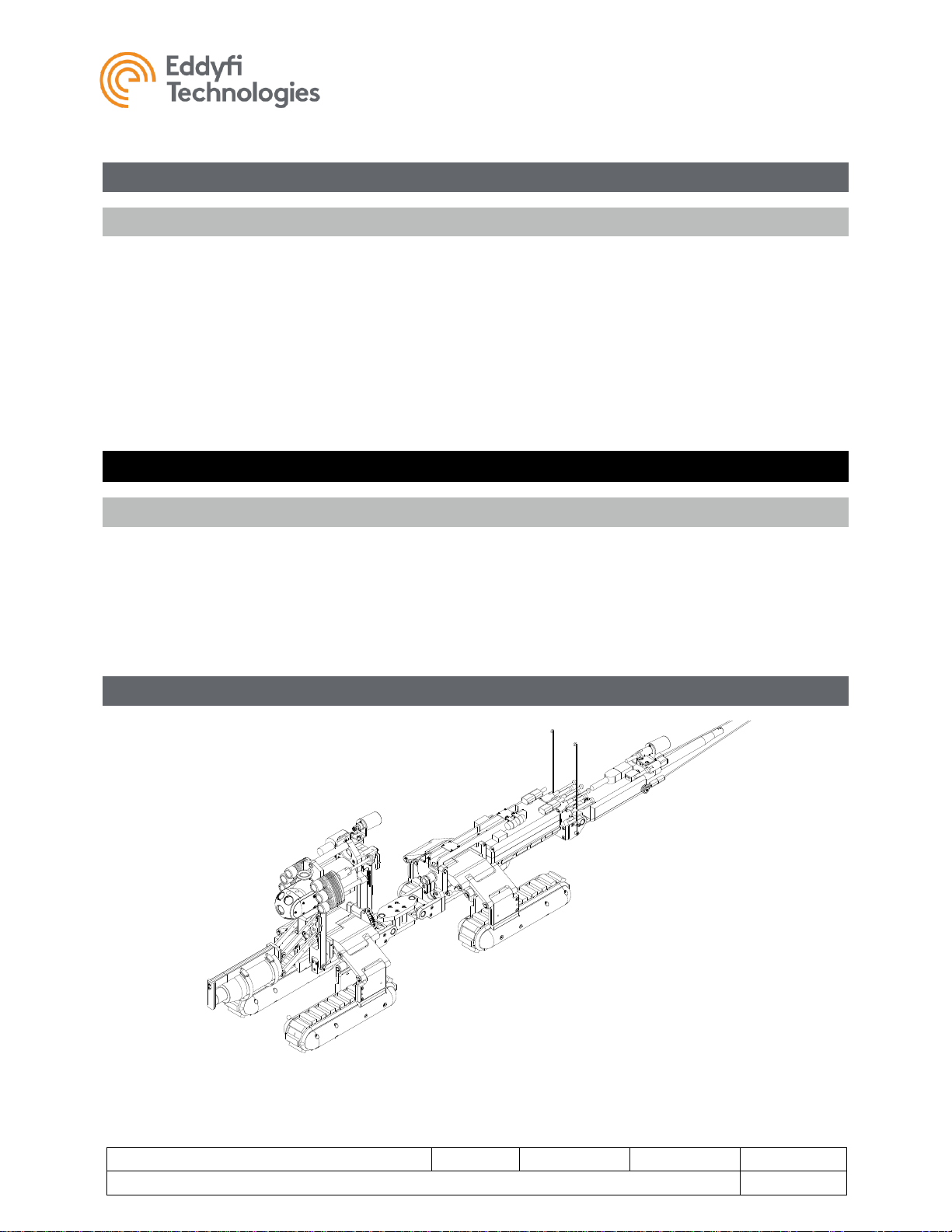
Parallel Vehicle Configuration
FIGURE 4: VT300 FOUR-TRACK CHASSIS
Versatrax 300™
Document: UMBH008532.docm
Revision: A07
Created by: KJB
Date: 26 Sep 2019
3047763-A07
Source Location: C:\ePDM\ISLEng\products\bh-vt300series4-trackchassis\manuals\UMBH008532.docm
Page 17 of 67
Versatrax 300 User Manual
For IBA 5954
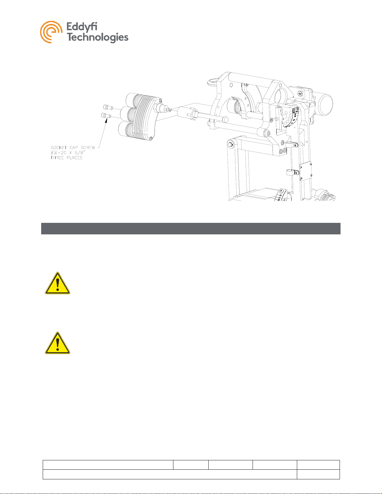
Minitrac™ Installation & Removal
1. The chassis must be in the flat configuration for installation of the tracks.
2. Use the track installation stand provided with the vehicle to hold the chassis while installing the
tracks. Place the jack blocks onto the stand and set the chassis on top. The tapered end of the
stand is at the back of the vehicle.
3. Place the tracks in position around the vehicle.
4. Place the 2x4 spacing blocks under the tracks if you are not using the track extension brackets.
5. Install the outside flanges first using ¼-20 x 5/8in socket cap screws. Leave the screws slightly
loose until the inside bracket bolts are installed (step 7).
6. Plug in all four connector whips.
7. Bolt on the inside brackets using ¼-20 x 1¼in socket cap screws. The inside bolts may be difficult
to align. You may need to jiggle or lift up on the chassis to find the bolt alignment.
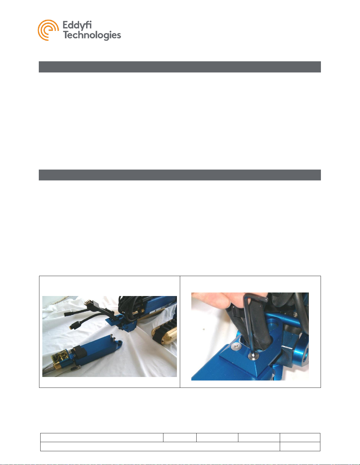
Tether Hook-Up
The photo sequence below shows the procedure for hooking up the tether.
1. The bottom flange remains with the tether termination can; the top flange remains with the
vehicle. The harness whips remain installed through the top flange as shown. It is best to keep
the mounting screws with the can.
2. Mount the can onto the back swivel and screw on the top flange. Make sure top and bottom
screws are tightened.
3. Plug in the connectors, including the Crystal Cam® connector. Make sure connectors are seated
all the way.
4. Install the rear camera bracket
5. Check that the tow cable is securely attached to the termination can.
1
2
Versatrax 300™
Document: UMBH008532.docm
Revision: A07
Created by: KJB
Date: 26 Sep 2019
3047763-A07
Source Location: C:\ePDM\ISLEng\products\bh-vt300series4-trackchassis\manuals\UMBH008532.docm
Page 18 of 67
Versatrax 300 User Manual
For IBA 5954
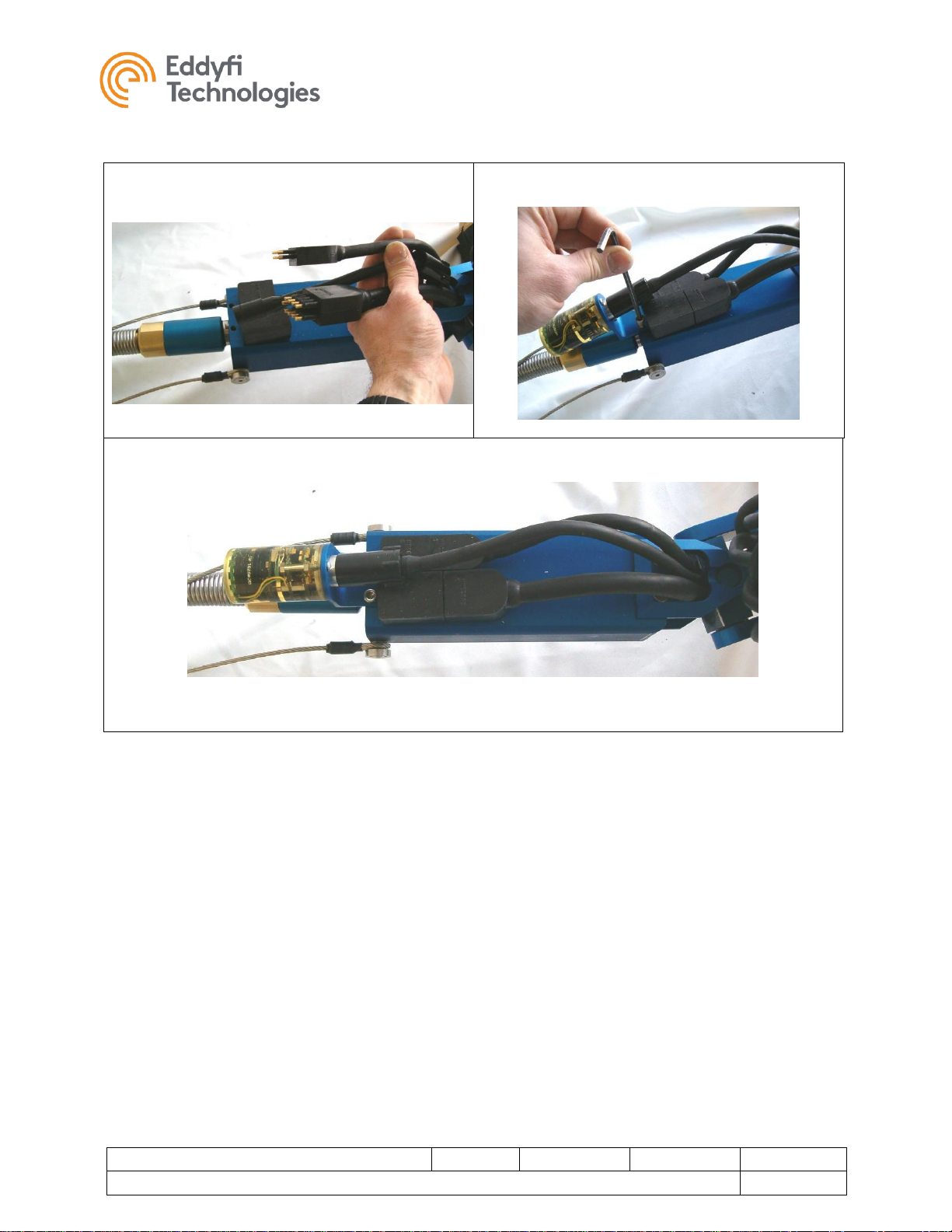
3
4
5
FIGURE 5: TETHER HOOK-UP & REMOVAL

Versatrax 300™
Document: UMBH008532.docm
Revision: A07
Created by: KJB
Date: 26 Sep 2019
3047763-A07
Source Location: C:\ePDM\ISLEng\products\bh-vt300series4-trackchassis\manuals\UMBH008532.docm
Page 19 of 67
Versatrax 300 User Manual
For IBA 5954
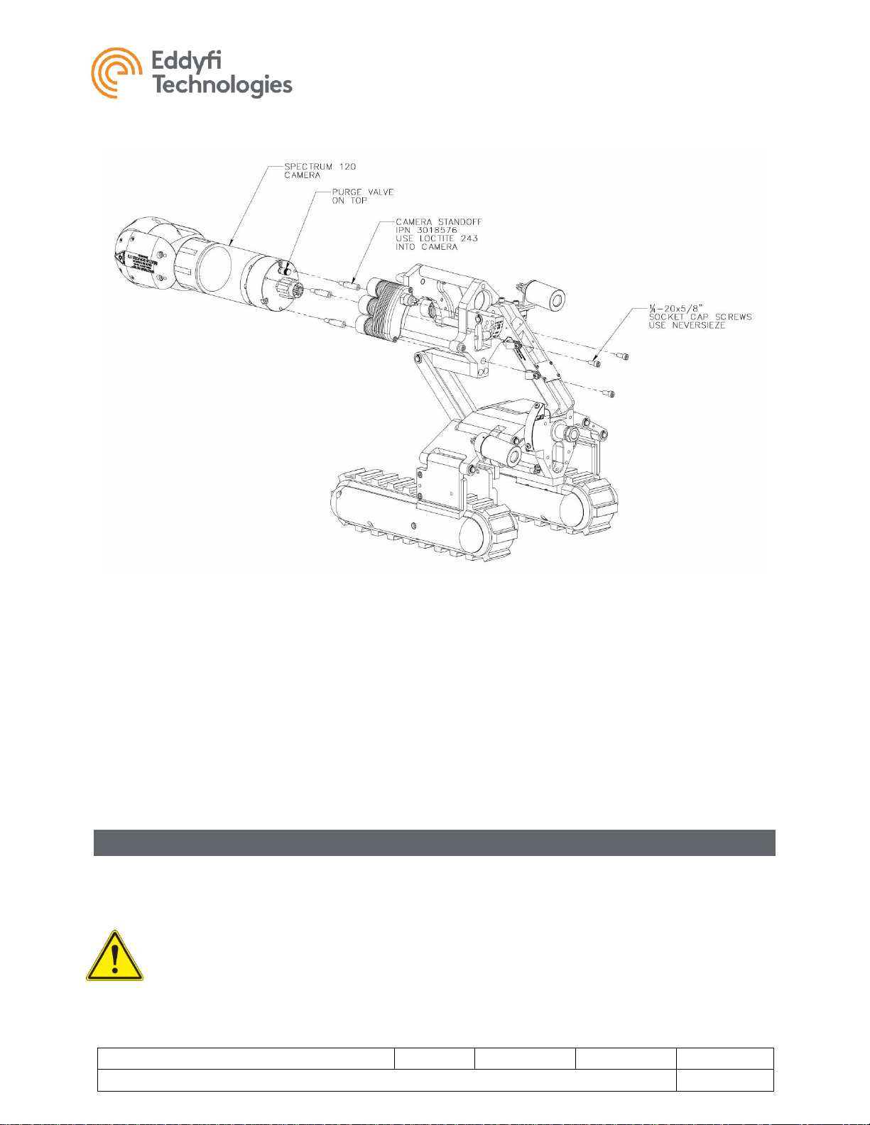
Camera Installation
FIGURE 6: PREFERRED RAISE POSITION FOR CAMERA INSTALLATION
1. Adjust the Camera Raise Mechanism to the position shown in Figure 6. This will enable access to
the camera installation screws.
FIGURE 7: CAMERA MOUNTING HOLES
2. The brass valve indicates the top of the camera, as illustrated in Figure 7. Mount the camera as
shown with the valve on top.
Versatrax 300™
Document: UMBH008532.docm
Revision: A07
Created by: KJB
Date: 26 Sep 2019
3047763-A07
Source Location: C:\ePDM\ISLEng\products\bh-vt300series4-trackchassis\manuals\UMBH008532.docm
Page 20 of 67
Versatrax 300 User Manual
For IBA 5954
FIGURE 8: MOUNTING THE CAMERA
3. Ensure the camera standoffs (IPN 3018576) are installed onto the back of the SP120™ camera.
4. Slide the camera into position from the front of the light mount.
5. Install the connector while the camera is part way in. Ensure that there is enough Silicone grease
on the connector and the female mate (in the pin holes). Push the whip connector onto the
camera all the way. Screw the locking collar onto the bulkhead connector. Finger tight is good.
6. Move the camera into position against the mounting plate. Clear the connector into the square
opening. Using three ¼-20 x 7/8in screws, fasten the camera to the rear plate. Use a 9/64in Ball
end Allen key. Do not over tighten screws.
Auxiliary Light Installation
Auxiliary lights mount onto the back of the front face plate using ¼-20 x 5/8in socket cap bolts. The two
light assemblies are identical and can be swapped from side to side. Plug the light connector all the way
in and install the locking collar – finger tight only.
Warning: Cap unused light whips with dummy plugs. Open whips may short out the light driver
circuit.
Versatrax 300™
Document: UMBH008532.docm
Revision: A07
Created by: KJB
Date: 26 Sep 2019
3047763-A07
Source Location: C:\ePDM\ISLEng\products\bh-vt300series4-trackchassis\manuals\UMBH008532.docm
Page 21 of 67
Versatrax 300 User Manual
For IBA 5954
FIGURE 9: LIGHT INSTALLATION & ADJUSTMENT
Rear Camera Installation
The Versatrax 300™ system can accept one auxiliary 72V Crystal Cam® camera, which is designated as
the rear facing camera for tether observation. As illustrated below, the mounting bracket is located on the
back of the tether termination can.
Warning: The plug-in whip is supplied with 48 VDC. This whip must be capped with a dummy
plug whenever the Crystal Cam® is removed. Electric shock or system damage may otherwise
result. Never operate the system with this connector open.
Warning: The Versatrax Crystal Cam is different from a standard Crystal Cam. It uses a higher
voltage and different connector than the standard Crystal Cam (eight and six-pin, respectively).
You cannot use a standard Crystal Cam® with the Versatrax system. Attempts to install the
standard Crystal Cam® will destroy the camera.
Installation:
1. Remove the cable clamp holding the camera whip.
2. Install the camera bracket as shown using two #10-24 x ½in pan head screws.
3. Install the camera using two #6-32 x ¾in pan head screws. Note the camera orientation marked
“TOP” seen on the label inside the epoxy.
4. Apply a small amount of silicone grease to the camera connector pins.
5. Secure the locking collar after plugging in the camera.
 Loading...