

Eddyfi Technologies Inuktun Versatrax 150 Analog User Manual

2569 Kenworth Road, Suite C
Nanaimo, BC, V9T 3M4
CANADA
+1.250.729.8080
info@eddyfitechnologies.com
www.eddyfitechnologies.com

Versatrax 150™ Analog
Document: UMAI000172-A02.docm
Revision: B02
Created by: PV
Date: 26 Sep 2019
3022922-B02
Source Location: C:\ePDM\ISLEng\products\ai-versatrax150\manuals\UMAI000172-A02.docm
Page 2 of 40
User Manual
Table of Contents
Table of Contents .......................................................................................................................................... 2
About This Manual ........................................................................................................................................ 5
Description and Specifications ...................................................................................................................... 5
Specifications ............................................................................................................................................ 6
Safety ............................................................................................................................................................ 6
System Setup ................................................................................................................................................ 7
Working Environment ............................................................................................................................... 7
Controller ............................................................................................................................................... 7
Tether and Wiring Harnesses ................................................................................................................ 7
Vehicle ................................................................................................................................................... 7
Typical Installation .................................................................................................................................... 8
Vehicle Handling Equipment .................................................................................................................. 8
Personnel Requirements .......................................................................................................................... 8
Power Requirements ................................................................................................................................ 9
Video Hook-Up........................................................................................................................................ 10
Winch Installation .................................................................................................................................... 10
Avoiding Tether Damage ........................................................................................................................ 10
Vehicle Cable Connections ..................................................................................................................... 10
Auxiliary Device ...................................................................................................................................... 11
Camera Installation ................................................................................................................................. 12
101 Auxiliary Lights Installation .............................................................................................................. 14
Bumper Rods .......................................................................................................................................... 15
Minitrac™ Installation and Removal ....................................................................................................... 16
Parallel Configurations 12 inch – 36 inch – Flat ..................................................................................... 19
Track Extensions .................................................................................................................................... 20
Camera Height Extension ....................................................................................................................... 21

Versatrax 150™ Analog
Document: UMAI000172-A02.docm
Revision: B02
Created by: PV
Date: 26 Sep 2019
3022922-B02
Source Location: C:\ePDM\ISLEng\products\ai-versatrax150\manuals\UMAI000172-A02.docm
Page 3 of 40
User Manual
Motorized Camera Raise ........................................................................................................................ 22
Inline Configuration (6-8-10-12) .............................................................................................................. 23
Installing the Tracks ............................................................................................................................. 23
Installing The Spectrum 90™ Camera ................................................................................................. 24
Camera Height / Guide Wheel Adjustment .......................................................................................... 25
Rear Camera Installation ........................................................................................................................ 26
Installation ............................................................................................................................................ 27
System Operation ....................................................................................................................................... 27
Personnel Safety .................................................................................................................................... 27
Personal Safety Equipment ................................................................................................................. 27
Operational Safety .................................................................................................................................. 28
Equipment Safety ................................................................................................................................. 28
Communication ....................................................................................................................................... 28
Tether Handling ...................................................................................................................................... 28
Connector Handling ................................................................................................................................ 29
Power Up / Power Down ......................................................................................................................... 30
Pre-Operations Check ............................................................................................................................ 30
Post-Operations Check ........................................................................................................................... 31
Vehicle Deployment ................................................................................................................................ 31
Vehicle Recovery .................................................................................................................................... 32
Dealing with Obstacles ........................................................................................................................... 32
Sonde Locating Device ........................................................................................................................... 33
Inspection Guidelines ............................................................................................................................. 33
Vehicle Problems .................................................................................................................................... 34
Vehicle Recovery .................................................................................................................................... 35
Maintenance ................................................................................................................................................ 35
Fuse Replacement .................................................................................................................................. 35
Front Panel Fuses .................................................................................................................................. 35

Versatrax 150™ Analog
Document: UMAI000172-A02.docm
Revision: B02
Created by: PV
Date: 26 Sep 2019
3022922-B02
Source Location: C:\ePDM\ISLEng\products\ai-versatrax150\manuals\UMAI000172-A02.docm
Page 4 of 40
User Manual
Internal Fuses (Board Mount) ................................................................................................................. 36
Changing a Bulb (101 Lights) ................................................................................................................. 37
Tether Re-termination ............................................................................................................................. 37
Parts and Repairs ....................................................................................................................................... 38
Ordering Parts/Customer Service ........................................................................................................... 38
Warranty Repairs .................................................................................................................................... 38
Factory Returns to Canada ..................................................................................................................... 39
Product/System Drawing Package Availability ....................................................................................... 39
Limited Warranty Policy .............................................................................................................................. 40

Versatrax 150™ Analog
Document: UMAI000172-A02.docm
Revision: B02
Created by: PV
Date: 26 Sep 2019
3022922-B02
Source Location: C:\ePDM\ISLEng\products\ai-versatrax150\manuals\UMAI000172-A02.docm
Page 5 of 40
User Manual
About This Manual
This manual has been prepared to assist you in the operation and maintenance of your Eddyfi
Technologies Inuktun equipment. Correct and prudent operation rests with the operator who must
thoroughly understand the operation, maintenance, service and job requirements. The specifications and
information in this manual are current at the time of printing.
This product is continually being updated and improved. Therefore, this manual is meant to explain and
define the functionality of the product. Furthermore, schematics or pictorials and detailed functionality
may differ slightly from what is described in this manual.
Eddyfi Technologies reserves the right to change and/or amend these specifications at any time without
notice. Customers will be notified of any changes to their equipment.
Information in this manual does not necessarily replace specific regulations, codes, standards, or
requirements of others such as government regulations.
This manual copyright © 2019 by Inuktun Services Ltd. All rights reserved.
Description and Specifications
The Inuktun Versatrax 150™ Analog pipe inspection system is a Minitrac™ based vehicle used for
navigating pipelines ranging from 6 inch to 36-inch diameters (camera centered). The track mechanism is
further adjustable beyond 36 inches to very large diameters.
The system is made with the hazards and demands of pipe inspection in mind. The rugged dual tractors
permit pipe penetration up to 1500 feet. A minimized vehicle profile provides maximum clearance for
passage of service intrusions in the pipe.
All Versatrax hardware can be used underwater and in dirty, muddy conditions. The rugged design
ensures a long service life and helps protect the vehicle from damage during normal use.
Typical applications include inspection of:
• Sewer and storm drains
• Hydroelectric pipe and infrastructure
• Steam headers
• Tanks and pressure vessels
• Oil & gas refineries and pipelines
• Pulp and paper mills

Versatrax 150™ Analog
Document: UMAI000172-A02.docm
Revision: B02
Created by: PV
Date: 26 Sep 2019
3022922-B02
Source Location: C:\ePDM\ISLEng\products\ai-versatrax150\manuals\UMAI000172-A02.docm
Page 6 of 40
User Manual
Specifications
Pipe Size Range
Minimum: 12in/ 300mm Maximum: Flat
Camera Centered: 16in-24in/ 400mm – 610mm
Operating Temperature
0 º – 50 ºC (32 º - 122 ºF) Dependant on operating
conditions. Ask your sales expert for more information
Storage Temperature
-20 º – 60 ºC ( -4 º– 140 ºF)
Depth Rating
VT150 Chassis, Tracks, Cameras and Lights: 60 m
(200 ft)
Vehicle Weight
40 kg (88 lb) Weight may vary depending on
configuration
Power Input
Switchable between 120VAC/ 60Hz and 220VAC/
50/60Hz
Safety
• All personnel operating or maintaining this equipment must read and understand the operations
and maintenance manual prior to system operation.
• All personnel operating or maintaining this equipment must be competently trained.
• Appropriate personal protective equipment (PPE) must be worn while operating and maintaining
the equipment.
• Observe all traffic safety requirements in effect in your municipality.
• Wear steel toed boots when working with the VT150 Vehicle.
• Wear protective gloves while deploying the vehicle.
• Never stand on the tether. The vehicle and winch are strong enough to pull it out from under you
and cause you to fall. Standing on the tether also increases wear and tear.
• The tether carries 120 VAC for the main lights. Always keep unused light whips capped. Follow
the guidelines for preventing tether damage. Do not operate with damaged light whips.
• Repair any damaged wires before operating the vehicle. A short circuit may damage the
controller, cameras, or any attached equipment.
• Never drop the vehicle. Although built tough, the vehicle is heavy, increasing the chance of
structural damage when dropped.
• Under no circumstances should this equipment be used in a potentially explosive atmosphere.
• If the equipment is powered from a source other than an Eddyfi provided controller, the power
supplied to the product must have reinforced isolation from the mains with no reference to earth
ground.
Caution: Disconnect the power source before servicing the product; otherwise, damage may result.

Versatrax 150™ Analog
Document: UMAI000172-A02.docm
Revision: B02
Created by: PV
Date: 26 Sep 2019
3022922-B02
Source Location: C:\ePDM\ISLEng\products\ai-versatrax150\manuals\UMAI000172-A02.docm
Page 7 of 40
User Manual
• Overhead Lifting / Hoisting: Take care when using cranes or overhead equipment for vehicle
deployment. Watch for overhead cables and take appropriate safety precautions (hard hats,
steel-toed boots, gloves, etc.)
• Heavy Lifting: Use safe lifting practices according to your work-site regulations when handling
the vehicle and its components.
• Pinching Hazard: There is a possibility that a person’s fingers could be drawn into the tracks
should they be activated when the vehicle is being handled. To avoid this hazard do not connect
the tether to the portable controller until the vehicle is configured, placed and ready to use. If the
vehicle is being tested, do not connect the tether until handling of the vehicle is complete. If the
vehicle is permanently installed into a van or trailer and the tether cannot be disconnected, turn
off the power instead.
Safe lifting recommendations:
• Two people are recommended to lift and carry the tether container because of its awkward size
and weight.
• Know your own strengths and limits. Assess whether the object is too heavy for you before
attempting to lift.
• Lift with your knees – not your back.
System Setup
Working Environment
Controller
The controller is to be used in a dry, covered environment only. The controller connectors are not
waterproof. Keep all cords and cables away from water.
Recommended controller operating temperatures are between 0º and 50º Celsius.
Tether and Wiring Harnesses
The tether and vehicle wiring harnesses are depth rated to 200 feet (60m) of water. However, the main
connector may only be exposed to water when it is plugged in. Keep it capped with a dummy plug when
not connected to the vehicle.
The winch is splash resistant only. Refer to the winch manual.
Vehicle
The Minitracs™, vehicle wiring harnesses and chassis are designed to work underwater up to 200 feet.
The tracks are tolerant toward sandy and muddy conditions, although this decreases seal life. The vehicle
may also be operated in dry or dusty environments in the recommended operating temperature range of
0º to 50º C.
Allowable system storage temperatures are between -20º and +60º C.

Versatrax 150™ Analog
Document: UMAI000172-A02.docm
Revision: B02
Created by: PV
Date: 26 Sep 2019
3022922-B02
Source Location: C:\ePDM\ISLEng\products\ai-versatrax150\manuals\UMAI000172-A02.docm
Page 8 of 40
User Manual
Typical Installation
The following describes a typical installation scenario recommended by us.
A typical set up for a pipe inspection system is based on a covered two-ton or larger box truck. The truck
carries the power source (generator) and houses the power supply and control system in a dry, covered
environment. The computer/ control console and recording equipment are placed in an office-like room
built into the truck. The rear wall of the truck should open completely. The winch, crane and other
equipment can be mounted at the back of the truck box near the door for easy deployment. The truck
should also contain the maintenance shop, ample bench space for maintaining and configuring the
vehicle and system wash down equipment.
The vehicle should be operated by a crew of at least two. Most importantly, a person should be available
to tend the tether at all times. This person may also play a role in vehicle inspection and deployment. A
second person drives the vehicle and operates the recording equipment.
The operations crew should be able to communicate quickly with each other to allow fast response in
case of an emergency such as a tether hang up. It is recommended that a signal system be set up so
that the operators may work efficiently and safely as a team. It is always advantageous for both
operators to be aware of full system status.
Vehicle Handling Equipment
Because the vehicle is heavy, some handling equipment is recommended with the system installation.
• The first of these is a swinging overhead boom for vehicle deployment which must hold the
payout sheave axle at least 9 feet above ground level. The capacity of the arm needs to be at
least ½-tonne at full extension – enough for full vehicle weight plus full winch power.
• The payout sheave diameter should be at least 10-inch diameter to help prevent tether fatigue.
• An electric cable hoisting winch with at least ½-tonne load capacity is necessary to raise and
lower the vehicle. The cable on this hoist needs to be long enough for the deepest expected
deployment.
We recommend a dedicated work bench for vehicle configuration and maintenance. Ideally this is at least
30 inches by 60 inches and is accessible from both sides. The lower portions of the bench may be
equipped with racks or drawers where tools, spare parts and fasteners are kept.
Personnel Requirements
A typical pipe inspection van operation usually requires two people for operations.
Console Operator – This person is responsible for driving the vehicle, watching the pipe and making
notes and comments about location and pipe situation. It is also the operator’s responsibility to assess
whether a pipe is in condition for safe passage of the vehicle or risk getting stuck. The operator may also
assist in general site setup (cones/ warning signs), vehicle maintenance and configuration.
Deployment / Tether Handler / Field Maintenance – This person has several tasks:
Versatrax 150™ Analog
Document: UMAI000172-A02.docm
Revision: B02
Created by: PV
Date: 26 Sep 2019
3022922-B02
Source Location: C:\ePDM\ISLEng\products\ai-versatrax150\manuals\UMAI000172-A02.docm
Page 9 of 40
User Manual
• Configure the vehicle for the current pipe
• Lower the vehicle into and out of the manhole
• Watch the tether as the vehicle enters and exits the pipe
• Operate the winch and wind the tether during recovery.
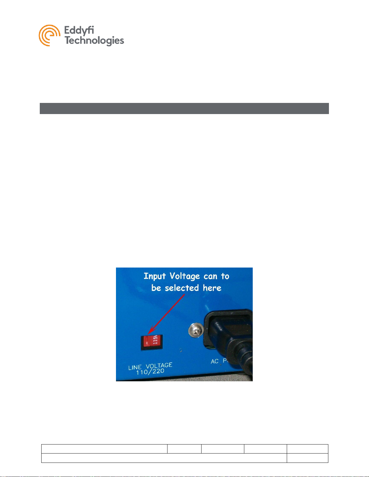
Power Requirements
Line Voltage – When installing the system in a new location always check the line voltage selection
switch located next to the AC power cord on the controller. This switch may be set for 110VAC or
220VAC power input and must match the line voltage of the power source. Incorrectly setting this switch
will damage the controller.
If your system includes a powered cable winch refer to the winch manual for instructions on setting its
input voltage. An incorrect voltage at the winch will damage the motor controller.
Power Requirement – The following figures are for a 1500-foot system and take component efficiency
and tether power loss into account.
Vehicle and Controller = 800W; Winch = 1000W, Total system = 1800W peak load.
With no winch the system can operate comfortably on a 1000W supply or inverter. With a full system we
recommend a minimum of 2000W supply or inverter. Remember to account for the power used by your
monitors and video recorders.
The Versatrax™ controller is designed to support our tracks, cameras, and lights. Powering other
devices or equipment off the Versatrax controller is not recommended.
FIGURE 1: LINE VOLTAGE SELECT SWITCH

Versatrax 150™ Analog
Document: UMAI000172-A02.docm
Revision: B02
Created by: PV
Date: 26 Sep 2019
3022922-B02
Source Location: C:\ePDM\ISLEng\products\ai-versatrax150\manuals\UMAI000172-A02.docm
Page 10 of 40
User Manual
Video Hook-Up
The external video connectors on your Versatrax system use RCA style video jacks similar to most
monitors and video equipment. An RCA style video cable has been supplied with the controller. Some
industrial monitors may use a BNC style video jack. An RCA to BNC adapter has been supplied for this
purpose.
Video from your Versatrax™ controller may be connected directly to the video input of a television, VCR,
or other recording device. Please refer to your television or recording device owner’s manual.
Winch Installation
If your system includes an AC powered winch, refer to the winch manual for installation instructions.
Avoiding Tether Damage
The tether is the most vulnerable part of the Versatrax system. Tether damage is a serious matter but is
generally avoidable through proper handling. Re-termination means lost time, and tether replacement is
a significant cost. As a precaution we recommend that anyone using or handling the Versatrax system
read and understand this manual before working with the system.
Vehicle Cable Connections
It is very important to properly connect the tether and strain relief to the vehicle. Improper connection
may result in costly tether damage. See the figures below.
1. The tow cable must be securely attached to the harness block.
2. The other end of the tow cable clips to the Kellems Grip strain relief. Ensure the Kellems Grip is
adjusted properly to allow some tether slack as shown.
3. Plug the connector all the way in. It is important for the longevity of the connector that it be kept
free of dirt, have good o-rings and be mated carefully.
4. It is important to adjust the Kellems grip to allow slack in the tether connection, no matter what
angle the tether approaches the vehicle.
5. Tether connection to the parallel and in-line vehicles are identical.
6. When the tether is not plugged in, it should be capped to prevent dirt and moisture from entering
the pins.

Versatrax 150™ Analog
Document: UMAI000172-A02.docm
Revision: B02
Created by: PV
Date: 26 Sep 2019
3022922-B02
Source Location: C:\ePDM\ISLEng\products\ai-versatrax150\manuals\UMAI000172-A02.docm
Page 11 of 40
User Manual
FIGURE 2: TETHER AND TOW CABLE CONNECTION
FIGURE 3: KELLEMS GRIP HOOK-UP
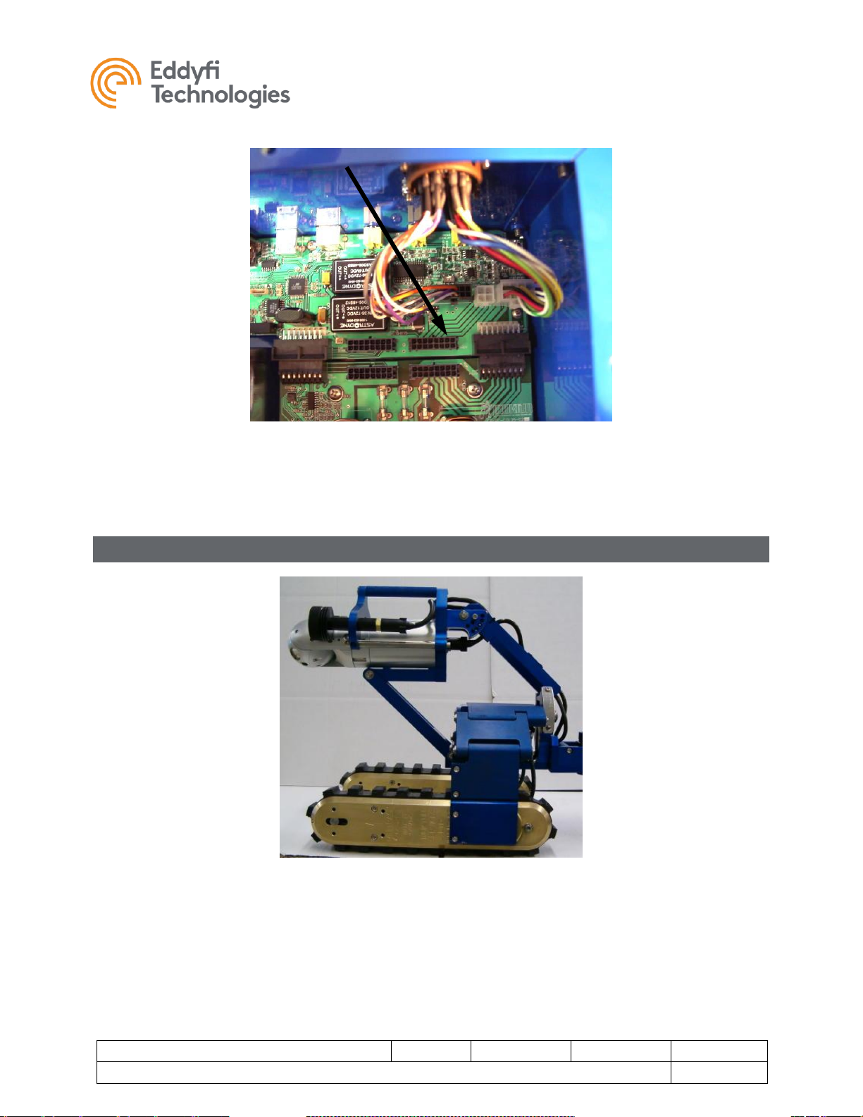
Auxiliary Device
There is provision in the Versatrax™ system to allow add-on devices such as a rear facing camera,
sonar, or other vehicle electronics. A twisted pair in the tether is reserved for telemetry from this device.
The controller must be configured by setting a dip switch on the main control PCB (see Figure 4 below).
The standard configuration is to use this twisted pair for the rear camera.
• If vehicle has a second camera, set the auxiliary dip switch to the position marked “rear video”.
This is the default position shipped from the factory. The switch must be in this position in order
to receive video from a secondary camera.
• If the spare conductors are to be used by other devices, such as sonar or on-board sensors, the
switch must be set to the position marked “spare cond.” This will route the signals to the
“Desktop Controller” connector on the controller.
Versatrax 150™ Analog
Document: UMAI000172-A02.docm
Revision: B02
Created by: PV
Date: 26 Sep 2019
3022922-B02
Source Location: C:\ePDM\ISLEng\products\ai-versatrax150\manuals\UMAI000172-A02.docm
Page 12 of 40
User Manual
FIGURE 4: AUXILIARY DIP SWITCH
Camera Installation
FIGURE 5: PREFERRED RAISE POSITION FOR CAMERA INSTALLATION
1. Adjust the Camera Raise Mechanism to the position shown in Figure 5. This will allow access to
the camera mounting screws.
 Loading...