


Eddyfi Robotics Inc.
2569 Kenworth Road, Suite C
Nanaimo, BC, V9T 3M4
CANADA
+1.250.729.8080
info@eddyfitechnologies.com
www.eddyfitechnologies.com
INUKTUN VERSATRAX 150™

Versatrax 150™
Document: UMDW014058.docm
Revision: A03
Created by: KW
Date: 10 Oct 2019
3075415-A03
Source Location: C:\ePDM\ISLEng\products\dw-versatrax150mkii\manuals\UMDW014058.docm
Page 2 of 57
User Manual
Table of Contents
About This Manual ........................................................................................................................................ 5
System Description ....................................................................................................................................... 5
Specifications ............................................................................................................................................ 6
Certification ............................................................................................................................................... 7
Safety ........................................................................................................................................................ 7
System Setup ................................................................................................................................................ 9
Working Environment ............................................................................................................................... 9
System Power ........................................................................................................................................... 9
Power Requirements ............................................................................................................................. 9
Set the Line Voltage............................................................................................................................. 10
Generators / Inverters .......................................................................................................................... 10
Connections ............................................................................................................................................ 11
Pre-Configured Control Rack ............................................................................................................... 11
Control System Connections – SD Video ............................................................................................ 12
Control System Connections – HD Video ............................................................................................ 12
Fiber Optic Tether ................................................................................................................................ 13
Client Configured Rack ........................................................................................................................ 14
Vehicle and Tether ............................................................................................................................... 15
Winch Installation .................................................................................................................................... 16
Portable Reel Setup ................................................................................................................................ 16
Tether Handling ...................................................................................................................................... 17
Connector Handling ................................................................................................................................ 17
SubConn Connector: Lubrication and Cleaning .................................................................................. 18
Impulse Connector: Lubrication and Cleaning ..................................................................................... 18
System Installation .................................................................................................................................. 18
Vehicle Layout ..................................................................................................................................... 18
Vehicle Handling .................................................................................................................................. 19
Communication .................................................................................................................................... 19
Personnel Requirement ....................................................................................................................... 19

Versatrax 150™
Document: UMDW014058.docm
Revision: A03
Created by: KW
Date: 10 Oct 2019
3075415-A03
Source Location: C:\ePDM\ISLEng\products\dw-versatrax150mkii\manuals\UMDW014058.docm
Page 3 of 57
User Manual
Vehicle Configuration .................................................................................................................................. 20
Parallel Vehicle ....................................................................................................................................... 20
Chassis Pipe Sizing ............................................................................................................................. 20
Powered Camera Raise ....................................................................................................................... 21
Minimum Bend Sizes ........................................................................................................................... 22
Spectrum 90™ Installation ................................................................................................................... 23
Spectrum 120HD™ Installation ........................................................................................................... 25
Spectrum 120™ Bumper Bars ............................................................................................................. 25
Light Installation ................................................................................................................................... 26
Minitrac™ Installation........................................................................................................................... 28
Track Height Extensions ...................................................................................................................... 31
Spectrum™ Camera Extension ........................................................................................................... 32
Rear Camera Installation ..................................................................................................................... 33
Advanced Accessories......................................................................................................................... 34
Minitrac™ Length Extensions .............................................................................................................. 34
Active Track Chassis Articulation ........................................................................................................ 34
Sonde ................................................................................................................................................... 35
Fiber Optic Tether ................................................................................................................................ 36
Laser Scanner Mount........................................................................................................................... 37
Odometry Module ................................................................................................................................ 38
Inline Vehicle........................................................................................................................................... 40
Minitrac™ Installation........................................................................................................................... 40
Spectrum 90™ Installation ................................................................................................................... 41
Guide Wheel Adjustment ..................................................................................................................... 41
Camera Height / Skid Adjustment ........................................................................................................ 43
Rear Camera Installation ..................................................................................................................... 44
Operation..................................................................................................................................................... 45
Pre-Operations Check ............................................................................................................................ 45
Post-Operations Check ........................................................................................................................... 46
ICON™ & ICON™ RPT .......................................................................................................................... 46
Power-Up Sequence ............................................................................................................................... 46
Ground Fault Detection & Alarms ........................................................................................................... 47

Versatrax 150™
Document: UMDW014058.docm
Revision: A03
Created by: KW
Date: 10 Oct 2019
3075415-A03
Source Location: C:\ePDM\ISLEng\products\dw-versatrax150mkii\manuals\UMDW014058.docm
Page 4 of 57
User Manual
Dealing With Obstacles .......................................................................................................................... 48
Inspection Guidelines ............................................................................................................................. 48
Powered Winch Operation ...................................................................................................................... 48
Vehicle Recovery .................................................................................................................................... 49
Emergency Recovery........................................................................................................................... 50
Troubleshooting .......................................................................................................................................... 50
Camera Control Problems ...................................................................................................................... 50
Video Problems....................................................................................................................................... 51
Vehicle Problems .................................................................................................................................... 51
Winch Problems ...................................................................................................................................... 52
Maintenance ................................................................................................................................................ 53
Rinsing and Cleaning .............................................................................................................................. 53
Fuse Replacement .................................................................................................................................. 53
Minitrac™ Maintenance .......................................................................................................................... 53
Camera Maintenance ............................................................................................................................. 53
Tether Re-termination ............................................................................................................................. 54
Parts and Repairs ....................................................................................................................................... 54
Ordering Parts/Customer Service ........................................................................................................... 54
Warranty Repairs .................................................................................................................................... 55
Factory Returns to Canada ..................................................................................................................... 55
Product/System Drawing Package Availability ....................................................................................... 55
Limited Warranty Policy .............................................................................................................................. 56

Versatrax 150™
Document: UMDW014058.docm
Revision: A03
Created by: KW
Date: 10 Oct 2019
3075415-A03
Source Location: C:\ePDM\ISLEng\products\dw-versatrax150mkii\manuals\UMDW014058.docm
Page 5 of 57
User Manual
About This Manual
This manual has been prepared to assist you in the operation and maintenance of your Eddyfi
Technologies’ Inuktun equipment. Correct and prudent operation rests with the operator who must
thoroughly understand the operation, maintenance, service and job requirements. The specifications and
information in this manual are current at the time of printing.
This product is continually being updated and improved. Therefore, this manual endeavors to explain and
define the functionality of the product. Furthermore, schematics or pictorials and detailed functionality
may differ slightly from what is described in this manual.
Eddyfi Technologies reserves the right to change and/or amend these specifications at any time without
notice.
Information in this manual does not necessarily replace specific regulations, codes, standards, or
requirements of others such as government regulations.
This manual is copyright © 2019 by Eddyfi Robotics Inc. All rights reserved.
System Description
The Inuktun Versatrax 150™ is a system of pipeline video inspection vehicles based on the Minitrac™ 8000
crawler. Using In-Line and Parallel chassis’, the system navigates pipelines from 150 – 900 mm (6 – 36 in)
internal diameter with the camera centered, with an infinite size range with the camera non-centered. As
such, the parallel chassis is often used for inspections over industrial floor space, pools and other harsh
environments as well.
The inspection system has been manufactured with the hazards and demands of pipe inspection in mind.
The rugged dual tracks permit pipe penetration up to 1,000 m (3,300 ft), with extended range possible using
an optional fiber optic tether.
All Versatrax hardware can be used dry, underwater, or in dirty, muddy conditions. The rugged design
ensures a long service life and helps protect the vehicle from damage during normal use.
Typical applications include inspection of:
• Sewer and storm drains
• Hydroelectric pipe and infrastructure
• Steam headers
• Tanks and pressure vessels
• Oil and gas refineries and pipelines
• Pulp and paper mills

Versatrax 150™
Document: UMDW014058.docm
Revision: A03
Created by: KW
Date: 10 Oct 2019
3075415-A03
Source Location: C:\ePDM\ISLEng\products\dw-versatrax150mkii\manuals\UMDW014058.docm
Page 6 of 57
User Manual
Specifications
Min Vehicle
Dimensions
Parallel
Ø300 x 1050 mm (Ø12 x 41.5 in)
Inline
Ø150 x 2000 mm (Ø6 x 79 in)
Vehicle
Weight1
Parallel
45 kg (100 lb)
Inline
45 kg (100 lb)
Depth Rating
60 m (200 ft)
Pipe Size
Range2
Parallel
Camera Centered
305 – 610 mm (12 – 24 in)
Camera Centered with Track Extension
460 – 700 mm (18 – 28 in)
Camera not Centered
610 mm (24 in) – Flat
Inline
Camera Centered with Skids
150 – 305 mm (6 – 12 in)
Maximum Tether Length3
1,000 m (3,300 ft)
Tracks
2x Minitracs™ 8000
Camera
Front
Standard
Spectrum 90™
Option
Spectrum 120HD™
Rear
Standard
Sapphire™
Lights
(Parallel Only)
2x 901 Lights
Reel
Standard
Portable tether reel with payout encoder
Option
High capacity powered winch
Parallel Chassis Optional Components
Manual Camera Raise
Weight Kit – 25.5 kg (56 lb)
Track Extension Kit
Camera Extension Kit
Powered Active Track Angle Adjustment
Power Requirements
100 – 240 VAC 50/60Hz, 1.9 – 3.1 kW
Operating Temperature
0 – 50 ºC (32 – 122 ºF)
Storage Temperature
-20° – 60 ºC (-4 –140 ºF)
1
Weights may vary depending on optional components
2
Specified pipe sizes are internal diameters
3
Actual travel distance may be decreased depending on inspection geometry (traction and number of bends)
Versatrax 150™
Document: UMDW014058.docm
Revision: A03
Created by: KW
Date: 10 Oct 2019
3075415-A03
Source Location: C:\ePDM\ISLEng\products\dw-versatrax150mkii\manuals\UMDW014058.docm
Page 7 of 57
User Manual
Certification
The Inuktun Versatrax 150™ system is built in accordance with the Low Voltage Directive 2006/95/EC,
Machinery Directive 2006/42/EC, and Electromagnetic Compatibility Directive 2004/108/EC.
Safety
In order to be able to use this product properly and safely, every user must first read these operating
instructions and observe the safety instructions contained therein. Take care of these operating
instructions and keep them in a place where they can be accessed by everyone. Untrained personnel
should not handle or operate this equipment.
CAUTION: Failure to follow these safety instructions may result in injury or
equipment damage.
This system includes some specific devices that have their own User Manuals. Instructions on those
manuals must be also read before using the system.
WARNING: High Voltage
The tether carries 400 VDC to the rear harness block, and the Minitrac™ whips
carry 400 VDC from the harness block to the tracks. Always Keep the tether
capped when not installed on the vehicle. Follow the guidelines for preventing
tether damage.
400 VDC can cause serious injury or death. Do not operate with a damaged
tether or Minitrac™ whip. Do not operate the system with damaged wires.
Damaged cabling poses a shock hazard. Repair damaged cabling before
operating the vehicle. A short circuit may also damage the controller, cameras, or
any attached equipment.
Disconnect the power source before servicing the product; otherwise, damage or
fatal injury may result.
The power supply is equipped with a ground fault interrupt circuit. Do not cheat or
bypass the ground fault interrupt circuit. Do not power the equipment from a
source other than the Eddyfi Technologies provided power supply.
Versatrax 150™
Document: UMDW014058.docm
Revision: A03
Created by: KW
Date: 10 Oct 2019
3075415-A03
Source Location: C:\ePDM\ISLEng\products\dw-versatrax150mkii\manuals\UMDW014058.docm
Page 8 of 57
User Manual
WARNING: Intense Optical Radiation - The Versatrax 150™ camera lights and
901 auxiliary lights are extremely bright and can cause temporary flash blindness.
Never look directly at the lights, or even from a shallow angle. Use a welding filter
(shade #8 or higher) if inspecting the LEDs.
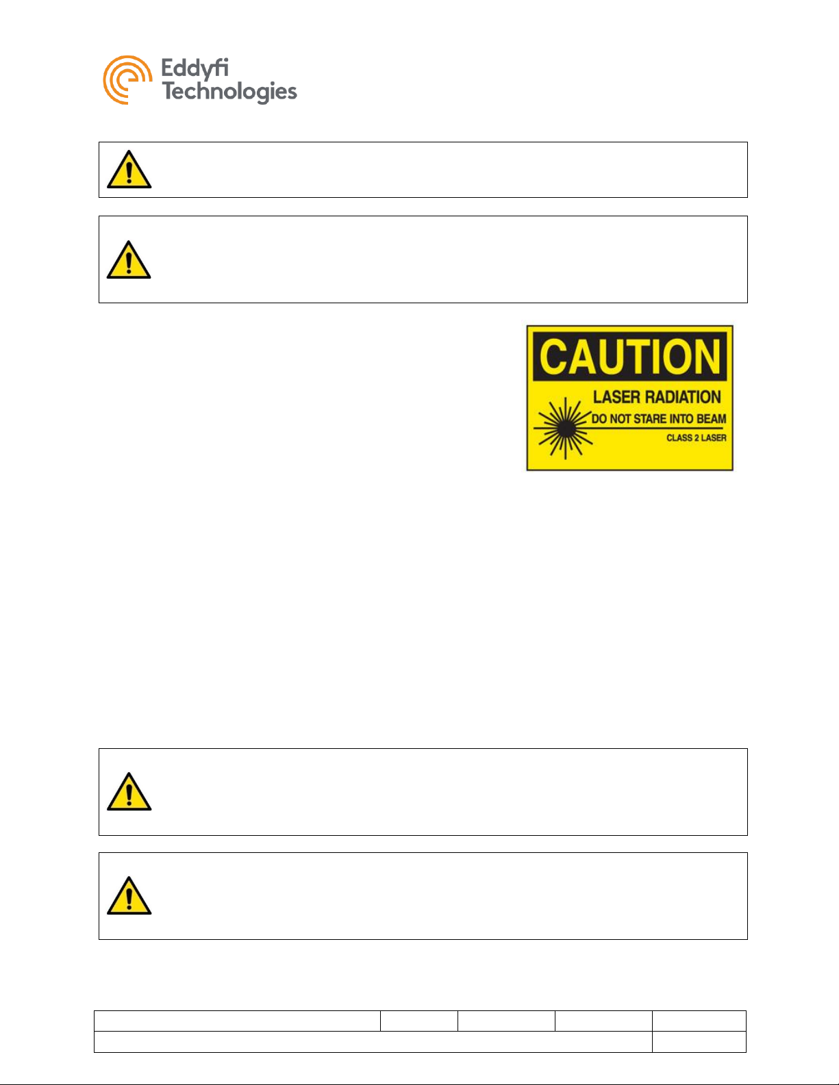
CAUTION: Class II Laser: The Spectrum 90/120™ camera may
be equipped with laser lines. Do not intentionally stare into the
beam. Typically, Class II relies on the blink reflex to limit exposure
to no more than ¼-second. Intentionally staring into the beam can
cause eye injury.
• When performing maintenance or functional checks of the
lasers and camera lights, take precautions to protect
nearby personnel from unintended exposure which could
be temporarily blinding.
• Observe safe lifting and handling practices. Component parts of the Inuktun Versatrax 150™
system are heavier than the recommended lifting load for a single person. Two people are
recommended for lifting the vehicle.
• Never drop the vehicle. Although built tough, the vehicle is heavy and can suffer structural
damage when dropped.
• Prevent impact to the front of the 901 lights, Spectrum 90/120™ camera and Inuktun Sapphire™
cameras as they can suffer damage.
• Eddyfi equipment is used in many varied environments from hot/dry to confined spaces to deep
underwater. Such diverse environmental risks must be addressed by the operators who are
trained to work in such surroundings. As such, the operators are responsible to determine safe
site setup, work procedures and appropriate personal protective equipment (PPE) for setup and
operation of the equipment.
WARNING: Trip Hazard - Never stand on the tether. The vehicle and winch are
strong enough to pull it out from underneath you and cause you to fall. Standing
on the tether may also cause damage to the internal conductors and decrease the
life of the protective jacket.
WARNING: High Temperature - The camera head, 901 lights and harness block
may become extremely hot during operation. Always wear protective gloves when
handling these parts of the vehicle after they have been in use. Allow a cool-down
period before handling without gloves.
WARNING: Spark Hazard - Under no circumstances should this equipment be
used in a potentially explosive atmosphere

Versatrax 150™
Document: UMDW014058.docm
Revision: A03
Created by: KW
Date: 10 Oct 2019
3075415-A03
Source Location: C:\ePDM\ISLEng\products\dw-versatrax150mkii\manuals\UMDW014058.docm
Page 9 of 57
User Manual
WARNING: Mechanical Pinch Hazard – Rotating or moving components can
draw fingers into a pinch position. Do not handle the vehicle while mobile parts are
running, turn off power or disconnect the tether while reconfiguring or maintaining
the vehicle.
System Setup
Working Environment
The control system (interface box, power supply, and Control computer) is to be used in a dry, covered
environment only. These components are not waterproof. Keep all cords and cables away from water.
The tether and vehicle are depth rated to 60 m (200 ft) of water. The tether connector is a wet-mate type
which may be wet when plugged in but cannot be plugged in underwater. Keep the tether connector
capped with a dummy plug when not connected to the vehicle to help keep out dirt. The tracks are
tolerant to sandy and muddy conditions, although this decreases seal life. The vehicle may also be
operated in dry or dusty environments.
The portable reel and winch are splash resistant only. Refer to the reel manual.
To maximize component life and minimize deployment time it is recommended that the vehicle and tether
be cleaned after use and the entire system stored in a dry, dust free, location.
System storage temperatures are between -20 ˚C – 60 ˚C (-4 ˚F – 140 ˚F)
System Power
Power Requirements
The power requirements given below are maximums for a fully configured system with cable reel. For
use with 110 VAC source, a fully configured Versatrax150™ system requires three independent standard
15 A circuits for power, or one 20 A and one 15 A circuits as follows.
Power
Circuit
Control Computer
500W
110 VAC @ 15 A
110 VAC @ 20 A
Monitor
80W
Power Supply / Interface Box
1300W
110 VAC @ 15 A
Powered Winch
1200W
110 VAC @ 15 A
110 VAC @ 15 A
System Total
3080 W
Versatrax 150™
Document: UMDW014058.docm
Revision: A03
Created by: KW
Date: 10 Oct 2019
3075415-A03
Source Location: C:\ePDM\ISLEng\products\dw-versatrax150mkii\manuals\UMDW014058.docm
Page 10 of 57
User Manual
Set the Line Voltage
Before powering on the Versatrax 150™ system, it is important to check that the input voltage settings
are correct - an incorrect voltage setting will damage the system power supply and the winch controller.
When installing the system in a new location always check the line voltage.
• Monitor: Universal - no action required.
• Computer: Universal - no action required.
• Interface Box: Universal - no action required.
• Power Supply: Set the line voltage switch to 115/230VAC and change fuse.
o For 115 VAC use 15 A MDA type fuse.
o For 230 VAC use 10 A MDA type fuse.
• Winch: Jumpers must be set inside the hand-held controller to switch between 115 VAC and
230 VAC. Refer to the winch manual for instructions.
WARNING: Line Voltage Select – Failing to select the proper line voltage on the
power supply and winch will result in equipment damage.
Generators / Inverters
If powering the system from a generator or inverter, refer to that unit’s operating manual for
recommendations on continuous and peak load ratings. These power sources may apply a reduced
output rating based on electrical load and environmental temperature. Remember to include the power
needs of all other connected devices (external monitors, recording devices, lighting, etc.) when selecting
a generator or inverter.
Versatrax 150™
Document: UMDW014058.docm
Revision: A03
Created by: KW
Date: 10 Oct 2019
3075415-A03
Source Location: C:\ePDM\ISLEng\products\dw-versatrax150mkii\manuals\UMDW014058.docm
Page 11 of 57
User Manual
Connections
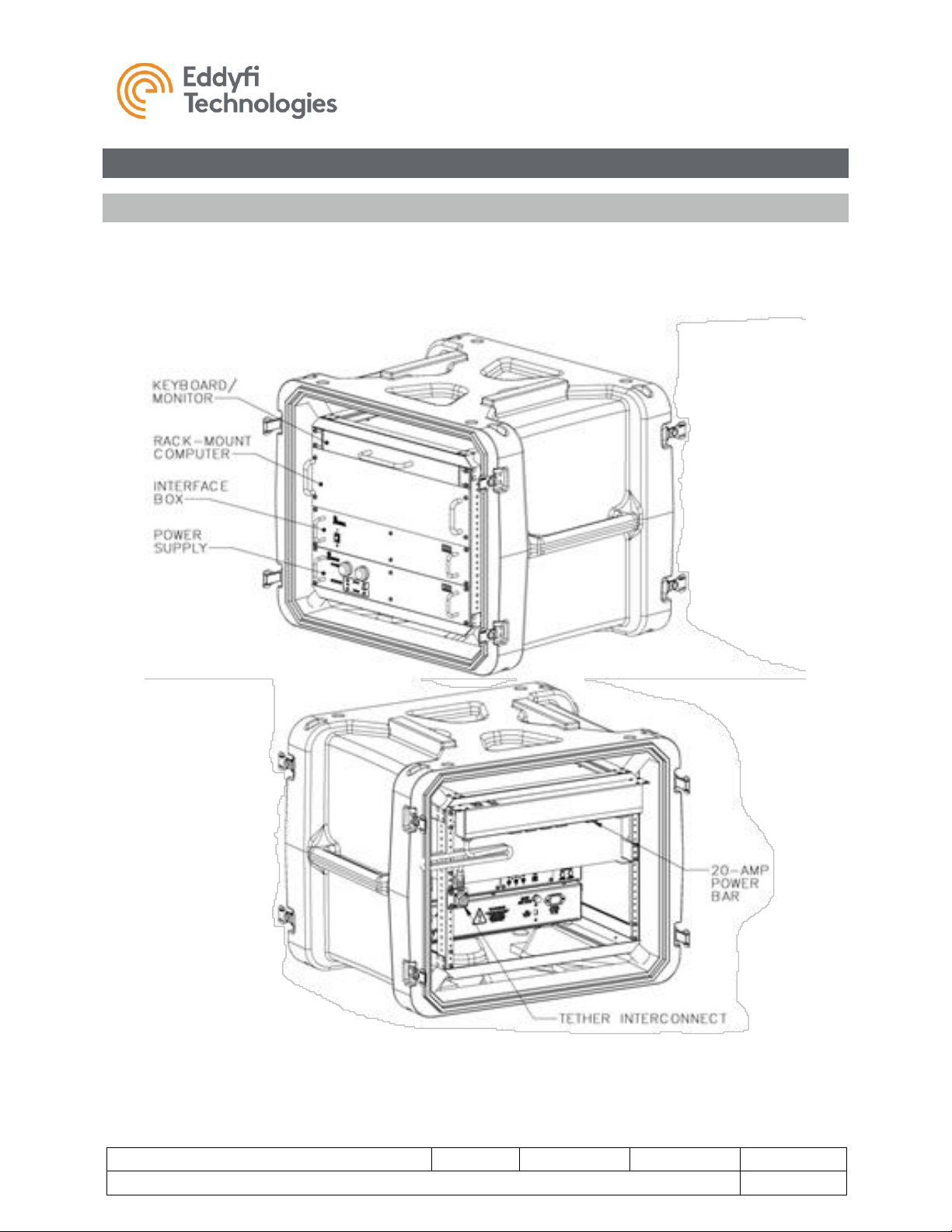
Pre-Configured Control Rack
The monitor, computer, interface box and power supply are typically installed and connected in a shockmount portable 19 in rack case. Systems pre-configured in a control rack will only need the tether, winch
and vehicle connections to be made before operations.
Versatrax 150™
Document: UMDW014058.docm
Revision: A03
Created by: KW
Date: 10 Oct 2019
3075415-A03
Source Location: C:\ePDM\ISLEng\products\dw-versatrax150mkii\manuals\UMDW014058.docm
Page 12 of 57
User Manual
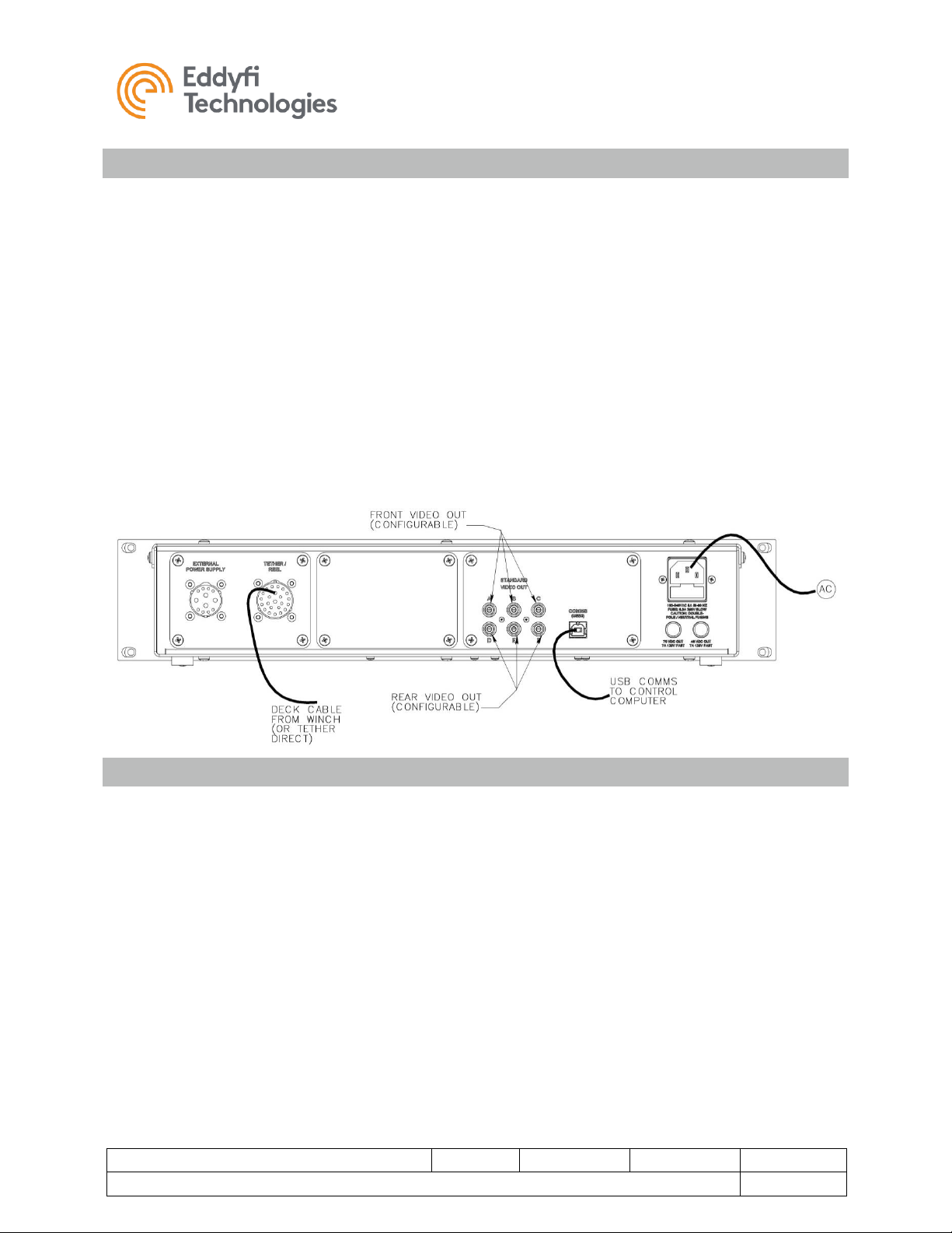
Control System Connections – SD Video
The ability to receive standard definition or high definition video depends on the interface box used with
the system. A standard definition interface box is depicted below which would be connected to the high
voltage power supply.
1. Connect the power supply to the interface box using the supplied interface cable. Ensure the
locking collars are screwed on all the way.
2. Connect the USB comms to the control computer.
3. Using equipment power cords connect the power supply and interface box to the 20-Amp power
bar supplied with the equipment rack. Note that the power bar will only accept equipment power
cords. The input cord on the power bar can be changed depending on the input voltage and
location.
4. Connect the tether (or deck cable from the winch or reel) to the interface box as illustrated below.
5. Connect the front monitor or video capture to channels A, B or C (three-way splitter) and the rear
monitor or video capture to channel D, E or F. These are the default output, but the connector
assignments are also software configurable.
Control System Connections – HD Video
A high definition interface box is depicted below which would be connected to the high voltage power
supply. For an HD system make the following connections:
1. Connect the power supply to the interface box using the supplied interface cable. Ensure the
locking collars are screwed on all the way.
2. Connect the USB2 comms to the control computer.
3. Using equipment power cords connect the power supply and interface box to the 20-Amp power
bar supplied with the equipment rack. Note that the power bar will only accept equipment power
cords. The input cord on the power bar can be changed depending on the input voltage and
location.
4. Connect the tether (or deck cable from the winch or reel) to the interface box as illustrated below.
5. Different options may be present for SD video, depending on interface box model. If the interface
box has an internal video capture card there will be two USB2 ports labelled Video A and Video
B. These will be the front and rear standard definition cameras on the vehicle. Analog SD video
is available as normal through the RCA connectors. Use A,B or C for front video (if this is an SD
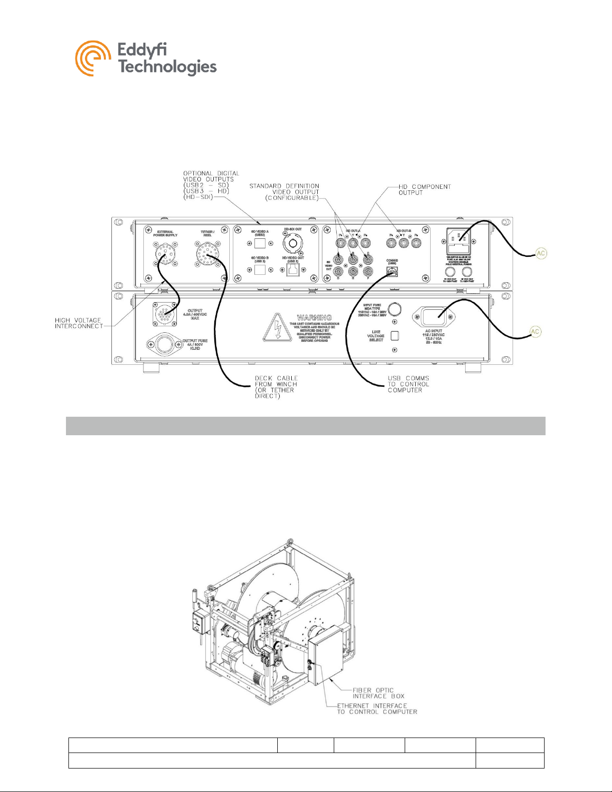
Versatrax 150™
Document: UMDW014058.docm
Revision: A03
Created by: KW
Date: 10 Oct 2019
3075415-A03
Source Location: C:\ePDM\ISLEng\products\dw-versatrax150mkii\manuals\UMDW014058.docm
Page 13 of 57
User Manual
video system) and D, E or F for rear video. There are spare front and rear video outputs which
can be connected to external monitors.
6. Options for HD video out include HD-SDI, USB3 (internal capture device) and component Pr-YPb. These connectors are for the front High Definition Camera. Spare connectors are active and
may be connected to external monitors, capture cards or recording devices.
Fiber Optic Tether
Systems equipped with a fiber optic tether employ a fiber bundle running down the middle of the tether to
transmit communications and video to and from the vehicle. The fiber bundle is terminated through a slip
ring into an interface box mounted to the side of the winch. All the necessary fiber receiver equipment is
in the interface box. From the interface box, video signals are routed through the deck cable as they
would through a copper tether, and control communications connect directly to the control computer
through an Ethernet cable.
See the winch manual for detailed operating instructions.
Versatrax 150™
Document: UMDW014058.docm
Revision: A03
Created by: KW
Date: 10 Oct 2019
3075415-A03
Source Location: C:\ePDM\ISLEng\products\dw-versatrax150mkii\manuals\UMDW014058.docm
Page 14 of 57
User Manual
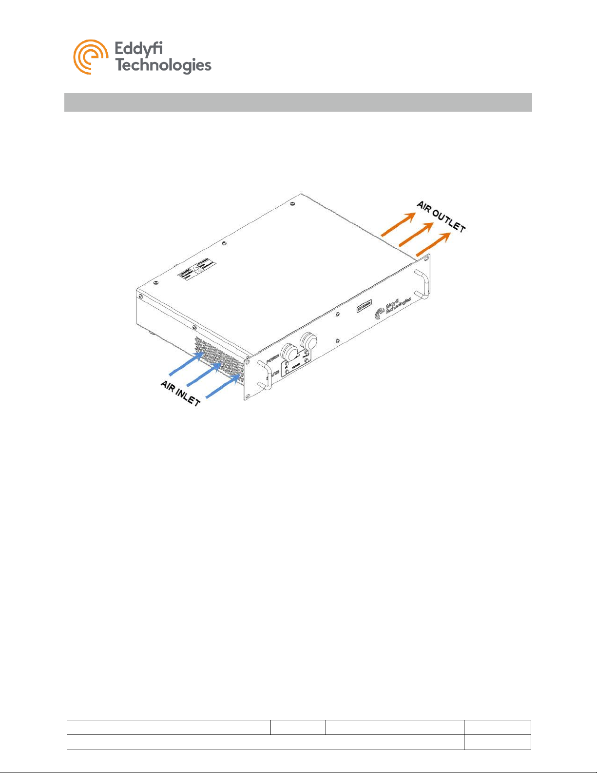
Client Configured Rack
If you are installing the power supply and interface box into your own 19 in rack installation, consideration
must be given to adequate air flow for cooling the power supply. In any installation, ensure that the air
inlet and outlet at the sides of the power supply are free of obstructions. The system could overheat if
airflow is restricted. The front or back of the 19 in rack must also be open for air flow.
Versatrax 150™
Document: UMDW014058.docm
Revision: A03
Created by: KW
Date: 10 Oct 2019
3075415-A03
Source Location: C:\ePDM\ISLEng\products\dw-versatrax150mkii\manuals\UMDW014058.docm
Page 15 of 57
User Manual
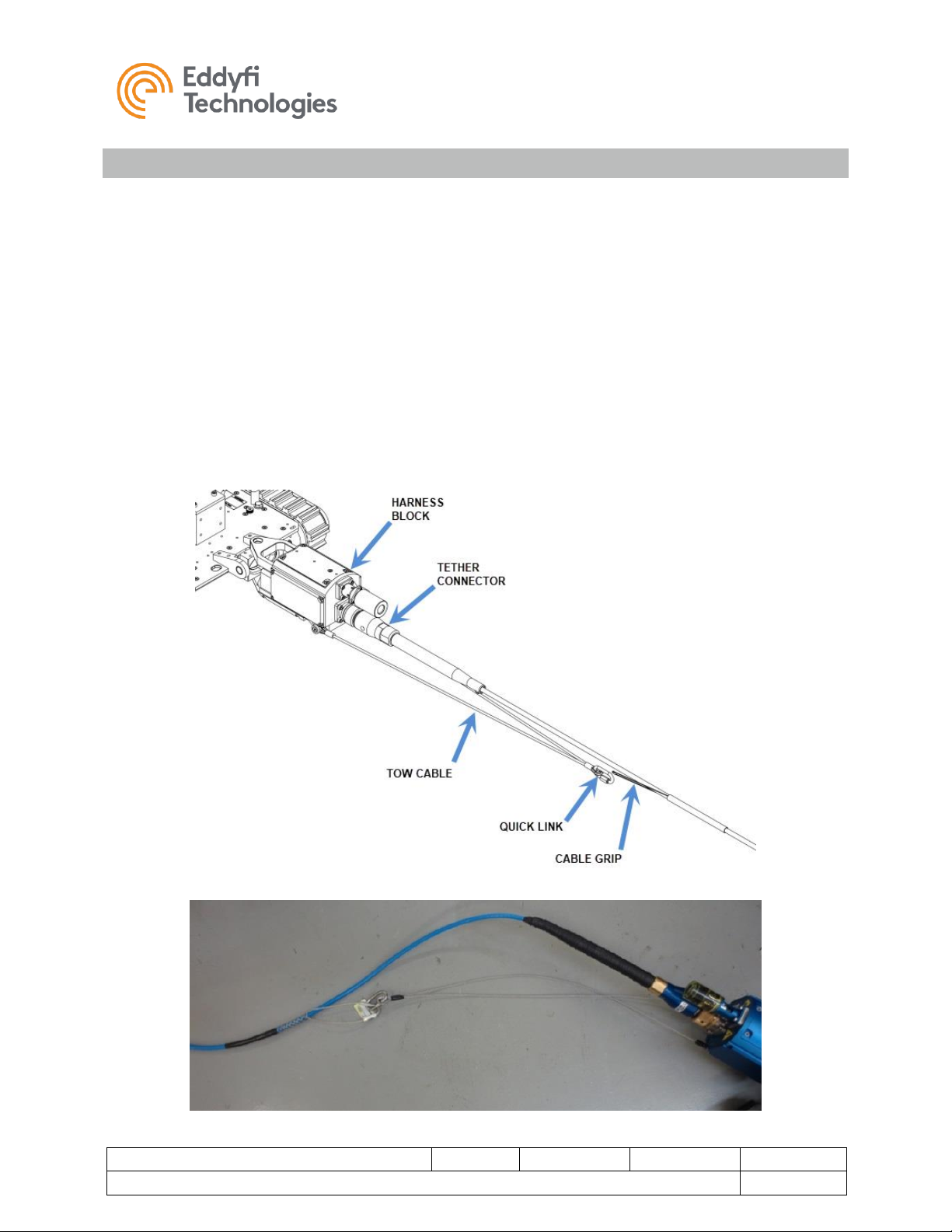
Vehicle and Tether
It is important that the tether be properly connected to the vehicle – otherwise damage to the system may
result.
1. Connect the vehicle end of tether to the back of the integrated harness block. Visually line up the
key in the connector before mating. Fully screw down and hand-tighten the locking collar.
2. Secure the tow cable to the cable grip on the tether using the quick-link. Adjust the cable grip
position to maintain a small amount of slack tether regardless the direction the tether is pulled, as
illustrated below.
3. Verify all device whips from the harness block to their respective components are securely
connected, and the whips are free from damage.
4. Ensure any unused connectors are capped with dummy plugs to insulate and protect their
electrical contacts.
5. Tether connection to the parallel and inline vehicles are identical.
Versatrax 150™
Document: UMDW014058.docm
Revision: A03
Created by: KW
Date: 10 Oct 2019
3075415-A03
Source Location: C:\ePDM\ISLEng\products\dw-versatrax150mkii\manuals\UMDW014058.docm
Page 16 of 57
User Manual
Winch Installation
If your system includes an AC powered winch refer to the winch manual for setup and installation
instructions.
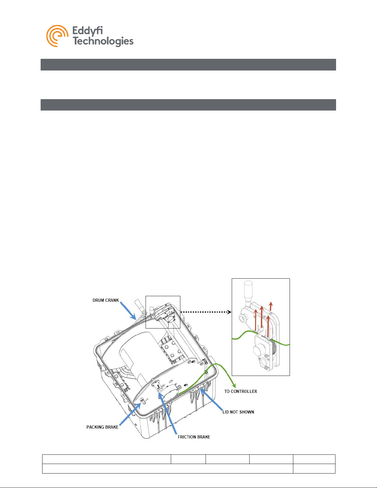
Portable Reel Setup
If your system includes a portable reel, follow these steps to operate:
1. Remove the shipping cap from the front of the case and insert the crank handle.
2. Connect the deck cable from the reel to the controller.
3. Disengage the packing brake (pull back and turn on the locking pin).
4. Make sure the friction brake is engaged; disengaging the friction brake can result in slack tether
potentially jamming the reel.
5. Unwind some tether and connect the tether to the vehicle.
6. Run the tether through the level wind as follows:
a. There is an access slot which must be opened by lifting up the two exposed screw heads
to raise the tether support shafts.
b. Pull up on both sides of the axle on the top wheel and slide the tether beneath it - failing
to lift up on the wheel can scuff and damage the tether.
c. Make sure that the two wheels that sandwich the tether top and bottom in the level wind
are tracking properly as the tether is paid out - this tells the controller how much tether
the reel has unwound and how far your vehicle has travelled.

Versatrax 150™
Document: UMDW014058.docm
Revision: A03
Created by: KW
Date: 10 Oct 2019
3075415-A03
Source Location: C:\ePDM\ISLEng\products\dw-versatrax150mkii\manuals\UMDW014058.docm
Page 17 of 57
User Manual
Tether Handling
The tether is one of the most important parts of the system. It feeds power and control signals to the
system and returns data to the controller. If the tether is damaged from improper use, poor handling or an
accident, the system may become inoperable. This could lead to significant downtime, loss of production,
and avoidable costly repairs. It is encouraged to stress the importance of the tether and its use to anyone
operating or maintaining the system. For maximum tether life and reliability, we recommend the following
tether handling tips.
• Do not step on the tether
• Do not drive over the tether
• Do not bend the tether beyond its minimum bend radius
• Do not kink the tether
• Do not snap load the tether
• Avoid loading the tether whenever possible
• Always use the cable grip strain relief if applicable to your system
• Regularly inspect the tether for damage
• Regularly clean the tether
Note:
Protecting the conductors inside the tether is critical to the life and operation of the tether.
Proper tether handling and care will result in extended tether life and system reliability.
Connector Handling
Connectors are an essential part of system reliability. They should be properly maintained and cared for
to ensure long life and reliability. It is recommended to follow these steps to help prevent damage and
increase the life of connectors.
• Always put the cap back on the tether bulkhead when the tether is disconnected
• Always inspect the end of the connector prior to engaging
• Never plug in a dirty or damaged connector
• Visually align key-ways or locating pins prior to engaging the connector
• Always fully engage or tighten the connector
• Secure locking collars finger tight
• Install dummy plugs on unused connectors
• Disconnect by pulling straight, not on an angle
• Do not pull on the cable to disengage the connector
IMPORTANT: Never “Hot Plug” any connector, this will result in internal damage to the
electronics. Power down the system prior to connecting the inspection system tether.
Note:
Never use WD-40 or similar solvent-based fluids on connectors or crawlers. These will cause
the rubber parts of the connector or crawler to soften and swell rendering them inoperable.

Versatrax 150™
Document: UMDW014058.docm
Revision: A03
Created by: KW
Date: 10 Oct 2019
3075415-A03
Source Location: C:\ePDM\ISLEng\products\dw-versatrax150mkii\manuals\UMDW014058.docm
Page 18 of 57
User Manual
SubConn Connector: Lubrication and Cleaning
• Periodically apply Molykote 111 silicone grease or equivalent before mating connectors
• For dry mate connections, a layer of grease corresponding to 1/10 the socket depth should
be applied to the female connector
• After greasing, fully mate the male and female connector and remove excess grease from the
connector joint
• General cleaning and removal of sand or mud on a connector should be performed using a
spray-based contact cleaner like isopropyl alcohol
Impulse Connector: Lubrication and Cleaning
• Lubricate mating surfaces regularly with 3M Silicone spray or equivalent, DO NOT GREASE
• Lubricate O-rings with Molykote 111 or equivalent
• Use dust caps to protect connectors wherever possible
• Clean connectors with soap and fresh water, rinse out with alcohol and allow connector to air
dry before using.
System Installation
The following describes a typical installation scenario recommended by Eddyfi Technologies.
Vehicle Layout
A typical set up for a pipe inspection system is based on a covered two ton or larger box truck. The truck
carries the power source (generator) and houses the power supply and control system in a dry, covered
environment. The computer / control console and recording equipment are placed in an office-like room
built into the truck. The rear wall of the truck should open completely. The winch, crane and other
equipment can be mounted at the back of the truck box near the door for easy deployment. The truck
should also contain the maintenance space with ample bench room for maintaining, configuring, and
washing down the vehicle and equipment.
The vehicle should be operated by a crew of at least two. Most importantly, a person should always be
available to tend to the tether. This person may also play a role in vehicle inspection and deployment. A
second person drives the vehicle, conducts the inspection and ensures a good recording.
The operations crew should be able to communicate quickly with each other to allow fast response in
case of an emergency like a tether hang up. It is recommended that a signal system be set up so that the
operators may work efficiently and safely as a team. It is always advantageous for both operators to be
aware of full system status.

Versatrax 150™
Document: UMDW014058.docm
Revision: A03
Created by: KW
Date: 10 Oct 2019
3075415-A03
Source Location: C:\ePDM\ISLEng\products\dw-versatrax150mkii\manuals\UMDW014058.docm
Page 19 of 57
User Manual
Vehicle Handling
Because the vehicle is heavy, some handling equipment is recommended with the system installation:
The first of these is a swinging overhead boom for vehicle deployment which must hold the payout
sheave axle at least 2.75 m (9 ft) above ground level. The capacity of the arm needs to be at least 450
kg (½-tonne) at full extension - enough for full vehicle weight plus full winch power. The payout sheave
diameter should be at least 250 mm (10 in) to help prevent tether fatigue.
An electric cable hoisting winch with at least 450 kg (½-tonne) load capacity is necessary to raise and
lower the vehicle. The cable on this hoist needs to be long enough for the deepest expected deployment.
Eddyfi Technologies recommends a dedicated work bench for vehicle configuration and maintenance.
Ideally this is at least 0.75 x 1.5 m (30 x 60 in) and is accessible from both sides. The lower portions of
the bench may be equipped with racks or drawers where tools, spare parts, and fasteners are kept.
Communication
Establish a good channel of communication between the operator and deployment personnel: whether
this is a system of signals, PA system or audio headsets. Good communication can avoid accidents,
damage to the equipment, and promotes efficiency and productivity. The person deploying the vehicle
and watching the tether must be able to quickly tell the operator to stop the vehicle when something goes
wrong. Because he is situated in the office-like van, the operator is often provided with a CCTV system
or view port so he can see directly what is happening with tether payout. It is best practice for the
operator never to turn on power or initiate movement without first communicating with the vehicle handler.
Personnel Requirement
A typical pipe inspection van operation usually requires two people for operations:
• Console Operator: This person is responsible for driving the vehicle, watching the pipe and
making comments about the location and pipe condition. It is also the operator’s responsibility to
assess whether a pipe is in the appropriate condition for safe passage of the vehicle or if there is
a risk of getting stuck. The operator may also assist in general site setup (cones, warning signs,
etc.), vehicle maintenance and configuration.
• Deployment / Tether Handler / Field Maintenance: This person has several tasks including:
o Configuring the vehicle for the current pipe
o Lowering the vehicle in and out of the manhole
o Watching the tether as the vehicle enters and exits the pipe
o Operating the winch and winding the tether during recovery

Versatrax 150™
Document: UMDW014058.docm
Revision: A03
Created by: KW
Date: 10 Oct 2019
3075415-A03
Source Location: C:\ePDM\ISLEng\products\dw-versatrax150mkii\manuals\UMDW014058.docm
Page 20 of 57
User Manual
Vehicle Configuration
Parallel Vehicle
Chassis Pipe Sizing
To fit inside specific pipe sizes, the chassis hinges must also be adjusted. To adjust the hinges:
1. Loosen the clamping nut; make sure the camera bed is far enough forward to provide access.
2. Adjust the hinges using the indicator plaque at the back of the chassis; the sizes indicated are
internal diameters (there is a line scribed on the main hinge that is used indicate pipe sizes).
WARNING: Pinch Hazard – Exercise extreme caution while adjusting the track
hinges not to catch your fingers in the linkages.
3. Once the hinges are set, re-tighten the clamping nut.
Note that there are two columns of numbers on the indicator plate. STD is for the standard chassis setup,
while XT is for when the track extension plates are installed.

Versatrax 150™
Document: UMDW014058.docm
Revision: A03
Created by: KW
Date: 10 Oct 2019
3075415-A03
Source Location: C:\ePDM\ISLEng\products\dw-versatrax150mkii\manuals\UMDW014058.docm
Page 21 of 57
User Manual
Powered Camera Raise
Note: When the powered camera raise is installed, the minimum pipe size is increased to 350 mm (14 in)
to allow room for the mechanism.
The camera raise needs to be zeroed before each use. Click the calibrate button on the ICON™
interface after system startup. The mechanism will lower itself to its lowest position, detected through a
magnetic switch. Note that the operator can control the motorized camera raise before calibrating after
system startup however the operator will not have any position feedback and it may be possible to
hyperextend the mechanism.
Note: The Powered Camera Raise will not position feedback until it is calibrated
using ICON (Inuktun Controller Software).
Warning: Keep hands clear of the camera raise when in operation as it presents
a potential pinching hazard.
Note: Always make sure there are no obstructions to the camera’s movement
before operating the camera raise.
When packing the Versatrax 150™ into the optional Pelican shipping case with the powered camera raise
installed, make sure to adjust the height of the camera to its shipping height before powering down the
system. For packing, the tracks should be set FLAT, and the height of the camera should be between
115 – 130 mm (4.5 – 5 in) measured from the floor to the support bar underneath the camera.

Versatrax 150™
Document: UMDW014058.docm
Revision: A03
Created by: KW
Date: 10 Oct 2019
3075415-A03
Source Location: C:\ePDM\ISLEng\products\dw-versatrax150mkii\manuals\UMDW014058.docm
Page 22 of 57
User Manual
Manual Camera Height Adjustment
If the Versatrax 150™ has a manually adjustable camera bed the height of the camera may be adjusted
as follows:
1. Remove the push button locking pin.
2. Adjust the height of the camera to the nearest locking hole.
3. Re-insert the locking pin.
Note that there are two columns of numbers on the indicator plate. STD is for the standard
chassis setup, while XT is for when the track extension plates are installed.
Minimum Bend Sizes
As the vehicle fits into smaller pipe sizes, the
minimum bend radius it can navigate becomes
restricted. The following table lists the minimum
bend radius for different sizes of pipe based on
a 90-degree bend, internal pipe diameters, and
the standard parallel chassis configuration.
Pipe ID
Bend Radius to
Centerline
305 mm (12 in)
Straight
355 mm (14 in)
5D – 1,780 mm (70 in)
405 mm (16 in)
3D – 1,220 mm (48 in)
455 mm (18 in)
1.5D – 685 mm (27 in)
510 mm (20 in)
1D – 510 mm (20 in)

Versatrax 150™
Document: UMDW014058.docm
Revision: A03
Created by: KW
Date: 10 Oct 2019
3075415-A03
Source Location: C:\ePDM\ISLEng\products\dw-versatrax150mkii\manuals\UMDW014058.docm
Page 23 of 57
User Manual
Spectrum 90™ Installation
The Versatrax 150™ can mount any of the Spectrum 90/120/120HD™ cameras. Installation is typical for
all three camera types as follows:
1. Adjust the camera bed to the position shown below. This will allow access to the camera
mounting screws. If a motorized camera raise mechanism is installed the system will need to be
powered up and raised into position. ALWAYS turn off the system before working near the raise
mechanism pinch points, which may cause injury to fingers and hands.
2. The purge valve indicates the top of the camera, as shown in Error! Reference source not
found.. Mount the camera with the valve on top.
3. Slide the camera into position from the front of the camera bed.

Versatrax 150™
Document: UMDW014058.docm
Revision: A03
Created by: KW
Date: 10 Oct 2019
3075415-A03
Source Location: C:\ePDM\ISLEng\products\dw-versatrax150mkii\manuals\UMDW014058.docm
Page 24 of 57
User Manual
4. Install the connector while the camera is part way in. Push the whip connector all the way onto
the camera. Make sure there is no gap between the rubber faces of the connectors. Screw the
locking collar onto the bulkhead connector; finger tight is good. Periodically apply a small amount
of silicone grease to the connector to keep it lubricated; however, avoid too much grease in the
female socket (vehicle side) because this can make the connector difficult to plug in.
5. Move the camera all the way to the rear tight to the camera mounting plate. Slide the connector
into the square opening and install the camera screws. Use M6 x 16 mm SHCS – note that older
cameras may use ¼-20 x 5/8 in SHCS.
M6x16mm SHCS

Versatrax 150™
Document: UMDW014058.docm
Revision: A03
Created by: KW
Date: 10 Oct 2019
3075415-A03
Source Location: C:\ePDM\ISLEng\products\dw-versatrax150mkii\manuals\UMDW014058.docm
Page 25 of 57
User Manual
Spectrum 120HD™ Installation
Because of the larger connector on the SP120HD™ camera, it is necessary to use spacers behind the
camera to make room for the connector as shown in Error! Reference source not found.. Thread the
spacers into the back of the camera and mount using 3x M6 x 16 mm SHCS as per the previous section.
Spectrum 120™ Bumper Bars
Bumper bars for the Spectrum 120 are installed directly onto the camera’s rotating head. Typically, the
bumper bars are installed at the factory during system assembly but can be retrofitted as follows:
1. Remove the two rear
screws (M6 x 14 mm
SHCS) from the
camera side-plates –
do one side plate at a
time and make sure
to hold the side-plate
secure so it does not
come loose from the
camera.
2. Install the bumper bar
assembly using 2x
M6 x 30 mm SHCS –
use blue Loctite 243.
Removal is the reverse of installation

Versatrax 150™
Document: UMDW014058.docm
Revision: A03
Created by: KW
Date: 10 Oct 2019
3075415-A03
Source Location: C:\ePDM\ISLEng\products\dw-versatrax150mkii\manuals\UMDW014058.docm
Page 26 of 57
User Manual
Light Installation
Light Mount When Using Standard Length Tracks
The 901 lights are installed onto the camera mount plate via mounting bracket as follows:
1. If the 901 mounting brackets are not installed, attach them to the back of the camera mount plate
using:
a. Older blue anodized chassis’ use ¼-20 x 5/8 in SHCS
b. Hard gray anodized chassis use M6 x 16 mm SHCS
2. Attach the lights to the front of the brackets using 2x M5 x 16 mm SHCS each.
3. Connect the whips to connector on the back of the lights, grease both the male and female
connectors with a dab of silicone grease.
4. Make sure the whips are routed properly through their P-clamps as shown (automatic camera
raise routing shown).
M6x16mm
SHCS
GRAY: M6x16mm SHCS
BLUE: ¼-20 x 5/8” SHCS
GRAY: M5x8mm
SHCS BLUE: #10-24

Versatrax 150™
Document: UMDW014058.docm
Revision: A03
Created by: KW
Date: 10 Oct 2019
3075415-A03
Source Location: C:\ePDM\ISLEng\products\dw-versatrax150mkii\manuals\UMDW014058.docm
Page 27 of 57
User Manual
Light Mount For Extended Tracks
When the extended tracks are installed, a different light bracket must be used to avoid interference
between the end of the tracks and the lights.
WARNING: Reduced Clearance. With the 901 lights installed with the extended
tracks, the vehicle will no longer fit into a 305 mm (12 in) ID pipe. Minimum pipe
size is increased to 355 mm (14 in)
To install the light mount:
1. Disconnect the lights and remove the regular light mounts from the frame.
2. Remove the camera
3. Remove the bumper bar holder (3/8-16 x 6 in SHCS).
4. Slide the light holder bracket over the bumper bars until it is 19 mm (0.75 in) away from the
back plate.
5. Use 2x M6 x 10 mm nylon tipped SSCREWs to secure holder to the bumper bars.
6. Reinstall the bumper bar holder and camera.
7. Install the lights onto the brackets using 2x M6 x 16 mm SHCS.

Versatrax 150™
Document: UMDW014058.docm
Revision: A03
Created by: KW
Date: 10 Oct 2019
3075415-A03
Source Location: C:\ePDM\ISLEng\products\dw-versatrax150mkii\manuals\UMDW014058.docm
Page 28 of 57
User Manual
FIGURE 1: 901 LIGHT INSTALLATION – EXTENDED TRACKS
Minitrac™ Installation
To install the Minitracs™ onto the parallel chassis, the vehicle must be configured as follows:
a. Lower the camera raise to the lowest position so the vehicle can be turned over.
b. Power the system down and disconnect the tether.
c. Remove any ballast weights.
d. Adjust the track hinges to the smallest pipe setting so that the inside screws are easily
accessible.
WARNING: High Voltage 400 VDC. Always make sure the system is powered
down and disconnected before performing any maintenance. 400VDC can cause
serious injury and death.
Once the vehicle is properly configured, install the Minitracs™ as shown below:
1. Lay the track onto the inner hinge as shown. The beveled ledge on the track should rest on a
step inside the hinge so that the bolt holes are at the correct height.
2. Bolt the inside link in place using 2x M6 x 16 mm SHCS and Loctite 243 (blue). Use the two rear
screw positions as shown.
STEP 1

Versatrax 150™
Document: UMDW014058.docm
Revision: A03
Created by: KW
Date: 10 Oct 2019
3075415-A03
Source Location: C:\ePDM\ISLEng\products\dw-versatrax150mkii\manuals\UMDW014058.docm
Page 29 of 57
User Manual
STEP 2
3. Tip the vehicle to access the outside hinge.
STEP 3

Versatrax 150™
Document: UMDW014058.docm
Revision: A03
Created by: KW
Date: 10 Oct 2019
3075415-A03
Source Location: C:\ePDM\ISLEng\products\dw-versatrax150mkii\manuals\UMDW014058.docm
Page 30 of 57
User Manual
STEP 4
4. Secure the outside hinge using 2x M6 x 16 mm SHCS and Loctite 243 (blue).
5. Secure the cabling as shown in the final illustration. The angled clamps are held on using M5 x 12
mm FHMS. The outside screw secures the cable with a P-Clip underneath.
STEP 5

Versatrax 150™
Document: UMDW014058.docm
Revision: A03
Created by: KW
Date: 10 Oct 2019
3075415-A03
Source Location: C:\ePDM\ISLEng\products\dw-versatrax150mkii\manuals\UMDW014058.docm
Page 31 of 57
User Manual
Track Height Extensions
Track extension plates simply bolt onto the outer hinges using M6 x 16mm socket cap screws. The tracks
then bolt onto the extension plates as they normally would on the chassis as explained in the previous
section. Extension plates increase the ground clearance of the vehicle from 41 – 69 mm (1.6 – 2.7 in),
depending on chassis configuration. With the extensions installed, the pipe sizes on the indicator plaque
are read from the XT column. Also note that the distance from the face of the P-Clips (see preceding
section) to the face of the Minitrac™ connectors must be increased from 310 mm (12 in) to 380 mm (15in)
by extracting cable length from inside the track hinges, and an additional 8 mm (0.31 in) P-Clip must be
installed on the inside extension plate in the hole provided.

Versatrax 150™
Document: UMDW014058.docm
Revision: A03
Created by: KW
Date: 10 Oct 2019
3075415-A03
Source Location: C:\ePDM\ISLEng\products\dw-versatrax150mkii\manuals\UMDW014058.docm
Page 32 of 57
User Manual
Spectrum™ Camera Extension
The optional camera raise extension is a bolt-on bracket which raises the camera by 356 mm (14 in).
1. Remove the camera, handle, bumper bars and mount, and lights and brackets from the vehicle
and install them on the extension bracket. The top of the extension bracket is made with the
same profile as the original camera mount.
2. Bolt the extension bracket onto the original camera mount. The fasteners used depend on the
chassis color. The height of the bracket can be adjusted to six different positions.
a. Blue anodized chassis – 2x ¼-20 x 5/8 in SHCS from the back and 1x 3/8-16 x 1¼ in
SHCS from the front.
b. Hard gray anodized chassis – 2x M6 x 16 mm SHCS from the back and 1x M10 x 20 mm
SHCS from the front.
3. Mount the camera and lights as usual on the extension bracket.
4. Install the supplied wiring harness extension to the camera and lights.

Versatrax 150™
Document: UMDW014058.docm
Revision: A03
Created by: KW
Date: 10 Oct 2019
3075415-A03
Source Location: C:\ePDM\ISLEng\products\dw-versatrax150mkii\manuals\UMDW014058.docm
Page 33 of 57
User Manual
Rear Camera Installation
The Versatrax 150™ system comes standard with a rear facing Inuktun Sapphire™ camera. A bulkhead
connector, mounting collar and dummy plug is included with the harness block at the back of the vehicle.
WARNING: High Voltage. The bulkhead connector is supplied 36-70 VDC. This
connector must be plugged with a protective cap whenever the Sapphire camera
is removed. Fatal shock or system damage may otherwise result. Never operate
the system with this connector open.
Note:
The Sapphire camera uses a higher voltage and different pin-out than the Inuktun Amber™
camera which is used on other Eddyfi Technologies equipment. You cannot use the Amber
with the Versatrax system. Attempts to install the Amber camera will damage the connector
and burn out the camera.
To install the Sapphire camera if not installed, do the following as shown below:
1. Remove the dummy plug from the rear bulk head connector.
2. Attach the mounting flange to the back of the Sapphire camera using 2x M3 x 16 mm FHMS.
3. Plug the camera into the bulkhead connector – make sure to align the mating pins and grease the
male connector.
4. Screw down the mounting plate using M3 x 8 mm SHCS.
Removal is the reverse of installation – make sure to cap bulkhead connector with a dummy plug.

Versatrax 150™
Document: UMDW014058.docm
Revision: A03
Created by: KW
Date: 10 Oct 2019
3075415-A03
Source Location: C:\ePDM\ISLEng\products\dw-versatrax150mkii\manuals\UMDW014058.docm
Page 34 of 57
User Manual
Advanced Accessories
Minitrac™ Length Extensions
Extensions may be added to the Minitracs™ to increase their length by 114 mm (4.5 in) to improve
vehicle stability and increase weight. The tracks mount to the chassis as normal, and configurations will
function as normal – with the exception that the 901 lights must be removed for use in 300 mm (12 in)
pipe. Refer to the section above on Spectrum 120™ Bumper Bars
Bumper bars for the Spectrum 120 are installed directly onto the camera’s rotating head. Typically, the
bumper bars are installed at the factory during system assembly but can be retrofitted as follows:
3. Remove the two rear screws (M6 x 14 mm SHCS) from the camera side-plates – do one side plate
at a time and make sure to hold the side-plate secure so it does not come loose from the camera.
4. Install the bumper bar assembly using 2x M6 x 30 mm SHCS – use blue Loctite 243.
Removal is the reverse of installation

Versatrax 150™
Document: UMDW014058.docm
Revision: A03
Created by: KW
Date: 10 Oct 2019
3075415-A03
Source Location: C:\ePDM\ISLEng\products\dw-versatrax150mkii\manuals\UMDW014058.docm
Page 35 of 57
User Manual
Light Installation for details.
Active Track Chassis Articulation
Active track gives the operator remote control over the chassis size configuration. Active track is
configured to install either on the left or right-hand side of the vehicle. Partial chassis disassembly is
required in order to install and is provided as a factory option – see the Active Track user manual for more
information.

Versatrax 150™
Document: UMDW014058.docm
Revision: A03
Created by: KW
Date: 10 Oct 2019
3075415-A03
Source Location: C:\ePDM\ISLEng\products\dw-versatrax150mkii\manuals\UMDW014058.docm
Page 36 of 57
User Manual
Sonde
A standard Ø19 mm (Ø0.75 in) battery powered sonde is able to mount on either side of the chassis as
shown below. The sonde depicted below is a Prototek FV-20 512 Hz. If the Active Track motor is
installed, the sonde can still mount behind the Active Track motor.
To mount the sonde onto the chassis do the following as shown below:
1. Clamp the sonde into the mounting bracket using a M5 x 20 mm SHCS
2. Fasten the sonde and bracket to the back of one of the top hinges using 2x M5 x 20 SHCS

Versatrax 150™
Document: UMDW014058.docm
Revision: A03
Created by: KW
Date: 10 Oct 2019
3075415-A03
Source Location: C:\ePDM\ISLEng\products\dw-versatrax150mkii\manuals\UMDW014058.docm
Page 37 of 57
User Manual
Fiber Optic Tether
If your system comes equipped with a fiber optic tether, do the following to mate the fiber termination
canister to the harness block as shown below:
1. Mate the electrical connectors between the fiber termination canister and harness block –
make sure to align the keyways on the top of the connectors.
2. Install the two connecting brackets with 2x M6 x 16 mm SHCS into each side of the
harness block and 2x M6 x 12 mm FHMS into each side of the termination canister.
3. Connect the rear camera and other auxiliary devices to the tether termination can. A
whip extension will be needed for the rear camera.

Versatrax 150™
Document: UMDW014058.docm
Revision: A03
Created by: KW
Date: 10 Oct 2019
3075415-A03
Source Location: C:\ePDM\ISLEng\products\dw-versatrax150mkii\manuals\UMDW014058.docm
Page 38 of 57
User Manual
Laser Scanner Mount
If your is equipped with an optional ULS-100 laser scanner module, it can be centered in the pipe by
adjusting the quick-release pin at the base of the linkage.
Mount the adjustable arm for the ULS-100 scanner to the underside of the main camera mounting block
using the M6 x 16 mm SHCS. Bolt the laser scanner with its mounting brace to the “L” shaped bracket at
the end of the adjustable arm using M5 x 20 mm SHCS. The scanner must connect to the harness block
through the power conversion can which drops the voltage from 48 VDC to 24 VDC. Run the cable
through the top of the linkage (not between the links) and secure using P-clips.
M6x16mm
SOCKET CAP SCREW

Versatrax 150™
Document: UMDW014058.docm
Revision: A03
Created by: KW
Date: 10 Oct 2019
3075415-A03
Source Location: C:\ePDM\ISLEng\products\dw-versatrax150mkii\manuals\UMDW014058.docm
Page 39 of 57
User Manual
Odometry Module
The odometry module is an optional factory installed module which provides the pitch, roll, heading,
ambient temperature and the distance travelled. It is secured to the bumper bar holder above the camera
using 4x M4 x 20 mm SHCS. Make sure the cable whips are installed and routed as shown.
The figure below shows how the orientation sensor is mapped relative to the vehicle.

Versatrax 150™
Document: UMDW014058.docm
Revision: A03
Created by: KW
Date: 10 Oct 2019
3075415-A03
Source Location: C:\ePDM\ISLEng\products\dw-versatrax150mkii\manuals\UMDW014058.docm
Page 40 of 57
User Manual
The axes are defined as follows:
• The Y axis is the length of the vehicle
• The X axis is the width of the vehicle
• The Z axis is the height of the vehicle
A clockwise rotation around the Y axis is defined as the positive direction (increases value). A clockwise
rotation around the X axis is defined as the positive direction (increases value). A clockwise rotation
around the Z axis is defined as the positive direction (increases value).
Note that the coordinate system and rotation directions can be redefined using ICON™
The odometer module has an optional T-type thermocouple. The usable temperature range of this
thermocouple is -200 – 350 °C (-330 – 660 °F). The thermocouple is accurate to +/- 1.0 °C (1.8 °F) or
1.5%.
The module connects to the wheel encoder located underneath the vehicle via the 6-position impulse
connector. The wheel encoder diameter is 80 mm (3.15 in) and outputs 256 pulses-per-revolution using
9-bit quadrature encoding.
If your system includes the Encoder, make sure the cable whip is installed and secured as shown below.

Versatrax 150™
Document: UMDW014058.docm
Revision: A03
Created by: KW
Date: 10 Oct 2019
3075415-A03
Source Location: C:\ePDM\ISLEng\products\dw-versatrax150mkii\manuals\UMDW014058.docm
Page 41 of 57
User Manual
Inline Vehicle
Minitrac™ Installation
WARNING: Pinch Hazard. Keep your fingers and hands out of the X-Hinge. Do
not hold or lift the vehicle by the X-Hinge. Severe pinching and hand injury may
result. Always use the handles next to the hinge for lifting.
All fasteners are M6 x 16 mm SHCS as illustrated above.
1. Lay the vehicle on the work bench with the tracks in the orientation shown. The far side plates
may remain attached to the handles and hinges as shown.
2. Plug the mating connectors into the tracks – make sure to align pins and grease the male
connectors
3. Attach the tracks to the far side plates.
4. Attach the free side plates to the tracks, handles and hinges.

Versatrax 150™
Document: UMDW014058.docm
Revision: A03
Created by: KW
Date: 10 Oct 2019
3075415-A03
Source Location: C:\ePDM\ISLEng\products\dw-versatrax150mkii\manuals\UMDW014058.docm
Page 42 of 57
User Manual
Spectrum 90™ Installation
Install the Spectrum™ camera on to the front of the vehicle using 3x M6 x 16 mm SHCS (older cameras
use ¼-20 x 5/8 in SHCS). Use Loctite 243 (blue) with all fasteners. Lubricate the connector with silicone
grease or silicone spray and fully engage the locking collar.
Guide Wheel Adjustment
For proper operation and stability, the chassis must be adjusted for the target pipe size.
Guide Wheel Adjustment: First, ensure the guide wheels are located correctly on the vehicle. As
illustrated below, the front guide wheels must be toed outward from the vehicle (by 2½°). An incorrect
installation (toed in) will result in vehicle instability. The rear guide wheels are straight.
Set the wheel height to suit the target pipe. The wheels should be just lightly touching the pipe. The
chart below outlines approximate wheel heights for standard pipe sizes. A guide wheel height gauge is
also provided with the system for generic pipe sizes.
Pipe ID
Wheel Height
150 mm (6 in)
28 mm (1.13 in)
200 mm (8 in)
16 mm (0.63 in)
255 mm (10 in)
13 mm (0.5 in)
305 mm (12 in)
11 mm (0.44 in)

Versatrax 150™
Document: UMDW014058.docm
Revision: A03
Created by: KW
Date: 10 Oct 2019
3075415-A03
Source Location: C:\ePDM\ISLEng\products\dw-versatrax150mkii\manuals\UMDW014058.docm
Page 43 of 57
User Manual

Versatrax 150™
Document: UMDW014058.docm
Revision: A03
Created by: KW
Date: 10 Oct 2019
3075415-A03
Source Location: C:\ePDM\ISLEng\products\dw-versatrax150mkii\manuals\UMDW014058.docm
Page 44 of 57
User Manual
Camera Height / Skid Adjustment
Rear Camera: The rear camera must be removed for 150 mm (6 in) pipe but may remain in place for 200
– 300 mm (8 – 12 in) pipe.
Camera Adjustment: There are four standard sizes of camera height adjustments; 150, 200, 250, and
300 mm (6, 8, 10 and 12 in). The 150mm (6 in) configuration will use a small skid under the camera.
Wheel placement for 200, 250 and 300 mm (8, 10, 12 in) pipe is illustrated below. Always use Loctite 243
with the shoulder screw. Wheel lubrication is not required.

Versatrax 150™
Document: UMDW014058.docm
Revision: A03
Created by: KW
Date: 10 Oct 2019
3075415-A03
Source Location: C:\ePDM\ISLEng\products\dw-versatrax150mkii\manuals\UMDW014058.docm
Page 45 of 57
User Manual
Rear Camera Installation
The Versatrax™ system comes ready to accept a rear facing Sapphire™ camera. The plug-in whip is
included with the harness block at the back of the vehicle. The Sapphire camera will come supplied with
a mounting bracket and installation hardware. Note that for inline configurations below 200 mm (8 in)
diameter may not have enough clearance for the rear camera.
WARNING: High Voltage. The mating whip is supplied 70 VDC. This whip must
be capped with a dummy plug whenever the Sapphire is removed. Shock or
system damage may otherwise result. Never operate the system with this
connector open.
Note:
The Sapphire camera uses a higher voltage and different pin-out than the Amber camera
which is used on other Eddyfi Technologies equipment. You cannot use the Amber with the
Versatrax system. Attempts to install the Amber camera will damage the connector and burn
out the camera.
Installation
1. Remove the cable clamp holding the camera whip.
2. Install the camera bracket as shown using 2x M4 x 8 mm PHMS.
3. Install the camera using 2x M3 x 16 mm PHMS. Note the camera orientation marked “TOP” seen
on the label inside the epoxy.
4. Plug the mating whip into the camera – make sure to align the pins and grease the male
connector.
5. Secure the locking collar after plugging in the camera.

Versatrax 150™
Document: UMDW014058.docm
Revision: A03
Created by: KW
Date: 10 Oct 2019
3075415-A03
Source Location: C:\ePDM\ISLEng\products\dw-versatrax150mkii\manuals\UMDW014058.docm
Page 46 of 57
User Manual
Operation
Pre-Operations Check
Before each deployment of the Versatrax™ system, ensure everything is completed on the following
checklist:
❑ Verify that the work area has been safely set up.
❑ Verify that the line voltage available at the worksite matches the equipment setup.
❑ Verify that power and deck cable connections are correct.
❑ Verify the vehicle for the following:
Check that the vehicle is in the correct configuration for the deployment.
Check the vehicle for mechanical damage to the chassis or cable harnesses which could affect its
operation.
Ensure that all fasteners are in place and secure. In particular, check the fasteners holding on
cameras, lights, tracks and tow cable.
Visually inspect the vehicle and Minitracs™ to ensure that the moving parts are free of debris and
functional. Make sure the track belt is free of debris and turns freely.
Check the tether and vehicle whips for damage.
Ensure camera viewports are clean.
Check the 901 light fins for fouling
Optional Components - Check that the screw on the automatic camera raise has been well
lubricated.
❑ Check the winch/reel for the following:
Check that nothing will block movement of the level wind shuttle.
Check that the tether has no loose, dangling coils. Dangling coils can propagate as the drum
rotates and have the potential to jump the drum. Take care of these before deploying the tether.
WINCH - Check that no objects, tools, etc., have fallen into the winch mechanism around the chain
and drum.
WINCH - Check that the drum lock is disengaged and latched open. (Models with a disk brake do
not have the drum lock pin.)
WINCH - Ensure that the drive clutch moves freely and is operational.
❑ Power up the system and check the following:
Check for sufficient SSD drive space for recording.
Check record directories are set.
Check video quality and camera control functions.
Test video recording.
Test main lights.
Test track control.
Verify automatic camera raise is zeroed.
Optional Components - verify operation of other optional components.

Versatrax 150™
Document: UMDW014058.docm
Revision: A03
Created by: KW
Date: 10 Oct 2019
3075415-A03
Source Location: C:\ePDM\ISLEng\products\dw-versatrax150mkii\manuals\UMDW014058.docm
Page 47 of 57
User Manual
Post-Operations Check
A Post-Ops inspection should be carried out after every deployment using the following checklist:
❑ Inspect the tether for damage as it is reeled in.
❑ Visually inspect vehicle for entrained debris or mechanical damage.
❑ Test each function to ensure proper operation.
❑ Clean the system by hosing it down with water at regular line pressure. Do not pressure wash. The
tracks may be cleaned off by hosing them down while running. If the system has been used in salt
water, thoroughly rinse the vehicle with fresh water right away.
CAUTION: Do not use a pressure washer to clean the camera. Very highpressure water can push past seals and flood the camera resulting in electrical
damage or personal injuries.
❑ Optional Components - Locate the automatic camera raise height at 80mm (3.1 inches) from its home
position for packing into the plastic shipping case.
❑ Take time to pack the system properly for transport away from the worksite.
❑ Store the system in a dry environment.
Note: Ensuring the Versatrax™ system is always stored in good working condition will minimize
deployment time for future inspections.
ICON™ & ICON™ RPT
Vehicle control and video recording are accomplished using ICON™ graphical interface controller
software. Video playback and reporting are conducted through ICON RPT. Manuals for these two
software packages are included separately. Controls for recording and snapshot functions are kept on-
screen with the camera controls.
• ICON Manual – (Control Interface and Recording)
• ICON RPT Manual - (Reporting, Playback and Video Export)
Power-Up Sequence
After all wiring connections have been made, the system may be powered up. The recommended
sequence for power-up is as follows:
1. Power up the control computer and allow time for it to fully boot.
2. Switch on the Interface Box.
3. Turn on the Vehicle Power Supply.
4. Start the ICON (Inuktun Control) control program.
ICON always begins with identification of attached system components (cameras, tracks, etc.). If vehicle
power is turned on after ICON is started, the system will not function until ICON is closed and restarted.

Versatrax 150™
Document: UMDW014058.docm
Revision: A03
Created by: KW
Date: 10 Oct 2019
3075415-A03
Source Location: C:\ePDM\ISLEng\products\dw-versatrax150mkii\manuals\UMDW014058.docm
Page 48 of 57
User Manual
Ground Fault Detection & Alarms
The front of the high voltage power supply includes power on and off buttons as well as status indicators.
The ON button and status indicators will light green during normal operation. The two red fault indicators
may light momentarily during startup and shut down; this is normal.
There are two status indicators:
1. Supply: This is the main power supply providing 400 VDC to the tether. A SUPPLY fault
warning will trigger if the AC power input drops below 85 VAC or if the power supply reaches
over-temperature levels. The power supply will be automatically shut down.
2. Tether: The power supply is also equipped with fault detection which monitors potential current
leakage from the high voltage power feed to the tether and vehicle. A TETHER fault warning may
indicate possible damage to the tether cable or water leakage inside the harness block or
Minitracs™. This fault will also be triggered if the output fuse has blown due to a short circuit.
Tether faults should not be triggered under normal operation and may be an indication of a major device
malfunction or a potential safety hazard. If a tether fault is announced, the power supply should be
disconnected and the reel, deck cable, tether, and vehicle harness whips should be inspected for
damage. If all cabling looks good, the Minitracs™ and integrated harness block should be examined.
If either of the fault indicators trip, the power supply will automatically disable power to the tether and
vehicle. The corresponding status indicator will light red and the ON button will flash to indicate external
power has been disabled. The power supply will not re-enable vehicle power until it has been reset by
pushing the OFF button.
WARNING: A ground fault alarm may be an indication of a safety risk. The system
should be turned off and carefully examined before powering back up.
Note:
The GFI fault detector monitors the high voltage DC power feed only and is not a
replacement for a proper GFCI protected AC power outlet.

Versatrax 150™
Document: UMDW014058.docm
Revision: A03
Created by: KW
Date: 10 Oct 2019
3075415-A03
Source Location: C:\ePDM\ISLEng\products\dw-versatrax150mkii\manuals\UMDW014058.docm
Page 49 of 57
User Manual
Dealing With Obstacles
The operator will invariably encounter a range of obstacles in a pipe. Each time the operator must decide
if the vehicle can safely pass or if there is risk of getting stuck. Common obstacles include but are not
limited to:
• Crushed pipe
• Sand
• Rocks, construction debris, random rubbish
• Roots
• Intersecting service pipes
• Animals and their nests
The Versatrax™ vehicle naturally straddles the debris at the very bottom of a pipe. If the debris is high
you may try installing the track extension brackets to give the chassis more clearance. Additionally, the
inside track weights may be removed to increase center clearance.
If the operator is unsure about pipe navigability, he or she should consult with the site supervisor before
moving forward.
Inspection Guidelines
The objective of an inspection is to obtain a recording of video and other data for review by the customer
or pipe owner. If a recording is lost, fails to record, or is of poor quality the inspection will likely have to be
re-done at the operator’s expense. Therefore, it is in the operator’s best interest to verify vehicle
operation, video quality and recorder function before beginning each inspection.
A set of video overlay comments and data are usually required depending on the contract or client. Initial
comments will usually include the location, pipe number and date. During the inspection the contractor
may require certain pipe features or faults to be pointed out along with the distance from the pipe entry.
Conduct a complete inspection of pipe features and faults. For any feature or situation of interest, stop
the vehicle and make a complete video survey using the continuous pan feature of the camera.
Ultimately, the inspection is conducted for the benefit of the client who is reviewing the footage later on.
Powered Winch Operation
Refer to the winch manual for winch installation and operating instructions.

Versatrax 150™
Document: UMDW014058.docm
Revision: A03
Created by: KW
Date: 10 Oct 2019
3075415-A03
Source Location: C:\ePDM\ISLEng\products\dw-versatrax150mkii\manuals\UMDW014058.docm
Page 50 of 57
User Manual
Vehicle Recovery
The Versatrax™ vehicle is designed for quick, efficient recovery by using the winch to tow it out of the
pipe. Just how quickly recovery can proceed will depend on the condition of the pipe and how far the
vehicle has traveled. Some factors may slow down recovery, such as distant travel into the pipe, bends
and corners.
If using an AC powered winch, do the following:
1. Begin retrieval by driving backwards a very short distance. This will disengage the track drive
clutches for towing with the winch.
2. If the vehicle has gone a long distance down the pipe it may require an excessive force on the
tether from the winch to tow the vehicle. To prevent this, begin by driving the vehicle in reverse
while simultaneously running the winch, hence taking the load of the vehicle off the tether.
3. Carefully watch the rear facing camera (if installed) whenever the vehicle is in reverse. Ensure
the tether is towed from behind the vehicle and there is adequate tension to avoid it going slack
behind the vehicle. Accidentally driving over the tether runs a high risk of breaking the tether or
jamming the vehicle.
4. If the tether tension does not seem excessive, and you know (from the inspection) that the pipe is
clear, you can tow the vehicle out with the winch. The winch will tow the vehicle between 60 and
100 feet per minute, depending on how full the drum is.
5. When the vehicle arrives at the deployment hole, stop towing and resume driving the vehicle. As
the vehicle comes under the opening the tow cable and back of the vehicle will begin to lift. At
this point stop and attach the lifting hoist.
Caution: Driving forward while the vehicle is being towed backwards by the winch
may damage the Minitracs™.
If you are using a portable reel the vehicle must be driven backwards while the tether is reeled in by
hand. The retrieval is similar to the powered winch. Follow these steps:
1. In order to ensure the tether is wound properly, have someone operate the level wind and spool
the tether as the vehicle is reversed.
2. Make sure the friction brake is engaged.
3. Make sure there is no slack in the tether on the reel.
4. As the tether is being wound, track the level wind back and forth so that the tether lies tightly
against itself in the reel.
5. Once the vehicle is recovered, pack up the reel in reverse order of setup.
6. Make sure the packing brake is engaged and the crank handle is removed and replaced with the
shipping cap.
7. If there is water pooled in the case from a wet tether, there is a plug at the bottom that may be
removed to allow the case to drain; always replace the plug after draining.

Versatrax 150™
Document: UMDW014058.docm
Revision: A03
Created by: KW
Date: 10 Oct 2019
3075415-A03
Source Location: C:\ePDM\ISLEng\products\dw-versatrax150mkii\manuals\UMDW014058.docm
Page 51 of 57
User Manual
Emergency Recovery
In the event the vehicle becomes disabled while on a mission in a pipe, provision has been made for
recovery of the vehicle by pulling it out with the tether. Recovering the vehicle by pulling is a serious
operation and can put great demand on the tether system. Listed below are three scenarios where the
vehicle may need to be recovered. Loading the tether beyond its maximum safe capacity should be
considered only as a last resort.
Note: Prevention is always the best policy. When traveling through a pipe or in any unknown area,
carefully watch your monitor.
The vehicle may become stuck if it is traveling through a damaged pipe section or improperly steered
around a corner. If the vehicle does become stuck:
1. Determine if it is the vehicle or the tether that is stuck. Look back at the tether with the camera if
possible. If the vehicle can back up but the tether will not reel in, the tether is caught on
something. Try to look for and fix the cause of the catch before putting any more strain on the
tether. The operator should use any dexterity available first to free the vehicle without resorting to
force.
2. If the vehicle cannot work itself free from a snag, try using light tether tension and tractor power
simultaneously.
3. If still stuck, try a stronger tether tension.
4. If the vehicle seems to be permanently stuck in the pipe, the supervisor must decide whether to
sacrifice the tether in order to pull harder, or to dig the vehicle out.
Troubleshooting
Camera Control Problems
• Not all the auxiliary lights are on.
o The ICON™ software allows the lights to be controlled independently. Ensure all lights
are enabled. Refer to the ICON interface manual.
o Inspect for failed LEDs.
Warning: High Intensity Light. Do not look directly into the lights. Use a welding filter (shade
#8) to observe the light elements.
• Camera pan or tilt does not function in one or both directions.
o Check that the camera is not jammed.
o If you can hear a motor running but see no movement, there is a gearing or clutch
problem inside the camera. Contact Eddyfi Technologies.
• Camera is moving very slowly.
o Check the pan & tilt speed in the camera control window. Refer to the ICON user
interface manual.

Versatrax 150™
Document: UMDW014058.docm
Revision: A03
Created by: KW
Date: 10 Oct 2019
3075415-A03
Source Location: C:\ePDM\ISLEng\products\dw-versatrax150mkii\manuals\UMDW014058.docm
Page 52 of 57
User Manual
Video Problems
• No video (black or blue background)
o Interface box is not turned on.
o Video cables are not hooked up between interface box and computer.
o Camera connector on vehicle is loose (turn power off first before plugging in camera).
o Check that the camera harness whip is plugged into the correct socket on the telemetry
can.
o Check monitor input settings.
o Vehicle power is not on.
o Check for problems with other video components between the computer and monitor.
o Try a different monitor. Whole days have been spent on field maintenance trips only to
discover a faulty monitor or faulty BNC / RCA video cable.
• Picture is very dark or very bright.
o Check the light levels of both the camera and main lights.
• Intermittent picture.
o Check and replace the video cables.
o Check the monitor is working properly.
o Check that the camera harness whip is fully plugged in.
o Check for intermittent breaks in the camera harness cable.
o Check the tether connectors at both controller and vehicle.
o Check for tether or slip ring damage by testing tether continuity.
• Picture is blurry, will not focus, or has poor color.
o This may be a dirty camera view port, or a narrow object lying in front of the view port.
o Object may be too close to the camera.
• No Rear Video
o Verify the video connection from the interface box to the computer.
o This may be a dirty camera view port, or a narrow object lying in front of the view port.
Vehicle Problems
• Vehicle won’t steer or vehicle runs backward.
o Tracks set to the wrong positions.
o Track reverse setting incorrect in control software.
o Node ID conflict between one or more devices on the vehicle.
• Tracks will not run.
o Check the track current feedback (See ICON™ manual).
▪ If current is at 100% and the vehicle doesn’t move, then the tracks may be
jammed. They could be wedged on an object or jammed with sand. Try
reversing the tracks to clear debris. If a jam will not clear you will have to recover
the vehicle by pulling it out with the tether.
▪ If no current is registered, then power or communication is not getting to the
tracks. Check all the cable connections.
o Try power cycling the system.
o Inspect the vehicle wiring for damage.
o Check all the system connectors.

Versatrax 150™
Document: UMDW014058.docm
Revision: A03
Created by: KW
Date: 10 Oct 2019
3075415-A03
Source Location: C:\ePDM\ISLEng\products\dw-versatrax150mkii\manuals\UMDW014058.docm
Page 53 of 57
User Manual
o Try restarting ICON™
o Listen for the track motors. If the motors run but the track doesn’t turn there is a problem
with the gearing or shaft pins.
o Try changing tracks. (ICON will require a restart.)
• Camera Raise will not move.
o For each time the system is turned on, the camera raise will not move until it is zeroed.
Click the CALIBRATE button on the ICON interface after system startup. The
mechanism will lower itself automatically to its lowest position until the limit switch is
detected.
o Check the connector to the camera raise motor.
o Try restarting ICON.
Winch Problems
• Tether distance does not read correctly.
o Check that the pressure wheel is pressing the tether against the payout sheave. If the
tether is being pulled up from the sheave instead of down, it may be disengaged from the
sheave.
o Check that the units are set properly in the graphical overlay.
o Recalibrate distance encoder.
o Ensure that the correct COM port is selected in the control software.
• Winch is very noisy.
o The short chain directly off the motor is too tight. This chain must run with some slack.
Refer to the winch manual.
• Winch does not run.
o Check that the winch has AC power.
o Check that the Emergency STOP button has not been pressed. (Twist to reset).
o After a power failure the run/stop switch must be reset.
o If there are no lights on the controller, check the fuse on the winch and in the motor
control box. Refer to the winch manual.
• Intermittent problems with vehicle or camera only when the winch is running.
o This may be caused by loose connectors.
o Slip ring may be damaged. Pin out the tether to check continuity with the winch drum
turning.

Versatrax 150™
Document: UMDW014058.docm
Revision: A03
Created by: KW
Date: 10 Oct 2019
3075415-A03
Source Location: C:\ePDM\ISLEng\products\dw-versatrax150mkii\manuals\UMDW014058.docm
Page 54 of 57
User Manual
Maintenance
Rinsing and Cleaning
After every mission check to see if the vehicle needs cleaning.
1. If the system has been used in salt water, thoroughly rinse the vehicle with fresh water prior to
being stored away. Accelerated corrosion will result if the inspection system is not rinsed
properly. Pay close attention to rinsing and cleaning the camera window, LED light dome and the
spaces between moving parts and track belts.
2. Use an open hose or tap at regular water line pressure for rinsing. Do not pressure wash the
equipment – water will be forced into the camera at these high pressures.
3. Avoid scratching the camera port. Use glass cleaner and a soft cloth to clean the port.
CAUTION: Do not use a pressure washer to clean the camera. Very highpressure water can push past seals and flood the components resulting in
electrical damage or personal injuries.
Periodically:
1. Use a damp cloth or spray cleaner for the power supply / controller box. The box must never be
sprayed down or immersed in water. Unplug the controller before cleaning.
2. For general cleaning of the cameras and tracks, use a mild detergent.
3. Clean the camera raise lead screw using a mild degreaser and re-grease with Molykote
G1502FM or similar grease.
Fuse Replacement
The controller and power supply contain panel mount fuses for both AC and DC voltages. These fuses
are for the safety of the operator(s) as well as to protect the equipment from damage. If a fuse blows, stop
and look for possible causes. Causes might include cable damage, water incursion or improper
connections. See the controller manual for fuse replacement.
Fuse values have been carefully selected for their application. Always replace the fuses with the same
type and rating.
Caution: Disconnect the power source before checking or replacing fuses.
Minitrac™ Maintenance
Refer to the Minitrac manual for Minitrac maintenance and servicing instructions.
Camera Maintenance
Refer to the Spectrum 90™ or Spectrum 120HD™ manual for camera maintenance and servicing
instructions.

Versatrax 150™
Document: UMDW014058.docm
Revision: A03
Created by: KW
Date: 10 Oct 2019
3075415-A03
Source Location: C:\ePDM\ISLEng\products\dw-versatrax150mkii\manuals\UMDW014058.docm
Page 55 of 57
User Manual
Tether Re-termination
Tether termination is a specialized service beyond the scope of this manual. Contact Eddyfi Eddyfi
Technologies if the tether is damaged or requires re-termination.
Parts and Repairs
Ordering Parts/Customer Service
Spare and/or replacement parts are available for your product and can be ordered directly from your local
office.
When ordering parts, always make sure to quote the sales order acknowledgement (SOA) number and/or
the serial number of the system component in question.
Eddyfi Robotics Inc. (Canadian Headquarters and Manufacturing Location)
2569 Kenworth Road, Suite C
Nanaimo, BC, V9T 3M4
CANADA
TF 1.877.468.5886
T +1.250.729.8080
info@eddyfi.com
www.eddyfitechnologies.com
Eddyfi Technologies – US (American Authorized Distributor and Service Centre)
812 W 13th Street
Deer Park, TX, 77536
USA
T +1.281.542.3292
info@eddyfi.com
www.eddyfitechnologies.com

Versatrax 150™
Document: UMDW014058.docm
Revision: A03
Created by: KW
Date: 10 Oct 2019
3075415-A03
Source Location: C:\ePDM\ISLEng\products\dw-versatrax150mkii\manuals\UMDW014058.docm
Page 56 of 57
User Manual
Warranty Repairs
Warranty conditions are specified in the Warranty section. Should any conditions of the manufacturer’s
warranty be breached, the warranty may be considered void. All returned items must be sent prepaid to
Eddyfi Technologies at the above address.
Factory Returns to Canada
Some sub-assemblies of your Eddyfi Technologies product are not field-serviceable and may need to
return to the factory for repair. Warranty claims must return to the factor for evaluation.
To return an item for evaluation or repair, first contact Eddyfi Technologies at our toll-free number or email address. Eddyfi Technologies will supply a Return Merchandise Authorization (RMA) number with
detailed shipping and shipping/customs instructions. Items shipped without an RMA number will be held
at Eddyfi Technologies until the correct paperwork is completed. If cross-border shipments are not
labelled as per the instructions, the items may be held by customs and issued additional fees.
All returned items must be sent prepaid unless other specific arrangements have been made.
When the product or system is being shipped anywhere by courier or shipping company, it must be
packaged in the original packaging it was received in. This measure greatly reduces the consequences
of rough handling and subsequent shipping damage.
Eddyfi Technologies cannot be held responsible for damages due to improper packaging. Shipping
damage may have significant impact on repair turnaround times.
Product/System Drawing Package Availability
Mechanical assembly and electrical wiring diagram drawings packages for your equipment are available
in PDF format upon request. Printed copies may also be purchased from Eddyfi Technologies. Contact
your local sales contact for more information.

Versatrax 150™
Document: UMDW014058.docm
Revision: A03
Created by: KW
Date: 10 Oct 2019
3075415-A03
Source Location: C:\ePDM\ISLEng\products\dw-versatrax150mkii\manuals\UMDW014058.docm
Page 57 of 57
User Manual
Limited Warranty Policy
Eddyfi Technologies will repair or replace, at its expense and at its option, any system or component,
subject to the limitations and / or exclusions specified herein, which in normal use has proven to be
defective in workmanship or material provided that, within one (1) year of the purchase date, the original
purchaser returns the product prepaid, accompanied by proof of purchase, from a sales agent authorized
by Eddyfi Technologies, and provides Eddyfi Technologies with reasonable opportunity to verify the
alleged defect by inspection.
Warranty Limitations and/or Exclusions:
1. This warranty does not apply to light bulbs.
2. Batteries, fuses, transistors, integrated circuit modules (IC’s), voltage regulating devices and electrical
plugs and / or connectors are warranted to be free from defects in material and workmanship for a
period of ninety (90) days from the date of shipment to the original purchaser.
3. Any article purchased from, but not manufactured by, Eddyfi Technologies is sold with only such
warranties as are made by the manufacturer therein. Eddyfi Technologies only warrants that it has
title thereto, free of all liens or encumbrances.
4. This warranty does not apply to units which are damaged by connection to improperly wired AC
receptacles.
5. Track belts, tethers, view ports and other components subject to wear through abrasion are
warranted to be free from defects in material and workmanship for a period of ninety (90) days from
the date of shipment to the original purchaser.
6. Any damage caused by failure to observe proper packing or to observe instructions for operation and
maintenance as contained in the Instruction Manual furnished with the equipment, by accident in
transit or elsewhere, will not be covered by the warranty.
7. Repairs are warranted for 90 days.
Eddyfi Technologies may require that certain components may be returned, prepaid, to a manufacturer’s
authorized station for inspection and repair or replacement.
Eddyfi Technologies will not be responsible for any asserted defect which has resulted from Acts of God,
normal wear, misuse, abuse, improper configuration, repair, or alteration made, or specifically authorized
by, anyone other than a representative of Eddyfi Technologies authorized to do so. The giving of, or
failure to give, any advice or recommendation by Eddyfi Technologies shall not constitute any warranty
by, or impose any liability on, Eddyfi Technologies.
The foregoing constitutes the sole and exclusive remedy of the purchaser and the exclusive liability of
Eddyfi Technologies and is in lieu of any and all other warranties, express, implied or statutory as to
merchantability, fitness for purpose sold, description, quality productiveness, or any other matter. Under
no circumstances shall Eddyfi Technologies be liable for special, incidental or consequential damages, or
for delay in performance of this warranty.
 Loading...