

.
2569 Kenworth Road, Suite C
Nanaimo, BC, V9T 3M4
CANADA
+1.250.729.8080
info@eddyfitechnologies.com
www.eddyfitechnologies.com
INUKTUN MINITRAC™

Minitrac™
Document: UMDC013503.docm
Revision: A11
Created by: KJB
Date: 26 Sep 2019
3072929-A09
Source Location: C:\ePDM\ISLEng\products\dc-minitracs8000\manuals\UMDC013503.docm
Page 2 of 24
User Manual
Table of Contents
About This Manual ........................................................................................................................................ 4
Description .................................................................................................................................................... 4
Product Description .................................................................................................................................. 4
Specifications ............................................................................................................................................ 5
Load & Speed Specifications: ................................................................................................................... 6
Basic Loading Specifications ................................................................................................................. 6
Influences on Loading ............................................................................................................................ 6
Additional Payload .............................................................................................................................. 7
Inclines ............................................................................................................................................... 7
Differential Steering ............................................................................................................................ 8
Curved Geometry ............................................................................................................................... 8
Elevated Temperature & Thermal Shutdown ..................................................................................... 9
Track Pin-Out .......................................................................................................................................... 10
Standard Tracks ................................................................................................................................... 10
High Voltage Tracks ............................................................................................................................. 10
Certification ............................................................................................................................................. 11
Safety .......................................................................................................................................................... 11
Setup & Operation ....................................................................................................................................... 13
Mounting Dimensions – Standard Length Belt ....................................................................................... 13
Mounting Dimensions – Extended Length Belt ....................................................................................... 14
Power Take-Off ....................................................................................................................................... 15
Maintenance ................................................................................................................................................ 16
Scheduled Maintenance and Servicing .................................................................................................. 16
Daily ..................................................................................................................................................... 16
Weekly ................................................................................................................................................. 16
Monthly ................................................................................................................................................ 16
General Cleaning .................................................................................................................................... 17
Belt Replacement & Tensioning (Spring Tension).................................................................................. 17

Minitrac™
Document: UMDC013503.docm
Revision: A11
Created by: KJB
Date: 26 Sep 2019
3072929-A09
Source Location: C:\ePDM\ISLEng\products\dc-minitracs8000\manuals\UMDC013503.docm
Page 3 of 24
User Manual
Belt Replacement & Tensioning (Manual Tensioning) ........................................................................... 18
Belt Removal / Replacement ............................................................................................................... 18
Block Tension and Alignment .............................................................................................................. 18
Gearbox Oil ............................................................................................................................................. 19
Checking the Oil ................................................................................................................................... 19
Draining / Filling the Oil ........................................................................................................................ 20
Overhaul ................................................................................................................................................. 20
Track Extension Block ................................................................................................................................. 20
Parts and Repairs ....................................................................................................................................... 22
Ordering Parts/Customer Service ........................................................................................................... 22
Warranty Repairs .................................................................................................................................... 23
Factory Returns to Canada ..................................................................................................................... 23
Product/System Drawing Package Availability ....................................................................................... 23
Limited Warranty Policy .............................................................................................................................. 24

Minitrac™
Document: UMDC013503.docm
Revision: A11
Created by: KJB
Date: 26 Sep 2019
3072929-A09
Source Location: C:\ePDM\ISLEng\products\dc-minitracs8000\manuals\UMDC013503.docm
Page 4 of 24
User Manual
About This Manual
This manual has been prepared to assist you in the operation and maintenance of your Eddyfi
Technologies Inuktun equipment. Correct and prudent operation rests with the operator who must
thoroughly understand the operation, maintenance, service and job requirements. The specifications and
information in this manual are current at the time of printing.
This product is continually being updated and improved. Therefore, this manual is meant to explain and
define the functionality of the product. Furthermore, schematics or pictorials and detailed functionality
may differ slightly from what is described in this manual.
Eddyfi Technologies reserves the right to change and/or amend these specifications at any time without
notice. Customers will be notified of any changes to their equipment.
Information in this manual does not necessarily replace specific regulations, codes, standards, or
requirements of others such as government regulations
This manual is copyright © 2019 by Inuktun Services Ltd. All rights reserved.
Description
Product Description
The Inuktun Minitrac™ 8000 crawler track is a small, self-contained tractor module complete with its own
electric motor and drive train. The track may be powered directly from a DC input or include its own
embedded drive electronics. Minitracs™ are designed for harsh environments such as confined spaces,
underwater, hot or cold temperatures, mud and sand, mild radiation, and chemical solutions. Applications
include storm and sewer pipe inspection, Oil & Gas inspection (Onshore/Offshore), potable water pipe
inspection, nuclear facility inspection / waste cleanup and OEM / custom-built systems. Standard length
Minitracs™ measure 420 x 100 x 84 mm (16.5 x 4.0 x 3.3 in), these can be fitted with an extension which
increase track length to 510 mm (20.1 in). Minitracs™ are made in three materials to meet application
needs: aluminum, brass, or stainless steel; and can have clutched or non-clutched drive wheels. In all
versions, the final drive power is delivered through a deep lug rubber track belt. Minitrac™ modules may
be operated in pairs to make a steerable platform or used in multiple pairs to make a steerable train.
Tracks are available in two voltage ranges: 36 – 70 VDC and 180 – 400 VDC.

Minitrac™
Document: UMDC013503.docm
Revision: A11
Created by: KJB
Date: 26 Sep 2019
3072929-A09
Source Location: C:\ePDM\ISLEng\products\dc-minitracs8000\manuals\UMDC013503.docm
Page 5 of 24
User Manual
Specifications
Operating Voltage
Standard
36 – 70 VDC
High Voltage
180 – 400 VDC
Operating Power
225W Peak
Operating Current
Standard
6.3 A Peak
High Voltage
1.3 A Peak
Maximum Speed
6.4 m/min (20.9 fpm)
Pull Rating
See Basic Load Specifications below
Payload
Up to 70 kg (150 lb)
Operating Temp
0 ° – 50 °C (32 ° – 122 °F)
90 °C (195 °F) Maximum Internal
Duty Cycle
In Water
100%
In Air
Dependent upon load and heatsinking
Communications
RS-485 Device Protocol
Feedback
Temperature, motor current, motor speed
Depth Rating
60 m (200 ft)
Weight
Standard Length
Aluminum
5.7 kg (12.5 lb)
Brass
12.2 kg (27 lb)
Stainless Steel
11.8 kg (26 lb)
Extended Length
Aluminum
7.2 kg (15.8 lb)
Brass
16 kg (35.3 lb)
Stainless Steel
15.4 kg (33.9 lb)
Lubrication
ISO 150 Food-grade Gear Oil
Minitrac™
Document: UMDC013503.docm
Revision: A11
Created by: KJB
Date: 26 Sep 2019
3072929-A09
Source Location: C:\ePDM\ISLEng\products\dc-minitracs8000\manuals\UMDC013503.docm
Page 6 of 24
User Manual
Load & Speed Specifications:
Basic Loading Specifications
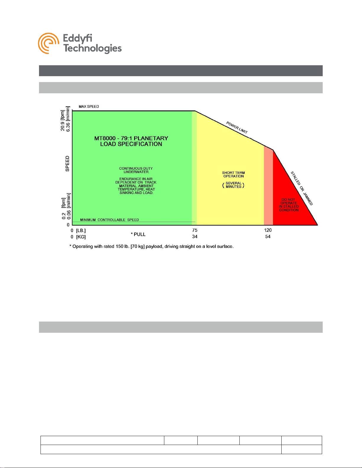
The above diagram details the speed and loading specifications of the standard 8000-Series Minitrac™.
There are three regions defining performance:
• Continuous Duty: Preferred continuous operating range.
• Short Term Operation: Operation permitted for several minutes.
• Stalled / Jammed Condition: Automatic limiting is engaged to protect the motor and gearing.
Do not operate the track in the stalled or jammed condition.
Influences on Loading
For a typical tracked vehicle there are multiple factors that can increase load and influence track
performance. These include the following and are detailed below:
• Additional Payload
• Inclines
• Effects of Differential Steering (skid steering with parallel tracks)
• Curved Geometry of a pipe
• Elevated Temperature / Poor Heat Sinking / Thermal Shut-Down
Minitrac™
Document: UMDC013503.docm
Revision: A11
Created by: KJB
Date: 26 Sep 2019
3072929-A09
Source Location: C:\ePDM\ISLEng\products\dc-minitracs8000\manuals\UMDC013503.docm
Page 7 of 24
User Manual
Additional Payload
Additional Payload may be added to the track, but the expected pull performance must be de-rated as
per the calculation below. Additional payload also affects differential steering, inclines and curved pipe
geometry (see below).
Pull Reduction = 0.25 x Extra Weight
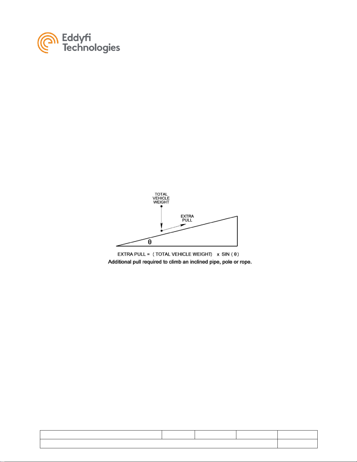
Inclines
Inclines cause the track to lift the vehicle weight against gravity and increase the track pulling load.
Calculate the incline load using the equation below. Magnetic downforce does not affect loading from
inclines — only forces from gravity. Note that the constant load from gravity becomes a significant factor
on vertical surfaces because the motor is working to resist the load even when the track is stopped.
Minitrac™
Document: UMDC013503.docm
Revision: A11
Created by: KJB
Date: 26 Sep 2019
3072929-A09
Source Location: C:\ePDM\ISLEng\products\dc-minitracs8000\manuals\UMDC013503.docm
Page 8 of 24
User Manual
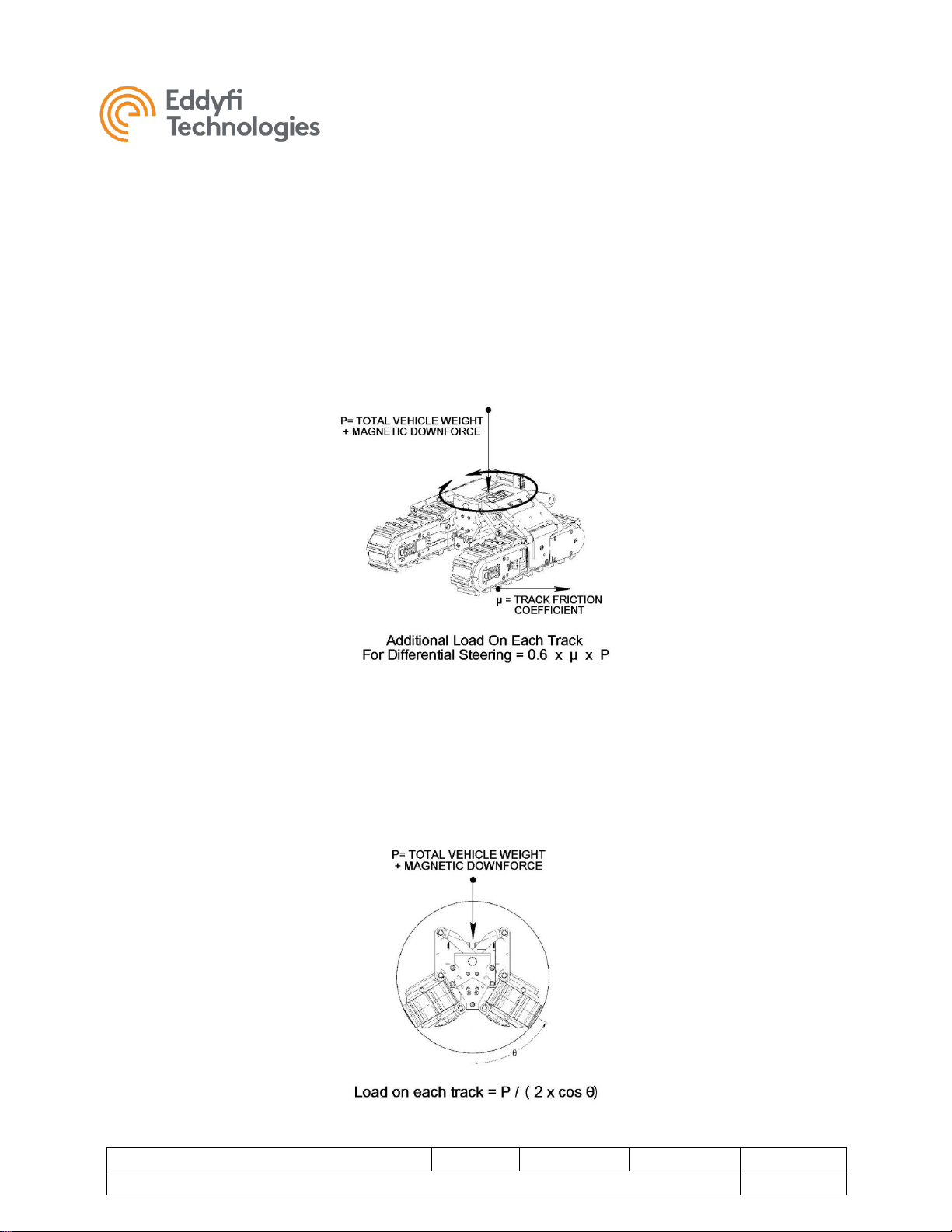
Differential Steering
Differential Steering means steering by varying the speed of two tracks such as with a tank or bulldozer.
During the steering process the tracks are dragged sideways in addition to forward / backward
movement. The sideways movement adds to the total track load and requires extra torque from the
motor. The greatest increase in loading occurs during a spot turn; the load being calculated as per the
figure below. A typical 41 kg (90 lb) VT150 MKII vehicle on a surface with friction coefficient µ = 0.5 will
experience an additional 12kg (27 lb) load per track to execute the spot turn. The same maneuver done
on fine dry concrete or low-pile carpet will result in over 23 kg (50 lb) of extra motor load! When steering
on a vertical surface include only the magnetic down-force for the differential steering load calculation.
Curved Geometry
Curved Geometry inside a pipe will increase the payload on a track depending on the angle of contact
with the pipe. For nearly flat tracks the increase is small. For a contact angle of 60°, the load is doubled.
The same calculation is used for a track contacting the outside of a pipe. Include both vehicle weight
and magnetic downforce for this calculation.
Minitrac™
Document: UMDC013503.docm
Revision: A11
Created by: KJB
Date: 26 Sep 2019
3072929-A09
Source Location: C:\ePDM\ISLEng\products\dc-minitracs8000\manuals\UMDC013503.docm
Page 9 of 24
User Manual
Elevated Temperature & Thermal Shutdown
‘Duty Cycle’ refers to the length of time a track can run before overheating. The duty cycle of the
Minitrac™ 8000 track depends on:
• Track Material Thermal Conductivity (Aluminum, Brass = Good; Stainless = Poor)
• Ambient Temperature
• Track Load & Speed
• Wet / Dry Operation
• Heat Sinking
A track typically converts about 25% of the electrical input into motive mechanical power with the
remainder being converted into waste heat transferred to the environment outside the track. When run
continually at maximum power in a warm environment - up to 50 °C (120 °F), the tracks can heat up to
the maximum temperature within ½-hour. However, this does not represent normal operation. Typical
usage will include much starting and stopping for visual/NDT inspections and moderate loading for most
of a pipe run for pulling tether – so reaching the thermal limit of the track is not expected to be a common
operational concern. When tracks are bolted to a chassis, it further acts as a heat sink to help cool the
tracks.
When a tracks internal temperature reaches 90 °C (195 °F) it will automatically shut down and wait until
its internal temperature drops below 75 °C (170 °F) before restarting. If the tracks are operating
underwater, such as in a flooded pipe, heat transfer is excellent, and the duty cycle may be considered
continuous.
Note: Stainless steel tracks will require special consideration for cooling, as they
reach thermal shutdown sooner due to the extremely poor thermal conductivity of
the stainless steel itself.

Minitrac™
Document: UMDC013503.docm
Revision: A11
Created by: KJB
Date: 26 Sep 2019
3072929-A09
Source Location: C:\ePDM\ISLEng\products\dc-minitracs8000\manuals\UMDC013503.docm
Page 10 of 24
User Manual
Track Pin-Out
Standard Tracks
The Standard Minitrac™ 8000 crawler track uses a 4-pin, low-profile connector (Subconn LPBH4M).
Contact Eddyfi Technologies for details of the RS-485 control protocol.
FIGURE 1: MINITRAC™ 8000 STANDARD PIN-OUT
High Voltage Tracks
The High Voltage Minitrac 8000 crawler track uses a 5-pin, low-profile connector (Subconn LPBH5M).
Contact Eddyfi Technologies for details of the RS-485 control protocol.
FIGURE 2: MINITRAC™ 8000 HIGH VOLTAGE PIN-OUT
Pin Number
Pin Function
1
48V +
2
48V GND
3
RS485A
4
RS485B
Pin Number
Pin Function
1
400V +
2
400V GND
3
RS485A
4
RS485B
5
NC

Minitrac™
Document: UMDC013503.docm
Revision: A11
Created by: KJB
Date: 26 Sep 2019
3072929-A09
Source Location: C:\ePDM\ISLEng\products\dc-minitracs8000\manuals\UMDC013503.docm
Page 11 of 24
User Manual
Certification
The Minitrac™ 8000 crawler track is built in accordance with the Machinery Directive 2006/42/EC, Low
Voltage Directive 2006/95/EC, Electromagnetic Compatibility Directive 2004/108/EC and Directive
2014/30/EU.
Safety
In order to be able to use this product properly and safely, every user must first read these operating
instructions and observe the safety instructions contained therein. Take care of these operating
instructions and keep them in a place where they can be accessed by everyone.
CAUTION: Failure to follow these safety instructions may result in injury or
equipment damage.
CAUTION: Disconnecting the track while the power is on can cause damage to
the track. Disconnect the power source before servicing the product.
CAUTION: High Temperature! Under rated operating conditions this track can
become very hot, up to 80 °C (175 °F).
WARNING: Spark Hazard - Under no circumstances should this equipment be
used in a potentially explosive atmosphere.
• The Minitrac 8000 is an industrial product. All personnel operating or maintaining this equipment
must be competently trained.
• There are no user serviceable parts inside. This product may be serviced only by qualified
technicians or trained personnel.
• Our equipment is used in many varied environments from hot/dry to confined spaces to deep
underwater. Such diverse environment risks must be addressed by the operators who are trained
to work in such surroundings. As such, the operator is responsible to determine safe site setup
and appropriate procedures for operation and maintenance of the equipment.

Minitrac™
Document: UMDC013503.docm
Revision: A11
Created by: KJB
Date: 26 Sep 2019
3072929-A09
Source Location: C:\ePDM\ISLEng\products\dc-minitracs8000\manuals\UMDC013503.docm
Page 12 of 24
User Manual
• Appropriate personal protective equipment (PPE) must be worn while operating and maintaining
the equipment.
• Do not use the product or any component exposed to pressures higher than the rated working
pressure.
In addition, observe the following precautions when cleaning or servicing the Minitrac™ 8000:
• Do not operate the track with a damaged connector or cable. Inspect connectors and cables
regularly for damage.
• Avoid creating a pinching hazard when designing a vehicle based on these tracks.
• Lay the track on its side if you are powering it up on the workbench.
• DC-Controlled tracks (without internal driver) must be protected by current limiting either by fuse
or electronically by the power supply. Current limiting and fuses are included standard with
Eddyfi system controllers.
Call the Eddyfi Technologies Service department for assistance or service if needed.

Minitrac™
Document: UMDC013503.docm
Revision: A11
Created by: KJB
Date: 26 Sep 2019
3072929-A09
Source Location: C:\ePDM\ISLEng\products\dc-minitracs8000\manuals\UMDC013503.docm
Page 13 of 24
User Manual
Setup & Operation
Mounting Dimensions – Standard Length Belt
Overall dimensions for mounting the Standard Length Minitrac™ 8000 crawler tracks are given in the
following Figures. The pattern of six M6 mounting holes is repeated on both sides. Maximum screw
penetration in the side plate is 12mm. Longer screws will bottom out or bind against the idler wheel.
Manual tensioning blocks may be required for Extended Length tracks in certain conditions.
FIGURE 3: STANDARD TRACK MOUNTING PATTERN (NOTE: THIRD ANGLE PROJECTION)

Minitrac™
Document: UMDC013503.docm
Revision: A11
Created by: KJB
Date: 26 Sep 2019
3072929-A09
Source Location: C:\ePDM\ISLEng\products\dc-minitracs8000\manuals\UMDC013503.docm
Page 14 of 24
User Manual
Mounting Dimensions – Extended Length Belt
Overall dimensions for mounting the Extended Length Minitrac™ 8000 crawler tracks are given in the
following Figures. The pattern of six M6 mounting holes is repeated on both sides. Maximum screw
penetration in the side plate is 12mm. Longer screws will bottom out or bind against the idler wheel.
Manual tensioning blocks may be required for Extended Length tracks in certain conditions.
FIGURE 4: EXTENDED TRACK MOUNTING PATTERN (NOTE: THIRD ANGLE PROJECTION)

Minitrac™
Document: UMDC013503.docm
Revision: A11
Created by: KJB
Date: 26 Sep 2019
3072929-A09
Source Location: C:\ePDM\ISLEng\products\dc-minitracs8000\manuals\UMDC013503.docm
Page 15 of 24
User Manual
Power Take-Off
The Minitrac™ 8000 crawler track features a power take-off shaft located just behind the drive wheel.
The shaft taps power from the main bevel gear, positioned in front of the final drive gears. Engage with
the shaft using a cup with a standard 4mm key. The speed of the shaft is roughly twice the drive wheel,
but at half the torque. Specifically, the gear ratio for the power take-off is exactly twice the planetary ratio
for your track. The power take-off may be used to drive other devices such as brushes, lead screws,
wheels, etc., effectively turning the track into a multipurpose servomotor. We recommend that you
remove the belt while using the power take-off.
FIGURE 5: MT8000 POWER TAKE-OFF
Minitrac™
Document: UMDC013503.docm
Revision: A11
Created by: KJB
Date: 26 Sep 2019
3072929-A09
Source Location: C:\ePDM\ISLEng\products\dc-minitracs8000\manuals\UMDC013503.docm
Page 16 of 24
User Manual
Maintenance
Minitracs™ 8000 have been designed to provide reliable performance and minimum downtime for
maintenance. The frequency of maintenance will be largely dictated by the type of use and the
environments the tracks are subjected to.Eddyfi recommends the following maintenance procedures.
Scheduled Maintenance and Servicing
The scheduled maintenance suggested below is in addition to normal equipment operation inspections.
Daily
Daily or before each use of the Minitracs™:
1. Visually inspect the Minitrac and track belt for damage; if the track belt is torn or stretched it may
need to be replaced. Check for correct belt tensioning.
2. Ensure that fasteners are in place and secure.
Note: Do not use the track if it looks damaged, or if the cabling looks
damaged.
Weekly
Verify by visual inspection that there are no traces of oil near or on the sides of the drive wheel
and the track belt. This would indicate that the oil seals may have been damaged by debris or
have become worn by abrasion.
Monthly
The monthly checklist provided below is suggested for all Minitrac™ types and should be performed more
often if the tracks are used extensively (more than 100 hours per month).
1. If muddy, thoroughly wash down the track body and wheels. Use only standard water line
pressure; do not use a pressure washer on the equipment. Remove and clean the track belt / skid
plate if dirt is packed underneath.
2. Remove buildup or dirt from drive wheel teeth.
3. Check the oil level and condition of oil.
4. For tracks equipped with a clutched drive wheel, test for the free-turning of the track belt. It should
be able to turn easily by hand in at least one or both directions. Any serious stiffness may be
caused by a jammed idler wheel, jammed drive wheel, or a build-up of sand under the belt or skid
plate. For tracks equipped with a direct-drive wheel, the belt should be able to be back-driven by
hand while the power is off to test for belt stiffness. Operating with a jammed belt may cause the
belt to tear.
Minitrac™
Document: UMDC013503.docm
Revision: A11
Created by: KJB
Date: 26 Sep 2019
3072929-A09
Source Location: C:\ePDM\ISLEng\products\dc-minitracs8000\manuals\UMDC013503.docm
Page 17 of 24
User Manual
General Cleaning
To maintain top performance and get maximum life out of the Minitrac™ and its seals, it is important to
prevent excessive dirt buildup under the track belt and around the wheels. Buildup may cause the track
to lose speed and pulling ability, ultimately reducing the life of the seals or stretching and ruining the track
belt. For best cleaning, the track belt should be removed.
For general cleaning of the Minitracs, wash with detergent and a stiff brush. The tracks may be sprayed
off using regular water line pressure.
Note: Do not pressure wash, or steam clean the tracks because they are not sealed against these
extreme pressures.
Belt Replacement & Tensioning (Spring Tension)
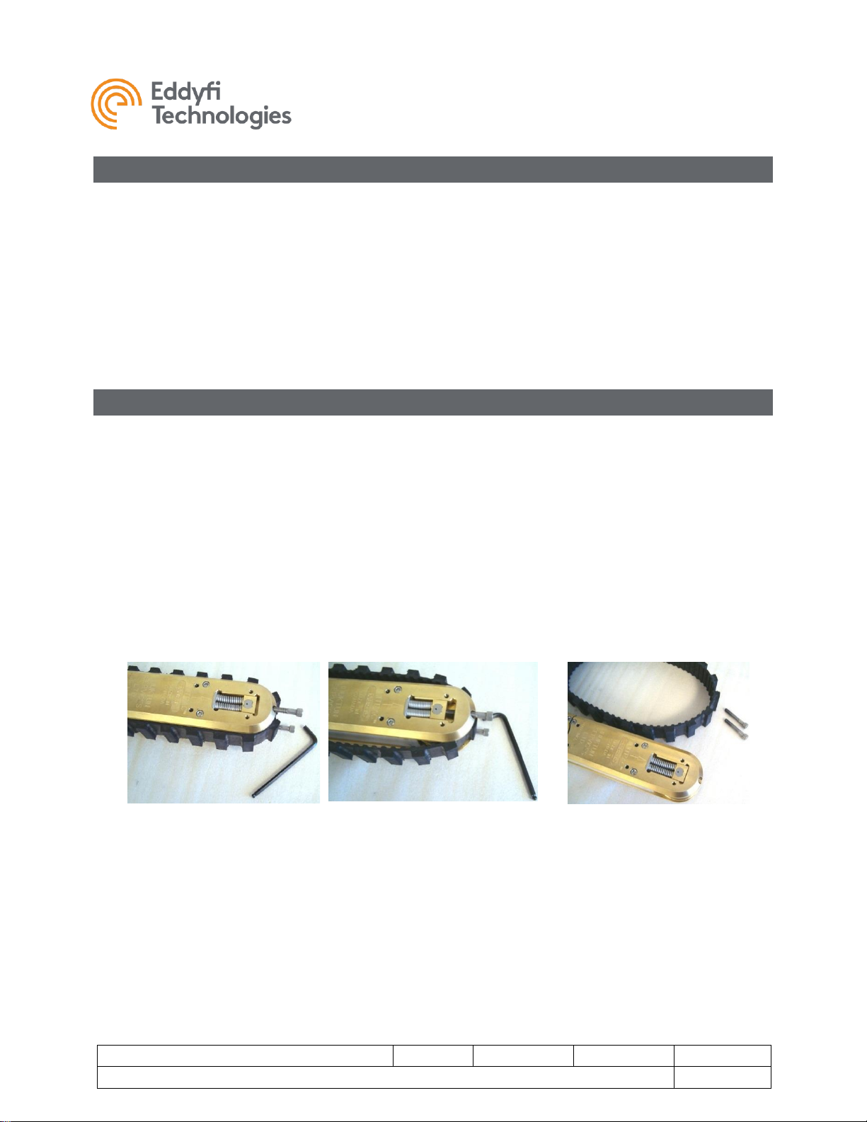
To remove the belt:
1. Install the spring compression screws (M8x50 socket cap screws) at the front of the track and
completely compress the tension springs as illustrated in the figures below. Note that the spring
compression screws should be lubricated with never-seize or light grease before use.
2. With the tension springs compressed, the belt is free to move by simply sliding it off the drive
(rear) wheel and over either side plate of the Minitrac, as below.
3. To install a new belt, place it on the idler wheel up front, then slide the belt over one of the side
plates and onto the drive wheel. When the tension screws are backed off again and removed,
the springs automatically tension the belt.
FIGURE 6: TRACK BELT REMOVAL STEP 1
FIGURE 7: TRACK BELT REMOVAL STEP 2
FIGURE 8: TRACK BELT REMOVAL STEP 3
Minitrac™
Document: UMDC013503.docm
Revision: A11
Created by: KJB
Date: 26 Sep 2019
3072929-A09
Source Location: C:\ePDM\ISLEng\products\dc-minitracs8000\manuals\UMDC013503.docm
Page 18 of 24
User Manual
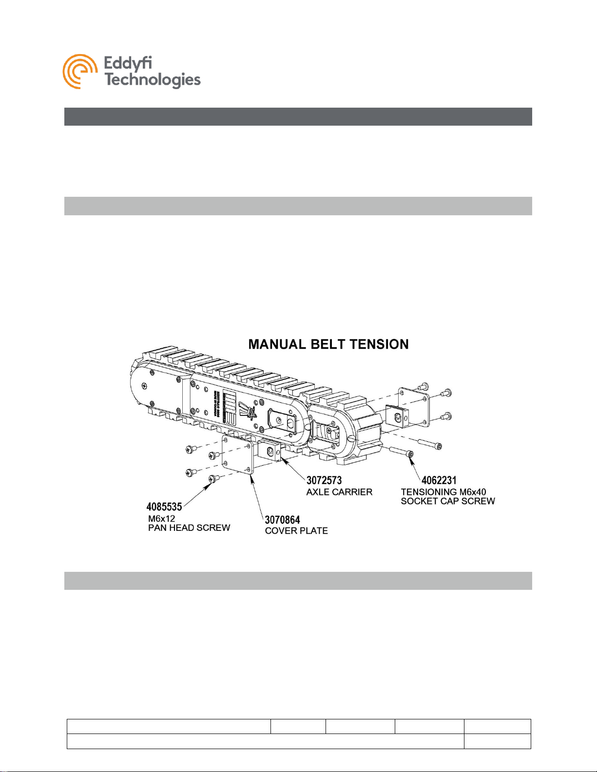
Belt Replacement & Tensioning (Manual Tensioning)
The manual tensioning block is an optional component for tensioning the track belt manually using a
tensioning screw instead of springs. This is sometimes required to prevent belt skipping when the track is
operated at full power in the reverse direction. Typically, the manual tensioning block is ordered with the
track from the factory but may also be ordered separately.
Belt Removal / Replacement
1. Referring to the figure below, remove the plastic cover plates and completely loosen the M6x40
idler wheel tensioning screws to release the belt tension.
2. The idler wheel will slide inward enabling the track belt to slip off the rear drive wheel.
3. Belts are installed again by placing the belt over the loose idler wheel, then slipping it onto the
rear drive wheel. Adjustment of the track belt tension and idler wheel alignment is described in
the next section.
FIGURE 9: IDLER COVER PLATE (SPRING REPLACEMENT BLOCK)
Block Tension and Alignment
Before tensioning the track belt, ensure the track is clean underneath the belt.
1. Belt tension and idler wheel alignment are adjusted using the M6x40mm tension screws located
in the end of the side plates near the idler wheel. The screws accept a 5mm Allen wrench.
Rotate the screws clockwise to tension and counterclockwise to slacken. Apply Loctite 243 to the
tensioning screws to prevent loosening and stainless-stainless thread galling in the idler shaft.

Minitrac™
Document: UMDC013503.docm
Revision: A11
Created by: KJB
Date: 26 Sep 2019
3072929-A09
Source Location: C:\ePDM\ISLEng\products\dc-minitracs8000\manuals\UMDC013503.docm
Page 19 of 24
User Manual
2. Belt tension should be adjusted evenly with each adjustment screw until there is no obvious slack
in the belt between the idler wheel and the drive wheel. When this is achieved, check the belt
tension (see next section).
IMPORTANT: The front idler wheel must now be properly aligned as described below. Misalignment of
the idler wheel will cause the track belt to rub against the side plates. This could degrade track
performance, potentially resulting in the track belt becoming completely jammed and stopping the unit.
3. Idler wheel alignment must be checked next, preferably by using a caliper. Measure the gap
between the forward portion of the idler wheel axle stub and the front end of the idler wheel
mounting slot on each side of the track body. The gaps on both sides must be equal to within 0.5
mm (0.020 in)
4. After the idler wheel has been aligned, re-check the track belt tension by pulling up on the middle
of the belt with your thumb. Correct track belt tension will allow a gap between 9 – 12 mm (0.38 –
0.50 in).
5. Next power up the Minitrac™ on its side to verify belt tracking, watching for an even gap between
the belt and the two side plates.
6. After the belt is aligned, replace the plastic side covers to prevent dirt and small bits of gravel
from falling between the idler wheel and belt.
Gearbox Oil
Checking the Oil
The oil level in the Minitrac should be checked at least once per month if the track is under heavy use.
The following outlines the procedure for checking the oil level.
1. The oil level is checked, drained, and filled by way of an oil port underneath the track belt either at
the top or bottom. To access the port, the track belt must be removed.
2. Once the belt and skid plate are removed clean off dirt from around the oil port.
3. Remove the oil plug. Ensure that the plug’s O-ring is clean and not damaged.
4. Inspect the oil. It is normal to see metallic wear particles from the gears. Under heavy operation
in gritty environments, the oil may become dirty due to grinding sand at the seal interface.
Change the oil if it is not clear.
5. The oil level must be just covering the transverse shaft visible through the hole when the track is
laying flat on a level surface.
Minitrac™
Document: UMDC013503.docm
Revision: A11
Created by: KJB
Date: 26 Sep 2019
3072929-A09
Source Location: C:\ePDM\ISLEng\products\dc-minitracs8000\manuals\UMDC013503.docm
Page 20 of 24
User Manual
Draining / Filling the Oil
1. Following the procedure above, locate and remove the oil plug.
2. Drain the oil into a clean pan, tray, or clear empty container by turning the track over and allowing
it to rest level for 20 minutes or so. This allows for the best possible visual inspection of frothing
oil, dirt, etc.
3. When replacing the oil, DO NOT OVERFILL THE TRACK. Oil should just cover the transverse
shaft visible through the oil fill-port. The oil will flow slowly inside the track requiring you to top up
the oil twice more after leaving the track to stand for ten minutes between fillings.
4. Re-install the oil plug, wear strip and track belt.
NOTE: Over filling the track may cause oil leaks under heavy loads because of the
volumetric thermal expansion of the oil.
NOTE: Minitracs™ 8000 crawler tracks are factory filled with ISO-150 weight food-
safe gear oil. Eddyfi recommends the continued use of food-safe gear oil when the
tracks are used in a clean environment. Otherwise, the tracks may be refilled with
SAE 30W motor oil. Tracks sent to Eddyfi for servicing will be refilled with ISO-150
food-safe gear oil.
Overhaul
For extended service and maximum reliability of your Minitracs, Eddyfi Technologies offers a factory
overhaul of the Minitrac. The factory overhaul constitutes an investment by the equipment owner in
preventative maintenance. As such, the overhaul should be considered discretionary. We recommend
that the Minitracs be thoroughly serviced once a year or after 500 hours of operation. This includes
complete disassembly, cleaning and inspection of the Minitrac components with focus on the drive train
and motor, and the replacement of O-rings and seals. In the overhaul, the track unit is completely
disassembled. All internal components including the belt, motor, driver, gears, bearings, and seals are
inspected and replaced where necessary.
WARNING: SHOCK HAZARD. High voltage components inside. This product
may be serviced only by qualified technicians or trained personnel.
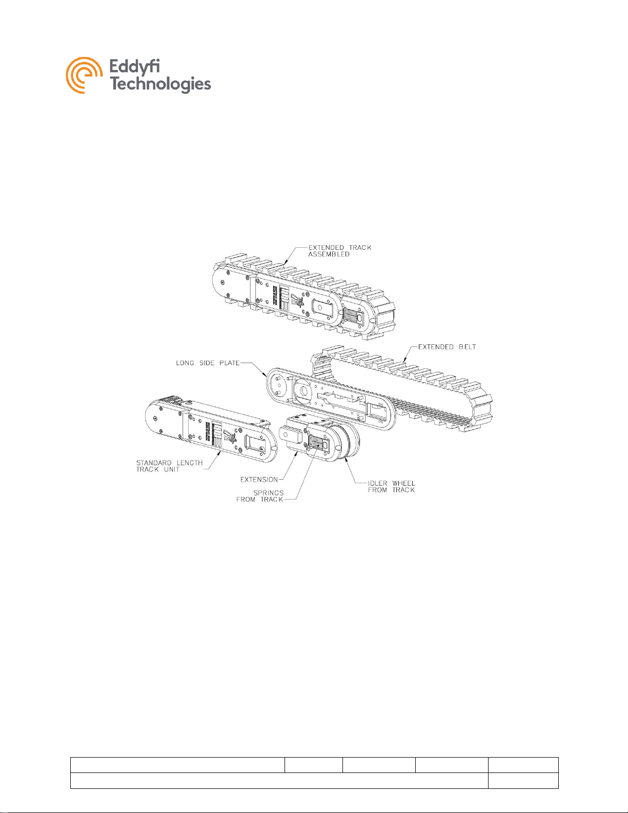
Track Extension Block
An extension block can be installed onto the Minitrac 8000 crawler track to enable use of an extended
track belt. This will extend the effective track length by 95 mm (3.8 in).
Minitrac™
Document: UMDC013503.docm
Revision: A11
Created by: KJB
Date: 26 Sep 2019
3072929-A09
Source Location: C:\ePDM\ISLEng\products\dc-minitracs8000\manuals\UMDC013503.docm
Page 21 of 24
User Manual
1. The extension block kit includes the block and extended track belt.
2. From your standard track, remove the belt, long side plate, idler wheel, and springs. The short
side plate opposite the connector must remain on the track.
3. Install the springs and idler wheel into the extension block. See Figure 10 below.
4. Install the assembled extension block onto the track. The block will clip into the slots where the
springs were installed before.
5. Install the extended track belt. See Belt Replacement & Tensioning.
FIGURE 10: TRACK EXTENSION BLOCK

Minitrac™
Document: UMDC013503.docm
Revision: A11
Created by: KJB
Date: 26 Sep 2019
3072929-A09
Source Location: C:\ePDM\ISLEng\products\dc-minitracs8000\manuals\UMDC013503.docm
Page 22 of 24
User Manual
Parts and Repairs
Ordering Parts/Customer Service
Spare and/or replacement parts are available for your product and can be ordered directly from your local
office.
When ordering parts always make sure to quote the sales order acknowledgement (SOA) number and/or
the serial number of the system component in question.
Inuktun Services Ltd. (Canadian Headquarters and Manufacturing Location)
2569 Kenworth Road, Suite C
Nanaimo, BC, V9T 3M4
CANADA
TF 1.877.468.5886
T +1.250.729.8080
info@eddyfi.com
www.eddyfitechnologies.com
Eddyfi Technologies – US (American Authorized Distributor and Service Centre)
812 W 13th Street
Deer Park, TX, 77536
USA
T +1.281.542.3292
info@eddyfi.com
www.eddyfitechnologies.com

Minitrac™
Document: UMDC013503.docm
Revision: A11
Created by: KJB
Date: 26 Sep 2019
3072929-A09
Source Location: C:\ePDM\ISLEng\products\dc-minitracs8000\manuals\UMDC013503.docm
Page 23 of 24
User Manual
Warranty Repairs
Warranty conditions are specified in the Warranty section. Should any conditions of the manufacturer’s
warranty be breached, the warranty may be considered void. All returned items must be sent prepaid to
Eddyfi Technologies at the above address.
Factory Returns to Canada
Some sub-assemblies of your Eddyfi Technologies product are not field-serviceable and may need to
return to the factory for repair. Warranty claims must return to the factory for evaluation.
To return an item for evaluation or repair, first contact Eddyfi Technologies at our toll-free number or email address. Eddyfi Technologies will supply a Return Merchandise Authorization (RMA) number with
detailed shipping and customs instructions. Items shipped without an RMA number will be held at Eddyfi
Technologies until the correct paperwork is completed. If cross-border shipments are not labelled as per
the instructions, the items may be held by customs and issued additional fees.
All returned items must be sent prepaid unless other specific arrangements have been made.
When the product or system is being shipped anywhere by courier or shipping company, it must be
packaged in the original packaging it was received in. This measure greatly reduces the consequences of
rough handling and subsequent shipping damage.
Eddyfi Technologies cannot be held responsible for damages due to improper packaging. Shipping
damage may have significant impact on repair turnaround times.
Product/System Drawing Package Availability
Mechanical assembly and electrical wiring diagram drawing packages for your equipment are available in
PDF format upon request. Printed copies may also be purchased from Eddyfi Technologies. Contact your
local sales contact for more information.

Minitrac™
Document: UMDC013503.docm
Revision: A11
Created by: KJB
Date: 26 Sep 2019
3072929-A09
Source Location: C:\ePDM\ISLEng\products\dc-minitracs8000\manuals\UMDC013503.docm
Page 24 of 24
User Manual
Limited Warranty Policy
Eddyfi Technologies will repair or replace, at its expense and at its option, any system or component,
subject to the limitations and / or exclusions specified herein, which in normal use has proven to be
defective in workmanship or material provided that, within one (1) year of the purchase date, the original
purchaser returns the product prepaid, accompanied by proof of purchase, from a sales agent authorized
by Eddyfi Technologies, and provides Eddyfi Technologies with reasonable opportunity to verify the
alleged defect by inspection.
Warranty Limitations and/or Exclusions:
1. This warranty does not apply to light bulbs.
2. Batteries, fuses, transistors, integrated circuit modules (IC’s), voltage regulating devices and electrical
plugs and / or connectors are warranted to be free from defects in material and workmanship for a
period of ninety (90) days from the date of shipment to the original purchaser.
3. Any article purchased from, but not manufactured by, Eddyfi Technologies is sold with only such
warranties as are made by the manufacturer therein. Eddyfi Technologies only warrants that it has
title thereto, free of all liens or encumbrances.
4. This warranty does not apply to units which are damaged by connection to improperly wired AC
receptacles.
5. Track belts, tethers, view ports and other components subject to wear through abrasion are
warranted to be free from defects in material and workmanship for a period of ninety (90) days from
the date of shipment to the original purchaser.
6. Any damage caused by failure to observe proper packing or to observe instructions for operation and
maintenance as contained in the Instruction Manual furnished with the equipment, by accident in
transit or elsewhere, will not be covered by the warranty.
7. Repairs are warranted for 90 days.
Eddyfi Technologies may require that certain components may be returned, prepaid, to a manufacturer’s
authorized station for inspection and repair or replacement.
Eddyfi Technologies will not be responsible for any asserted defect which has resulted from Acts of God,
normal wear, misuse, abuse, improper configuration, repair, or alteration made, or specifically authorized
by, anyone other than a representative of Eddyfi Technologies authorized to do so. The giving of, or
failure to give, any advice or recommendation by Eddyfi Technologies shall not constitute any warranty
by, or impose any liability on, Eddyfi Technologies.
The foregoing constitutes the sole and exclusive remedy of the purchaser and the exclusive liability of
Eddyfi Technologies and is in lieu of any and all other warranties, express, implied or statutory as to
merchantability, fitness for purpose sold, description, quality productiveness, or any other matter. Under
no circumstances shall Eddyfi Technologies be liable for special, incidental or consequential damages, or
for delay in performance of this warranty.
 Loading...